Relocation and Automatic Floor-planning of FPGA Partial Configuration Bit-Streams Jeff Carver, Neil Pittman, Alessandro Forin Microsoft Research August 2008 Technical Report MSR-TR-2008-111 Microsoft Research Microsoft Corporation One Microsoft Way Redmond, WA 98052
Transcript
Relocation and Automatic Floor-planning of FPGA Partial Configuration Bit-Streams
Jeff Carver, Neil Pittman, Alessandro Forin
Microsoft Research
August 2008
Technical Report
MSR-TR-2008-111
Microsoft Research
Microsoft Corporation
One Microsoft Way
Redmond, WA 98052
- 1 -
Relocation and Automatic Floor-planning of FPGA Partial Configuration Bit-Streams
ABSTRACT An extensible processor provides a standard data-path and one or more regions for use as application-specific reconfigurable logic. In this paper we address two problems that arise in the practical use of extensible processors. Using multiple extensible regions
can lead to avoidable time and space inefficiencies, and the physical placement of the interconnection points strongly affects the overall design timings.
Standard tool-flows from FPGA manufacturers require the creation of separate configuration images for each region. The space and time complexities that this entails are undesirable, especially in an embedded system setting where storage is at premium. In this paper we introduce a run-time algorithm that
allows the relocation of one configuration image to any number of compatible regions, in linear time. The application loader running on the data-path can perform the relocation along with the loading of the application code. We have implemented the algorithm on the eMIPS soft processor using two extensible regions, and on the MicroBlaze soft processor using four regions, in both cases targeting a Virtex-4 FPGA. There are two main advantages from image relocation. We save time at compilation because only one
region needs to be synthesized. We save space at execution time by storing only one configuration in FLASH memory.
The reconfigurable regions themselves are interfaced with the standard data-path using “bus macros”, connection points that are placed at fixed locations. The placement of the bus macros around a region has a noticeable impact on the timing of the design inside the region, and on the timings of the standard data-path outside the region. We have found that manual placement of the bus
macros is not only tedious, but leads to sub-optimal timings even when following best design practices. We present a tool that uses design-space exploration to obtain automatic, near-optimal placement of the bus macros for the relocatable regions. Results show the worst solution found had a total timing score of 581,146 ps while the best solution was only 22,964 ps and the average over the design space was 175,682 ps. The score for the manual placement was 97,714 ps.
1. INTRODUCTION Dynamic partial reconfiguration of FPGAs (or PR for short) has been available for quite some time, yet the tools to support it are still deficient in many ways. The flows are cumbersome to use and not at all integrated in the regular flow supported by the graphic user interfaces. This keeps many users away because the
technology is perceived as too difficult to use. But perhaps more importantly, there are still functional deficiencies that lead to sub-optimal solutions. In this paper we address two of the functional
shortcoming in the present tools. We have encountered these shortcomings in our own work with extensible processors, and therefore we have attacked them from a very practical perspective. Nonetheless, the issues are more widely relevant and affect all uses of the PR technology. The results are also more generally applicable.
The preferred model for PR use is with one static region and one PR region. The static region guarantees the basic functionality and
proper behavior during reconfiguration, especially with respect to the I/O signals. The single PR region is used to realize different temporal parts of the application, or alternate realization of certain (signal) processing, or to receive dynamic updates on deployed systems. Solutions that employ more than one PR region are described in the literature, but are not at all well supported by the tools. For example, the user is currently required to synthesize each design repeatedly, once for each PR region. Each
compilation requires hours of computer time, sometimes many hours if targeting the larger FPGA models. There are space inefficiencies as well. Each of those long compilations produces a separate configuration file (bit-stream) for use with the given PR region and nowhere else. These files are large even for the smallest FPGA models and easily grow in the hundreds of kilobytes. All of the files must be present at run-time. These time and space inefficiencies lead to the desire to, somehow, use a
single bit-stream file that can be relocated to any one of a many PR regions. Relocations should be doable at run-time, without excessive overhead. The file should be compiled only once, for one PR region only, and should be no bigger than a current file. In this paper, we describe the algorithm we have realized for performing the dynamic relocation of bit-streams. We demonstrate relocatable configuration files on two separate examples. One demonstration is with two PR regions using the
eMIPS extensible processor presented in [8]. The other demonstration is with four PR regions, using the MicroBlaze soft-core for image transformations on different parts of a digital image, and displayed on a VGA monitor. The two examples use radically different memory subsystems, which leads to different performance characteristics of the relocation process. The code for relocation, however, is the same in both instances. We also found that the composition of the bit-streams, as well as the location differences in PR regions are factors that affect the
relocation times just as much as the sheer size of the streams themselves.
A second shortcoming is in the interface between the static and the PR regions. Clearly, if independently developed designs for these regions are to interoperate correctly, at the very least they must agree on the routing and directions of the signals that
- 2 -
interconnect them. These are commonly referred to as the “bus macros”, using the terminology used for but one of the many ways in which the problem has been solved. While the problem is indeed solved, the current tools require the user to specify manually both the size and location of the PR regions, and the
location of the interconnecting points (the “bus macros”) along the perimeter of the PR regions. It turns out that the placement of the bus macros around a region has a noticeable impact on the timing of the design inside the region, as well as on the timings of the design outside the region. We have found that manual placement of the bus macros is not only tedious, but leads to sub-optimal timings even when following best design practices. Our solution is to create a tool that can automatically identify what is
the placement of the interconnection points that leads to the best timings. Our tool uses design-space exploration via simulated annealing to obtain automatic, near-optimal placement of the bus macros for the relocatable regions. To the best of our knowledge, this is the first tool to address the problem of identifying the best placement of the bus macros, manually or otherwise. To underscore the practical relevance of the problem, our results show that the ratio between the best and worst placement can be a
factor of 27 on a real design. The average solution is a factor of 8 slower than the best. The score for the manual placement that follows the best-practices advice from the manufacturer is a factor of 4.5 worse than best.
The rest of the paper is organized as follows. Section 2 presents background material and related work. Section 3 describes the bit-stream relocation algorithm, the tool flow, and their implementation. Section 4 presents the automated tool for floor-
planning of the bus macros. Section 5 presents our measurements and results. Section 6 describes the limitations of our current tool implementations. Section 7 presents our conclusions and Section 8 some ideas for future work.
2. BACKGROUND AND RELATED WORK This section introduces the background concepts needed for the
rest of the paper. They include FPGA partial reconfiguration, dynamic bit-stream relocation, the eMIPS processor, the MicroBlaze processor, the Virtex-4 configuration frame layout, and the floor-planning of partial reconfiguration regions.
2.1 Partial Reconfiguration and Relocation The ability to change portions of the FPGA configuration at run-time is called dynamic partial reconfiguration. This entails modifying portions of the logic planes without affecting the remaining parts of the circuit, which continues to function unperturbed. Special support is needed in the FPGA chip for this process to execute flawlessly, without “glitches”. Manufacturers that support this feature include Xilinx and Altera. Currently the tool provided by Xilinx for doing dynamic partial reconfiguration
is part of the Early Access Partial Reconfiguration, or EAPR, a flow that is found at [1]. The flow requires first implementing the part of the logic, called the static logic, which will not change during run-time. The logic that will change during run-time is implemented in a Partial Reconfiguration (PR) region. Each of the configurations of a PR region is implemented after the static part is implemented. Each implementation produces a configuration file, called a bit-stream. The final step is to generate the bit-stream
for the initial configuration of the entire chip, and for each alternate configuration that was implemented for each PR region. The communication between the PR region and the static logic happens via bus macros, fixed interconnection points at the
perimeter of the PR region. The bus macros must be instantiated in the HDL code and manually placed. The PR regions are reconfigured either off-chip by an external agent, or on-chip by the design itself, probably a processor. Off-chip interfaces use either JTAG, or some other specialized interface. To perform on-
chip reconfiguration on Xilinx devices, a designer instantiates a special macro for the Internal Configuration Access Port (ICAP), then sends the configuration data to it. For the Virtex-4 the ICAP can be implemented with either an 8-bit or 32-bit wide interface.
The bit-stream for configuring one PR region is tightly bound to the physical location of that region and cannot be used directly to reconfigure any other portion of the chip. In many cases though, it is possible to modify an existing bit-stream and adapt it to a
different physical location. This process is termed bit-stream relocation and can be performed statically by tools operating on the designer’s workstation, or dynamically by the agent that loads the bit-stream on chip. The key element is that a portion of the chip is reconfigured at run-time, without interfering with the operation of the rest of the chip. There are various works describing static or dynamic relocation of configurations for a PR region to a different PR region. The motivation is to reduce the
number of partial bit-streams required if two or more PR regions would use the same implementation. For example, if we had four target PR regions for the bit-stream we could save the storage of three bit-streams copies on, say, a FLASH chip and reduce the compilation time by a factor of four. The savings are noticeable because bit-streams tend to be large and the compilation times are often measured in hours per design. The trade-off is the size of the software/hardware and some placement restrictions on the PR
regions to enable relocation.
Becker et al [2] describe the building of bit-streams for a Virtex-4 FPGA that are relocatable by-design. The approach does not require any static logic in the PR regions. Manipulation of the bit-stream is performed to relocate a column (ex. CLB) to a non-identical column (ex. DSP) with respect to routing. When relocating from the top-half to the bottom-half of the chip, it is necessary to bit-reverse the frame except for the middle word in the frame. The provided example of a software defined radio with
two reconfigurable regions showed a reduction in the number of partial bit-streams by 50% and compilation time by 43%. The relocation is performed using a MicroBlaze interfaced with the HWICAP. The HWICAP is an IP core provided by Xilinx which interfaces software with the ICAP. There are implementations of the HWICAP for the OPB or PLB busses, standard components for the Xilinx EDK. The relocation code presented in the paper does not allow heterogeneous PR regions to relocate to each other,
although that could be added.
Montminy et al.[3] show how to layout the redundant modules of a Triple Modular Fault Tolerant design in such a way that one module’s configuration is relocated to correct the errors in another redundant module. A circuit automatically calculates the CRC value as the bit-stream is being relocated. The relocation code presented in the paper does not calculate the CRC value, although a discussion about future support is presented. Horta et al.[7]
demonstrate relocatable bit-streams for a Virtex-E chip. They used Gaskets, similar to bus macros, to define the routing between the similar regions.
Sedcole et al. [11] discuss relocation for a Virtex-4. The distinguishing features in this work are the ability to route statically through a relocatable region by reserving routing lines
- 3 -
for the static logic, and the ability to merge relocatable and static parts at run-time. A certain percentage of long lines are reserved for the static logic to cross over the PR region. The static design is then re-routed to use the reserved long lines. To merge parts at runtime the current configuration is read out, stripped of the
previous configuration except the static logic, and merged with the new configuration. This process proved to be very time-consuming, with an increase of reconfiguration time from 6.2x to 11.4x. The example used the HWICAP provided by Xilinx. The relocation setup presented in this paper does not allow static logic inside the PR region.
Kalte et al. present REPLICA [12], a system with a zero-overhead cost in relocation of the partial bit-stream. This is accomplished
with a hardware module capable of relocating CLB columns for a Virtex-E FPGA. The hardware module also computes the new CRC automatically. Additional hardware would be needed in a Virtex-4 setup to allow for bit-reversal of the frames. Ferrandi et al. present the Bit-stream Relocation Filter (BiRF) [13], a device similar to REPLICA, but for a Virtex-2 and with minimal area cost. Krasteva et al. describe the pBITPOS tool [14], to allow relocation for Virtex II (Pro) solutions. The additional feature in
this work is the ability to relocate configurations that make use of BRAM/MULs. We targeted the relocation for the Virtex-4 chip, but discuss future work in making a hardware version of the relocation code like was seen in the works described in [12]-[14].
2.2 The Extensible MIPS Processor
The eMIPS microprocessor system [8] provides a MIPS [10] RISC data path tightly integrated with a configurable logic fabric.
The system is available for download at [9]. Figure 1 shows a block diagram of the system, which is implemented for a Xilinx FPGA and makes use of the partial reconfiguration feature to change the state of the Soft Fabric at runtime. The MIPS data path is implemented in the Hard Fabric portion, along with the controls for the Soft Fabric, the memory interfaces and other fixed I/O peripherals. The Soft Fabric is further subdivided in a number of regions called Extensions, each Extension maps to a PR region. Extensions have been used for accelerating application execution
time, for implementing plug and play on-chip peripherals and bus interfaces, for monitoring and model-checking applications, and
for debugging of application software during development. The original release of eMIPS provides just one Extension slot. As part of this work we have ported eMIPS to a larger chip and realized it with two Extension slots. In Figure 1, the Memory Controller implements the interfaces to the ICAP, timer, General
Purpose Input and Output (GPIO), and other peripherals used in the system.
As more and more Extensions become available for use, it becomes advantageous to use relocatable bit-streams instead of having a bit-stream for each slot on the chip. The Extensions are configured at run-time with new functionality by software. Because it is unknown which region an extension will go in, it is valuable to allow flexibility on where the extension will be
configured at. This allows maximum flexibility to the scheduler, who can then place the Extension in an available slot without requiring a separate reconfiguration file for each extension. An example of a list of processes to schedule can be seen in Figure 2.
The mapping from process resource requirements and available resources is already a difficult one for the scheduler, who must do it in an efficient and time-predictable manner. Adding the requirement of a specific placement will reduce the schedulable sets and potentially cause confusion to the users. Consider the case of a system with four Extension slots. The process set in Figure 2 should be schedulable on this system, with all processes
receiving an Extension slot. Suppose the eBug extension is only provided for two slots, which are both occupied by the first and second process in the set. The scheduler can only provide the third process with one slot for the P2V monitor. The user (a developer, say) will be rather confused to see that an exception in this process does not get reflected in the debugger but simply terminates the program.
Figure 2 – Example List of Processes to be scheduled.
Figure 1 – Overview of eMIPS.
- 4 -
2.3 The MicroBlaze Processor
MicroBlaze is a soft core RISC processor provided by Xilinx [18].
It can be implemented as a 3-stage or 5-stage pipeline. Figure 3 provides an overview of how the MicroBlaze interacts with the other components in the system used for our experiments. The HWICAP interfaces with the ICAP to send the configuration for the PR region. The Timer is free-running to measure the cycles it takes to configure a region. Because of the reduced number of bit-streams, it was possible to fit all software and partial bit-streams required in the 64 kilobytes of space in the BRAM. Larger sized
bit-streams would require storage into other memory like flash which would impact the time required for relocation.
2.4 Virtex-4 Configuration Layout
The smallest unit of configuration on a Xilinx FPGA is the frame. A frame includes a fixed number of Configurable Logic Blocks (CLBs), physically laid out in fixed geometries. On the Virtex-4
FPGAs, frames span the height of 16 CLBs, which is one HCLK row. In previous Virtex FPGAs [15] a frame spans the entire height of the chip. Each frame in the Virtex-4 is composed of 1,312 bits. Frames are addressed in a 2-D fashion. A frame address command sets the starting destination of the configuration frames. A frame address on the Virtex-4 is composed of five parts: top/bottom of chip, block type, HCLK row, major column address, and minor column address. The top/bottom part specifies
whether the target is at the top or at the bottom of the chip. The block type is one of three types: CLB/IOB/DSP/GCLK (0), BRAM interconnect (1), and BRAM content (2). The HCLK row indicates which row of the chip is targeted. Numbering of the HCLK row starts from the middle of the chip outward. The major column address specifies which resource column to change. The number begins at zero at the far left of the chip and increments going to the right. How many minor addresses there are for a
given column depends on the type of resource targeted. There are 22 minor frames for CLBs, 21 for DSPs, 20 for BRAM interconnect, 64 for BRAM content, 30 for IOBs, and 2 for GCLK. The correlation between the frame address and target frame is shown for an SX25 chip in Figure 4.
For example to reach the first CLB column in the upper-left of the chip, the frame address would be as follows: top/bottom=0, block
type=0, HCLK row=1, major column address=1 and minor column address=0-21. This correlation is critical to understand how to manipulate the bit-stream to target the desired PR region.
2.5 Floor-planning
Floor-planning is the process of defining the size and physical location of the PR regions on the target FPGA chip. The existing manufacturer's flows currently require that the user performs this
selection process manually, using tools such as Xilinx PlanAhead or by editing the User Constraint File (UCF). In addition to selecting the location and size of the PR region, it is also necessary to define the placement of the bus macros along the perimeter of the chosen region. This is also a manual process currently. These choices have a clear effect on the placement of the design and on its ability to meet timing, but there are currently no tools to help the user make the optimal or even an informed choice.
Some research exists on automatically defining the ideal location for the PR region. To the best of our knowledge there are no
results on finding the optimal placement of the bus macros around a PR region, ours is the first tool to address this issue.
Singhal and Bozorgzadeh [16] use automated floor-planning to
find the best area to allocate for the designs that are going to change at run-time. The process takes into consideration the alternate designs that will replace the current setup in the PR region. This is done by representing sequence pairs to represent placement of modules in relation to each other. Difference placements of modules are used to determine which modules are reused and which ones are reconfigurable. It uses simulated annealing to find the best placement of modules, and determine
which ones will be reconfigured when changes to the modules is required. Koester et al. [17] develop a general mathematical
Figure 4 – Frame Address Mapping Example on SX25 chip.
Figure 3 – Overview of the MicroBlaze Setup.
- 5 -
model for reconfigurable hardware. This is to develop better placement algorithms for dynamically changing systems. Neither work considers the further problem of placing the bus macros in the chosen area.
3. RELOCATING BIT-STREAMS Relocation of the configuration file (bit-stream) is simple and efficient as long as the source and target PR regions meet a few
constraints. In our work the regions must: (1) have the same pattern of resources, (2) span the entire height of the HCLK row (one entire frame), (3) encompass the same amount of area on the chip, and (4) use bus-macros in the same (relative) placement. When these constraints are valid, relocation consists mostly in adjusting the frame addresses in the source configuration file to match the target PR region.
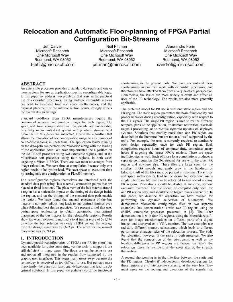
3.1 Relocation Tool-Flow
The complete tool-flow for performing relocation is shown in Figure 5 and includes both compile-time and run-time elements. The inputs required are a description of (some properties of) the Target FPGA and a description of the PR regions that are potential targets. Currently only the Virtex-4 LX and SX chips are supported because we do not have a complete understanding of exactly how the embedded PowerPC on the FX chip series affects the layout of the configuration frames. The FPGA Configuration
Generator computes the pattern of resources and the number of HCLK rows on the target chip. The Adjustment Generator uses this information to compute the run-time parameters required for the actual Relocation of the Bit-streams. These parameters con be compiled-in in the relocation code, or provided as a data file. The relocation algorithm itself is therefore oblivious to the original inputs. Note that the parameters are specific to the FPGA and its PR configuration, which are also static elements in the overall
design. The Adjustment Generator performs some additional checks to verify that the PR regions are relocatable to each other, e.g. that they obey the constraints previously defined. The tool as currently implemented does not check for the bus macro placement constraint, but this can be added later on using the floor-planner tool discussed in Section 4.
3.2 Implementation Constraints
Before we discuss the run-time relocation algorithm, we need to consider a few practical problems that will affect our results.
A set of configuration frames for a column of CLBs can be used as-is in another column of CLBs because it requires the exact
same routing bits and configuration logic bits. This is the good case that we want to obtain at run-time, if at all possible, because the relocation can then proceed at full bus-speed. A more difficult case is when a set of configuration frames is targeted for one side of the chip (ex. top) and the target is at the other side of the chip (ex. bottom). This case requires a bit-reversal of the configuration frames, each frame being over a thousand bits long. The architectural layout of frames on the Virtex-4 chips is such that
frames on the top of the chip are mirror images of the frames on the bottom of the chip. Only the middle word in the frame is not mirrored. This word contains the global routing bits and other configuration data. Bit-reversal means, for example that the bit in position 0 is at position 1311 on the other side of the chip. This requires that the frame is read from end to beginning, because the end of the word in the frame is now the first word that needs to be written to the ICAP port. This can be cumbersome and costly to
do in software. For instance, if the configuration bit-stream is read sequentially from beginning to end, we need to allocate an intermediate storage to buffer one full frame to ensure it is written out in the correct order.
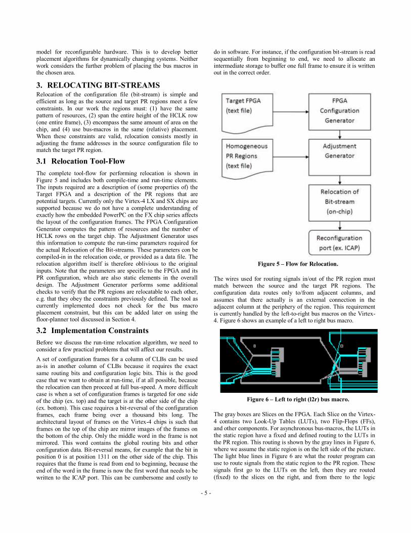
The wires used for routing signals in/out of the PR region must match between the source and the target PR regions. The configuration data routes only to/from adjacent columns, and
assumes that there actually is an external connection in the adjacent column at the periphery of the region. This requirement is currently handled by the left-to-right bus macros on the Virtex-4. Figure 6 shows an example of a left to right bus macro.
The gray boxes are Slices on the FPGA. Each Slice on the Virtex-
4 contains two Look-Up Tables (LUTs), two Flip-Flops (FFs), and other components. For asynchronous bus-macros, the LUTs in the static region have a fixed and defined routing to the LUTs in the PR region. This routing is shown by the gray lines in Figure 6, where we assume the static region is on the left side of the picture. The light blue lines in Figure 6 are what the router program can use to route signals from the static region to the PR region. These signals first go to the LUTs on the left, then they are routed
(fixed) to the slices on the right, and from there to the logic
Figure 6 – Left to right (l2r) bus macro.
Figure 5 – Flow for Relocation.
- 6 -
implemented in the PR region. As long as the bus-macros have the same relative positioning between the two PR regions, this scheme correctly handles the relocatability constraints between PR regions and our algorithm does not have to modify the routing information at all.
For ease and speed of reconfiguration, we decided not to support static routing, e.g. the logic in the static region is not allowed to
route through the PR regions. This can have an adverse effect on the design, for instance when that signal must route to an I/O pin. To handle this requirement, the static routing must either match across all of the PR designs, or we could use the scheme described in [11] and reserve some long lines for the static region inside the PR regions. We prohibited static routing from the PR region by setting the “ROUTING=CLOSED” constraint in the Xilinx ISE. Even though we used this constraint the router would still sometimes inexplicably route through the PR region when trying
to get to the bus macros. To help the router route around the PR region, we created target LUTs to route to before routing to the troublesome bus macros. We used the same approach to handle the case of static logic that mapped to input/output pins near the PR regions. We added a LUT near the I/O pin and designated it as the target for the troublesome I/O signal.
3.3 Relocation Algorithm
Figure 7 shows the algorithm for relocating bit-streams at run-time. There are three possible destinations for a configuration:
1) Destination is where the bit-stream was generated for. No relocation is necessary.
2) Destination is not where it was generated for, but on the same side of the chip. Relocation consists only of the translation of frame addresses.
3) Destination is on the opposite side of the chip. Relocation involves both the translation of the frame addresses and bit-reversal of the frames.
It is actually possible to encounter a combination of cases two and three. The Multiple Frame Write (MFWR) command can write a
single frame of data to multiple frame addresses [15] and this can create a problem. Suppose a bit-stream that is on the top of the chip covering two HCLK rows must relocate to a PR region that straddles the middle of the chip. In the target region, one HCLK is used for both the top and bottom of the chip. A MFWR command could correctly write the same configuration frame to both HCLK rows in the original configuration, but in the new configuration we now need two separate MFWR commands, one for the top and
one for the bottom of the chip. The frame data is valid as-is for the HCLK on the top of the chip, but it must be flipped for the HCLK row on the bottom of the chip. The separation can be done at run-time. The cost is just some additional code because we need to buffer the frame data regardless. It is clearly easier to use a tool that expands the MFWR commands into multiple ones before deploying the bit-stream. Therefore the examples presented in Section 5 do not cover this case.
Based on this algorithm, the three key contributing factors in the time to relocate a bit-stream are (1) the bit-stream size, (2) the bit-stream composition, and (3) the location of the destination PR
region on the chip. By composition we mean the relative count of commands that set the frame address and commands that write configuration frames.
If the stream must be relocated, it would be best if we have very few frame addresses and do not need bit-reversal.
Figure 7 – Relocation Algorithm.
- 7 -
4. POSITIONING THE BUS MACROS The bus macros are the connection points between static and PR
regions, located on the perimeter of the PR regions. The placement process is currently manual; the user selects the location in the instantiated instance of the macro in the HDL source code. There is no guarantee that the placement is optimal, nor any practical way to verify how close to optimal it might be. The best-practices advice is to place inputs to the left, outputs to the right, and use common sense. Letting the macros float only provides limited advice insofar as discovering where the placer
will (want to) locate the static/PR logic that connects to those macros.
We used the following test to measure the quality of the placement of a set of bus macros. Using a design that does not meet timing, we define the “timing score” as the cumulative sum
of the timing errors across all signals that do not meet their timing constraints. This is an indication that is easily obtained from the synthesis reports, and therefore easy to use in an automated setup. Ideally, a design would have a zero score. A negative score is possible (using the slack timing) but harder to compute automatically. Since the timing score is not a precise measure, it is often the case that a design with a positive timing score will actually function correctly. We can always generate a positive score by artificially tightening the timing constraints.
We used a design of the eMIPS processor with a poorly located PR region to test the importance of the placement of the bus macros. This design uses a large number of macros, and therefore provides a fine-grained tool for the evaluation. As shown in Section 5, we observed timing scores in the range of 22,964 to
796,915 picoseconds for various placements. This large spread clearly illustrates the importance of a good placement. At the end of the study we found a second motivation for an automated tool. We inspected the best/worst/manual placements to see if there was any correlation, and to see if we could deduce any guiding principles. We did not find any. The manual placement following best-practices did score better than the average, but still far from the optimal. The optimal design utterly violates all best-practice
rules.
Since the placement is done at the HDL source level, it would appear that it is necessary to re-synthesize each placement from start to finish to be able to evaluate the timing score. For instance, moving a bus macro from the left side to the right side of the PR region requires either a synthesis of the design or a direct
modification of the netlist. We can eliminate this expensive step by using two LUTs instead of a bus macro in the design, and then change the LOC constraint of the two LUTs inside the UCF file. This approach costs the equivalent delay of going through two LUTs, but eliminates the defined routing between them. As an additional benefit, the automated floor-planner can generate placements of the LUTs for whatever side it is currently targeting around the PR region: top, bottom, left, or right. Care was
exercised so that the implementation of the LUTs does not change the logical value of the signal they route.
The bus macro placement is an instance of the more general place-and-route problem, albeit on a much smaller scale. This led to the choice of using simulated annealing to automatically find
the best placement. Our simulated annealing algorithm works by looping over five steps: copy the current solution, alter the copy, evaluate the alternate solution, determine whether to accept the alternate solution as the current solution, and adjust the current temperature. The loop terminates when the cut-off temperature is
reached. Before the loop begins, the algorithm selects an initial temperature and cut-off temperature. The first step copies the current placement of the bus macros from the currently accepted solution. The second step modifies the solution by randomly swapping the positions of the bus macros around the PR region.
The algorithm performs 10 random swaps, which we found was a good balance between elapsed time and spread over the solution space. The third step measures whether the new alternate solution is better than the current accepted solution, using the timing score for the comparison. This timing score is evaluated by running a set of designs that will be used in the PR region through ngdbuild, map, and place and route. This is the most expensive step by far and running every combination of PR configurations would be
prohibitive, so only a few designs were used for our evaluations. The number and type of designs is user-selectable, which leads to a trade-off of time against accuracy of the search. Each design is run in a separate thread to reduce the elapsed of this step. The algorithm can therefore take advantage of multiple processors when they are available in multi-core CPUs. The timing scores from the different designs are combined into one overall score. If the timing score is better than the current solution the new
placement will unconditionally replace the current one. If it is not better, it is accepted with a probability based on the current temperature. The formula used is shown in Equation 1. The fifth and final step decrements the current temperature and breaks out of the loop when it reaches the cutoff temperature.
(1) 𝐴𝑐𝑐𝑒𝑝𝑡 = 𝑒(𝑛𝑒𝑤𝑆𝑐𝑜𝑟𝑒 −𝑐𝑢𝑟𝑆𝑐𝑜𝑟𝑒
𝑇𝑒𝑚𝑝𝑒𝑟𝑎𝑡𝑢𝑟𝑒)< 𝑟𝑎𝑛𝑑𝑜𝑚()
The floor-planner generates an UCF file with the full constraints needed for placing the bus macros. The constraints define on what slice to place the bus macro and the direction: left to right, right to left, top to bottom, or bottom to top. Note that the final solution found by the tool does not need to be synthesized again.
5. RESULTS We present the relocation time required for different target
destinations with an eMIPS and MicroBlaze setup. The results from the floor-planner for the bus macros follow.
To evaluate the relocation algorithm as it applies to the eMIPS processor, we ported the eMIPS design to the ML402 Xilinx board using the larger SX35 chip, and we were then able to instantiate two Extensions. The port required adding some
MUXes into each of the pipeline stages for the second Extension, and in the bus arbiter. As shown in Figure 1, the following modules also required additional signals: pipeline interface, monitoring interface, register interface, and memory bus. The
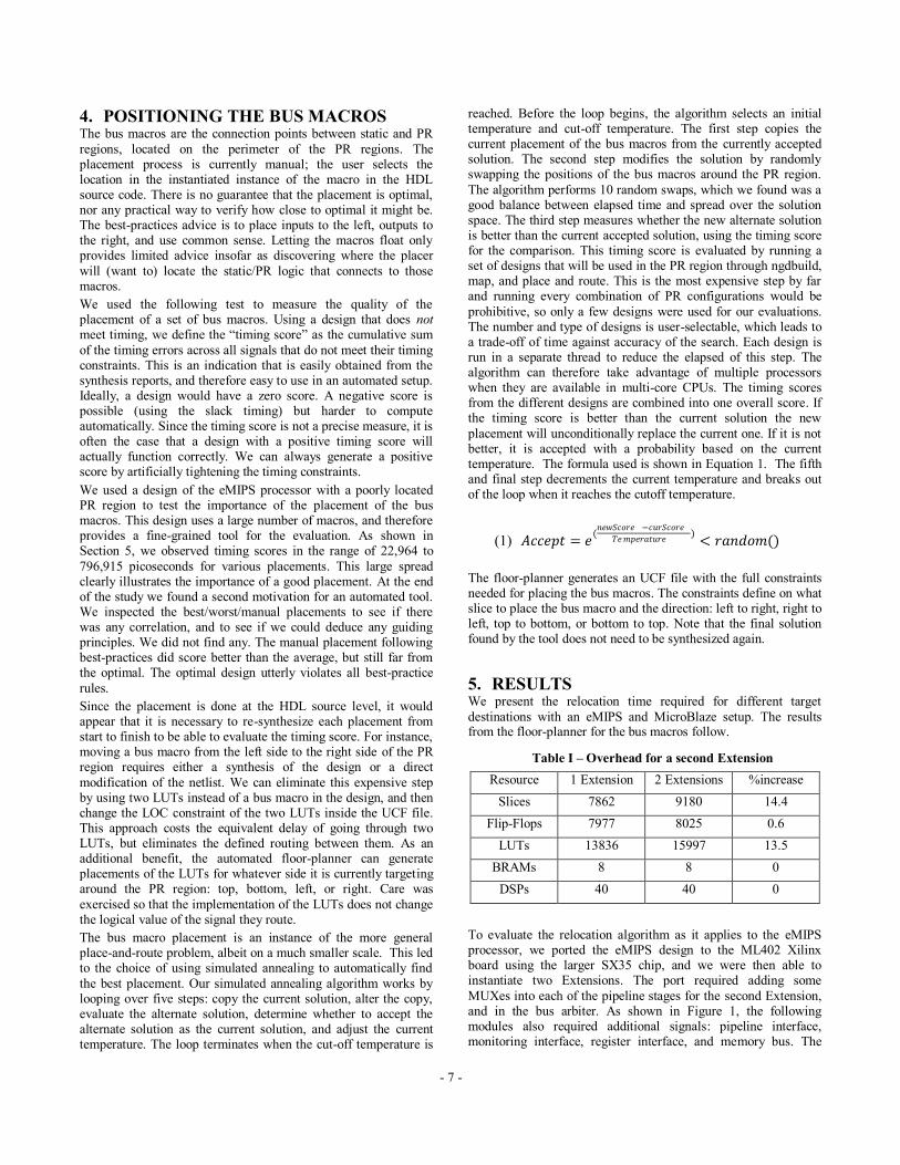
Table I – Overhead for a second Extension
Resource 1 Extension 2 Extensions %increase
Slices 7862 9180 14.4
Flip-Flops 7977 8025 0.6
LUTs 13836 15997 13.5
BRAMs 8 8 0
DSPs 40 40 0
- 8 -
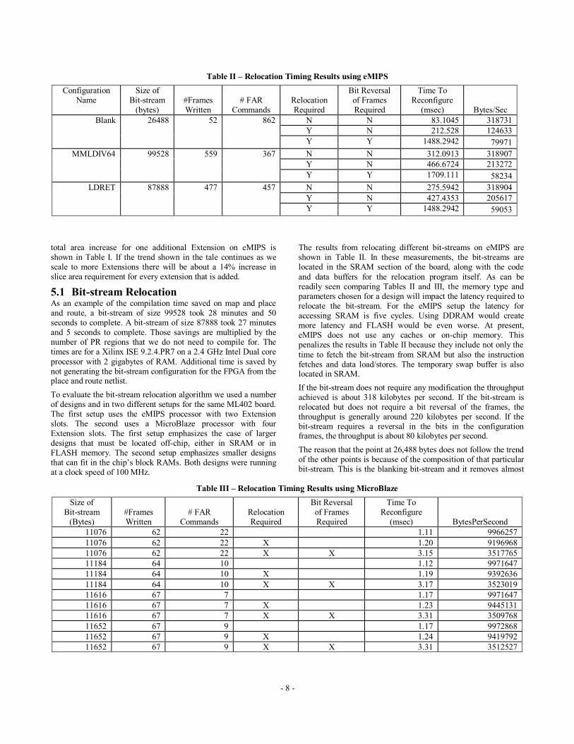
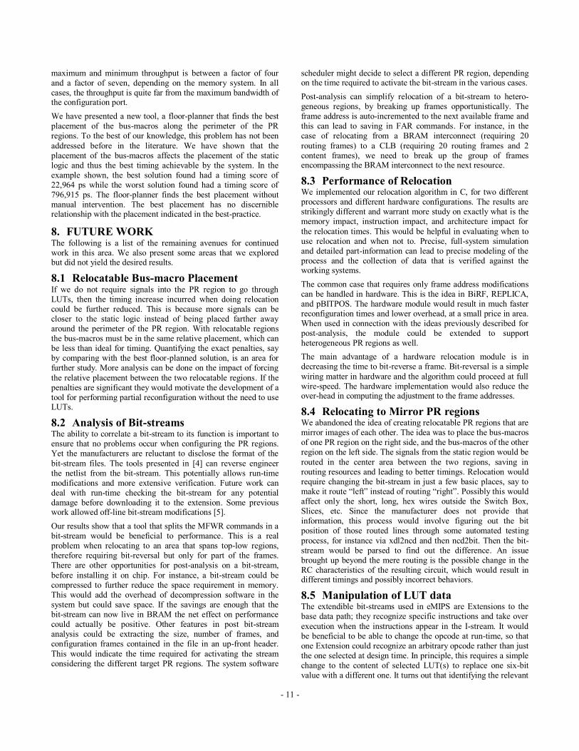
Table II – Relocation Timing Results using eMIPS
Configuration Name
Size of Bit-stream
(bytes) #Frames Written
# FAR Commands
Relocation Required
Bit Reversal of Frames Required
Time To Reconfigure
(msec) Bytes/Sec
Blank 26488
52
862
N N 83.1045 318731
Y N 212.528 124633
Y Y 1488.2942 79971
MMLDIV64 99528
559
367
N N 312.0913 318907
Y N 466.6724 213272
Y Y 1709.111 58234
LDRET 87888
477
457
N N 275.5942 318904
Y N 427.4353 205617
Y Y 1488.2942 59053
Table III – Relocation Timing Results using MicroBlaze
Size of Bit-stream
(Bytes) #Frames Written
# FAR Commands
Relocation Required
Bit Reversal of Frames Required
Time To Reconfigure
(msec) BytesPerSecond
11076 62 22 1.11 9966257
11076 62 22 X 1.20 9196968
11076 62 22 X X 3.15 3517765
11184 64 10 1.12 9971647
11184 64 10 X 1.19 9392636
11184 64 10 X X 3.17 3523019
11616 67 7 1.17 9971647
11616 67 7 X 1.23 9445131
11616 67 7 X X 3.31 3509768
11652 67 9 1.17 9972868
11652 67 9 X 1.24 9419792
11652 67 9 X X 3.31 3512527
total area increase for one additional Extension on eMIPS is shown in Table I. If the trend shown in the tale continues as we scale to more Extensions there will be about a 14% increase in slice area requirement for every extension that is added.
5.1 Bit-stream Relocation As an example of the compilation time saved on map and place and route, a bit-stream of size 99528 took 28 minutes and 50 seconds to complete. A bit-stream of size 87888 took 27 minutes and 5 seconds to complete. Those savings are multiplied by the number of PR regions that we do not need to compile for. The times are for a Xilinx ISE 9.2.4.PR7 on a 2.4 GHz Intel Dual core
processor with 2 gigabytes of RAM. Additional time is saved by not generating the bit-stream configuration for the FPGA from the place and route netlist.
To evaluate the bit-stream relocation algorithm we used a number of designs and in two different setups for the same ML402 board. The first setup uses the eMIPS processor with two Extension slots. The second uses a MicroBlaze processor with four Extension slots. The first setup emphasizes the case of larger designs that must be located off-chip, either in SRAM or in FLASH memory. The second setup emphasizes smaller designs that can fit in the chip’s block RAMs. Both designs were running at a clock speed of 100 MHz.
The results from relocating different bit-streams on eMIPS are shown in Table II. In these measurements, the bit-streams are located in the SRAM section of the board, along with the code
and data buffers for the relocation program itself. As can be readily seen comparing Tables II and III, the memory type and parameters chosen for a design will impact the latency required to relocate the bit-stream. For the eMIPS setup the latency for accessing SRAM is five cycles. Using DDRAM would create more latency and FLASH would be even worse. At present, eMIPS does not use any caches or on-chip memory. This penalizes the results in Table II because they include not only the
time to fetch the bit-stream from SRAM but also the instruction fetches and data load/stores. The temporary swap buffer is also located in SRAM.
If the bit-stream does not require any modification the throughput achieved is about 318 kilobytes per second. If the bit-stream is relocated but does not require a bit reversal of the frames, the throughput is generally around 220 kilobytes per second. If the bit-stream requires a reversal in the bits in the configuration frames, the throughput is about 80 kilobytes per second.
The reason that the point at 26,488 bytes does not follow the trend of the other points is because of the composition of that particular bit-stream. This is the blanking bit-stream and it removes almost
- 9 -
Figure 8 – History of current solutions at end of iteration.
Figure 9 – History of alternate scores.
all the routing that was done in the PR region, which results in a large number of matching configuration frames. The bit-stream issues a large amount of MFWR commands to write the same configuration frame to multiple frame addresses. This bit-stream therefore contains an unusually large concentration of frame
addresses relative to its size. For comparison, the bit-stream of size 87,888 has only 457 frame address commands compared to 862 for the blanking bit-stream. This decreases the throughput for the relocation with no bit reversal because of the increased calls to translate the frame addresses. Similarly, this bit-stream performs better than average for the relocation with bit reversal of frames because it contains a low concentration of configuration frames compared to a bit-stream of size 11,652. This results in reducing
the penalty of calling the bit-reversal function. The no modification throughput for all the different bit-streams is approximately the same. This is expected since the algorithm is just copying the bit-stream to the ICAP without any modification.
The results from relocating on the MicroBlaze setup (Figure 3) are shown in Table III. In this case, all of the bit-streams, code and
data buffers are located in BRAM on the chip, which is 32-bit wide and accessible in a single cycle. If the bit-stream does not
require modification the throughput achieved is about 10 megabytes per second. If the bit-stream is relocated but does not require a bit reversal of the frames, the throughput is between 9.2 to 9.5 megabytes per second. If the bit-stream requires a bit-reversal of the configuration frames, the throughput is about 1.4 megabytes per second.
The ICAP port accepts one write per cycle, and in both experiments it was configured in a 32-bit width. Since the designs are run at 100 MHz, the maximum achievable throughput is 400 megabytes per second. The BRAMs provide the same throughput. A detailed analysis of exactly how the memory, architecture, and
especially the software contribute to the reduction from the maximum throughput is beyond the limits of this study.
5.2 Floor-planning of the Bus Macros We ran the floor-planner using the eMIPS design, with two Extension slots targeted for an SX35 chip. Each PR region requires 71 bus macros to communicate with the static region. This number of bus macros is large enough for the design space exploration, but we make no claim of it being a good
representative of the average PR design. Other projects using PR regions will use more or less bus macros, depending on the
required amount of communication between the static logic and the PR region. For example, the MicroBlaze example with 4 PR regions uses 3 bus macros for each PR region. In the experiments, the location of the PR regions was fixed and the timing constraints were constants. The initial placement of the bus macros was
randomly generated. The algorithm ran a total of 280 iterations. We used two different PR designs for the timing analysis. The first design was the load/return Extension which would be impacted by the placement of the memory interface bus macros. The other design was the mmldiv Extension because it covered all the bus macros that the load/return Extensions did not use. The time required for ngdbuild, map, place and route of the two designs was about 6-8 minutes with normal effort for place and
route. The algorithm therefore takes about 10 minutes per iteration. When using high effort for place and route this time doubles. We choose not to use high effort in order to perform more iterations, and to only select high effort starting from the
best placement to better meet timings. All times are for Xilinx ISE 10.1.02 on a 2.4 GHz Intel Dual core processor with 2 gigabytes of RAM.
The history of the currently accepted solutions is shown in Figure 8. The full history, including the alternate scores is shown in Figure 9. The results show that there is wide variance between the scores depending on how the bus macros are placed. The average score in the design space was 175,682 ps. Different bus
macro placements have noticeable effects on the timings. The worst solution had a total score of 796,915 ps while the best solution had a score of 22,964 ps. The original (manual) placement for the design had a score of 97,714 ps. The timing constraints used can be changed based on the desired optimization the user wants the floor-planner to head towards. The original placement had a max period for ld/return of 9.902ns and for mmldiv of 10.120ns. The best solution found had a max period for
ld/return of 9.919ns and for mmldiv of 9.611ns. Turning back on high effort would yield better results for the timing score. This layout has a positive effect on the max frequency that can be used in the system. For timing critical designs this tool will help meet timing constraints and enable higher frequencies of the design due to better placement.
Figure 10 shows the original placement given for the bus macros around the PR region. Figure 11 shows the best placement found by the tool. There are no bus macros around the top of the PR region because in this design the region is located at the top of the chip, leaving no room for placement of any static logic. The bus
- 10 -
Figure 11 – Best bus macro placement.
Figure 10 – Manual bus macro placement.
macro naming convention used in Figure 10 and Figure 11 is I/O, macro number, and then 0-n for the number of macros needed for the bus width, each macros carrying a maximum of 8 signals. For example a 32-bit input bus signal used macros I0-0, I0-1, I0-2, and I0-3. A 32-bit output bus signal used macros O3-0, O3-1, O3-
2, and O3-3. In Figure 11, the best solution placement does not group the bus signals near each other. This makes it hard to figure out the best placement by hand as there is no observable pattern to the best layout. For example, in Figure 11 the bus signals for O2 are on the left, bottom, and upper-right of the chip. This demonstrates the challenge the designer would have to face to find the best placement and consequently the best timings. Note that when using actual bus macros it is necessary to express at the
HDL level on which side of the PR region the bus macro must be located. Each combination then requires manual changes to the UCF file. On the other hand, trying to follow the pattern observed in Figure 11 for other designs seems impractical.
6. LIMITATIONS The bit-stream relocation program currently does not generate the
CRC values at the end of the stream. The CRC checker can be disabled post-bit-stream generation, or by adding in some options with the “POST_CRC*” constraints in the UCF file. Not generating a new CRC value for the partial bit-streams had no effect on the configuration taking place for the ML401 and ML402 boards used for testing.
The floor-planner currently only handles asynchronous bus macros. Adding support for synchronous bus macros requires handling flip-flops as well. The tool requires some additional user input to identify the bus macros from the UCF file. Currently the user must manually update the HDL code with the new directions
for the bus macros found by the tool. Future work seeks to reduce and eliminate these requirements from the user.
The 280 iterations we ran took 41 hours on a 2.4 GHz Intel Dual core processor with 2 gigabytes of RAM. This means that even simple changes in the interfaces would require a day or so before the new placement of the bus macros is found. This effectively limits the use of the placement algorithm to designs that are stable enough to be ready for optimization.
7. CONCLUSIONS We have shown that relocatable bit-streams are beneficial in two dimensions: they reduce the number of bit-streams stored on a
deployed system and they save compilation time during development. Both savings scale linearly with the number of PR regions used in a system.
We have presented an on-chip algorithm and the corresponding tool-flow for performing bit-stream relocation. The algorithm was implemented and evaluated in two different architectures, leading to different performance numbers. In both cases, the content and destination of the bit-stream have the same and very noticeable effect on the maximum achieved throughput. The span between
- 11 -
maximum and minimum throughput is between a factor of four and a factor of seven, depending on the memory system. In all cases, the throughput is quite far from the maximum bandwidth of the configuration port.
We have presented a new tool, a floor-planner that finds the best placement of the bus-macros along the perimeter of the PR regions. To the best of our knowledge, this problem has not been
addressed before in the literature. We have shown that the placement of the bus-macros affects the placement of the static logic and thus the best timing achievable by the system. In the example shown, the best solution found had a timing score of 22,964 ps while the worst solution found had a timing score of 796,915 ps. The floor-planner finds the best placement without manual intervention. The best placement has no discernible relationship with the placement indicated in the best-practice.
8. FUTURE WORK The following is a list of the remaining avenues for continued work in this area. We also present some areas that we explored but did not yield the desired results.
8.1 Relocatable Bus-macro Placement If we do not require signals into the PR region to go through LUTs, then the timing increase incurred when doing relocation could be further reduced. This is because more signals can be closer to the static logic instead of being placed farther away around the perimeter of the PR region. With relocatable regions the bus-macros must be in the same relative placement, which can be less than ideal for timing. Quantifying the exact penalties, say by comparing with the best floor-planned solution, is an area for further study. More analysis can be done on the impact of forcing
the relative placement between the two relocatable regions. If the penalties are significant they would motivate the development of a tool for performing partial reconfiguration without the need to use LUTs.
8.2 Analysis of Bit-streams The ability to correlate a bit-stream to its function is important to ensure that no problems occur when configuring the PR regions. Yet the manufacturers are reluctant to disclose the format of the
bit-stream files. The tools presented in [4] can reverse engineer the netlist from the bit-stream. This potentially allows run-time modifications and more extensive verification. Future work can deal with run-time checking the bit-stream for any potential damage before downloading it to the extension. Some previous work allowed off-line bit-stream modifications [5].
Our results show that a tool that splits the MFWR commands in a bit-stream would be beneficial to performance. This is a real problem when relocating to an area that spans top-low regions, therefore requiring bit-reversal but only for part of the frames. There are other opportunities for post-analysis on a bit-stream,
before installing it on chip. For instance, a bit-stream could be compressed to further reduce the space requirement in memory. This would add the overhead of decompression software in the system but could save space. If the savings are enough that the bit-stream can now live in BRAM the net effect on performance could actually be positive. Other features in post bit-stream analysis could be extracting the size, number of frames, and configuration frames contained in the file in an up-front header.
This would indicate the time required for activating the stream considering the different target PR regions. The system software
scheduler might decide to select a different PR region, depending on the time required to activate the bit-stream in the various cases.
Post-analysis can simplify relocation of a bit-stream to hetero-geneous regions, by breaking up frames opportunistically. The frame address is auto-incremented to the next available frame and this can lead to saving in FAR commands. For instance, in the case of relocating from a BRAM interconnect (requiring 20
routing frames) to a CLB (requiring 20 routing frames and 2 content frames), we need to break up the group of frames encompassing the BRAM interconnect to the next resource.
8.3 Performance of Relocation We implemented our relocation algorithm in C, for two different processors and different hardware configurations. The results are strikingly different and warrant more study on exactly what is the memory impact, instruction impact, and architecture impact for
the relocation times. This would be helpful in evaluating when to use relocation and when not to. Precise, full-system simulation and detailed part-information can lead to precise modeling of the process and the collection of data that is verified against the working systems.
The common case that requires only frame address modifications can be handled in hardware. This is the idea in BiRF, REPLICA, and pBITPOS. The hardware module would result in much faster reconfiguration times and lower overhead, at a small price in area. When used in connection with the ideas previously described for post-analysis, the module could be extended to support heterogeneous PR regions as well.
The main advantage of a hardware relocation module is in decreasing the time to bit-reverse a frame. Bit-reversal is a simple
wiring matter in hardware and the algorithm could proceed at full wire-speed. The hardware implementation would also reduce the over-head in computing the adjustment to the frame addresses.
8.4 Relocating to Mirror PR regions We abandoned the idea of creating relocatable PR regions that are mirror images of each other. The idea was to place the bus-macros of one PR region on the right side, and the bus-macros of the other region on the left side. The signals from the static region would be
routed in the center area between the two regions, saving in routing resources and leading to better timings. Relocation would require changing the bit-stream in just a few basic places, say to make it route “left” instead of routing “right”. Possibly this would affect only the short, long, hex wires outside the Switch Box, Slices, etc. Since the manufacturer does not provide that information, this process would involve figuring out the bit position of those routed lines through some automated testing
process, for instance via xdl2ncd and then ncd2bit. Then the bit-stream would be parsed to find out the difference. An issue brought up beyond the mere routing is the possible change in the RC characteristics of the resulting circuit, which would result in different timings and possibly incorrect behaviors.
8.5 Manipulation of LUT data The extendible bit-streams used in eMIPS are Extensions to the base data path; they recognize specific instructions and take over
execution when the instructions appear in the I-stream. It would be beneficial to be able to change the opcode at run-time, so that one Extension could recognize an arbitrary opcode rather than just the one selected at design time. In principle, this requires a simple change to the content of selected LUT(s) to replace one six-bit value with a different one. It turns out that identifying the relevant
- 12 -
LUTs that compare the opcode is troublesome. We need a lot of chip-specific information at run-time just to know what frame we are currently at. Then we need to get the offsets of the LUTs in the frame. The .ll file can do this, but only for the LUTs in Slice M (i.e. must set it up in RAM/ROM mode). It would therefore
seem that only the ncd file can tell us where those specific LUTs are located. If we cannot deduce that information from the bit-stream it means that we have to trust the bit-stream blindly, which is not ideal.
We tried to identify exactly what INIT values to send to a LUT to change its function. The problem that we encountered was that the inputs to the LUTs are rearranged into a different order, even for small differences. This allows the fastest throughput through the circuit as not all inputs are equal in delay. This makes it harder to correlate a LUT’s value with the value found in the bit-stream.
8.6 Floor-planning of Bus-Macros The tool we built has a relatively high cost in execution time. Lowering this cost would make it more widely usable and/or allow us to use a larger number of designs to find the best placement. One idea for creating a faster method in the common case of homogeneous regions is as follows. Rather than working at the UCF level, start at the Verilog level. One immediate advantage over our approach is that there is more freedom in selecting which signals are grouped into a bus macro, because we
no longer operate at the granularity of a LUT. We can create an area group constraint around the boundary of the PR region. The Xilinx tools run post place and route. The routed file is converted back to XDL. The automated tool uses the XDL file to create the bus macros and slice locations. This requires a single iteration and should immediately get a good placement for the bus macros. When used on different designs that target the same PR region the issue is then to match the bus-macro locations across all regions.
If we allow complete freedom in grouping signals into bus macros, the optimal placement will likely create bus macros that carry both input and output signals. This is not currently
supported and requires the creation of new bus-macros, for instance using the tools described in[6]. Further work is also needed to add support for synchronous bus macros.
It was suggested that we try to group even more signals together in the floor-planner tool. For instance, when placing the bus-macros for a 32-bit bus it might be advantageous to group signals at more than the LUT granularity. As shown in Figure 11, the best placement does not actually group bus signals together. This discourages the idea that better results would be obtained by keeping them together as they did not tend to cluster near each
other in the best placement found by the tool. Work is needed to prove or disprove this point.
8.7 Simulated Annealing We can improve on the simulated annealing algorithm used in the floor-planner. One idea is to make alterations at the single signal granularity rather than at the bus-macro granularity. This would allow greater flexibility in finding the adjustment closest to the optimal solution.
We can try different number of swaps per iteration as well as different initial and cutoff temperatures. The goal is to reach a closer approximation of the optimal solution in a shorter time. We
can also scale down the number of swaps performed in a step, based on the current temperature. For instance, a smaller number of swaps at lower temperatures might improve the final score.
It might turn out that the best choice for how many swaps and the initial and cutoff temperatures are dependent on some general properties of the designs used by the user. If that is the case the tool should become more flexible for greater applicability.
8.8 PR Region Placement We have assumed that the location of the PR region was an input to the bus-macro placer. This is often not the case and designers select that placement in an arbitrary way too. An important addition to the tool flow is therefore a tool to find the best location for the relocatable regions. The tool would be run first to determine the best on-chip placement for the PR region, then the bus macro floor-planner. The ideas presented in [16] could select the optimal area, but making sure we only find areas that are easily relocatable to each other.
8.9 Virtex-5 Relocation and Bus Macros Our work so far has been restricted to the Virtex-4 FPGAs. We have used two LUTs and LOC constraints in the UCF file to automatically place the bus-macros. Reference [6] shows an alternative approach, namely using XDL to create the Xilinx bus-macros. Future work could be creating new bus-macros for the
Virtex-5 FPGA in order to extend our tool to that chip. Additional work using this approach could assure that routing in/out of the PR region is coherent among all the different PR regions.
8.10 Arcs.Exclude Format The process described in [11] allows static routing in the PR region. We have explored the idea of combining the static routing restrictions from different PR regions into a single target PR region. We would use the arcs.exclude file that is part of the
Xilinx flow to enforce the restrictions. Unfortunately, the format of that file is also not documented and it does not follow an easily recognizable logic. This makes it impossible to relocate the excluded routed lines from one PR region to another PR region.
[2] Becker, T.; Luk, W.; Cheung, P.Y.K., "Enhancing Relocatability of Partial Bit-streams for Run-Time Reconfiguration," Field-Programmable Custom Computing Machines, 2007. FCCM 2007. 15th Annual IEEE Symposium on, vol., no., pp.35-44, 23-25 April 2007.
[3] Montminy, D.P.; Baldwin, R.O.; Williams, P.D.; Mullins, B.E., "Using Relocatable Bit-streams for Fault Tolerance," Adaptive Hardware and Systems, 2007. AHS 2007. Second NASA/ESA Conference on, vol., no., pp.701-708, 5-8 Aug. 2007.
[4] Note, J. and Rannaud, É. 2008. From the bit-stream to the netlist. In Proceedings of the 16th international ACM/SIGDA Symposium on Field Programmable Gate Arrays (Monterey, California, USA, February 24 - 26, 2008). FPGA '08. ACM, New York, NY, 264-264.
[5] Guccione, S., Levi, D. and Sundararajan, P. “JBits: Java based interface for reconfigurable computing”, Xilinx Inc, San Jose, CA
[6] C. Claus, B. Zhang, M. Huebner, C. Schmutzler, J. Becker,
W. Stechele, "An XDL-based busmacro generator for customizable communication interfaces for dynamically and
partially reconfigurable systems", Workshop on Reconfigurable Computing Education at ISVLSI 2007, Porto Alegre, Brazil, May 12, 2007.
[7] Horta, E.L.; Lockwood, J.W.; Taylor, D.E.; Parlour, D., "Dynamic hardware plugins in an FPGA with partial run-time reconfiguration," Design Automation Conference, 2002. Proceedings. 39th , vol., no., pp. 343-348, 2002.
[8] Pittman, R. N., Lynch, N. L., Forin, A. eMIPS, A Dynamically Extensible Processor, MSR-TR-2006-143, Microsoft Research, WA, October 2006.
[9] Download at http://research.microsoft.com/research/EmbeddedSystems/eMIPS/eMIPS.aspx
[10] Kane, G., Heinrich, J. 1992. MIPS RISC Architecture. Prentice Hall, Upper Saddle River, NJ.
[11] Sedcole, P.; Blodget, B.; Becker, T.; Anderson, J.; Lysaght, P., "Modular dynamic reconfiguration in Virtex FPGAs," Computers and Digital Techniques, IEE Proceedings - , vol.153, no.3, pp. 157-164, 2 May 2006.
[12] Kalte, H.; Lee, G.; Porrmann, M.; Ruckert, U., "REPLICA: A Bit-stream Manipulation Filter for Module Relocation in
Partial Reconfigurable Systems," Parallel and Distributed Processing Symposium, 2005. Proceedings. 19th IEEE International , vol., no., pp. 151b-151b, 04-08 April 2005.
[13] Ferrandi, F., Novati, M., Morandi, M., Santambrogio, M. D., Sciuto, D. "Dynamic Reconfiguration: Core Relocation via Partial Bit-streams Filtering with Minimal Overhead," System-on-Chip, 2006. International Symposium on , vol., no., pp.1-4, Nov. 2006.
[14] Krasteva, Y.E.; de la Torre, E.; Riesgo, T.; Joly, D., "Virtex II FPGA Bit-stream Manipulation: Application to
Reconfiguration Control Systems," Field Programmable Logic and Applications, 2006. FPL '06. International Conference on , vol., no., pp.1-4, 28-30 Aug. 2006.
[15] Xilinx Inc. Virtex-4 Configuration Guide v1.10, April 2008.
[16] Singhal, L.; Bozorgzadeh, E., "Multi-layer Floor-planning on a Sequence of Reconfigurable Designs," Field
Programmable Logic and Applications, 2006. FPL '06. International Conference on , vol., no., pp.1-8, 28-30 Aug. 2006.
[17] Koester, M.; Porrmann, M.; Ruckert, U., "Placement-Oriented Modeling of Partially Reconfigurable Architectures," Parallel and Distributed Processing Symposium, 2005. Proceedings. 19th IEEE International , vol., no., pp. 164b-164b, 04-08 April 2005.
[18] Xilinx Inc. MicroBlaze Processor Reference Guide. URL: http://www.xilinx.com/support/documentation/sw_manuals/mb_ref_guide.pdf.