21
JANUARY 2015 RENEWABLE ENERGY SUB-CODE for Distribution Network connected Variable Renewable Energy Power Plants in Ghana

i
JANUARY 2015
RENEWABLE ENERGY
SUB-CODE for Distribution Network connected Variable
Renewable Energy Power Plants in Ghana

i
Table of Content
PART A: 1 1 Introduction 1
1.1 Scope 1 1.2 Status 1 1.3 Terms and Definitions 2
PART B: 6 2 Technical Connection Conditions 6
2.1 General 6 2.2 Frequency Range of Operation 6 2.3 Voltage Range of Operation 7 2.4 Power Quality 7
2.4.1 Rapid Voltage Changes 8 2.4.2 Flicker 8 2.4.3 Voltage Unbalance 8 2.4.4 Harmonics 8
2.5 Reactive Power Capability 9 2.6 Reactive Power Control Requirements 11
2.6.1 General 11 2.6.2 Reactive Power Control (Q Control) 11 2.6.3 Power Factor Control (Cosφ-Control) 12
2.7 Active Power Control 12 2.8 Frequency Response 12
2.8.1 High Frequency Response for VRPPs 12 2.8.2 Primary and Secondary Frequency Control 13
2.9 Behaviour during Abnormal Voltage Conditions 14 2.9.1 Low Voltage Ride Through (LVRT) / High Voltage Ride Through (HVRT) Capability for VRPPs 14 2.9.2 Reactive Current Support During LVRT/HVRT Situations 14 2.9.3 Active and Reactive Power Behaviour During Voltage Recovery 15
2.10 Automatic Resynchronisation 16 2.11 Protection and Fault Levels 16 2.12 Communication and Control 16
PART C: 17 3 Testing, Inspection and Compliance Monitoring 17
RENEWABLE ENERGY SUB-CODE – DISTRIBUTION
ii
List of Tables
Table 1: Frequency Ranges of Operation (Must remain connected conditions) 6 Table 2: Flicker limits to be applied in the absence of apportioned limits 8 Table 3: Current distortion limits for DN connected VRPPs 9
List of Figures
Figure 1: Maximum Active Power Capability in Function of Frequency 7 Figure 2: Reactive power requirements for DN connected VRPPs (corresponding to voltage) 10 Figure 3: Reactive power requirements for DN connected VRPPs at full and partial active power output conditions
10 Figure 4: Reactive power control function of DN connected VRPP (const Q-control and Q(P)-control) 11 Figure 5: Mandatory high frequency response for all DN connected VRPPs 13 Figure 6: LVRT and HVRT capability for DN connected VRPPs 14 Figure 7: Reactive current support ΔIq during LVRT and HVRT situations at the unit’s terminals 15
Measurement
W Watt Wp Watt peak Wh Watt hour
kW Kilowatt kWp Kilowatt peak kWh Kilowatt hour
MW Megawatt MWp Megawatt peak MWh Megawatt hour
GW Gigawatt GWp Gigawatt peak GWh Gigawatt hour

RENEWABLE ENERGY SUB-CODE – DISTRIBUTION
iii
List of Acronyms
DN Distribution Network
DU Distribution Utility
ETU Electricity Transmission Utility
IEC International Electro-technical Committee
MV Medium Voltage
NITS National Interconnected Transmission System
POC Point of Connection
TN/TS Transmission Network/ Transmission System
VRPP
Variable Renewable Power Plant

RENEWABLE ENERGY SUB-CODE – DISTRIBUTION
1
PART A:
1 Introduction
The Republic of Ghana seeks to develop, manage and utilize renewable energy sources in an effective and
environmentally suitable manner for the production and distribution of electricity in accordance with the Renewable
Energy Act, 2011 (Act 832). This requires guidelines to facilitate the connection of variable renewable energy sources
to a Distribution Network without affecting the secured operation of transmission or distribution networks in Ghana.
This Renewable Energy Sub-Code proposes minimum technical connection conditions for a Variable Renewable
Power Plant (VRPP) or Embedded Generator to the Distribution Network. This Sub-Code is in line with National
Electricity Distribution Code and international best practices and standards.
A VRPP applicant seeking connection to a Distribution Network with a nominal voltage greater than 1kV shall comply
with this Sub-Code and all applicable articles of the National Electricity Distribution Code.
1.1 Scope
This Renewable Energy Sub-Code constitutes the basic technical performance requirements that a VRPP needs to
comply with in order to connect its generating facility to a Distribution Network in Ghana and defines rules and
standards that the network operators shall follow when connecting a VRPP to its Distribution Network.
(1). Compliance with this Sub-Code is meant to ensure safe, reliable and secure operation of all VRPPs connected
to Distribution Networks.
(2). The basic technical performance requirements provided in this Sub-Code applies to all VRPPs connected to
voltage levels greater than 1 kV and up to 36 kV (medium voltage network).
(3). The Distribution Utility (DU) and a VRPP operator shall supply each other with the necessary data and
information about their network or plant that is required for ensuring compliance with this Sub-Code and if
required, the DU shall facilitate the arrangement for a VRPP operator to contact Electricity Transmission
Utility (ETU) for additional information.
1.2 Status
This Sub-Code constitutes an Addendum to the National Electricity Distribution Code.
RENEWABLE ENERGY SUB-CODE – DISTRIBUTION
2
1.3 Terms and Definitions
Available generation capacity
It is the maximum actual generation capacity of the generator unit that could be generated stably and
continuously in the determined period.
Capability Curve
A curve developed for generators showing the limits of reactive and active power that a generator can produce
without overheating or becoming unstable.
Connection Agreement
It is an agreement between the DU and a Grid Participant that seeks connection of its facilities to the NITS
and sets out the rights, obligations and liabilities of both parties.
Connection point
The point of physical linkage to or with the Distribution Network for the purpose of enabling the flow of
electricity as the boundary between the Distribution Network and a facility or other equipment.
Continuous Operation
Network operating frequency or voltage range, outside normal range of operation, within which no
generating unit is allowed to disconnect.
Distribution Network (DN)
In this Sub-Code in relation to a Distribution Utility, DN
means a system of electric lines and associated equipment (at nominal voltage levels of 1 kV up to 36 kV),
which that Distribution Utility is licensed to use to distribute electricity for supply under its distribution
licence excluding public lighting assets.
Distribution Company
A person licensed under the Energy Commission Act, 1997 (ACT 541) to distribute and sell electricity without
discrimination to consumers in an area or zone designated by the Board of the Energy Commission.
Distribution Utility (DU)
Electricity Distribution Company licensed by the Energy Commission that operates the distribution network to provide services in accordance with the Performance and Reliability Standards of the National Electricity Distribution Code.
Disturbance
An unplanned event that produces an abnormal system condition or any occurrence that adversely affects
normal power flow in a system.
Echo
In relation to park control system, it is the signal that is sent from a VRPP to the communication system of
the network operator.
Electricity Transmission Utility (ETU)
The entity mandated by the Energy Commission Act, 1997 (ACT 541) to operate the National Interconnected
Transmission System (NITS) to provide services in accordance with the Performance and Reliability
Standards of the National Electricity Grid Code.

RENEWABLE ENERGY SUB-CODE – DISTRIBUTION
3
Emergency
Any abnormal system condition that requires automatic or immediate manual action to prevent or limit loss
of generation supply or transmission facilities that could adversely affect the reliability of the electric system.
Frequency control
The retention of the frequency on the power system within acceptable limits.
Frequency regulation
The automatic adjustment of active power output by a generation unit, initiated by fast acting frequency
controller action in response to continuous minor fluctuations of frequency on the power system.
Flicker
A fast fluctuation in voltage leading to quick intermittent coming on, of an appliance and gives the impression
of unstable visual sensation induced by a light stimulus with luminance or spectral distribution that
fluctuates with light.
Generating unit
An equipment or plant for producing electrical energy from other forms of energy.
Generation facility
A facility comprising of generators for producing electric energy from other forms of energy expressed in
watt-hours (Wh).
Grid Participant
A Wholesale Supplier or a VRPP facility owner or Bulk Customer with facilities that are connected to the DN.
Harmonics
A sinusoidal wave having a frequency that is an integral multiple of a fundamental frequency.
Interconnected system
It is a system consisting of two or more individual electric systems that normally operate in synchronism and
that have connecting tie-lines.
Individual Harmonic Distortion
IHD is the ratio between RMS value of the individual harmonic content and the RMS value of the
fundamental voltage expressed in percentage.
𝐼𝐻𝐷 = √𝑉𝑖
2
𝑉12 ∗ 100 %
Vi = Voltage component of harmonic order i;
V1 = Voltage component of fundamental frequency (50 HZ).
Island
A portion of a power system or several power systems that is electrically separated from the inter-connection
due to the disconnection of distribution network equipment.
National Interconnected Transmission System
Incorporates all equipment which form part of the national interconnected transmission system irrespective
of ownership or whether it is dedicated to the service of an entity.
RENEWABLE ENERGY SUB-CODE – DISTRIBUTION
4
Nominal Voltage
The voltage by which the system is designated and to which certain operating characteristics are related, and
the voltage at which the system operates and is normally about 5 to 10 percent below the maximum system
voltage for which system components are designed.
Operating reserve
The additional megawatt output required from a generation unit or demand reduction which must be
realizable in real time operation to contain and correct any potential power system frequency deviation to an
acceptable level.
Point of Connection (POC)
Point on a public power supply system where the installation under consideration is, or can be connected.
Note: A supply system is considered as being public in relation to its use, and not its ownership.
Ramp rate
The rate of change at which the power output of a generator can be increased or decreased (in MW/min)
Single contingency
Includes the singular that involves,
(a). …sudden, unexpected failure or outage of any single component of a power system, like generating
unit, transmission line, transformer, etc.; or
(b). …removal from service of an element of the power system like generating unit, transmission line,
transformer etc. as part of the operation of a remedial action scheme, the occurrence of which shall
not affect the normal operation of the NITS.
Synchronize
The process of connecting two previously separated alternating current apparatuses after matching
frequency, voltage and phase angles like paralleling a generator to the electric system.
System Protection Dependability
A measure of the ability of protection to initiate successful tripping of circuit-breakers which are associated
with a faulty item of apparatus. It is calculated by using the formula:
Dp = 1-F1/A
Where: A = Total number of faults
F1 = Number of system faults where there was a failure to trip a circuit breaker.
Total Harmonic Distortion
THD shall be defined as the ratio of the RMS voltage of the harmonic content to the RMS value of the
fundamental voltage, expressed in percent.
𝑇𝐻𝐷 = √∑ 𝑉𝑖
2
𝑉12 ∗ 100 %
THD = Total Harmonic Distortion of voltage;
Vi = Voltage component of harmonic order i;
V1 = Voltage component of fundamental frequency (50 HZ).
RENEWABLE ENERGY SUB-CODE – DISTRIBUTION
5
Transmission System/Transmission Network
An interconnected group of electric transmission lines and associated equipment for moving or transferring
electric energy in bulk between points of supply and points at which it is transformed for delivery over the
distribution system lines to consumers, or to other electric systems.
Unrestricted Operation Range
Normal network frequency or voltage operating range during which no generating unit is allowed to
disconnect and where there is no technical restriction with regard to the delivery of active power or reactive
power.
Variable Renewable Power Plant
Renewable power plants with continuously varying power output following the availability of primary energy
without any storage (Wind and PV farms).
Voltage regulatory system
A centralized control system at a VRPP that measures voltage compared to a set point voltage and
controls reactive power devices.
VRPP owner
The owner of a generation facility or an independent power producer seeking to interconnect their facility
with DN.
VRPP operator
Operator of a VRPP seeking connection to or already connected to the DN.
Wholesale Supplier
A person licensed under the Energy Commission Act, 1997 (Act 541) to install and operate a facility to procure
or produce electricity for sale to a bulk customer or to a distribution company for distribution and sale to
consumers.

RENEWABLE ENERGY SUB-CODE – DISTRIBUTION
6
PART B:
2 Technical Connection Conditions
2.1 General
In the implementation of this Sub-Code, the following general rules shall apply:
(1). The interconnection of a VRPP with the DN shall not deteriorate system security.
(2). A VRPP shall meet the requirements of this guideline at the POC unless otherwise specified in this document
or by the DU.
(3). The design, installation, commissioning, maintenance and operation of the generation facility shall be
conducted in a manner that ensures safety and security of a VRPP, DN and NITS.
(4). A VRPP owner or operator shall maintain and operate power plants in accordance with the instructions of
the ETU/DU to supply electricity through DN to consumers.
(5). A VRPP or any other generator or consumer connected to the DN shall be responsible for protecting its
equipment in such a manner that faults or other disturbances in the NITS or DN do not cause damage to
their equipment.
(6). DU shall not assume any responsibility for the protection of a VRPP’s plant or any other generator or
consumer or equipment or any other portion of the VRPP’s electrical equipment. A Grid Participant shall be
responsible for protecting its equipment in such a manner that faults or other disturbances in the NITS or
DN do not cause damage to the Grid Participant’s equipment.
(7). A VRPP shall at all times comply with applicable requirements and conditions of connection for generating
units and in accordance with any Connection Agreement with the DU.
(8). A VRPP owner/operator shall permit and arrange participation in the inspection, testing or commissioning
of facilities and equipment to be connected to the DN.
2.2 Frequency Range of Operation
(1). A VRPP shall be capable of staying connected within the frequency ranges and times specified in Table 1.
Table 1: Frequency Ranges of Operation (Must remain connected conditions)
Frequency (Hz) Operation
47.5 ≤ F < 48.75 90 Minutes
48.75 ≤ F < 51.25 Unlimited (Continuous Range)
51.25 < F ≤ 51.5 90 Minutes
51.5 < F ≤ 52 15 Minutes
(2). In case of frequencies outside the frequency and time ranges specified in A VRPP shall be capable of staying
connected within the frequency ranges and times specified in Table 1.
RENEWABLE ENERGY SUB-CODE – DISTRIBUTION
7
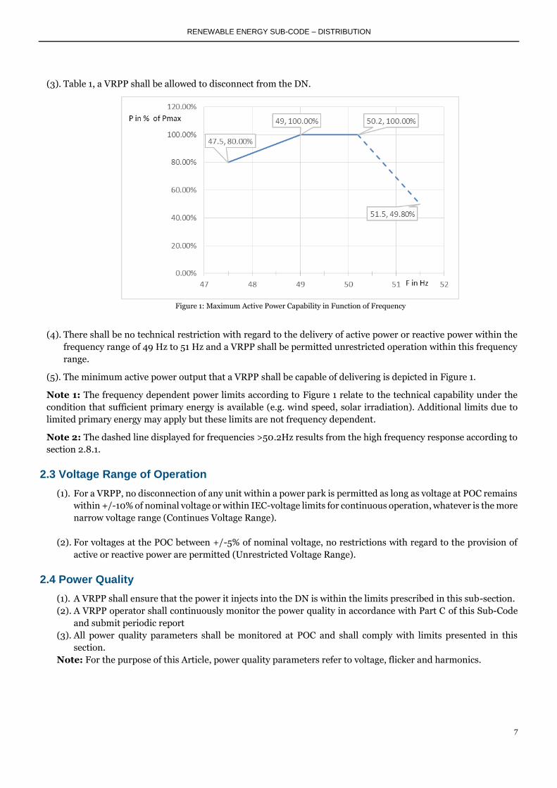
(3). Table 1, a VRPP shall be allowed to disconnect from the DN.
Figure 1: Maximum Active Power Capability in Function of Frequency
(4). There shall be no technical restriction with regard to the delivery of active power or reactive power within the
frequency range of 49 Hz to 51 Hz and a VRPP shall be permitted unrestricted operation within this frequency
range.
(5). The minimum active power output that a VRPP shall be capable of delivering is depicted in Figure 1.
Note 1: The frequency dependent power limits according to Figure 1 relate to the technical capability under the
condition that sufficient primary energy is available (e.g. wind speed, solar irradiation). Additional limits due to
limited primary energy may apply but these limits are not frequency dependent.
Note 2: The dashed line displayed for frequencies >50.2Hz results from the high frequency response according to
section 2.8.1.
2.3 Voltage Range of Operation
(1). For a VRPP, no disconnection of any unit within a power park is permitted as long as voltage at POC remains
within +/-10% of nominal voltage or within IEC-voltage limits for continuous operation, whatever is the more
narrow voltage range (Continues Voltage Range).
(2). For voltages at the POC between +/-5% of nominal voltage, no restrictions with regard to the provision of
active or reactive power are permitted (Unrestricted Voltage Range).
2.4 Power Quality
(1). A VRPP shall ensure that the power it injects into the DN is within the limits prescribed in this sub-section.
(2). A VRPP operator shall continuously monitor the power quality in accordance with Part C of this Sub-Code
and submit periodic report
(3). All power quality parameters shall be monitored at POC and shall comply with limits presented in this
section.
Note: For the purpose of this Article, power quality parameters refer to voltage, flicker and harmonics.

RENEWABLE ENERGY SUB-CODE – DISTRIBUTION
8
2.4.1 Rapid Voltage Changes
(1). During regular switching operations within a VRPP such as switching operation on a wind turbine within a
wind farm or switching of a shunt reactor or capacitor, the resulting voltage change at the POC shall not
deviate by more than 2 % of the Nominal Voltage.
(2). The maximum permitted voltage change at any point in the network shall be limited to 5 % of Nominal
Voltage in respect of changes resulting from;
a. switching of several units within a VRPP,
b. connection of a complete VRPP, or
c. disconnection of a complete VRPP.
2.4.2 Flicker
(1). A DU shall apportion flicker emission limits to each VRPP based on flicker planning levels according to
IEC61000-3-7, existing background flicker levels, possible future installations and the total size of a VRPP to
be connected. The methodology for apportioning VRPP-specific flicker limits shall be in-line with IEC61000-
3-7.
(2). In the absence of any project-specific flicker limits apportioned by the DU, flicker caused by any VRPP shall
not exceed the flicker limits as shown in Table 2 at POC.
Table 2: Flicker limits to be applied in the absence of apportioned limits
Planning level Emission Limit (MV)
Pst 0.4
Plt 0.4
2.4.3 Voltage Unbalance
(1). A VRPP’s contribution to negative sequence voltage shall not exceed 1 % at the POC.
Note: Voltage unbalance is measured in terms of negative sequence voltage in per cent of nominal voltage.
2.4.4 Harmonics
(1). A DU shall apportion individual harmonic voltage distortion limits to each VRPP based on planning level for
individual harmonic distortions (HD) and total harmonic distortion (THD) according to Article 19.70 of the
Distribution Code, existing background harmonics, possible future installations and the total size of a VRPP
to be connected, according to methodology described in IEC 61000-3.
(2). In the absence of any apportioned limits, individual harmonic voltage distortion limits for odd harmonics
shall not exceed 2 % and for even harmonics 1 %. Total harmonic voltage distortion shall not exceed 3 % at
the POC.
(3). In addition to (2), generators shall not exceed harmonic current distortion limits specified in Table 3 at the
POC.

RENEWABLE ENERGY SUB-CODE – DISTRIBUTION
9
Table 3: Current distortion limits for DN connected VRPPs
Current Harmonic Distortion limits
Isc/IL
Maximum Harmonic Current Distortion in Percent (%)of IL
Individual Harmonic Order "h" (Odd Harmonics)
<11 11≤h<17 17≤h<23 23≤h<35 35≤h TDD
<20* 4.0 2.0 1.5 0.6 0.3 5.0
20<50 7.0 3.5 2.5 1.0 0.5 8.0
50<100 10.0 4.5 4.0 1.5 0.7 12.0
100<1000 12.0 5.5 5.0 2.0 1.0 15.0
>1000 15.0 7.0 6.0 2.5 1.4 20.0
* All power generation equipment are limited to these values of current distortion, regardless of actual Isc/IL.
1. Even harmonics are limited to 25% of the odd harmonic limits above.
2. Current distortions that result in a dc offset, e.g. half-wave converters, are not allowed.
3. Isc = maximum short-circuit current at POC.
4. IL = maximum demand load current (fundamental frequency component of generation current) at POC.
5. TDD (Total Demand Distortion) = harmonic current distortion in % of maximum demand load (or
generation) current (15 or 30 min demand).
2.5 Reactive Power Capability
(1). A VRPP shall operate within a power factor range of 0.95 leading to 0.95 lagging, measured at the POC.
(2). For voltages between 0.9 and 1.0p.u., a VRPP shall provide maximum reactive power support to the system
or for voltages between 1.0 and 1.1p.u., a VRPP shall provide full bucking at the POC.
(3). A VRPP shall be capable of varying power factor continuously in the entire range of 0.95 under-excited to
0.95 over-excited during operation with maximum active power output and voltage within the Unrestricted
Range of Operation
(4). A VRPP shall be capable of varying reactive power at the POC within their reactive power capability range as
defined by Figure 3 when operating within the Unrestricted Voltage Range and at an active power output
level between 5% and 100% of Rated Power.
(5). If voltage is outside the Unrestricted Voltage Range but within the Continuous Voltage Range the reactive
power capability limits of a VRPP according to Figure 3 can be adjusted to the voltage dependent limits
according to Figure 2.
Note: Pn in MW corresponds to the rated installed capacity of the VRPP minus the sum of the installed
capacity of all units being temporarily out of service.
(6). In the case of operation with active power below 5% of Pn, there is no reactive power capability requirement
but in this range, reactive power must be within the tolerance range of +/-5% of Pn.

RENEWABLE ENERGY SUB-CODE – DISTRIBUTION
10
Figure 2: Reactive power requirements for DN connected VRPPs (corresponding to voltage)
Figure 3: Reactive power requirements for DN connected VRPPs at full and partial active power output conditions

RENEWABLE ENERGY SUB-CODE – DISTRIBUTION
11
2.6 Reactive Power Control Requirements
2.6.1 General
(1). A VRPP shall be equipped with control functions to control reactive power at the POC following instructions
from the DU using set-points and gradients and the parameter settings shall be agreed between the DU and
a VRPP operator shall be as documented in the relevant System Operational Manual.
(2). A VRPP shall support each of the following control functions:
a. Q control (details in 2.6.2)
b. Power Factor Control
(3). The choice of control mode and the definition of target values shall be within the responsibility of the DU
and it must be possible for the DU to change control mode and target values at any time during the lifetime
of a VRPP.
2.6.2 Reactive Power Control (Q Control)
(1). A VRPP shall be capable of controlling reactive power at the POC either to a constant reactive power target
(Q-target) or an active power dependent reactive power target (Q(P)).
(2). The DU shall define the actual settings of the Q/ Q(P) control characteristic (shape of Q(P)-characteristic,
target values).
(3). If the control target is changed by DU, such change shall be completed not later than 2 minutes after the
receipt of the new target value.
(4). The maximum permitted deviation of actual reactive power from the Q-target shall not be greater than 2%
of rated power, that is 0.02 p.u., 2 minutes after change of Q-target during steady system conditions.
Figure 4: Reactive power control function of DN connected VRPP (const Q-control and Q(P)-control)

RENEWABLE ENERGY SUB-CODE – DISTRIBUTION
12
2.6.3 Power Factor Control (Cosφ-Control)
(1). A VRPP shall be capable of controlling power factor at the POC either to a constant power factor target (cosφ
-target) or an active power dependent power factor target (cosφ (P)).
(2). The DU shall define the actual settings of the cosφ/cosφ(P) control characteristic (shape of cosφ (P)-
characteristic, cosφ -target).
(3). If the control target is changed by DU, such change shall be completed not later than 2 minutes after the
receipt of the new target value.
(4). The maximum permitted deviation of actual power factor from the cosφ -target shall be no greater than
cosφ =0.005, 2 minutes after change of cosφ -target during steady system conditions.
2.7 Active Power Control
(1). For system security reasons it may be necessary for the ETU or DU to curtail a VRPP’s active power output.
(2). A VRPP shall be capable of operating at a reduced power level if active power has been curtailed by ETU or
DU, for network or system security reasons;
(3). The accuracy of the control performed and of the set-point shall not deviate more than ±1 % of the rated
power.
(4). The type of communication between a DU and a VRPP operator must be agreed between the parties and
specified as part of the bilateral connection agreement.
(5). The relationship between the ETU and a VRPP shall be specified as part of the bilateral connection agreement
between the DU and a VRPP.
2.8 Frequency Response
2.8.1 High Frequency Response for VRPPs
(1). During high frequency operating conditions in NITS and DN, each DN connected VRPP shall be required to
operate at reduced active power output in order to stabilize grid frequency.
(2). When the frequency on the NITS and DN exceeds 50.2 Hz, each VRPP shall be required to reduce active
power as a function of change in frequency as illustrated in Figure 5.
(3). High frequency response must operate with a minimum gradient of 100% of rated power per minute as
provided by the primary frequency control time scales.

RENEWABLE ENERGY SUB-CODE – DISTRIBUTION
13
Figure 5: Mandatory high frequency response for all DN connected VRPPs
Note: ‘dP’ in the figure represents percentage of active power by which the output has to be decreased in case
of increasing system frequency.
2.8.2 Primary and Secondary Frequency Control
(1). Unless otherwise required by the ETU/DU, a VRPP shall be exempted from primary or secondary frequency
control capabilities except from high frequency response according to section 2.8.1.

RENEWABLE ENERGY SUB-CODE – DISTRIBUTION
14
2.9 Behaviour during Abnormal Voltage Conditions
2.9.1 Low Voltage Ride Through (LVRT) / High Voltage Ride Through (HVRT) Capability for VRPPs
(1). A VRPP shall be designed to operate for up to one minute within a voltage range of +/-15% of nominal voltage.
(2). A VRPP shall be designed to have LVRT and HVRT capability as illustrated in Figure 6.
(3). For all voltages at the POC, which are between the HVRT (red) and the LVRT (blue) lines according to Figure
6, no disconnection of a VRPP or of individual units within a VRPP shall be permitted.
(4). The voltage at POC is defined to be the lowest of the three line-line or line-earth voltages.
(5). If the voltage reverts to the Continuous Voltage Range (between Vcmin and Vcmax) during a fault sequence
resulting from reclosing, subsequent voltage drops or voltage spikes shall be regarded as new LVRT or HVRT
condition.
Figure 6: LVRT and HVRT capability for DN connected VRPPs
2.9.2 Reactive Current Support During LVRT/HVRT Situations
During a LVRT or HVRT situation, any VRPP having a direct connection to the secondary side of a substation shall
support the DN voltage by injecting (or absorbing) reactive current as follows:
(1). All units within a VRPP shall support the voltage by injecting or absorbing additional reactive current ΔIQ at
the generator terminals proportional to the change of the unit’s terminal voltage ΔVt, as depicted in Figure
7.
(2). The factor of proportionality between additional reactive current and voltage deviation is named K
(Iq=KVt and the factor K must be set within the range of 0≤K≤10.
(3). The absolute value I of current in each of the three phases of the unit’s terminals may be limited to rated
current (1 p.u.).

RENEWABLE ENERGY SUB-CODE – DISTRIBUTION
15
Notes:
1. Voltages and currents in this section are defined to be positive sequence components of fundamental
frequency value of voltages and currents respectively. This applies to pre-fault and post-fault voltages and
currents.
2. The additional reactive current IQ shall be injected in addition to the pre-fault voltage.
3. The positive sign of Iq in Figure 7 is voltage supporting injection of reactive power.
4. The voltage deviation Vt is defined by the difference between the pre-fault and the post-fault voltage.
5. The pre-fault current and pre-fault voltage are defined by the 1-minute average of current and voltage
respectively.
Figure 7: Reactive current support ΔIq during LVRT and HVRT situations at the unit’s terminals
(4). During dynamic performance, after 60ms the additional current must have settled, meaning that it shall
remain within a tolerance band of ±20% around the value according to Figure 7.
(5). During a LVRT situation, a VRPP having a connection on a distribution feeder shall control active and
reactive power according to a “zero current” strategy, meaning that both, active and reactive current shall be
reduced to zero.
(6). During a HVRT situation, a VRPP having a connection on a distribution feeder shall maintain normal active
and reactive power control modes.
2.9.3 Active and Reactive Power Behaviour During Voltage Recovery
(1). After voltage at POC has returned into the range of +/-15% of nominal voltage, a VRPP shall restore its active
power output to at least 90% of its pre-fault value within 1 second.
(2). During voltage recovery, a VRPP shall not absorb more reactive power than prior to the LVRT situation.

RENEWABLE ENERGY SUB-CODE – DISTRIBUTION
16
2.10 Automatic Resynchronisation
(1). Automatic synchronization device and automatic close equipment shall be installed by VRPP owner to
connect to the DN automatically, with a delay of 5 minutes, if the following system conditions are fulfilled:
a. Voltage at the POC is within the Steady State Range of +/-10% of nominal voltage, as specified
in the National Electricity Grid Code
b. Frequency is within the range of 49.8 Hz ≤ F ≤ 50.2 Hz.
(2). During automatic connection and synchronisation, a VRPP shall ensure compliance with “rapid voltage
change” requirements according to section 2.4.1.
2.11 Protection and Fault Levels
(1). A VRPP operator shall design, implement, coordinate and maintain its protection system to ensure the
desired speed, sensitivity and selectivity in clearing faults on VRPP’s side of the connection point (POC).
(2). Protection functions required for protecting the NITS or DN from getting out of normal operating ranges
shall be specified by the DU in consultation with the ETU, including trip-settings and response times.
(3). A VRPP shall be equipped with effective detection of islanded operation in all system configurations and shall
have the capability to shut down generation of power in such condition within 2 seconds.
(4). Operation in island with part of the DN shall not be permitted unless specifically agreed with the ETU and
DU.
(5). The coordination among protections at connection point shall be agreed between ETU, DU, and a VRPP
operator.
(6). The circuit breaker used for connection switching in the DN connected generators shall be equipped with a
disconnection system to ensure safe operation during re-connection and re-synchronization to the DN.
(7). The DU may request that the set values for protection functions be changed following commissioning if it is
deemed to be of importance to the operation of the NITS and DN except that, such a change shall not result
in a VRPP being exposed to negative impacts from the DN lying outside of the design requirements.
(8). The DU shall inform a VRPP operator of the highest and lowest short-circuit current that shall be expected
at the POC as well as any other information about the DN as may be necessary to define the VRPP's protection
functions.
(9). Where a VRPP’s protection equipment is required to communicate with the DU’s protection equipment it
must meet the communications interface requirements specified by the DU and this Sub-Code.
2.12 Communication and Control
(1). A VRPP shall be equipped to receive target values for control purposes from the ETU such as voltage/reactive
power control according to section 2.6, active power curtailment according to 2.7 and other control functions
as it may be applicable.
(2). All further requirements with regard to the exchange of information shall be agreed on between a VRPP
operator and DU within the bilateral connection agreement.

RENEWABLE ENERGY SUB-CODE – DISTRIBUTION
17
PART C:
3 Testing, Inspection and Compliance Monitoring (1). A VRPP operator shall demonstrate compliance to all applicable requirements specified in this Sub-Code and
any other applicable code or standard approved by DU in consultation with ETU, as applicable, before being
allowed to connect to the DS and operate commercially.
(2). A VRPP operator shall review and confirm to the DU, compliance by the VRPP with every requirement of
this Sub-Code and shall do so according to article 19.65 of the National Electricity Distribution Code.
(3). A VRPP operator shall conduct tests or studies to demonstrate that the VRPP complies with each of the
requirements of this Sub-Code and submit such test reports to the DU.
(4). A VRPP operator shall continuously monitor its compliance in all material respects with all the connection
conditions of this Sub-Code.
(5). The DU may issue an instruction requiring a VRPP operator to carry out a test to demonstrate that the VRPP
complies with this Sub-Code’s requirements and a VRPP operator shall not refuse such an instruction.
(6). A VRPP operator shall keep records relating to the compliance of the VRPP with each section of this Sub-
Code, or any other code applicable to that VRPP, setting out such information that the DU reasonably
requires for assessing power system performance, including the actual VRPP performance during abnormal
or continuous operating conditions.
(7). Records generated under Part C of this Sub-Code shall be kept for a minimum of 5 years unless otherwise
specified in this Sub-Code commencing from the date the information was generated.


