Replacing the Upper Ball Joint & Upper Control Arm on a 2007 Honda Accord 4CYL Disclaimer: I have benefited greatly from others who have taken the time to post auto repair videos/tutorials online. To try and return the favor, I have documented a few of my recent repairs. I try to perform the work conscientiously in accordance with the Honda service manual, but I am not a professional technician by any stretch. I do hope this information might benefit others who are preparing to do this job. Typical symptoms of a bad upper ball joint include a “clunking” noise when driving over bumps and a poor tire wear pattern. The upper ball joint can be checked by grabbing the wheel at the 12:00 and 6:00 positions (as shown below) and shaking to check for play. To check if the play is in the upper ball joint, remove the wheel and grab the upper part of the knuckle as shown below. If you shake it back and forth as shown, you should not see any movement in the upper ball joint. If you see/feel any movement in the ball joint, it is likely that the ball joint is bad. In my case, I could see a small but definite movement in the joint.
Transcript
Replacing the Upper Ball Joint & Upper Control Arm on a 2007 Honda Accord 4CYL
Disclaimer: I have benefited greatly from others who have taken the time to post auto repair
videos/tutorials online. To try and return the favor, I have documented a few of my recent repairs. I try to
perform the work conscientiously in accordance with the Honda service manual, but I am not a
professional technician by any stretch. I do hope this information might benefit others who are preparing
to do this job.
Typical symptoms of a bad upper ball joint include a “clunking” noise when driving over bumps and a poor tire wear pattern. The upper ball joint can be checked by grabbing the wheel at the 12:00 and 6:00 positions (as shown below) and shaking to check for play.
To check if the play is in the upper ball joint, remove the wheel and grab the upper part of the knuckle as shown below. If you shake it back and forth as shown, you should not see any movement in the upper ball joint. If you see/feel any movement in the ball joint, it is likely that the ball joint is bad. In my case, I could see a small but definite movement in the joint.
The figure below shows the front suspension components. The upper ball joint is not available separately
from the upper control arm (at least not from Honda) so the entire upper control arm needs to be
replaced (around $60 for the OEM part online).
Upper Ball
Joint
Upper
Control Arm Knuckle
Fork
Lower
Control Arm
Strut/Damper
#1 ‐ Support vehicle on jack stands and remove the wheel.
#2 ‐ Apply your favorite penetrating oil (PB Blaster, Liquid Wrench, WD40 Penetrating Oil, Kroil) to the
nut on the bolt connecting the strut fork to the lower control arm.
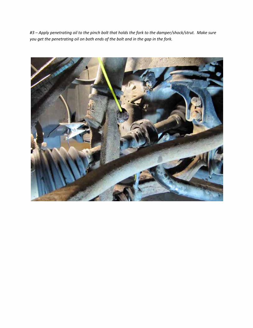
#3 – Apply penetrating oil to the pinch bolt that holds the fork to the damper/shock/strut. Make sure
you get the penetrating oil on both ends of the bolt and in the gap in the fork.
#4 – Remove the pinch bolt holding the strut to the fork.
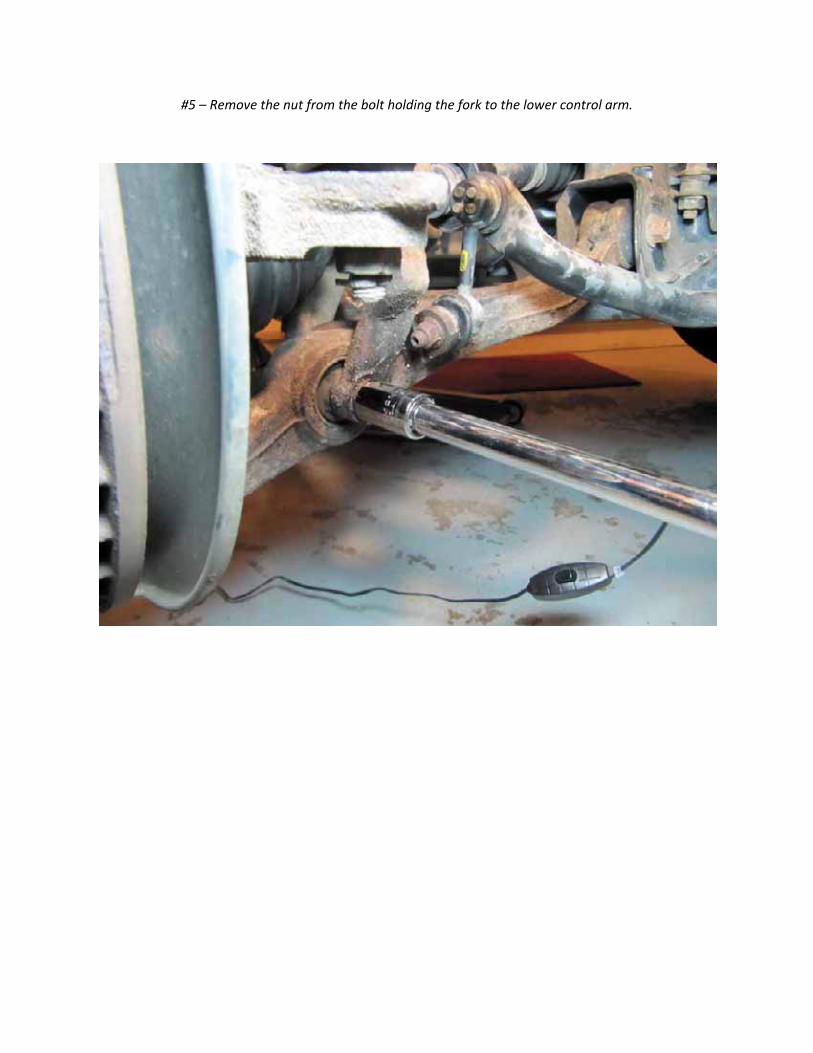
#5 – Remove the nut from the bolt holding the fork to the lower control arm.
#6 – It may be necessary to hold the bolt head on the other side to prevent it from turning when
loosening the nut.
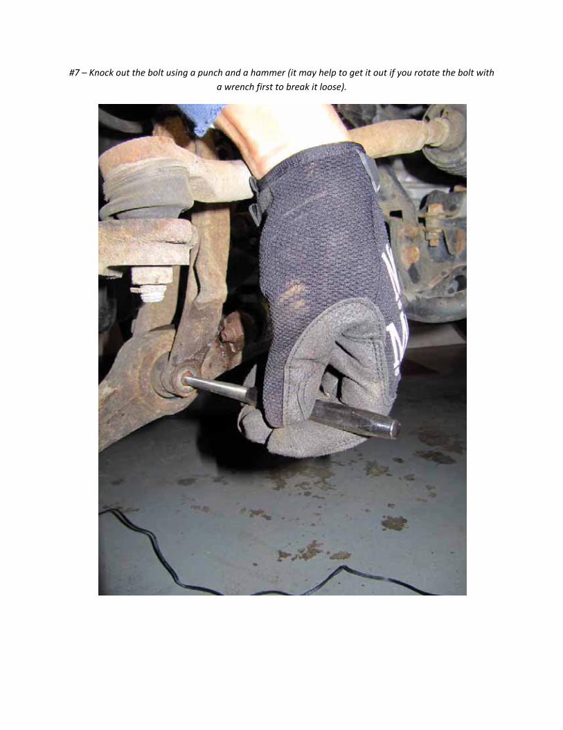
#7 – Knock out the bolt using a punch and a hammer (it may help to get it out if you rotate the bolt with
a wrench first to break it loose).
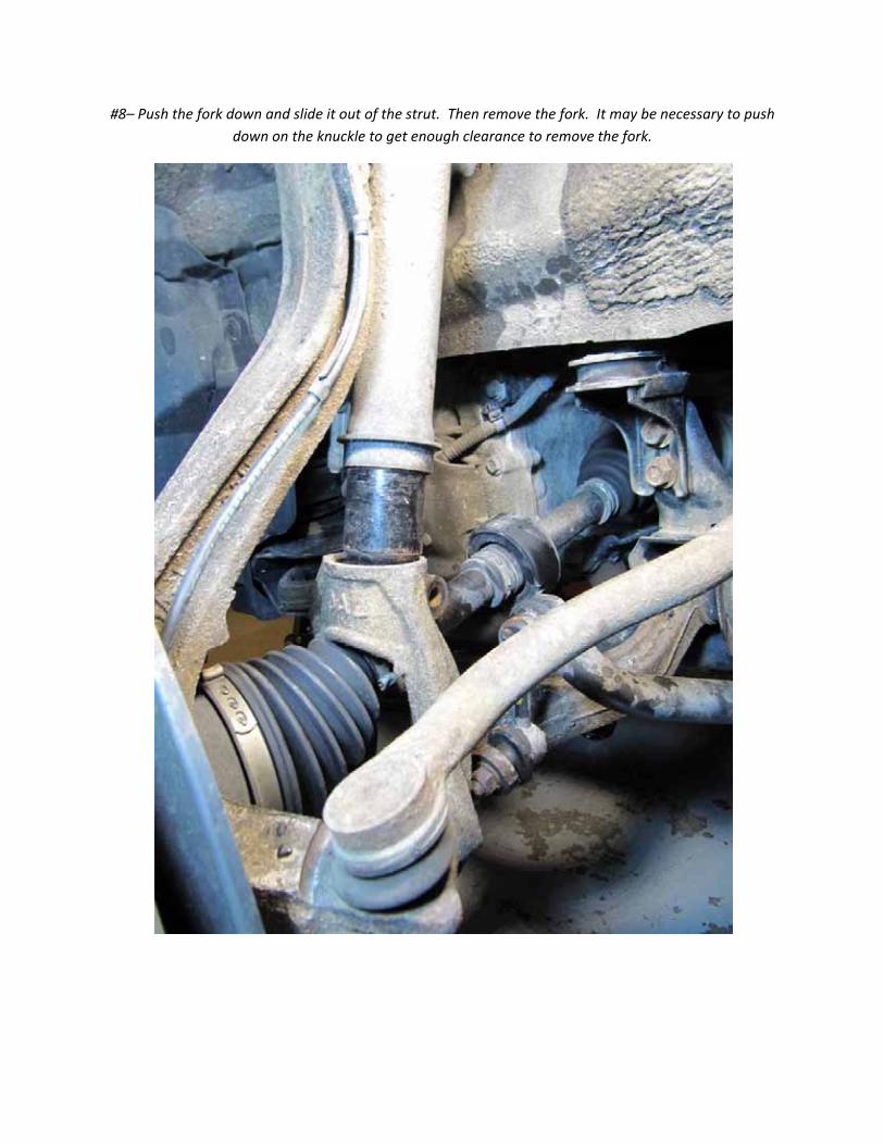
#8– Push the fork down and slide it out of the strut. Then remove the fork. It may be necessary to push
down on the knuckle to get enough clearance to remove the fork.
#9 – Remove the 5 bolts shown below which hold the strut assembly to the chassis. Don’t touch the one
in the center (which holds the strut assembly together) or you will have a bad day.
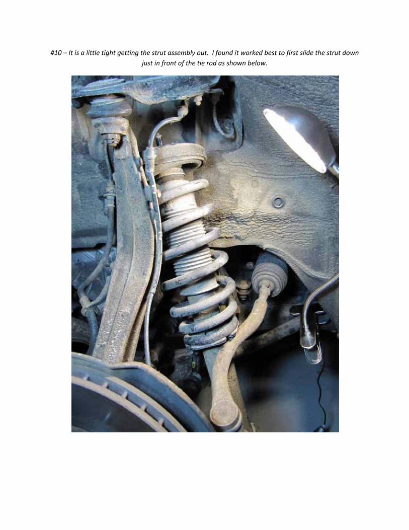
#10 – It is a little tight getting the strut assembly out. I found it worked best to first slide the strut down
just in front of the tie rod as shown below.
#11 – Then the top of the strut can be pulled out from under the knuckle and the whole strut can be
removed.
#12 – Remove the ABS sensor line bracket from the upper control arm by removing the nut shown below.
#13 – Unbend the ends of the cotter pin from the castle nut on the upper ball joint and pull out the cotter
pin.
#14 – Loosen the Castle nut (red arrow) as shown, but don’t remove it completely yet as it will keep the
knuckle from flying around when the ball joint is removed from the knuckle.
#15 – Connect a ball joint separator tool as shown below to push the ball joint tapered pin from the
knuckle. (Some folks recommend rapping the outside of the knuckle with a hammer to free the ball joint.
The Honda service manual specifically recommends not doing this. A ball joint tool like the one shown is
available for about $20. In this case, since the upper ball joint is going to be replaced anyway, maybe the
hammer technique is acceptable, but I had the tool and went that route.)
#16 – Side view showing placement of the ball joint separator.
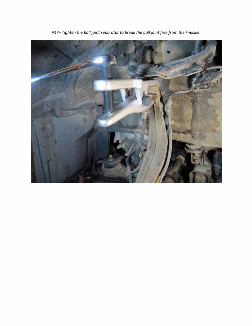
#17– Tighten the ball joint separator to break the ball joint free from the knuckle.
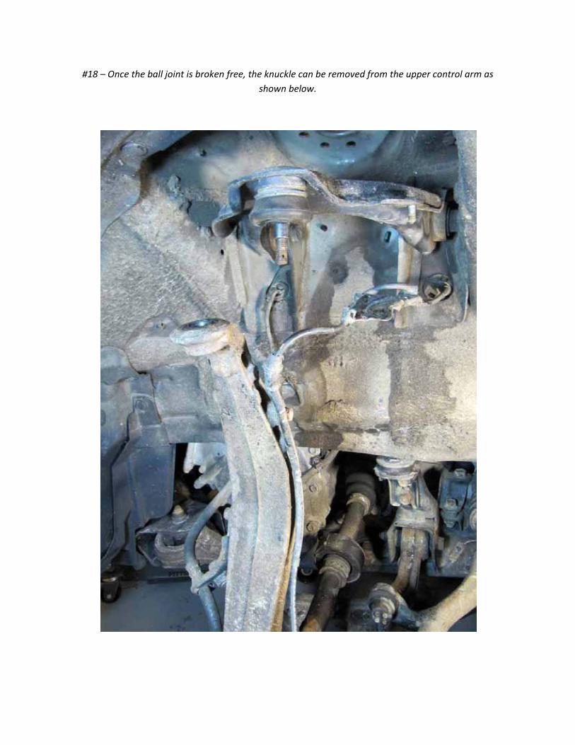
#18 – Once the ball joint is broken free, the knuckle can be removed from the upper control arm as
shown below.
#19 – Remove the two bolts holding the upper control arm to the chassis.
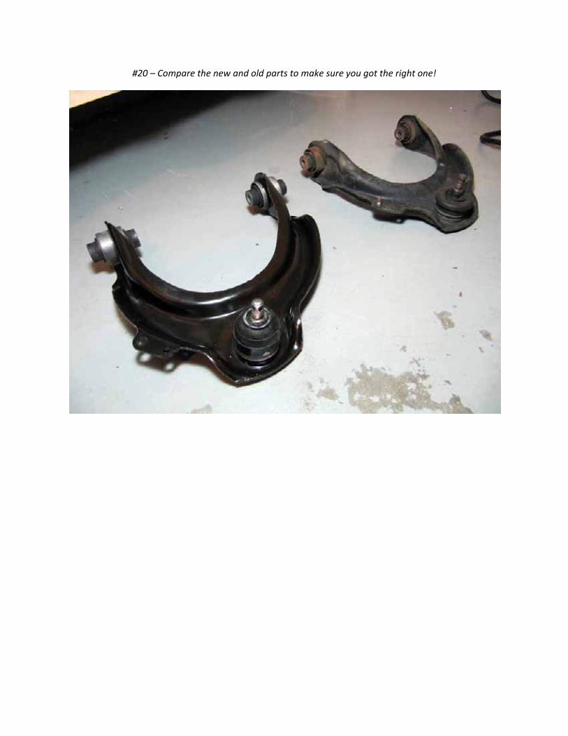
#20 – Compare the new and old parts to make sure you got the right one!
#21 – My new upper control arm didn’t come with the bolt for the ABS wire bracket installed (red arrow),
so I had to remove the bolt from the old upper control arm.
#22 – I just banged it out with a hammer.
#23 – And put it in the new control arm fastening down the bolt temporarily to press the bolt into the
arm.
#24 – Clean off the knuckle’s mating surfaces to the ball joint to ensure that the ball joint tapered pin
and boot will make a good seal. I used brake cleaner, a rag, and a scraper to clean off the top of the
knuckle.
#25 – To install the new upper control arm you need a thin metal rod about 12 inches long. I used a
piece of 3/16” diameter steel rod from Lowes that I cut to a 12 inch length.
#26 – Insert the new control arm and put in the bolts to hold it loosely in place. Before tightening the
bolts, insert the rod (red arrow) into the holes in the chassis (green arrows). This places the upper
control arm in its nominal position so the bushings are not under rotational stress when the suspension is
in its nominal position.
#27– With the rod holding the upper control arm at the correct angle, torque down both of the bolts to
their final torque spec.
#28– Push down the upper control arm and insert the ball joint pin into the knuckle. Loosely install the
castle nut (arrow) but do not tighten it yet.
#29 – Insert the strut into place.
#30 – Loosely install the nuts to hold the strut in place, but do not tighten yet.
#31 – Insert the fork over the axle and insert the bottom of the strut into the fork.
#32– The strut/damper must be correctly oriented when mating with the fork so that the pinch bolt lines
up with the groove in the damper. Specifically the alignment marker (red arrow) on the strut must line
up and insert into the pinch gap in the fork (green arrow).
#33 – Here is a zoomed in view showing what it looks like when the strut is fully inserted into the fork.
#33 – It may be necessary to push down on the rotor/knuckle in order to get enough room to attach the
fork onto the strut.
#34 – Insert the bolt to hold the fork to the lower control arm and attach a new nut. This is a locking nut
so a new nut should be used whenever it is removed. According to the Honda service manual, this bolt
should be replaced as well. Don’t tighten the nut down yet, just put it in place loosely.
#35 – Install the pinch bolt but do not tighten it down yet.
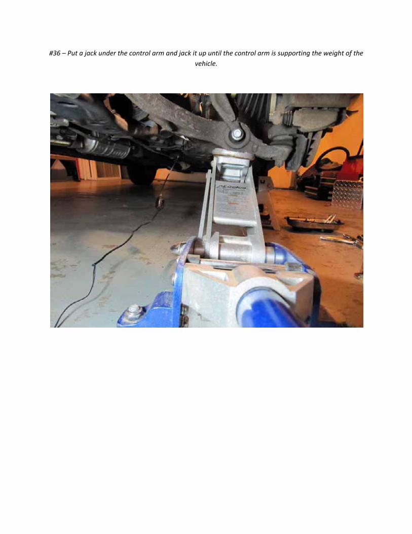
#36 – Put a jack under the control arm and jack it up until the control arm is supporting the weight of the
vehicle.
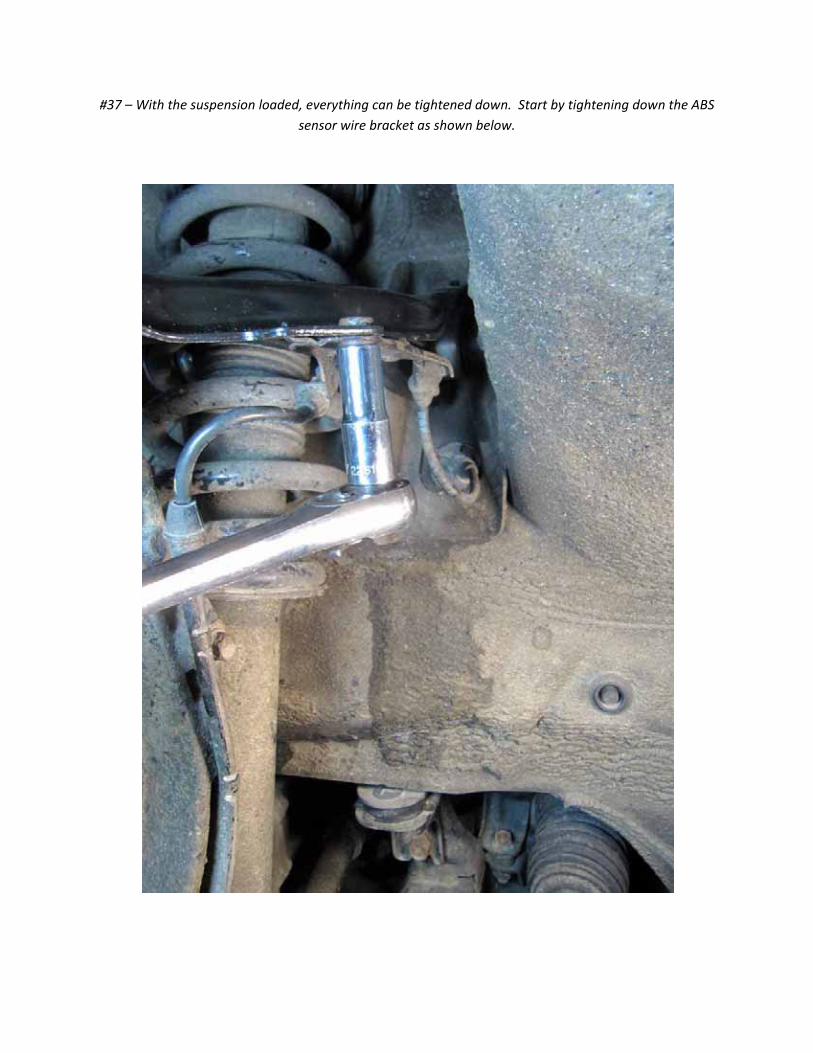
#37 – With the suspension loaded, everything can be tightened down. Start by tightening down the ABS
sensor wire bracket as shown below.
#38 – Torque the pinch bolt to its specified torque (32 lb‐ft).
#39 – Tighten the bolt holding the fork to the lower control arm to spec (47 lb‐ft).
#40 – Torque the ball joint castle nut to its MINIMUM torque specification (29 lb‐ft).
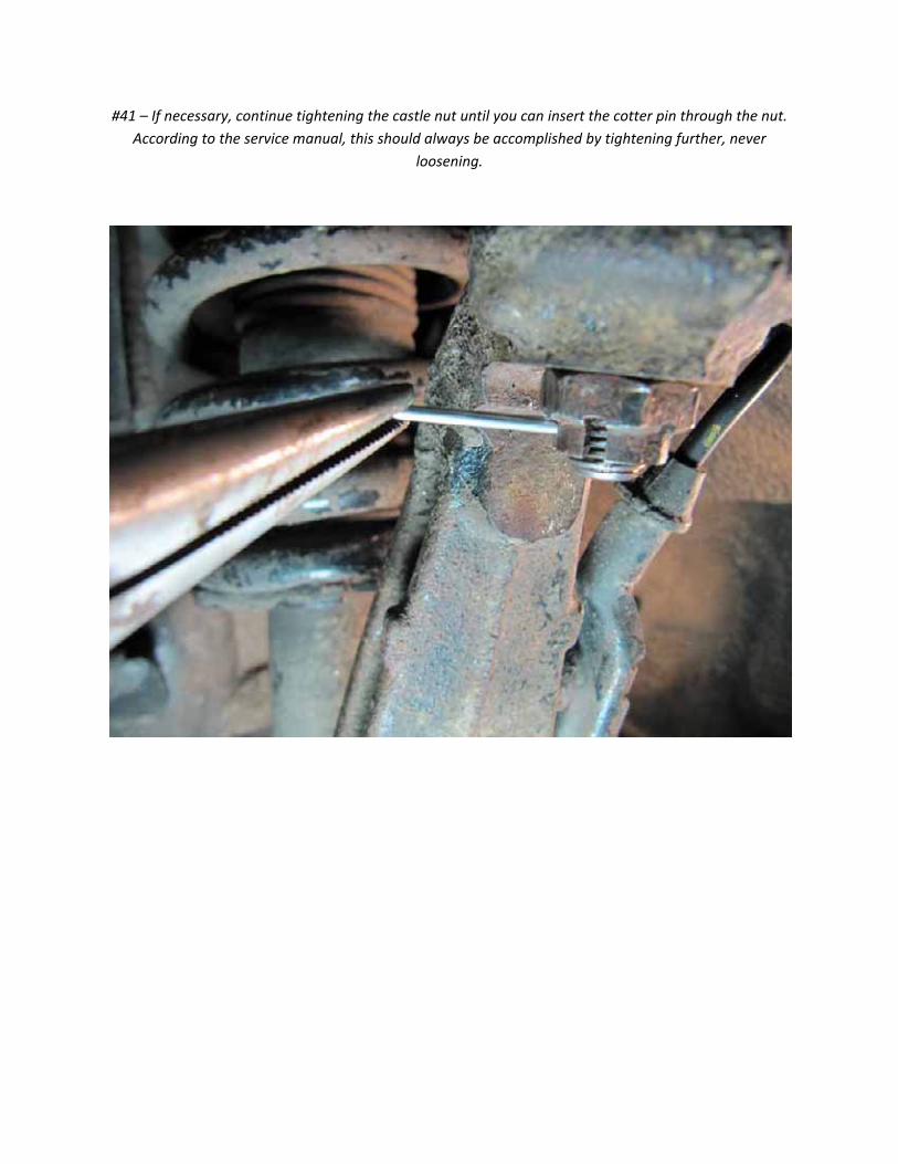
#41 – If necessary, continue tightening the castle nut until you can insert the cotter pin through the nut.
According to the service manual, this should always be accomplished by tightening further, never
loosening.
#42 – Bend over the ends of the cotter pin to hold it in place.
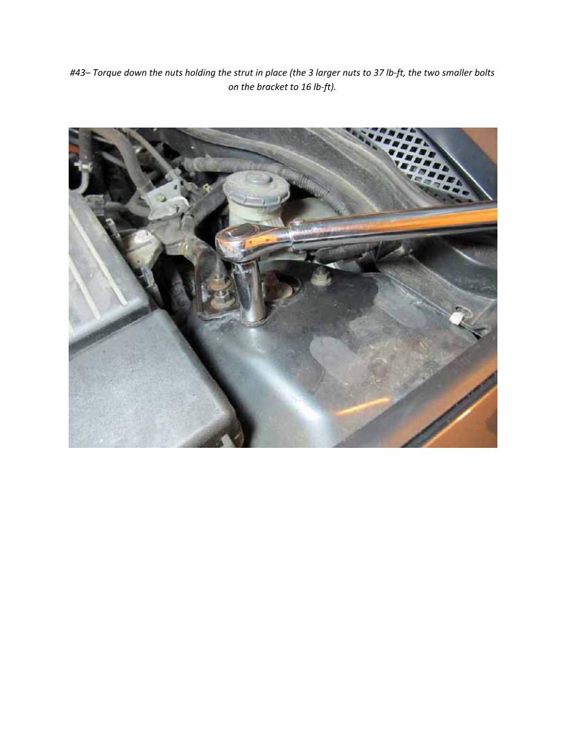
#43– Torque down the nuts holding the strut in place (the 3 larger nuts to 37 lb‐ft, the two smaller bolts
on the bracket to 16 lb‐ft).
#44 – In case you are curious, here is what it looks like inside the bad ball joint with the boot and grease
removed. There was a small amount of play which could be felt and the pin moved around much more
freely than the new one. Still looks like it would have been a while before my wheel fell off :)
Problems you might encounter:
1. The Pinch bolt gets VERY corroded in place and can be VERY difficult to remove. This is because the
pinch area and the open end allow moisture to enter and really freeze this bolt in place. You are
probably best off to use an impact wrench on this bolt. However, it is possible to shear the head off even
with an impact wrench – don’t ask me how I know this :). I would recommend soaking the pinch bolt in
penetrating oil. Be sure to spray the head, bolt bottom and in the pinch region of the fork (the gap that
gets pinched when the bolt is tightened). It will probably work best if you do this a few times over a
period of a few days to give the penetrating oil plenty of time to penetrate before trying to loosen it.