REPORT GEOTECHNICAL ENGINEERING INVESTIGATION Proposed Mixed-Use Building 2870 W. Olympic Blvd Los Angeles, California for David Lo 2867 W. Olympic Blvd Los Angeles, California 90006 Project No.: 1420-S September 16, 2016
Transcript
REPORT
GEOTECHNICAL ENGINEERING INVESTIGATION
Proposed Mixed-Use Building 2870 W. Olympic Blvd
Los Angeles, California
for
David Lo 2867 W. Olympic Blvd
Los Angeles, California 90006
Project No.: 1420-S September 16, 2016
PGI PACIFIC GEOTECH, INC. GEOTECHNICAL ENGINEERING CONSULTANT
15038 CLARK A VE, HACIENDA HEIGHTS, CA 91745 • TEL 626-333-8507 • FAX 626-333-5056
September 16, 2016 Project No.: 1420-S
David Lo 2867 W. Olympic Blvd Los Angeles, California 90006
SUBJECT:
Dear Mr. Lo,
Geotechnical Eng ineering Investigation Proposed Mixed-Use Building 2870 W. Olympic Blvd, Los Angeles, CA
In accordance with our proposal dated December 14, 2015, a Geotechnical Engineering Investigation has been conducted for the above-referenced project. The accompanying report presents the findings of our study, and our conclusions and recommendations pertaining to the geotechnical aspects of construction. Based on the results of our investigation, it is our opin ion that the site can be developed as proposed, provided the recommendations of this report are fo llowed and implemented during design and construction.
We appreciate the opportunity to be of service on this project. If you have questions regarding the content of this report of if we may be of additional assistance, please do not hesitate to call at any time .
Sincerely,
Paul S. Kim, PE, G RGE No. 2066
Table of Contents
1. PURPOSE AND SCOPE ....................................... ................................................................ - 1 -
VICINITY MAP SITE PLAN & BORING LOCATION CROSS SECTION LATERAL EARTH PRESSURE ANALYSIS FOR RETAINING WALL STABILITY ANALYSIS FOR VERTICAL OPEN CUT LATERAL EARTH PRESSURE DIAGRAM FOR SHORING LATERAL EARTH PRESSURE ANALYSIS FOR SHORING WALL
LOG OF TEST BORING LABORATORY TEST
Project No.: 1420-S Page - 1 -2870 W . Olympic Blvd, Los Angeles
1. PURPOSE AND SCOPE
This report presents the results of a geotechnical investigation for a proposed mixed-use building
to be constructed at the subject site. The location of the site relative to surrounding streets and
landmarks is shown on the Vicinity Map, Plate 1. The purpose of the investigation is to evaluate
subsurface soil conditions and, based on the conditions encountered, to provide conclusion and
recommendations pertaining to the geotechnical aspects of design and construction .
The scope of services authorized for this project includes a visual site reconnaissance, subsurface
exploration , field and laboratory testing , and geotechnical engineering analyses to provide criteria
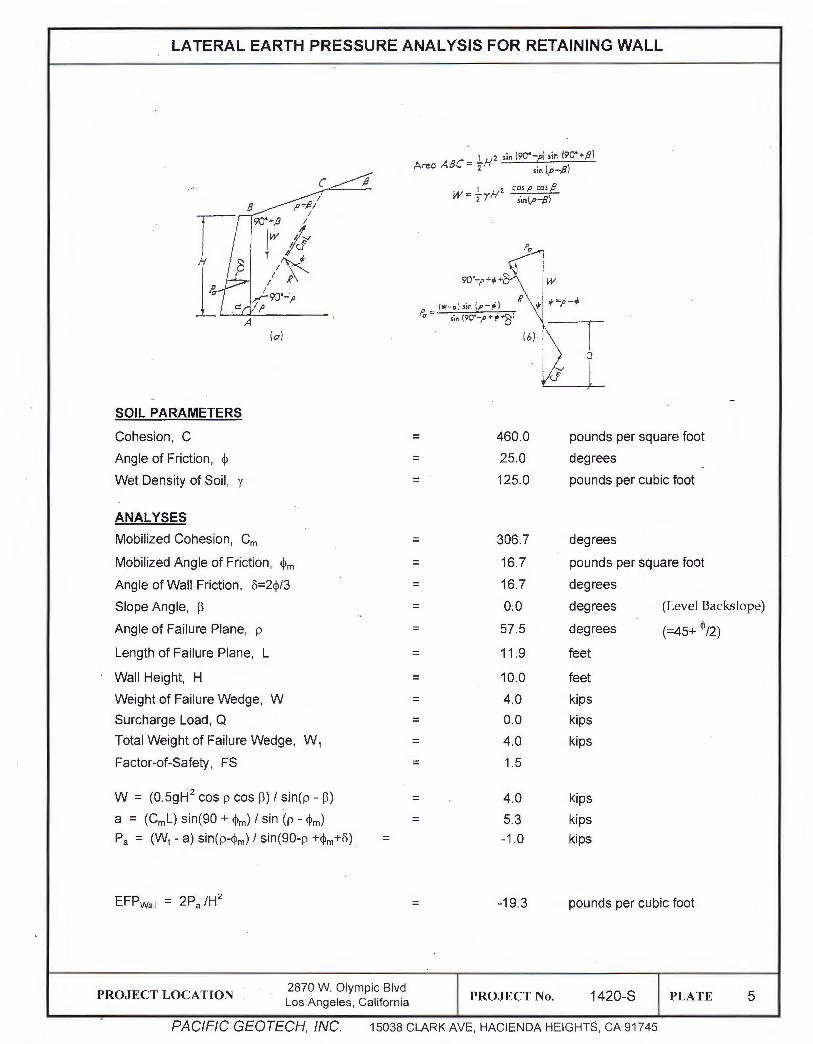
for preparing design of the building foundation, floor slab, basement/retaining walls, and shoring.
Recommendations presented in this report are based on the architectural plans provided by the
client. The design information shall be reviewed with actual building details and site plan details.
We should be notified of discrepancies to evaluate the impact upon the geotechnical
recommendations.
This report has been prepared for use in design of the described project. It may not contain
sufficient information for other purposes. Our professional services have been performed in
accordance with generally accepted engineering procedures under similar circumstances . No
other warranty, expressed or implied, is made as to the professional advice included in this report.
2. PROJECT DESCRIPTION
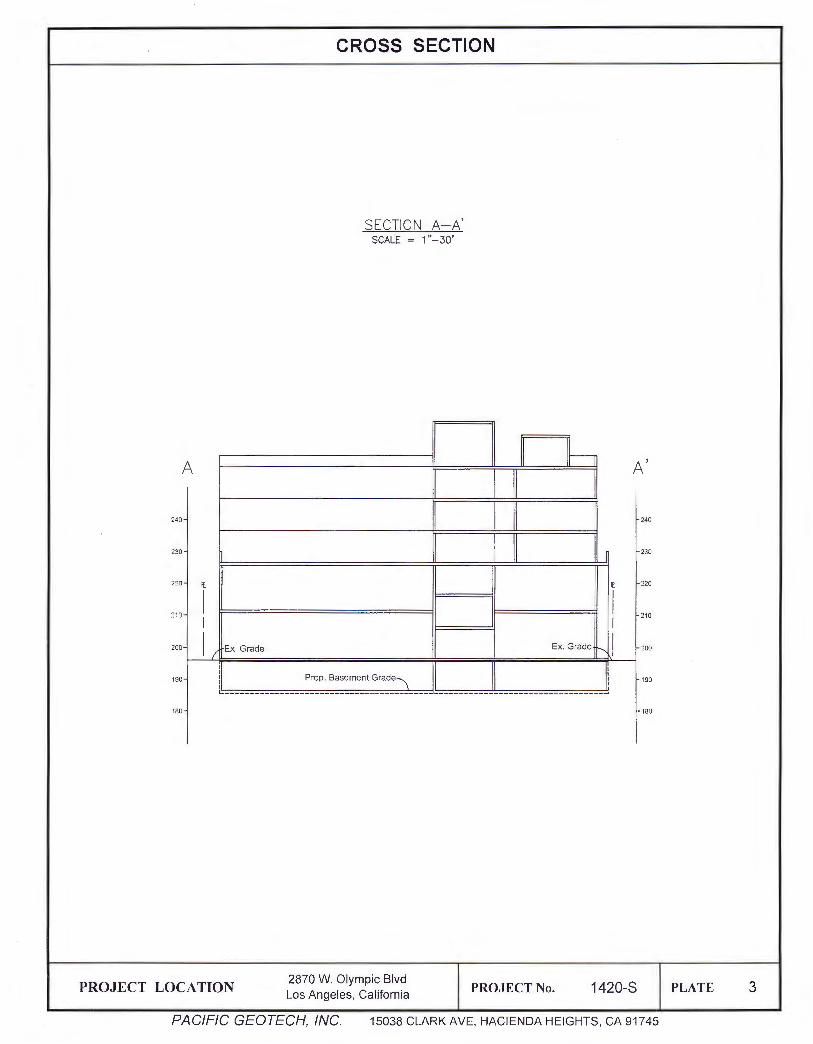
The proposed project is to construct a five-story mixed use building over one level of subterranean
parking garage as shown on the Site Plan and Boring Location on Plate 2.
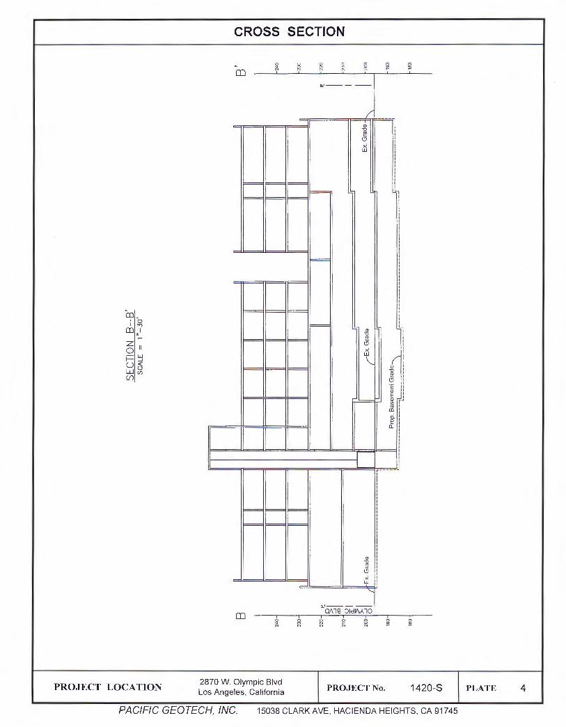
The subterranean garage floor will be 10 feet below grade. Cross sections depicting the existing
and proposed garage grades are shown on Plates 3 and 4.
PACIFIC GEOTECH, INC.
Project No.: 1420-S Page - 2 -2870 W. Olympic Blvd, Los Angeles
3. SITE DESCRIPTION
The subject property is located on the southeast corner of Olympic Blvd and Kenmore Ave in the
Korea Town area of the city of Los Angeles. The lot is rectangular in shape that measures 128' wide
along Olympic Blvd and 236' deep along Kenmore Ave. The site is bounded on the north by Olympic
Blvd , the west by Kenmore Ave, and on the other two sides by developed lots with existing apartment
buildings.
The site is flat and being used for commercial buildings, single family house and parking lot.
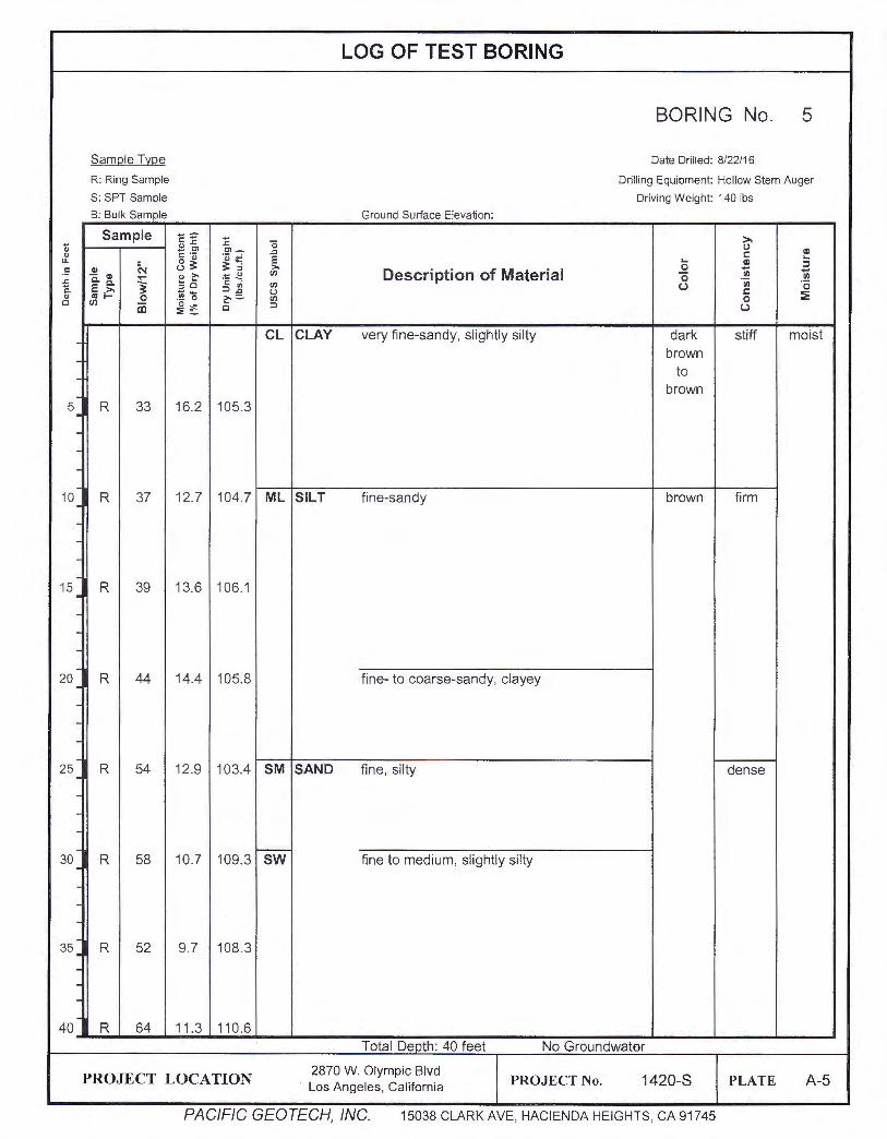
4. SUBSURFACE EXPLORATION
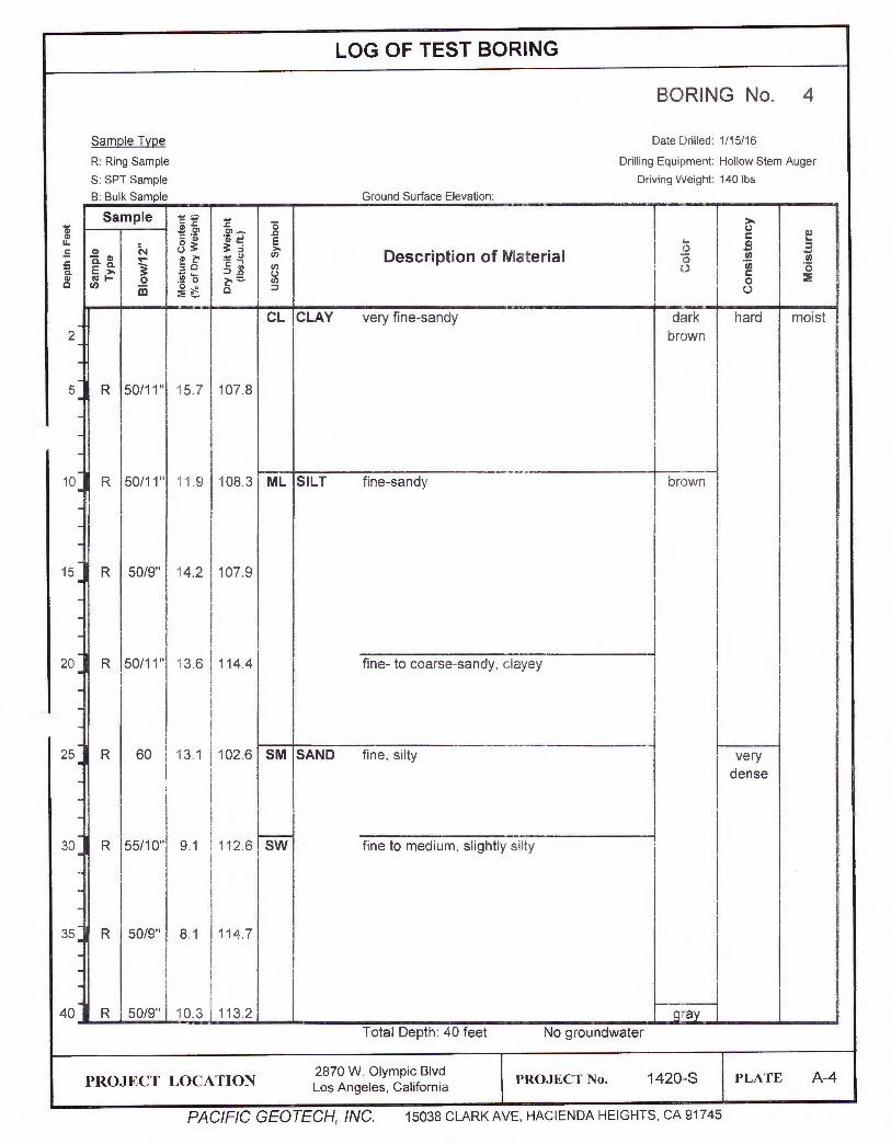
Field exploration for the subject site consisted of five test borings drilled to depths of 40 to 50 feet
below existing grade by means of a hollow stem auger. The approximate test boring locations are
indicated on the Site Plan and Boring Location on Plate 2. The explorations were logged by our
field engineer and relatively undisturbed samples were obtained for laboratory testing and
inspection. Logs of the test borings are presented in APPENDIX A.
5. SUBSURFACE CONDITIONS
5.1 Soil Conditions
The subsurface soils consist generally of alternating layers of stiff to hard, sandy CLAY, firm to
hard, sandy and clayey SILT, and very dense, silty to clayey SAND to the depth explored of 50
feet.
5.2 Groundwater
Groundwater was encountered in Boring-4 at the depth of 40 feet below existing grade.
6. LABORATORY TESTING
Laboratory testing was programmed following a review of the field investigation, and after
considering the probable foundation system to be evaluated. Selected soil samples were tested
for the following properties:
PACIFIC GEOTECH, INC.
Project No.: 1420-S Page - 3 -2870 W . Olympic Blvd, Los Angeles
• Field Moisture and Unit Weight (ASTM D-2216)
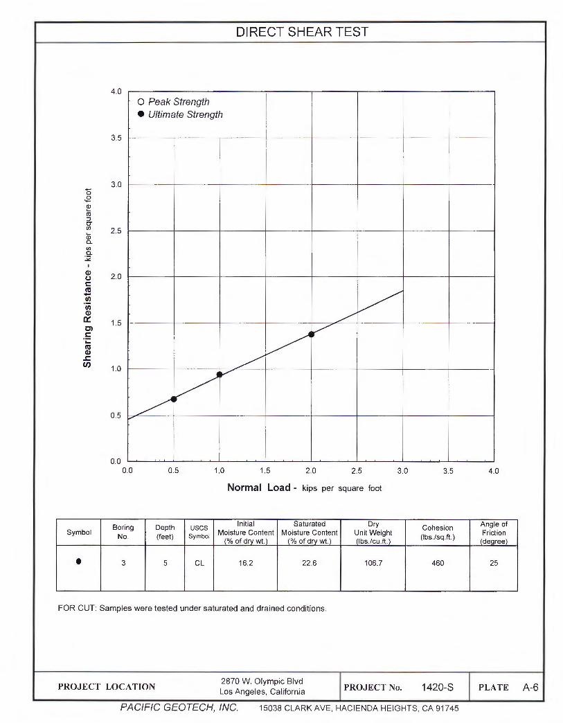
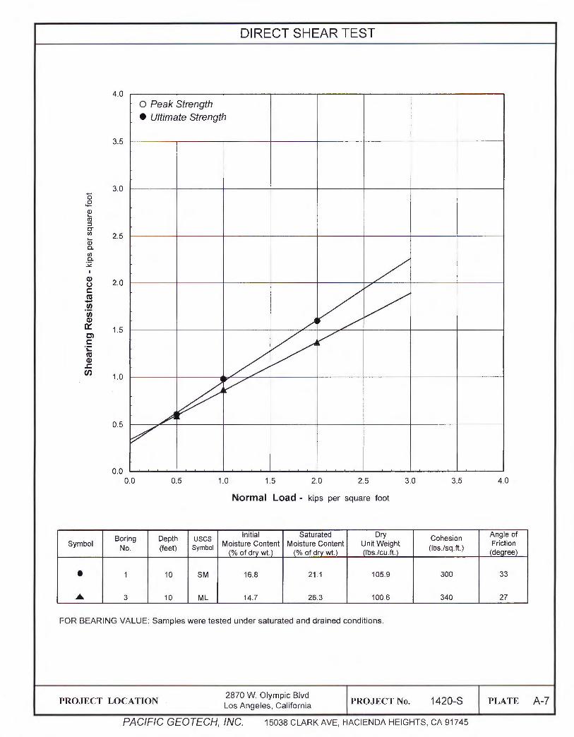
• Shear Resistance (ASTM D-3080)
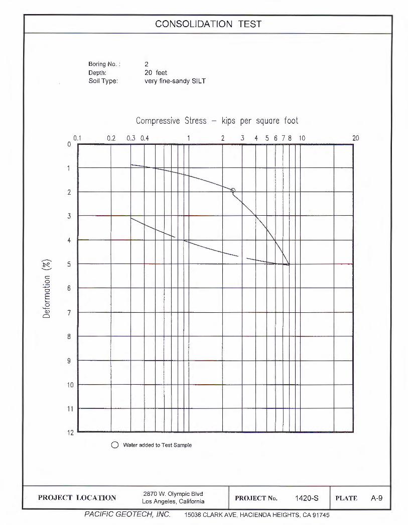
• Consolidation Characteristics (ASTM D-2435)
• Expansion Index (ASTM D-4829)
The test results of moisture content and unit weight are tabulated in the Log of Boring and
shearing resistance and consolidation characteristics are plotted on Direct Shear and
Consolidation, respectively, in APPENDIX A.
Expansion Test
An expansion test was performed on a representative sample of the onsite clay material in
accordance with ASTM D-4829 to evaluate its volume change with moisture. The test result is as
follows:
Sample Classification
B-1 @ 5' CLAY, coarse-sandy, dark brown
7. EARTHQUAKE HAZARDS
7.1 Faulting
Expansion Index
93
Expansion Potential
High
Based on criteria established by the California Geological Survey, faults may be categorized as
active, potentially active, or inactive. Active faults are those that show evidence of surface
displacement within the last 11 ,000 years. Potentially active faults are those that show evidence of
last displacement within the last 1.6 million years. Faults showing no evidence of displacement
within the last 1.6 million years may be considered inactive for most purposes, except for some
critical structures.
In 1972, the Alquist-Priolo Earthquake Fault Zoning Act was enacted. The act defines active and
potentially active faults essentially the same way as that used by the California Geological Survey.
The site is not located within a designated Alquist-Priolo Earthquake Fault Zone. No active or
potentially active faults are known to exist within the site . The probability of surface rupture at the
site is considered to be very low.
PACIFIC GEOTECH, INC.
Project No.: 1420-S Page - 4 -2870 W. Olympic Blvd , Los Angeles
According to the "Maps of Known Active Fault Near Source zones in California and Adjacent
Portions of Nevada" (Feb. 1998), the site is located within 2 km of a known active fault, which is
the Puente Hills Blind Trust Fault. The proposed structure shall be designed in accordance with
the Earthquake Regulations of the 2014 City of Los Angeles Building Code and the seismic design
parameters provided in this report.
7 .2 Liquefaction Potential
Based on the State of California "Seismic Hazard Zones" map, the site is not in an area where
historic occurrences of liquefaction, or local geologic, geotechnical or groundwater conditions
indicate a potential for liquefaction.
8. CONCLUSION AND RECOMMENDATIONS
Based on our evaluation of the site conditions and findings of this investigation, it is concluded that
the development of the subject property is feasible for the intended use from a geotechnical
engineering viewpoint provided the following conclusions and recommendations are incorporated
into design criteria and project specifications and are implemented during construction.
The proposed building may be supported on conventional spread footings founded in the existing
native soil at the proposed basement garage floor level.
8.1 Soil Expansion
An expansion index test was performed on a sample of the clay material in accordance with the
ASTM D-4829 to evaluate its volume change with moisture. The test result indicates that the
clayey sand has high expansion potential with an El of 93.
8.2 Seismic Design Parameters
Based on the 2014 City of Los Angeles Building Code and site soil properties, the site is classified
as Site Class D and the following seismic design parameters are applicable:
PACIFIC GEOTECH, INC.
Project No. : 1420-S Page - 5 -2870 W. Olympic Blvd, Los Angeles
SEISMIC COEFFICIENTS (2014 City of Los Angeles Building Code)
Nature of Occupancy II (Table 1604.5, CBC 2013)
Importance Factors 1.0 (Table 1.5-2 ASCE 7-10)
Short Period (0.2s) One-Second Period
Earth Materials and Site Class Alluvium - So (Table 20.3-1 ASCE 7-10)
Mapped Maximum Considered Earthquake (MCE) Spectral Response Acceleration Ss = 2.275 (g) S1 = 0.802 (g) (Figures 1613.3.1 (1) through 1613.3.1 (6))
Site Coefficients Fa= 1.0 Fv = 1.5 (Table 1613A.3.3(1) and 1613A.3.3(2))
~l):~'.i . of material is Well-graded sands or gravelly sands, LARGER thon CLEAN SANDS
SW lirtle or no fines. No. 200 sieve
?X~:i!. size) SANDS (Little or no fines) Poorly-graded sands or gravelly sands,
· (More than 50 % . SP little or no fines . . .. ·:.···· of coarse fraction .·.::.:·.-: is SMALLER thon 'f the No • .4 sieve SANDS .· .
SM Silty sands, sand-si It mixtures. sin) WITH FINES
~ (Appreciable amt. of fines) ~ ~. .
SC Clayey sands, sand-cloy mixtures.
Inorganic silts and very fine sands, rock Ml flour, silty or clayey line sands or clayey
silts with slight plasticity.
- Sil TS ANO CLAYS ~ Inorganic cloys of low to medium P.lasticity,.
FINE CL gravelly clays, sandy clays, silty clays, lean
<Liquid limit LESS than 50) ~ cloys.. GRAINED
SOILS OL Organic silts and organic silt-cloys of low plasticity.
<More than SO% of material is MH
Inorganic silts. micoceous or diotomoc·eous
SMALLER thon fine sondy or silty soils, elastic silts. No. 200 sieve
~~ ., size) SIL TS ANO CLAYS
~ CH Inorganic days of high plasticity, for clays. <Liquid limit GREATER thon SO>
~ OH Organic clays cf medium to high plasticity, or~onic si Its. --
HIGHLY ORGANIC SOILS ':zz::lZ.
Pt Peet end other highly organic: soils. 'ZIZZ 7TTT
BOUNDARY CLASSIFICATIONS: Soils Possessing characteristics of two groups are designated by ccmbinctions of group symbols.
Referen~e : The Unified Soil Clossification System, Corps of Enginee~. U.S. Army Technical Memorandum No. 3-357, Vol. l, March, 1953 !Revised April, 1960)
PROJECT LOCATION 2870 W. Olympic Blvd
PROJECT No. 1420-S PLATE A Los Angeles, California
PACIFIC GEOTECH, INC. 15038 CLARK AVE , HACIENDA HEIGHTS, CA 91745
- GI .. i'!:' ~~ Cl) Description of Material 0 UI -.... UI :§. Q. Q.
l !:i c c . Cl) "iii "(5 E >- -.... :::> ~ 0 u c .. "' I- 0 .!!? 0 e;-:::. Cl)
0 :al c I/) m ~~ c ::i ()
- CL CLAY very fine-sandy dark stiff moist 2 brown ---
5 R 22 18.8 106.4 . --
10 R 35 17.2 109.9 ML SILT fine-sandy brown firm . ----
15 R 50/9" 21 .2 110.8 SP SAND coarse, slightly silty, gravelly very . - dense
---
20 R 22 25.7 97.6 ML SILT very fine-sandy firm . ----
25 R 25 25.4 100.6 CL CLAY very fine-sandy, silty stiff . ----
30. R 50/11" 232 103.9 ML SILT very fine-sandy light hard brown
35, R 50/6" 7.8 118.7 SP SAND coarse, Qravelly, clean very dense
---
40 R 60/11 " 15.9 118.9 SW fine to coarse, sliahtlv siltv brown Total Depth: 40 feet No groundwater
PROJECT LOCATION 2870 W. Olympic Blvd
PROJECT No. 1420-S PLATE A-2 Los Angeles, California
PACIFIC GEOTECH, INC. 15038 CLARK AVE, HACIENDA HEIGHTS, CA 91745
LOG OF TEST BORING
BORING No. 3
Samri le Tyrie Date Drilled: 1/15/16 R: Ring Sample Dri lling Equipment: Hollow Stem Auger S: SPT Sample Driving Weight: 140 lbs B: Bulk Sample Ground Surface Elevation:
Sample ... --c: .... ;: 0 >-'di "" .r;; (.)
- Cl rn,_ .c
! "" g ·a; ·;;; ;ti E c: u. Cl> C-. 0 3: 3: ::i >- 0 ::s .5 GI If) Description of Material - .... - GI ...... "" ~ =E ~ 0 If) If) ! c. c. } 5c If) 'iii ·cs E » -- ::> 2 0 u c: "" Cll I- 0 .!!l 0 ~::::. If) 0 :E c I/) m ~ c c ::>
(..)
CL CLAY si lty, fine- to medium-sandy dark stiff mo ist -2 brow n ---
5 R 22 16.2 106.7 .
--
10 R 30 14.7 100.6 ML SILT fine-sandy brow n fi rm . ---
15 R 50/1 O" 13.6 102.6 hard .
- l -
·12.7 j 104.0 20 R 50/10" . --
25 R 50 9.8 • 100. 9 light . - brow n
---
30 R 50/6" 3.8 108.8 SP SAND coarse. clean . gravelly brow n very . - dense
I
-
35 R 5017" . ·10.6 113.7 SW medium to coarse, sliQht ly silty to clean
----
40 R 5017" 12. 3 109.6
Tota l Depth : 40 feet No groundwater
PROJECT LOCATION 2870 W. Olympic Blvd
PROJECT No. 1420-S PLATE A-3 Los Angeles , California
PACIFIC GEOTECH, INC. 15038 CLARK AVE, HACIENDA HEIGHTS, CA 91745