REPORT OF GEOTECHNICAL ENGINEERING SERVICES PROPOSED 37-UNIT TOWNHOME DEVELOPMENT 41 SOUTH SCHOOL AVENUE SARASOTA, SARASOTA COUNTY, FLORIDA PROJECT NO.: 01.2987.15 Prepared for: ICON REAL ESTATE VENTURES, INC. 2190 BELCHER ROAD SOUTH SUITE B LARGO, FLORIDA 33771 Prepared by: P.O. Box 921 Riverview, Florida 33568 Florida Certificate of Authorization No. 30846
Transcript
REPORT OF GEOTECHNICAL ENGINEERING SERVICES
PROPOSED
37-UNIT TOWNHOME DEVELOPMENT
41 SOUTH SCHOOL AVENUE
SARASOTA, SARASOTA COUNTY, FLORIDA
PROJECT NO.: 01.2987.15
Prepared for:
ICON REAL ESTATE VENTURES, INC.
2190 BELCHER ROAD SOUTH
SUITE B
LARGO, FLORIDA 33771
Prepared by:
P.O. Box 921 Riverview, Florida 33568
Florida Certificate of Authorization No. 30846
Time Honored Experience. Progressive Ingenuity.
P.O. Box 921 Riverview, Florida 33568 – Main Office/Facsimilie 813.642.3965
September 16, 2015
ICON Real Estate Ventures, Inc. 2190 Belcher Road South Suite B Largo, Florida 33771 Attention: Ryan Studzinski
Subject: Report of Geotechnical Engineering Services Proposed 37-Unit Townhome Development 41 South School Avenue Sarasota, Sarasota County, Florida Anticus Project No: 01.2987.15
Dear Mr. Studzinski:
Anticus Engineering, LLC (Anticus) has completed a geotechnical exploration for the above referenced project, and we are submitting our findings in this report. We conducted this project in general accordance with our Proposal No. 01.2987.15, dated April 28, 2015. This proposal was authorized through the execution of Anticus’s Proposal Acceptance Sheet (PAS). This report was revised to reflect additional field services performed at the site in regard to the seasonal high groundwater table.
This report explains our understanding of the project, provides a description of the site and subsurface conditions encountered, and presents our recommendations regarding the site preparation and foundation recommendations.
Anticus appreciates the opportunity to be of service to you. We look forward to helping you through project completion. Please contact us if you have any questions.
1.1 GENERAL DISCUSSION ..................................................................................................................................... 1
2.0 PROJECT INFORMATION ............................................................................................................................... 2
2.1 EXISTING SITE .................................................................................................................................................. 2
2.2 PROPOSED CONSTRUCTION ............................................................................................................................ 2
3.0 SITE INFORMATION ...................................................................................................................................... 3
3.1 SOIL SURVEY INFORMATION ........................................................................................................................... 3
4.0 EXPLORATION AND TESTING METHODS ....................................................................................................... 3
4.1 FIELD EXPLORATION AND TESTING .................................................................................................................. 4
5.3 GROUND WATER ............................................................................................................................................. 5
5.4 TYPICAL SEASONAL HIGH WATER TABLE ......................................................................................................... 5
7.1 SITE PREPARATION .......................................................................................................................................... 6
7.1.1 Site Stripping .......................................................................................................................................... 6
7.1.2 Subgrade Preparation and Fill Placement.............................................................................................. 6
7.2 STRUCTURAL FILL ............................................................................................................................................. 8
7.2.1 Structural Fill Definition ......................................................................................................................... 8
7.2.2 Structural Fill Availability ....................................................................................................................... 8
7.2.3 Structural Fill Placement and Compaction ............................................................................................ 8
7.3 SITE DEGRADATION DURING CONSTRUCTION ................................................................................................ 8
9.0 LIMITATIONS OF REPORT ............................................................................................................................ 12
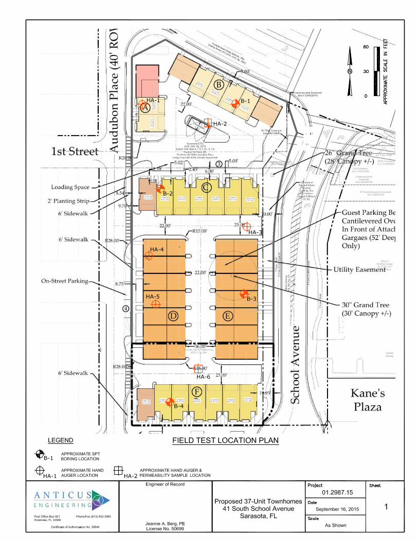
APPENDIX Sheet 1 Field Test Location Plan Sheet 2 Soil Profile Sheet 3 Web Soil Survey/Topographic Map
1
REPORT OF SUBSURFACE EXPLORATION
41 SOUTH SCHOOL AVENUE
SARASOTA, SARASOTA COUNTY, FLORIDA
ANTICUS PROJECT NO. 01.2987.15
1.0 INTRODUCTION
1.1 GENERAL DISCUSSION
Anticus conducted a subsurface exploration for the proposed construction at 41 South School Avenue in Sarasota, Florida. We provided our services in general accordance with our Proposal No. 01.2987.15, dated April 28, 2015 authorized by you utilizing Anticus’s Proposal Acceptance Sheet (PAS). The purpose of the exploration was to evaluate subsurface conditions for the proposed construction and to provide geotechnical engineering recommendations regarding site preparation, earthwork procedures and foundation recommendations for the proposed structures, stormwater vaults and associated pavement areas. This report presents a brief discussion of our understanding of the project, the exploration procedures and results, and our conclusions and recommendations regarding the above considerations.
1.2 REPORT SUMMARY Four (4) Standard Penetration Test (SPT) borings were performed to evaluate the subsurface soils and groundwater conditions with respect to the proposed construction. Additionally, two (2) vertical permeability tests and two (2) horizontal permeability tests were performed to evaluate the permeability rates of the near surface soils and six (6) hand auger borings were performed to further evaluate the shallow subsurface soils and estimate Seasonal High Ground Water Table (SHGWT). The following is an overview of the exploration findings and our geotechnical recommendations. This summary should not be used for planning and design without reading the entire report, which contains more detailed information and assumptions made in developing the recommendations.
1. Groundwater was encountered in our hand auger and SPT borings at depths ranging from 4 to 5.5 feet below existing grade. Based on the Soil Survey of Sarasota County, Florida, prepared by the U.S. Department of Agriculture Natural Resource Conservation Service (NRCS), the historic seasonal high water table (SHGWT) ranges from 0 to 1.5 feet below natural ground surface. This information was consistent with our SHGWT estimates resulting from visual observation of soils from our hand auger borings. The site was previously developed and after additional field sampling, it appears that the soils were disturbed and some fill was used for development, with the estimated current SHGWT of 3.0 to 3.5 feet below existing grades.
2. Structural loads have not been provided. However, it is our understanding that the proposed construction will be CMU block 3-story structures. We have assumed maximum allowable isolated column footing loads will not exceed 250 kips and continuous wall footing loads will not exceed 5 kips per linear foot. The proposed structures can be supported by shallow spread and continuous wall footings designed
Report of Geotechnical Engineering Services September 16, 2015 Proposed 37-Unit Townhome Development Anticus Project No. 01.2987.15
2
for a maximum soil bearing pressure of 2,500 pounds per square foot (psf) after proper subgrade preparation. Based on the loading and the site preparation recommendations contained in this report the total settlement should be less than 1 inch with differential settlement less than ½ of an inch.
3. The preferred soil used for structural fill is fine sand free of organics and debris and containing less than 12 percent material by weight that is finer than a number 200 sieve (fines) (materials conforming to SP and SP-SM in the Unified Soil Classification System [USCS]). SP, SP-SM and SP-SC sand is generally present from the existing ground surface to depths ranging from approximately 22 to 30 feet, and may be used as a source of structural fill. All structural fill should be approved by the Geotechnical Engineer prior to use.
4. Based on the permeability tests performed, the vertical coefficient of permeability ranges between 8 and 9 inches per hour and the horizontal coefficient of permeability ranges between 12 and 13 inches per hour. The soils for permeability testing were sampled at depths ranging between 1.5 and 2 feet below existing grade at locations HA-2 and HA-6, respectively. Please refer to section 5.2 for more detail.
5. A site grading plan is not available at this time. We generally assume that cut and fill in the proposed building areas will be within several feet of existing grades and will be in part controlled by the applicable required separation between the SHGWT and structure floor slabs/pavement base course.
2.0 PROJECT INFORMATION
2.1 EXISTING SITE
The subject property proposed for development is an approximate 1.78 acre parcel, located south of Fruitville Road, west of School Avenue, north of Main Street and west of Audubon Place in Sarasota, Sarasota County, Florida. The site is generally flat and level and of similar elevation as surrounding sites. The site is currently platted as two (2) individual parcels. Based on readily available historical aerial imagery, the site most recently contained three structures with associated asphaltic concrete and Portland cement concrete parking lots. Based on a review of the Sarasota County Property Appraiser’s website, it appears the existing structures were constructed between 1925 and 1951, and development pre-dates the aerial imagery in the area.
2.2 PROPOSED CONSTRUCTION
We understand that the proposed construction will consist of six 3-story structures, associated roadways and access drives and stormwater vaults. Structural loading and grading plans have not been provided at the time of this report. We have assumed wall loads will be a maximum of 5 kips per linear foot and isolated column loads will be a maximum of 250 kips.
Report of Geotechnical Engineering Services September 16, 2015 Proposed 37-Unit Townhome Development Anticus Project No. 01.2987.15
3
3.0 SITE INFORMATION
3.1 SOIL SURVEY INFORMATION
According to the Soil Survey of Sarasota County, Florida, prepared by the U.S. Department of Agriculture Natural Resource Conservation Service (NRCS, formerly the Soil Conservation Service), the subject property is primarily underlain by one soil type: EauGallie and Myakka fine sands (Unit 10). The general soil descriptions as described in the Soil Survey are presented in the following table.
SUMMARY OF USDA SOIL SURVEY
SARASOTA COUNTY, FLORIDA
USDA Map Symbol and Soil
Name
Depth (in)
Soil Classification
Permeability (in/hr) pH
Seasonal High Water Table Risk of Corrosion
USCS AASHTO Depth (feet) Months Uncoated
Steel Concrete
(10) EauGallie
& Myakka
0-6 SP, SP-SM A-3 6.0 - 20.0 4.5-6.0
0.0-1.5 June-Sept High High
6-22 SP, SP-SM A-3 6.0 - 20.0 4.5-6.0
22-44 SM, SP-SM A-2-4, A-3 0.6 - 6.0 4.5-6.5
44-48 SP, SP-SM A-2-4, A-3 6.0 - 20.0 4.5-7.8
48-66 SC, SC-SM, SM A-2-4, A-2-6 0.1 - 0.6 4.5-7.8
66-80 SC, SC-SM, SM A-2-4, A-2-6 0.6 - 6.0 4.5-7.8
0-6 SP, SP-SM A-3 6.0 - 20.0 3.5-6.5
0.0-1.5 June-Sept High High 6-24 SP, SP-SM A-3 6.0 - 20.0 3.5-6.5
24-42 SM, SP-SM A-2-4, A-3 0.6 - 6.0 3.5-6.5
42-80 SP, SP-SM A-3 6.0 - 20.0 3.5-6.5
4.0 EXPLORATION AND TESTING METHODS
Six (6) hand auger borings were performed by manually twisting a post-hole auger into the soil. The auger consists of two curved blades and a bucket which retains the soil as the auger is advanced. At approximately 6 inch intervals the auger is removed and the soil retained in the bucket is classified and placed in sealed containers for further evaluation by a geotechnical engineer. The soils encountered in the boring were classified utilizing the Unified Soil Classification System (USCS).
Four (4) Standard Penetration Test (SPT) borings were drilled with a track-mounted drilling rig - at the location shown on the attached Boring Location Plan. The SPT borings were performed and split-barrel soil samples obtained at intervals of 2 feet to a depth of 10 feet and intervals of 5 feet thereafter. Conventional rotary drilling procedures were utilized along with a bentonite drilling fluid to stabilize the boreholes.
The following is a brief description of this field test procedure. The exploratory borings were performed in accordance with ASTM D 1586, entitled "Standard Method for Penetration Test and Split-Barrel Sampling of Soils.” After drilling to the required depth and cleaning the bore hole, the sampler (2" O.D.) was driven 18 or 24 inches into the undisturbed soil by a 140-pound
Report of Geotechnical Engineering Services September 16, 2015 Proposed 37-Unit Townhome Development Anticus Project No. 01.2987.15
4
drop-hammer falling 30 inches. The number of blows required to drive the sampler the second and third 6-inch increments is known as the Standard Penetration Resistance (N). The various soils encountered in the borings were visually classified in the field and representative soil samples obtained for further examination by a Geotechnical Engineer. The soils encountered in the borings were classified utilizing the USCS. At the completion of the drilling operations, the boreholes were abandoned in accordance with Southwest Florida Water Management District guidelines.
Two (2) vertical permeability tests and two (2) horizontal permeability tests were conducted in general accordance with Florida Method Designation FM-5-513 (Falling Head Method) to determine the coefficient of vertical and horizontal permeability (KV and KH, respectively). The samples were collected in the field with Shelby tube drive sleeves at the locations shown on the attached Field Test Location Plan, Sheet 1. The samples were collected near the SHGWT depth. The generally undisturbed samples were transported back to our laboratory for permeability testing.
The procedures used by Anticus for field sampling and testing are in general accordance with ASTM and Florida Method procedures and established engineering practice.
4.1 FIELD EXPLORATION AND TESTING
Six (6) hand auger borings (HA-1 through HA-6) were performed to approximate depths ranging from 4 to 5 feet below existing ground surface. Borings HA-2 and HA-6 were performed to evaluate the shallow soil conditions revealed in the survey and to determine the estimated SHGWT.
Four (4) SPT borings were advanced to approximate depths of 35 feet below the existing ground surface to evaluate the soil characteristics at the site. The drillers advanced the borings using wet rotary methods and collected soil samples using a split-barrel sampler driven by a cathead and safety hammer system according to ASTM D1586.
The SPT borings, hand auger borings and permeability sample locations were located by using a handheld GPS unit. Therefore, the field test locations shown on the attached Field Test Location Plan should be considered as approximate.
The Soil Profile, Sheet 2 of the attachments, represents our interpretation of the conditions encountered at each boring location. The stratification lines indicated on the Soil Profile represent the approximate boundaries between soil types; however these transitions may be more gradual than indicated.
5.0 SUBSURFACE CONDITIONS
5.1 GENERAL SOIL PROFILE
Hand auger borings HA-1 through HA-6 generally encountered SAND to SAND With Silt (SP/SP-SM) to the boring termination depths of approximately 4 to 5 feet below existing grade.
SPT borings B-1 through B-4 generally encountered loose to very dense SAND to SAND With Silt (SP/SP-SM) to depths of approximately 22 to 30 feet; sometimes interlayered with loose
Report of Geotechnical Engineering Services September 16, 2015 Proposed 37-Unit Townhome Development Anticus Project No. 01.2987.15
5
SAND With Clay (SP-SC); underlain by firm to hard Silty CLAY (CL/CH) and/or loose to very dense Clayey SAND (SC) to the boring termination depths of approximately 35 feet.
The above discussion provides only a brief and general description of subsurface conditions encountered in the borings. Detailed descriptions are presented on the attached soil profile. When reviewing the soil profile, the indicated boundaries between soil strata are approximate and the transitions between strata are typically more gradual. Also, variations in subsurface conditions from those encountered may exist between the boring locations.
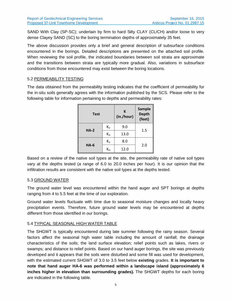
5.2 PERMEABILITY TESTING
The data obtained from the permeability testing indicates that the coefficient of permeability for the in-situ soils generally agrees with the information published by the SCS. Please refer to the following table for information pertaining to depths and permeability rates:
Test K
(in./hour)
Sample
Depth
(feet)
HA-2 KV 9.0
1.5 KH 13.0
HA-6 KV 8.0
2.0 KH 12.0
Based on a review of the native soil types at the site, the permeability rate of native soil types vary at the depths tested (a range of 6.0 to 20.0 inches per hour). It is our opinion that the infiltration results are consistent with the native soil types at the depths tested.
5.3 GROUND WATER
The ground water level was encountered within the hand auger and SPT borings at depths ranging from 4 to 5.5 feet at the time of our exploration.
Ground water levels fluctuate with time due to seasonal moisture changes and locally heavy precipitation events. Therefore, future ground water levels may be encountered at depths different from those identified in our borings.
5.4 TYPICAL SEASONAL HIGH WATER TABLE
The SHGWT is typically encountered during late summer following the rainy season. Several factors affect the seasonal high water table including the amount of rainfall; the drainage characteristics of the soils; the land surface elevation; relief points such as lakes, rivers or swamps; and distance to relief points. Based on our hand auger borings, the site was previously developed and it appears that the soils were disturbed and some fill was used for development, with the estimated current SHGWT of 3.0 to 3.5 feet below existing grades. It is important to note that hand auger HA-6 was performed within a landscape island (approximately 6 inches higher in elevation than surrounding grades). The SHGWT depths for each boring are indicated in the following table.
Report of Geotechnical Engineering Services September 16, 2015 Proposed 37-Unit Townhome Development Anticus Project No. 01.2987.15
6
Boring HA-2 HA-6
SHGWT Depth (feet) 3.0 3.5
6.0 CONCLUSIONS
We base the following conclusions in part on the preceding project information and the results of the subsurface exploration. The following describes our conclusions concerning geotechnical issues associated with the project:
The preferred soil used for structural fill is fine sand free of organics and debris and containing less than 12 percent material by weight that is finer than a number 200 sieve (fines) (materials conforming to SP and SP-SM in the USCS). SP, SP-SM and SP-SC sand is generally present from the existing ground surface to depths of approximately 22 to 30 feet, and may be used as a source of structural fill. All structural fill material should be approved by the Geotechnical Engineer prior to use.
Based on the hand auger borings performed at the site, the SHGWT is approximately 3.0 to 3.5 feet below existing grade. It is important to note that hand auger HA-6 was performed within a landscape island (approximately 6 inches higher in elevation than surrounding grades). We recommend at least 18 inches of separation between the bottom of limerock road base and the SHGWT.
7.0 RECOMMENDATIONS
7.1 SITE PREPARATION
7.1.1 Site Stripping
To prepare the site for construction, all existing building remnants from demolition, vegetation and large root systems should be removed. All existing utilities (including septic tanks and lines, if any) should be abandoned properly. After stripping, any pockets of organic debris/deleterious materials should be undercut. The resulting excavation should be backfilled with soils as discussed in the structural fill section of this report. As a minimum, it is recommended that the clearing operations extend at least five (5) feet beyond the development perimeters.
7.1.2 Subgrade Preparation and Fill Placement
Following the clearing operations, the exposed existing subgrade should be evaluated and proofrolled as directed by representatives of Anticus to confirm that all unsuitable materials have been removed. The proofrolling should consist of compaction using a large diameter, heavy vibratory drum roller. The vibratory drum roller should have a static drum weight on the order of eight (8) to ten (10) tons and should be capable of exerting a minimum impact force of 36,000 pounds (DYNAPAC CA-250 or equivalent); this is expected to provide adequate results. The vibratory roller should not be used within 50 feet of existing structures (if any). These areas should be compacted using a fully loaded 2 cubic yard capacity front-end loader or equivalent.
Proofrolling should be closely monitored by our engineering technician to observe for unusual deflection of the soils beneath the wheel loads. If unusual or excessive deflection is observed,
Report of Geotechnical Engineering Services September 16, 2015 Proposed 37-Unit Townhome Development Anticus Project No. 01.2987.15
7
then the areas should be undercut to firm soils and backfilled with structural fill placed in maximum one-foot thick loose lifts. The proofrolling equipment should make a minimum of eight (8) overlapping passes over the structure areas and pavement areas with the successive passes aligned perpendicular. It is recommended that within the building and pavement areas, the natural ground, to a minimum depth of one (1) foot below stripped grade, be compacted to a dry density of at least 95% of the modified Proctor maximum dry density.
Following satisfactory completion of the initial proofrolling, the structure and pavement areas may be brought up to finished subgrade levels, as needed. Backfill soils and soils used to bring the structure area up to finished subgrade levels should be of the same composition and be compacted to the same criteria as structural fill soils, as subsequently discussed. If soft pockets are encountered in the footing excavations, the unsuitable materials should be removed and the proposed footing elevation may be re-established by backfilling after the undesirable material has been removed. This backfilling may be done with a very lean concrete or with a well-compacted, suitable fill such as clean sand, gravel, or crushed FDOT No. 57 or FDOT No. 67 stone. Sand backfill should be compacted to a minimum density of 95% of the modified Proctor maximum dry density.
Approved sand fill should be placed in loose lifts not exceeding 12 inches in thickness and should be compacted to a minimum density of 95% of the modified Proctor maximum dry density. Density tests to confirm compaction should be performed in each fill lift before the next lift is placed. Prior to beginning compaction, soil moisture contents may need to be controlled in order to facilitate proper compaction. If additional moisture is necessary to achieve compaction objectives, then water should be applied in such a way that it will not cause erosion or removal of the subgrade soils. Moisture content within the percentage range needed to achieve compaction is recommended prior to compaction of the natural ground and fill.
After compaction and proofrolling, the building foundation excavations can begin. Foundation excavations should be observed by the geotechnical engineer or a representative to explore the extent of any loose, soft, or otherwise undesirable materials. If the foundation excavations appear suitable as load bearing materials, the bottom of the foundation excavations should be compacted to a minimum density of 95 percent of the modified Proctor maximum dry density for a minimum depth of one (1) foot below the bottom of the footing depth, as determined by field density compaction tests.
Backfill soils placed adjacent to footings or walls should be carefully compacted with a light rubber-tired roller or vibratory plate compactor to avoid damaging the footings or walls. Approved sand fills to provide foundation embedment constraint should be placed in loose lifts not exceeding 6 inches and should be compacted to a minimum density of 95 percent of the modified Proctor maximum dry density.
Immediately prior to reinforcing steel placement, it is suggested that the bearing surfaces of all footing and floor slab areas be compacted using hand operated mechanical tampers. In this manner, any localized areas which have been loosened by excavation operations should be adequately recompacted.
Report of Geotechnical Engineering Services September 16, 2015 Proposed 37-Unit Townhome Development Anticus Project No. 01.2987.15
8
7.2 STRUCTURAL FILL
7.2.1 Structural Fill Definition
The preferred soil used for structural fill is fine sand free of organics and debris and containing less than 12 percent material by weight that is finer than a number 200 sieve (fines) (materials conforming to SP and SP-SM in the USCS). All fill should be approved by the Geotechnical Engineer before placement.
7.2.2 Structural Fill Availability
SP, SP-SM and SP-SC sand are generally present from the existing ground surface to depths of approximately 22 to 30 feet, and may be used as a source of building structural fill.
7.2.3 Structural Fill Placement and Compaction
Structural fill with less than 12 percent fines should be placed in lifts not to exceed one foot thick. The fill material should be compacted to at least 95 percent of its modified Proctor maximum dry density (ASTM D-1557). We recommend the upper 1-foot below the floor slab be compacted to at least 95 percent of modified Proctor maximum dry density.
7.3 SITE DEGRADATION DURING CONSTRUCTION
It has been our experience that prior to slab construction, slab subgrades can be significantly disrupted by construction equipment, utility construction, and inclement weather. The soils exposed at the slab subgrade will consist primarily of sands. These materials are particularly susceptible to disturbance. Placement of concrete or fill upon these areas must occur promptly, or these areas will need re-compaction and re-testing.
7.4 SPREAD FOUNDATIONS
Based on the information revealed by our exploration, the 3-story structures can be supported by a continuous strip footings bearing on densified residual soil. We recommend use of a maximum allowable net soil bearing pressure of 2,500 psf to size column and strip footings supported by these materials. Total settlement is anticipated to be less than 1 inch with differential settlement less than ½ inch.
Even though computed footing dimensions may be less, column footings should have a minimum width of at least 24 inches and strip footings should be at least 24 inches wide. These dimensions facilitate densification and hand cleaning of footing subgrades disturbed by the excavation process and the placement of reinforcing steel. They also reduce the potential for localized punching shear failure. Footings should bear at least 18 inches below the finished exterior grade as a bearing capacity requirement.
Foundation excavation will produce a thin veneer of disturbed soil at the footing subgrade. We recommend that the surficial soils exposed at the bottom of the foundation excavation be compacted to at least 95 percent of the soil's modified Proctor maximum dry density. Hand guided vibrating plates can be used. The compaction should be performed and checked prior to placement of reinforcing steel.
Report of Geotechnical Engineering Services September 16, 2015 Proposed 37-Unit Townhome Development Anticus Project No. 01.2987.15
9
7.5 FLOOR SLAB
We assess that no unusual floor loads will be applied to the floor slab. No extraordinary floor slab performance criteria, such as very low allowable deflection/settlement, are expected. The upper 1-foot of soil beneath the slab area should be compacted to at least 95 percent of its modified Proctor maximum dry density. To reduce the possibility of slab cracking due to minor differential settlement, transitions from foundation-supported building elements to soil supported building elements should be reinforced.
Use of a vapor retarder should be determined by the structural engineer. Any vapor retarder should be placed in accordance with ACI guidelines.
It has been our experience that prior to slab construction, slab subgrades can be significantly disrupted by construction equipment, utility construction, and inclement weather. The soils exposed at the slab subgrade will consist primarily of sands. These materials are particularly susceptible to disturbance. Placement of concrete in these areas must occur promptly, or these areas will likely need re-compaction and re-testing.
7.6 PAVEMENT
The recommended pavement sections have been based on traffic patterns that we believe are consistent with similar developments and site conditions, assuming maximum 20 year, 18,000 pound single axle loads (Light Duty classification), and Heavy Duty Classification with an ADT volume of 100,000 for entrance/exit areas. These design parameters need to be verified by the design Engineer once actual traffic loading conditions become available.
We have also assumed that compacted fill material in pavement areas will exhibit an LBR value of at least 20. If site preparation work is performed as described above, the following pavement sections may be utilized:
Section Description Flexible Pavement Sections
Thickness (in)
Light Duty Heavy Duty
Surface Course
1.5 2 Type S-1 or S-3 Asphaltic Concrete with minimum stability of 1500 lbs.
Compacted to at least 96% of the maximum laboratory density.
Base Course (1) 6 8 Limerock having a minimum LBR of 100 and compacted to at least 98% of the
modified Proctor maximum dry density (ASTM D-1557). Subbase
12 12 In-situ soils compacted to at least 95% of the modified Proctor maximum dry
density (ASTM D-1557).
(1) Limerock base course requires a minimum separation of 18 inches between the bottom of base and the SHGWT.
Note that the common base course material in Florida (limerock) is not free draining and deteriorates if in contact with water.
Report of Geotechnical Engineering Services September 16, 2015 Proposed 37-Unit Townhome Development Anticus Project No. 01.2987.15
10
The performance of the pavement sections is highly dependent on controlling the moisture of the subgrade soils. It is important that surface drainage be controlled to prevent water from ponding in pavement areas. If free draining material is to be employed we suggest crushed recycled concrete.
The choice of pavement base type will depend on final pavement grades. If a minimum separation of 18 inches between the bottom of the base and the seasonal high groundwater level is obtained, then a limerock, shell, or crushed concrete base can be utilized (thickness as noted above). A soil cement base should be utilized if the separation between final grade and the seasonal high groundwater is a minimum of 12 inches and less than 18 inches. Base material elevations should not be designed for saturated conditions. If the designer wishes to have base material closer than 12 inches to the SHGWT, then an underdrain system should be utilized that will maintain the 12 inches of separation. The SHGWT should be re-established relative to a known elevation prior to setting final grades.
A soil cement base should be designed according to FDOT or PCA modified short cut design procedures. Strength of 300 psi should be achieved on laboratory cured compressive strength specimens molded from samples taken from the base material as it is placed. A stabilized subgrade need not be incorporated with a soil cement base. Traffic should not be allowed on the subgrade as the base is placed to avoid rutting. Before paving, the subgrade should be checked for soundness and be true to line and grade prior to paving.
Crushed concrete should be graded in accordance with FDOT Standard Specification Section 901-5. As a guideline for pavement design, we recommend that the base course be a minimum of 6 inches thick in parking areas and 8 inches thick in heavily traveled drives. Before paving, the base should be checked for soundness.
The above light duty pavement section is based on the assumption that this area will receive virtually no truck traffic. If it is subjected to truck traffic, then heavy-duty pavement should be used. We recommend that a confirmatory LBR test be performed prior to paving. If the LBR test indicates a value less than 20, thicker pavement sections will be required.
This approach projects an approximate pavement life of 20 years, provided there are no major changes in the project characteristics. We expect that the pavement will not be maintenance free. Any distressed areas should be promptly repaired to prevent the failure from spreading due to loading and water infiltration. Cracks and joints should be sealed annually.
7.7 EARTH SLOPE RECOMMENDATIONS
Stability of a slope depends on many factors including the geometry of the slopes, height of the slope, type of soils and surface pressures, if any. Therefore, the maximum slope for fill and virgin soils should not exceed 1 vertical (V):2 horizontal (H) for temporary embankments and 1V:3H for permanent embankments.
We recommend a building setback of at least 10 feet from the tops of all slopes and a setback of at least 3 feet for parking area curbs. Drop inlets or storm sewers should not be installed at the crests of slopes because leakage can result in maintenance problems or possible slope failure. Crest areas should be sloped to prevent surface runoff from flowing over the slope faces.
Report of Geotechnical Engineering Services September 16, 2015 Proposed 37-Unit Townhome Development Anticus Project No. 01.2987.15
11
It is difficult to construct fill on the specified slopes without leaving a loose, poorly compacted zone on the slope face. For this reason, we recommend that the fill slopes be slightly over-build, then cut back to firm, well compacted soils prior to applying a vegetative cover. If the slopes cannot be slightly over-built and cut back, we recommend that finished soil slopes be compacted to reduce, as much as practical, the thickness of this soft surficial veneer.
7.8 EXCAVATIONS
In general, structural fill will be excavated from the ponds for this project and should consist of fine sands (SP/SP-SM), which can be moved and used for grading purposes, site leveling, general engineering fill, structural fill and backfill in other areas, provided the fill is free of organic materials, clay, debris or any other material deemed unsuitable for construction. All fill should be placed in accordance with the recommendations provided in this report.
In Federal Register, Volume 54, No. 209 (October 1989), the United States Department of Labor, Occupational Safety and Health Administration (OSHA) amended its “Construction Standards for Excavations, 29 CFR, Part 1926, Subpart P”. This document was issued to better insure the safety of workmen entering trenches or excavations. It is mandated by this federal regulation that excavations, whether they be utility trenches, basement excavations or foundation excavations, be constructed in accordance with the new OSHA guidelines. It is our understanding that these regulations are being strictly enforced and if they are not closely followed, the owner and the contractor could be liable for substantial penalties.
The contractor is solely responsible for designing and constructing stable, temporary excavations and should shore, slope, or bench the sides of the excavations as required to maintain stability of both the excavation sides and bottom. The contractors “responsible persons”, as defined in 29 CFR Part 1926, should evaluate the soil exposed in the excavations as part of the contractor’s safety procedures. In no case should slope height, slope inclination, or excavation depth, including utility trench excavation depth, exceed those specified in all local, state, and federal safety regulations.
We are providing this information solely as a service to our client. Anticus Engineering, LLC does not assume responsibility for construction site safety or the contractor’s or other party’s compliance with local, state, and federal safety or other regulations.
8.0 FOLLOW-UP SERVICES
Our services do not end with the submission of this geotechnical report. Anticus should be kept involved throughout the design and construction process to maintain continuity and to verify that our recommendations are properly interpreted and implemented. To achieve this, we should review project plans and specifications with the designers to see that our recommendations are fully incorporated. We also should be retained to monitor and test the site preparation and foundation construction.
Anticus’s familiarity with the site and with the foundation recommendations makes us a valuable part of your construction quality assurance team. Anticus recommends that we be retained by the owner to observe earthwork and foundation construction. Our personnel are uniquely
Report of Geotechnical Engineering Services September 16, 2015 Proposed 37-Unit Townhome Development Anticus Project No. 01.2987.15
12
qualified to recognize unanticipated ground conditions and can offer responsive remedial recommendations should these unanticipated conditions occur.
9.0 LIMITATIONS OF REPORT
This report has been prepared for the exclusive use of ICON Real Estate Ventures, Inc. and its designers for specific application to the project previously discussed. Our conclusions and recommendations have been prepared using generally accepted standards of geotechnical engineering and engineering geology practice in the State of Florida. No other warranty is expressed or implied.
Our conclusions and recommendations are based on the design information furnished to us, the data obtained from the previously described exploration and our experience. They do not necessarily reflect variations in the subsurface conditions, which are likely to exist intermediate of our borings and in unexplored areas of the site due to the inherent variability of the subsurface conditions in this geologic region as well as past land use. Should such variations become apparent during construction, it will be necessary to re-evaluate our conclusions and recommendations based upon on-site observation of the conditions.
If changes are made in the overall design or location of the building and grading scheme, then the recommendations presented in this report may no longer be valid. In such cases, our firm should review the proposed changes to evaluate whether our recommendations need to be modified. The results of this review should be provided in writing. We also request the opportunity to review the foundation plan, grading plan and applicable portions of the project specifications when the design is finalized. This review will allow us to check whether these documents are consistent with the intent of our recommendations.
Sampling and testing of the soil, rock, ground water, surface water and air for the presence of environmental contamination was beyond the scope of this exploration. We will be glad to provide these services at your request.
The site is underlain by limestone bedrock that is susceptible to dissolution and the subsequent development of karst features such as voids and sinkholes in the natural soil overburden. Construction in a sinkhole prone area is therefore accompanied by some risk that internal soil erosion and ground subsidence could affect new structures in the future. It is not possible to investigate or design to completely eliminate the possibility of future sinkhole related problems. In any event, the Owner must understand and accept this risk.