20
REPORT OF SUBSURFACE EXPLORATION 245 & 310 SCOFIELD STORMMWATER IMPROVEMENTS CHARLOTTE, NORTH CAROLINA CAPSTONE PROJECT NO. 100-14-004A PREPARED FOR: May 8, 2017

REPORT OF SUBSURFACE EXPLORATION
245 & 310 SCOFIELD STORMMWATER IMPROVEMENTS
CHARLOTTE, NORTH CAROLINA
CAPSTONE PROJECT NO. 100-14-004A
PREPARED FOR:
May 8, 2017

CHARLOTTE
2020 N. Tryon Street
Charlotte, NC 28215
Tel: 980.938.6770
www.capstonecivilcompanies.com
May 8, 2017
Mr. David Bocker, PE
CALYX
7500 E. Independence Blvd Siute100
Charlotte, NC 28227
Reference: Report of Subsurface Exploration
Scofield Stormwater Improvements
Charlotte, North Carolina Capstone Project No. 100-14-004A
Dear Mr. Bocker:
Capstone Civil Engineering, Inc. (CAPSTONE) has completed the subsurface
exploration and geotechnical analysis for the above referenced project in
Charlotte, North Carolina. This report contains a brief description of the
project information provided to us, general description of the site subsurface
soil conditions encountered during our subsurface exploration, and our
geotechnical design recommendations for the proposed storm water
improvement project.
We are available to review with you the recommendations presented herein
and answer questions you may have. We have enjoyed working with you and
look forward to our continued association as your geotechnical consultant on
the remainder of this project and any future projects you may have.
Should you have any questions regarding this report or if we may be of further
assistance, please feel free to contact us at your convenience.
Respectfully,
Capstone Civil Engineering, Inc.
Charles M. Brown, Jr., PE
Principal Engineer
CAPSTONE - top
stone: a stone used
at the top of a wall
or another structure
- high point:
something
considered the
highest
achievement or
most important
action in a series of
actions
5-8-17
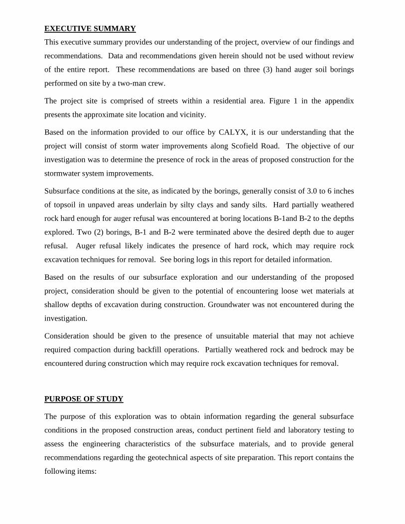
EXECUTIVE SUMMARY
This executive summary provides our understanding of the project, overview of our findings and
recommendations. Data and recommendations given herein should not be used without review
of the entire report. These recommendations are based on three (3) hand auger soil borings
performed on site by a two-man crew.
The project site is comprised of streets within a residential area. Figure 1 in the appendix
presents the approximate site location and vicinity.
Based on the information provided to our office by CALYX, it is our understanding that the
project will consist of storm water improvements along Scofield Road. The objective of our
investigation was to determine the presence of rock in the areas of proposed construction for the
stormwater system improvements.
Subsurface conditions at the site, as indicated by the borings, generally consist of 3.0 to 6 inches
of topsoil in unpaved areas underlain by silty clays and sandy silts. Hard partially weathered
rock hard enough for auger refusal was encountered at boring locations B-1and B-2 to the depths
explored. Two (2) borings, B-1 and B-2 were terminated above the desired depth due to auger
refusal. Auger refusal likely indicates the presence of hard rock, which may require rock
excavation techniques for removal. See boring logs in this report for detailed information.
Based on the results of our subsurface exploration and our understanding of the proposed
project, consideration should be given to the potential of encountering loose wet materials at
shallow depths of excavation during construction. Groundwater was not encountered during the
investigation.
Consideration should be given to the presence of unsuitable material that may not achieve
required compaction during backfill operations. Partially weathered rock and bedrock may be
encountered during construction which may require rock excavation techniques for removal.
PURPOSE OF STUDY
The purpose of this exploration was to obtain information regarding the general subsurface
conditions in the proposed construction areas, conduct pertinent field and laboratory testing to
assess the engineering characteristics of the subsurface materials, and to provide general
recommendations regarding the geotechnical aspects of site preparation. This report contains the
following items:
Scofield SDIP
Charlotte, North Carolina
Capstone Project No: 100-14-004A
Page 2
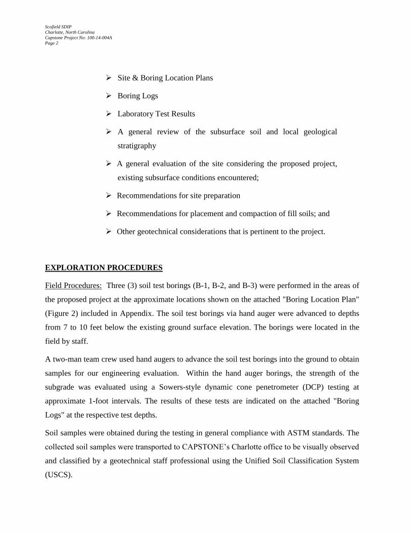
Site & Boring Location Plans
Boring Logs
Laboratory Test Results
A general review of the subsurface soil and local geological
stratigraphy
A general evaluation of the site considering the proposed project,
existing subsurface conditions encountered;
Recommendations for site preparation
Recommendations for placement and compaction of fill soils; and
Other geotechnical considerations that is pertinent to the project.
EXPLORATION PROCEDURES
Field Procedures: Three (3) soil test borings (B-1, B-2, and B-3) were performed in the areas of
the proposed project at the approximate locations shown on the attached "Boring Location Plan"
(Figure 2) included in Appendix. The soil test borings via hand auger were advanced to depths
from 7 to 10 feet below the existing ground surface elevation. The borings were located in the
field by staff.
A two-man team crew used hand augers to advance the soil test borings into the ground to obtain
samples for our engineering evaluation. Within the hand auger borings, the strength of the
subgrade was evaluated using a Sowers-style dynamic cone penetrometer (DCP) testing at
approximate 1-foot intervals. The results of these tests are indicated on the attached "Boring
Logs" at the respective test depths.
Soil samples were obtained during the testing in general compliance with ASTM standards. The
collected soil samples were transported to CAPSTONE’s Charlotte office to be visually observed
and classified by a geotechnical staff professional using the Unified Soil Classification System
(USCS).
Scofield SDIP
Charlotte, North Carolina
Capstone Project No: 100-14-004A
Page 3
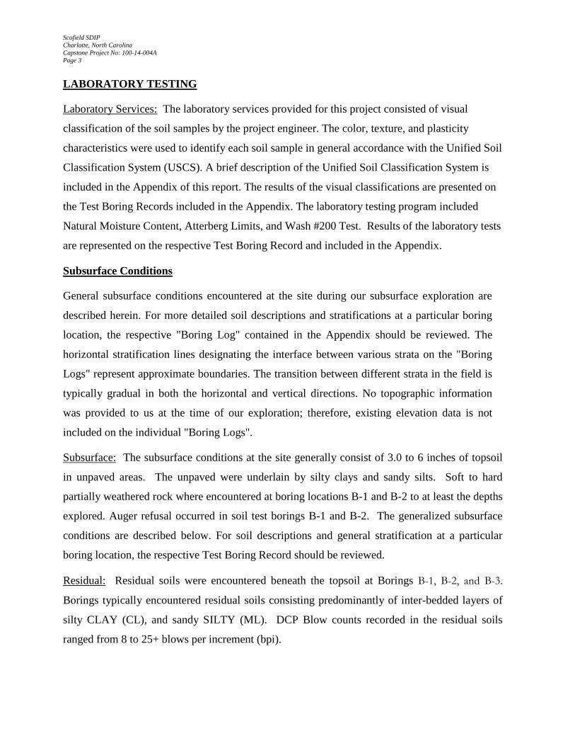
LABORATORY TESTING
Laboratory Services: The laboratory services provided for this project consisted of visual
classification of the soil samples by the project engineer. The color, texture, and plasticity
characteristics were used to identify each soil sample in general accordance with the Unified Soil
Classification System (USCS). A brief description of the Unified Soil Classification System is
included in the Appendix of this report. The results of the visual classifications are presented on
the Test Boring Records included in the Appendix. The laboratory testing program included
Natural Moisture Content, Atterberg Limits, and Wash #200 Test. Results of the laboratory tests
are represented on the respective Test Boring Record and included in the Appendix.
Subsurface Conditions
General subsurface conditions encountered at the site during our subsurface exploration are
described herein. For more detailed soil descriptions and stratifications at a particular boring
location, the respective "Boring Log" contained in the Appendix should be reviewed. The
horizontal stratification lines designating the interface between various strata on the "Boring
Logs" represent approximate boundaries. The transition between different strata in the field is
typically gradual in both the horizontal and vertical directions. No topographic information
was provided to us at the time of our exploration; therefore, existing elevation data is not
included on the individual "Boring Logs".
Subsurface: The subsurface conditions at the site generally consist of 3.0 to 6 inches of topsoil
in unpaved areas. The unpaved were underlain by silty clays and sandy silts. Soft to hard
partially weathered rock where encountered at boring locations B-1 and B-2 to at least the depths
explored. Auger refusal occurred in soil test borings B-1 and B-2. The generalized subsurface
conditions are described below. For soil descriptions and general stratification at a particular
boring location, the respective Test Boring Record should be reviewed.
Residual: Residual soils were encountered beneath the topsoil at Borings B-1, B-2, and B-3.
Borings typically encountered residual soils consisting predominantly of inter-bedded layers of
silty CLAY (CL), and sandy SILTY (ML). DCP Blow counts recorded in the residual soils
ranged from 8 to 25+ blows per increment (bpi).

Scofield SDIP
Charlotte, North Carolina
Capstone Project No: 100-14-004A
Page 4
Hard Partially Weathered Rock: Material hard enough to classify as hard partially weathered
rock was encountered below the residual soils at boring B-1 and B-2. The top of the hard
partially weathered rock occurred at depths of from approximately 7 feet below the existing
ground at both locations. Hard partially weathered rock was defined as residual material that
exhibited auger refusal and DCP blow counts 25+ blows to advance DCP less than 1 inch.
The hard partially weathered rock represents the transition between hard weathered rock and
bedrock.
Groundwater Observations: Groundwater measurements were attempted at the termination of
operations and again at the end of the day prior to demobilization. No groundwater was
encountered. Borings were backfilled at the completion of auger activities.
In general, groundwater movement within the soils overlying bedrock is controlled largely by
topographic gradients. Movement in this water table is generally from higher to lower elevations.
Recharge occurs primarily by infiltration along higher elevations and typically discharges into
streams or other surface water bodies. Please keep in mind that groundwater levels can vary
greatly with seasonal fluctuations in precipitation, surface water runoff, type of construction
operations, and other factors. Normally the highest groundwater levels occur in the late winter
and spring and the lowest groundwater levels occur in the late summer and fall. Therefore
groundwater may be encountered during construction at depths not indicated during this
exploration.
Engineering Recommendations
Our evaluations and recommendations are based on the project information outlined previously
and on the data obtained from field exploration and laboratory testing. If the geometry, location
or loading conditions for the proposed structure provided with this report change, or if conditions
are encountered during construction that differ from those encountered at the soil test boring
location,
CAPSTONE request the opportunity to review our recommendations based on the differing
conditions and make the necessary changes to this report. The assessment of site environmental
conditions for the presence of pollutants in the soil, rock, and ground water of the site was
beyond the scope of this exploration.
Scofield SDIP
Charlotte, North Carolina
Capstone Project No: 100-14-004A
Page 5
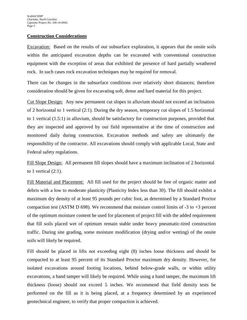
Construction Considerations
Excavation: Based on the results of our subsurface exploration, it appears that the onsite soils
within the anticipated excavation depths can be excavated with conventional construction
equipment with the exception of areas that exhibited the presence of hard partially weathered
rock. In such cases rock excavation techniques may be required for removal.
There can be changes in the subsurface conditions over relatively short distances; therefore
consideration should be given for excavating soft, dense and hard material for this project.
Cut Slope Design: Any new permanent cut slopes in alluvium should not exceed an inclination
of 2 horizontal to 1 vertical (2:1). During the dry season, temporary cut slopes of 1.5 horizontal
to 1 vertical (1.5:1) in alluvium, should be satisfactory for construction purposes, provided that
they are inspected and approved by our field representative at the time of construction and
monitored daily during construction. Excavation methods and safety are ultimately the
responsibility of the contractor. All excavations should comply with applicable Local, State and
Federal safety regulations.
Fill Slope Design: All permanent fill slopes should have a maximum inclination of 2 horizontal
to 1 vertical (2:1).
Fill Material and Placement: All fill used for the project should be free of organic matter and
debris with a low to moderate plasticity (Plasticity Index less than 30). The fill should exhibit a
maximum dry density of at least 95 pounds per cubic foot, as determined by a Standard Proctor
compaction test (ASTM D 698). We recommend that moisture control limits of -3 to +3 percent
of the optimum moisture content be used for placement of project fill with the added requirement
that fill soils placed wet of optimum remain stable under heavy pneumatic-tired construction
traffic. During site grading, some moisture modification (drying and/or wetting) of the onsite
soils will likely be required.
Fill should be placed in lifts not exceeding eight (8) inches loose thickness and should be
compacted to at least 95 percent of its Standard Proctor maximum dry density. However, for
isolated excavations around footing locations, behind below-grade walls, or within utility
excavations, a hand tamper will likely be required. While using a hand tamper, the maximum lift
thickness (loose) should not exceed 5 inches. We recommend that field density tests be
performed on the fill as it is being placed, at a frequency determined by an experienced
geotechnical engineer, to verify that proper compaction is achieved.

Scofield SDIP
Charlotte, North Carolina
Capstone Project No: 100-14-004A
Page 6
While compacting adjacent to below-grade walls, heavy construction equipment should maintain
a horizontal distance of 1 (H):1(V). If this minimum distance cannot be maintained, the
compaction equipment should run perpendicular, not parallel to, the long axis of the wall.
Construction Monitoring and Quality Control
We recommend that a geotechnical and construction material testing firm be employed to
monitor and to report that the recommendations concerning infrastructure support are completed
in a satisfactory manner. Our continued involvement on the project helps provide continuity for
proper implementation of the recommendations discussed herein. The following is a
recommended scope of service:
Review project plans and construction specifications to assess the interpretation of
this report;
Observe the excavation process to document that subsurface conditions
encountered during construction are consistent with the conditions anticipated in
this report;
Observe the subgrade before placing fill and observe all foundations for
conformance with recommended bearing stratum;
Observe the placement and compaction of any engineered fill soils and perform
laboratory and field compaction testing of the fill soils.
Limitations
This report has been prepared for the exclusive use of CALYX, or its agents, for the specific
application to the proposed stormwater improvements along Scofield Drive located in Charlotte,
North Carolina. No other warranty, expressed or implied, is made. Our assessment and
recommendations are based on information furnished to us or on educated assumptions, data
from this geotechnical exploration, and generally accepted geotechnical engineering practice.
The evaluations and recommendations do not reflect variations in subsurface conditions which
could exist intermediate of the boring locations or in unexplored areas of the site. Should such
variations become apparent during construction, it will be necessary to re-evaluate our
evaluations and recommendations based upon on-site observations or the conditions
encountered.
Scofield SDIP
Charlotte, North Carolina
Capstone Project No: 100-14-004A
Page 7
Regardless of the thoroughness of the subsurface exploration, there is the possibility that
conditions between borings will differ from those at the boring locations, that conditions are not
as anticipated by the designers, or that the construction process has altered the soil conditions.
Therefore, an experienced staff professional working under the supervision of a geotechnical
engineer should evaluate earthwork and foundation construction to verify that the conditions
anticipated in design actually exist. Otherwise, we assume no responsibility for construction
compliance with the design concepts, specifications or recommendations.
In the event that the actual design differs from the assumptions contained herein or if the location
of the proposed structure changes, the recommendations presented in this report shall not be
considered valid unless the changes are reviewed by our firm and evaluations of this report
modified and/or verified in writing. If this report is copied or transmitted to a third party, it must
be copied or transmitted in its entirety, including text, attachments and enclosures. Interpretation
based on only a part of this report may not be valid.

APPENDIX
Site Vicinity Map
Boring Location Diagram
Test Boring Logs
Unified Soil Classification System (USCS)
Reference Notes for Boring Logs
Laboratory Data Summary Report

SITE LOCATION MAP
Scofield SDIP
Charlotte, North Carolina
Source: www.mapquest.com
Scale: NTS Prepared by:
DM
Reviewed By:
CMB Project No.: 100-14-004A Date: 5-5-17 Figure 1

BORING LOCATION PLAN
Scofield SDIP
Charlotte, North Carolina
Scale: NTS Prepared by:
DM
Reviewed By:
CMB Project No.: 100-14-004A Date: 5-5-17 Figure 2

Bore Hole LogCapstone Civil EngineeringT o : CALYX
7500 East Independence Boulevard, Suite 100Charlotte, NC 28227
P r o j e c t : Scofield SDIP
Project Number: 100-14-014AReport Number: 1Report Date: 05-May-17Copies To: FileContractor: N/ADrill Method: Hand AugerTechnician: M.WorthyLogged By: MWGround Elevation: N/ADrill Date: 27-Apr-17Bore Hole Number: B-1Location: 245 ScofieldHole Depth: 7 feetPage: 1 of 1
Disturbed
Fee
t
1
2
3
4
5
6
7
Moisture/Limits
% 10 20 30 40Plastic Limit (%)Natural Moisture (%)Liquid Limit (%) Soil Description
Red silty CLAY
Red silty CLAY
Red silty CLAY
Red brown silty CLAY
Red brown silty CLAY
Red silty CLAY
Red silty CLAY
Sym
bo
l
Sam
ple
N (
Co
rr)
5
8
10
10
10
10
AR
Comments
(4-4-7) DCP Blow Counts
(14-14-12)
(14-15-17)
(12-14-16)
(16-16-16)
(16-16-16)
Auger Refusal - BoringTerminated @ 7'
ID
1
2
3
4
5
6
7
USC
CL
CL
CL
CL
CL
CL
CL
(25+)

Bore Hole LogCapstone Civil EngineeringT o : CALYX
7500 East Independence Boulevard, Suite 100Charlotte, NC 28227
P r o j e c t : Scofield SDIP
Project Number: 100-14-014AReport Number: 1Report Date: 05-May-17Copies To: FileContractor: N/ADrill Method: Hand AugerTechnician: M.WorthyLogged By: MWGround Elevation: N/ADrill Date: 27-Apr-17Bore Hole Number: B-2Location: 245 ScofieldHole Depth: 10 feetPage: 1 of 1
Disturbed
9' offset north from original location
Fee
t
1
2
3
4
5
6
7
8
9
10
Moisture/Limits
% 10 20 30 40Plastic Limit (%)Natural Moisture (%)Liquid Limit (%) Soil Description
Red silty CLAY
Red silty CLAY
Red brown silty CLAY
Red brown silty CLAY
Red brown silty CLAY
Red silty CLAY
Red silty CLAY
Red silty CLAY
Red silty CLAY
Red silty CLAY
Sym
bo
l
Sam
ple
N (
Co
rr)
4
7
7
8
9
9
9
10
10
10
Comments
(4-4-4) DCP Blow Counts
(6-9-13)
(9-9-9)
(10-12-12)
(12-13-13)
(13-14-14)
(13-13-15)
(14-15-15)
(15-16-16)
(16-16-16)Boring terminated @ 10'
ID
1
2
3
4
5
6
7
8
9
10
USC
CL
CL
CL
CL
CL
CL
CL
CL
CL
CL
Bore Hole LogCapstone Civil EngineeringT o : CALYX
7500 East Independence Boulevard, Suite 100Charlotte, NC 28227
P r o j e c t : Scofield SDIP
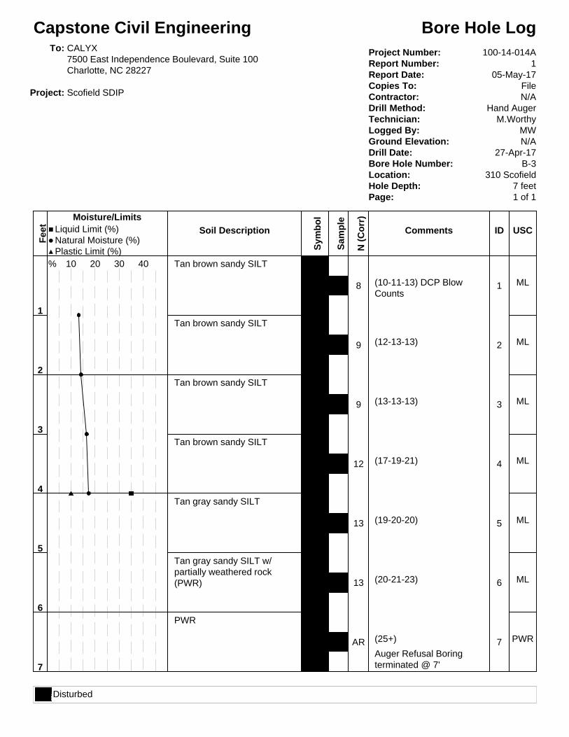
Project Number: 100-14-014AReport Number: 1Report Date: 05-May-17Copies To: FileContractor: N/ADrill Method: Hand AugerTechnician: M.WorthyLogged By: MWGround Elevation: N/ADrill Date: 27-Apr-17Bore Hole Number: B-3Location: 310 ScofieldHole Depth: 7 feetPage: 1 of 1
Disturbed
Fee
t
1
2
3
4
5
6
7
Moisture/Limits
% 10 20 30 40Plastic Limit (%)Natural Moisture (%)Liquid Limit (%) Soil Description
Tan brown sandy SILT
Tan brown sandy SILT
Tan brown sandy SILT
Tan brown sandy SILT
Tan gray sandy SILT
Tan gray sandy SILT w/partially weathered rock(PWR)
PWR
Sym
bo
l
Sam
ple
N (
Co
rr)
8
9
9
12
13
13
AR
Comments
(10-11-13) DCP BlowCounts
(12-13-13)
(13-13-13)
(17-19-21)
(19-20-20)
(20-21-23)
(25+)
Auger Refusal Boringterminated @ 7'
ID
1
2
3
4
5
6
7
USC
ML
ML
ML
ML
ML
ML
PWR

1
Project Name: 4/30/17
Project Number: Charlotte, NC
Capstone Project Number: -
Architect/Engineer:
Liquid Limit Plasticity Index
B-1 1.0 Soil 17.8
B-1 2.0 Soil 18.5
B-1 3.0 Soil 19.5
B-1 4.0 Soil 16.9 59.2 CL 30 20 10
B-2 1.0 Soil 19.8
B-2 2.0 Soil 20.4
B-2 3.0 Soil 22.4
B-2 4.0 Soil 23.8
B-3 1.0 Soil 13.2
B-3 2.0 Soil 14.2
B-3 3.0 Soil 16.5
B-3 4.0 Soil 17.3 60.1 ML 35 25 10
Laboratory Test Results Summary
2020 N. Tryon Street
Charlotte, NC 28206
980.938.6770 - Tel
Maximum
Dry
Density
(pcf)
Optimum
Moisture
(%)
Page:
Passing
No. 200
Sieve (%)
Scofiled SDIP
Comments:
Date:
Project Location:
100-14-014A
CALYX M. WorthyTechnician:
USCS
Classification
Natural
Moisture
Content
(%)
-
Contractor:
Boring or
Sample
No.
Sample
Depth
(feet)
ATTERBERG LIMITS
Plastic Limit
Sample
Type

I. Drilling and Sampling Symbols:
SS - Split Spoon Sampler RB - Rock Bit Drilling
ST - Shelby Tube Sampler BS - Bulk Sample of Cuttings
RC - Rock Core: NX, BX, AX PA - Power Auger (no sample)
PM - Pressuremeter HAS - Hollow Stem Auger
DC - Dutch Cone Penetrometer WS - Wash Sample
WHO - Weight of Hammer
Standard Penetration (Blows/Ft) refers to the blows per foot of a 140 lb. hammer falling 30 inches on
a 2 inch O.D. split spoon sampler in ASTM D-1586. The blow count is commonly referred to as the
N-value.
II. Correlation of Penetration Resistances to Soil Properties:
Relative Density-Sands, Silts
SPT-N Relative Density N-Values Consistency of Cohesive Soils
0-4 Very Loose 0-2 Very Soft
5-10 Loose 3-4 Soft
11-30 Medium Dense 5-8 Firm
31-50 Dense 9-15 Stiff
50 or more Very Dense 16-30 Very Stiff
31-50 Hard
51 or more Very Hard
III. Unified Soil Classification Symbols:
CP - Poorly Graded Gravel ML - Low Plasticity Silts
GW - Well Graded Gravel MH - High Plasticity Silts
GM - Dirty Gravel CL - Low Plasticity Clays
GC - Clayey Gravels CH - High Plasticity Clays
SP - Poorly Graded Sands OL - Low Plasticity Organics
SW - Well Graded Sands OH - High Plasticity Organics
SM - Silty Sands CL-ML - Dual Classification
SC - Clayey Sands (Typical)
IV. Water Level Measurement Symbols:
WL - Water Level BCR - Before Casing Removal
WS - While Sampling ACR - After Casing Removal
WD - While Drilling WCI - With Casing Installed
The water levels are those water levels actually measured in the borehole at the times indicated by the
symbol. The measurements are relatively reliable when auguring, without adding fluids, in a granular soil.
In clays and plastic silt, the accurate determination of water levels may require several days for the water
level to stabilize. In such cases, additional methods of measurement are generally applied.
The elevations indicated on the boring logs should be considered approximate and were not determined
using accepted surveying techniques.
Reference Notes for Boring Logs

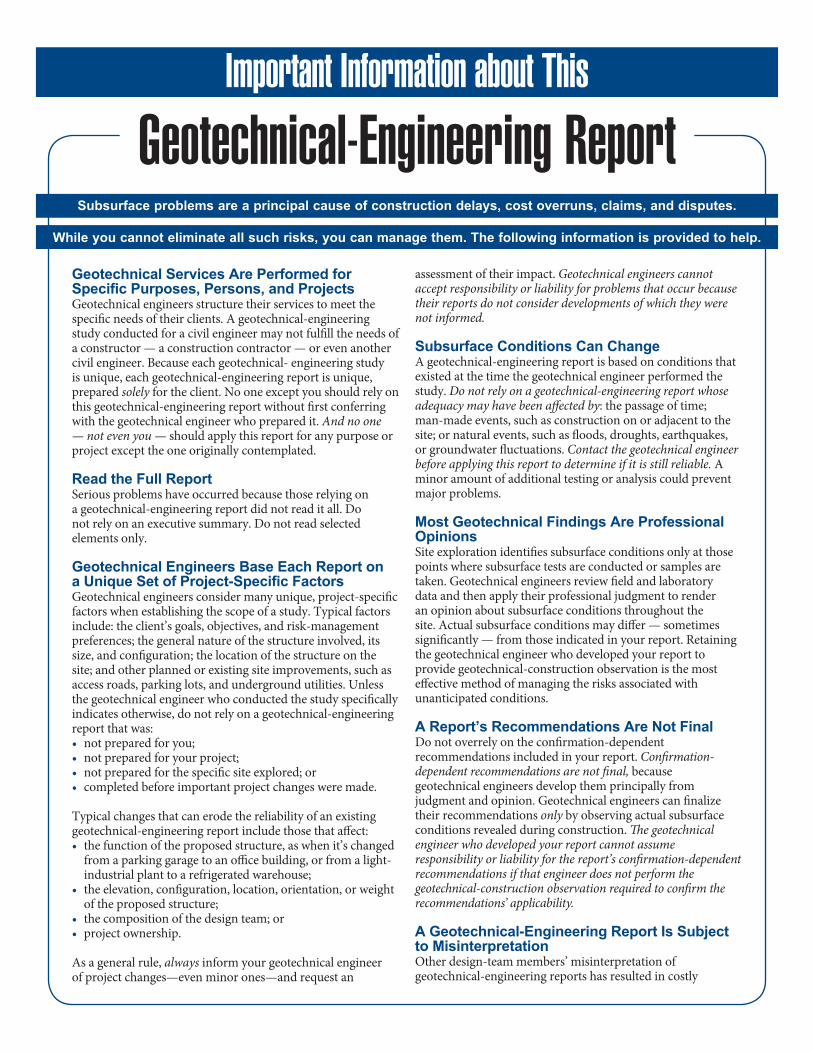
Geotechnical-Engineering Report
Geotechnical Services Are Performed for Specific Purposes, Persons, and ProjectsGeotechnical engineers structure their services to meet the specific needs of their clients. A geotechnical-engineering study conducted for a civil engineer may not fulfill the needs of a constructor — a construction contractor — or even another civil engineer. Because each geotechnical- engineering study is unique, each geotechnical-engineering report is unique, prepared solely for the client. No one except you should rely on this geotechnical-engineering report without first conferring with the geotechnical engineer who prepared it. And no one — not even you — should apply this report for any purpose or project except the one originally contemplated.
Read the Full ReportSerious problems have occurred because those relying on a geotechnical-engineering report did not read it all. Do not rely on an executive summary. Do not read selected elements only.
Geotechnical Engineers Base Each Report on a Unique Set of Project-Specific FactorsGeotechnical engineers consider many unique, project-specific factors when establishing the scope of a study. Typical factors include: the client’s goals, objectives, and risk-management preferences; the general nature of the structure involved, its size, and configuration; the location of the structure on the site; and other planned or existing site improvements, such as access roads, parking lots, and underground utilities. Unless the geotechnical engineer who conducted the study specifically indicates otherwise, do not rely on a geotechnical-engineering report that was:• not prepared for you;• not prepared for your project;• not prepared for the specific site explored; or• completed before important project changes were made.
Typical changes that can erode the reliability of an existing geotechnical-engineering report include those that affect: • the function of the proposed structure, as when it’s changed
from a parking garage to an office building, or from a light-industrial plant to a refrigerated warehouse;
• the elevation, configuration, location, orientation, or weight of the proposed structure;
• the composition of the design team; or• project ownership.
As a general rule, always inform your geotechnical engineer of project changes—even minor ones—and request an
assessment of their impact. Geotechnical engineers cannot accept responsibility or liability for problems that occur because their reports do not consider developments of which they were not informed.
Subsurface Conditions Can ChangeA geotechnical-engineering report is based on conditions that existed at the time the geotechnical engineer performed the study. Do not rely on a geotechnical-engineering report whose adequacy may have been affected by: the passage of time; man-made events, such as construction on or adjacent to the site; or natural events, such as floods, droughts, earthquakes, or groundwater fluctuations. Contact the geotechnical engineer before applying this report to determine if it is still reliable. A minor amount of additional testing or analysis could prevent major problems.
Most Geotechnical Findings Are Professional OpinionsSite exploration identifies subsurface conditions only at those points where subsurface tests are conducted or samples are taken. Geotechnical engineers review field and laboratory data and then apply their professional judgment to render an opinion about subsurface conditions throughout the site. Actual subsurface conditions may differ — sometimes significantly — from those indicated in your report. Retaining the geotechnical engineer who developed your report to provide geotechnical-construction observation is the most effective method of managing the risks associated with unanticipated conditions.
A Report’s Recommendations Are Not FinalDo not overrely on the confirmation-dependent recommendations included in your report. Confirmation-dependent recommendations are not final, because geotechnical engineers develop them principally from judgment and opinion. Geotechnical engineers can finalize their recommendations only by observing actual subsurface conditions revealed during construction. The geotechnical engineer who developed your report cannot assume responsibility or liability for the report’s confirmation-dependent recommendations if that engineer does not perform the geotechnical-construction observation required to confirm the recommendations’ applicability.
A Geotechnical-Engineering Report Is Subject to MisinterpretationOther design-team members’ misinterpretation of geotechnical-engineering reports has resulted in costly
Important Information about This
Subsurface problems are a principal cause of construction delays, cost overruns, claims, and disputes.
While you cannot eliminate all such risks, you can manage them. The following information is provided to help.
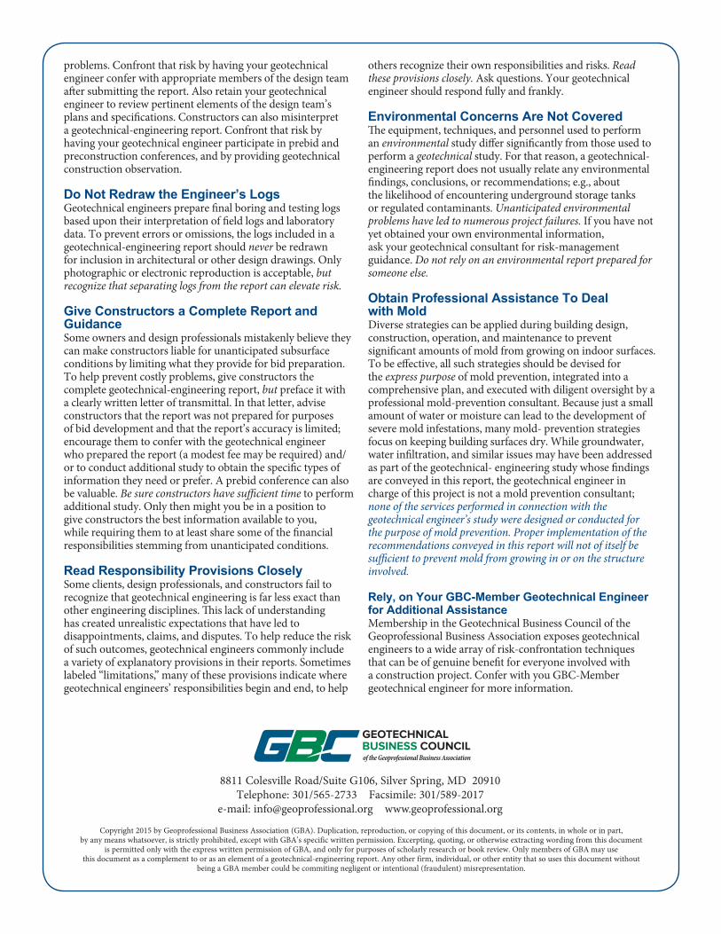
problems. Confront that risk by having your geo technical engineer confer with appropriate members of the design team after submitting the report. Also retain your geotechnical engineer to review pertinent elements of the design team’s plans and specifications. Constructors can also misinterpret a geotechnical-engineering report. Confront that risk by having your geotechnical engineer participate in prebid and preconstruction conferences, and by providing geotechnical construction observation.
Do Not Redraw the Engineer’s LogsGeotechnical engineers prepare final boring and testing logs based upon their interpretation of field logs and laboratory data. To prevent errors or omissions, the logs included in a geotechnical-engineering report should never be redrawn for inclusion in architectural or other design drawings. Only photographic or electronic reproduction is acceptable, but recognize that separating logs from the report can elevate risk.
Give Constructors a Complete Report and GuidanceSome owners and design professionals mistakenly believe they can make constructors liable for unanticipated subsurface conditions by limiting what they provide for bid preparation. To help prevent costly problems, give constructors the complete geotechnical-engineering report, but preface it with a clearly written letter of transmittal. In that letter, advise constructors that the report was not prepared for purposes of bid development and that the report’s accuracy is limited; encourage them to confer with the geotechnical engineer who prepared the report (a modest fee may be required) and/or to conduct additional study to obtain the specific types of information they need or prefer. A prebid conference can also be valuable. Be sure constructors have sufficient time to perform additional study. Only then might you be in a position to give constructors the best information available to you, while requiring them to at least share some of the financial responsibilities stemming from unanticipated conditions.
Read Responsibility Provisions CloselySome clients, design professionals, and constructors fail to recognize that geotechnical engineering is far less exact than other engineering disciplines. This lack of understanding has created unrealistic expectations that have led to disappointments, claims, and disputes. To help reduce the risk of such outcomes, geotechnical engineers commonly include a variety of explanatory provisions in their reports. Sometimes labeled “limitations,” many of these provisions indicate where geotechnical engineers’ responsibilities begin and end, to help
others recognize their own responsibilities and risks. Read these provisions closely. Ask questions. Your geotechnical engineer should respond fully and frankly.
Environmental Concerns Are Not Covered The equipment, techniques, and personnel used to perform an environmental study differ significantly from those used to perform a geotechnical study. For that reason, a geotechnical-engineering report does not usually relate any environmental findings, conclusions, or recommendations; e.g., about the likelihood of encountering underground storage tanks or regulated contaminants. Unanticipated environmental problems have led to numerous project failures. If you have not yet obtained your own environmental information, ask your geotechnical consultant for risk-management guidance. Do not rely on an environmental report prepared for someone else.
Obtain Professional Assistance To Deal with MoldDiverse strategies can be applied during building design, construction, operation, and maintenance to prevent significant amounts of mold from growing on indoor surfaces. To be effective, all such strategies should be devised for the express purpose of mold prevention, integrated into a comprehensive plan, and executed with diligent oversight by a professional mold-prevention consultant. Because just a small amount of water or moisture can lead to the development of severe mold infestations, many mold- prevention strategies focus on keeping building surfaces dry. While groundwater, water infiltration, and similar issues may have been addressed as part of the geotechnical- engineering study whose findings are conveyed in this report, the geotechnical engineer in charge of this project is not a mold prevention consultant; none of the services performed in connection with the geotechnical engineer’s study were designed or conducted for the purpose of mold prevention. Proper implementation of the recommendations conveyed in this report will not of itself be sufficient to prevent mold from growing in or on the structure involved.
Rely, on Your GBC-Member Geotechnical Engineer for Additional AssistanceMembership in the Geotechnical Business Council of the Geoprofessional Business Association exposes geotechnical engineers to a wide array of risk-confrontation techniques that can be of genuine benefit for everyone involved with a construction project. Confer with you GBC-Member geotechnical engineer for more information.
8811 Colesville Road/Suite G106, Silver Spring, MD 20910Telephone: 301/565-2733 Facsimile: 301/589-2017
e-mail: [email protected] www.geoprofessional.org
Copyright 2015 by Geoprofessional Business Association (GBA). Duplication, reproduction, or copying of this document, or its contents, in whole or in part, by any means whatsoever, is strictly prohibited, except with GBA’s specific written permission. Excerpting, quoting, or otherwise extracting wording from this document
is permitted only with the express written permission of GBA, and only for purposes of scholarly research or book review. Only members of GBA may use this document as a complement to or as an element of a geotechnical-engineering report. Any other firm, individual, or other entity that so uses this document without
being a GBA member could be commiting negligent or intentional (fraudulent) misrepresentation.


