+ All Categories
Home > Documents > Reports NTPC

Reports NTPC

Date post: 07-Apr-2018
Category:
Upload: ashish-agarwal
View: 227 times
Download: 0 times
Share this document with a friend
53
1 CHAPTER 1 INTRODUCTION National Thermal Power Corporation Ltd. (NTPC) was incorporated in  1975 by an Act of parliament, to supplement the efforts of the states for quicker and greater capacity addition in thermal power generation. In  1997 , the Department of Public Enterprises, Government of India granted ‘Navratna’ (Nine Jewels) status with powers of operational autonomy to the board of NTPC with an objective to turn the public sector enterprise into a global giant. This has helped NTPC in speedy implementation of power projects, adoption of new technologies and formation of Joint Ventures in the core generation as well as service businesses. Recently, NTPC has been awarded the  Maharatna status which has given it greater autonomy. In line with its vision and mission over the last thirty five y ears NTPC has grown to become the largest power utility in India with a commissioned generation capacity of  34,754  MW (as on July, 2011) with power stations spread over the length and breadth of the country, covering portfolios in coal based and combined cycle power plants. Besides, being Indias largest power generation utility, NTPC has also grown to become the number one independent power producer in Asia and second globally in 2009 (by Platts, a division of McGraw-Hill companies), 5 th largest company in Asia and 317 th Largest company in the world (FORBES ranking   2009) with Net Sales of Rs. 53721 crore during 2010-11 as against Rs.46169 crore during 2009-10, as increase of 16.36% as on 31.03.2011. NTPC has also the honor of becoming the 6 th largest thermal power generator in the world and second most efficient in terms of capacity utilization amongst top 10 utilities in the world.
Transcript

8/3/2019 Reports NTPC

http://slidepdf.com/reader/full/reports-ntpc 1/53

CHAPTER 1

INTRODUCTION

National Thermal Power Corporation Ltd. (NTPC) was incorporated in 1975 by an Act

of parliament, to supplement the efforts of the states for quicker and greater capacity addition

in thermal power generation. In 1997 , the Department of Public Enterprises, Government of 

India granted ‘Navratna’  (Nine Jewels) status with powers of operational autonomy to the

board of NTPC with an objective to turn the public sector enterprise into a global giant. This

has helped NTPC in speedy implementation of power projects, adoption of new technologies

and formation of Joint Ventures in the core generation as well as service businesses. Recently,

NTPC has been awarded the „ Maharatna’ status which has given it greater autonomy.

In line with its vision and mission over the last thirty five years NTPC has grown to

become the largest power utility in India with a commissioned generation capacity of  34,754

 MW (as on July, 2011) with power stations spread over the length and breadth of the country,

covering portfolios in coal based and combined cycle power plants.

Besides, being India‟s largest power generation utility, NTPC has also grown to

become the number one independent power producer in Asia and second globally in 2009 (by

Platts, a division of McGraw-Hill companies), 5th largest company in Asia and 317th Largest

company in the world (FORBES ranking  –  2009) with Net Sales of Rs. 53721 crore during

2010-11 as against Rs.46169 crore during 2009-10, as increase of 16.36% as on 31.03.2011.

NTPC has also the honor of becoming the 6th

largest thermal power generator in the world and

second most efficient in terms of capacity utilization amongst top 10 utilities in the world.

8/3/2019 Reports NTPC

http://slidepdf.com/reader/full/reports-ntpc 2/53

In line with the changing business environment, NTPC has expanded its operations in

the area of Hydro Power and covered substantial ground in the areas of Coal Mining, Oil &

Gas Value Chain, Power Trading and Distribution. With these forward and backward

integration plans, NTPC has been re-christened as “NTPC Limited” since 7th

Nov, 2005.

Today NTPC is more than a company. It is an institution, which has moulded the

economy of India setting many landmarks particularly in Power Plant Engineering, Operation

and Maintenance, Contract Management that other power organizations would strive to

emulate. NTPC accepted the challenging task of taking over and running of the Ratnagiri Gas

& Power Station (erstwhile Dabhol Power Plant). NTPC has drawn an ambitious programme

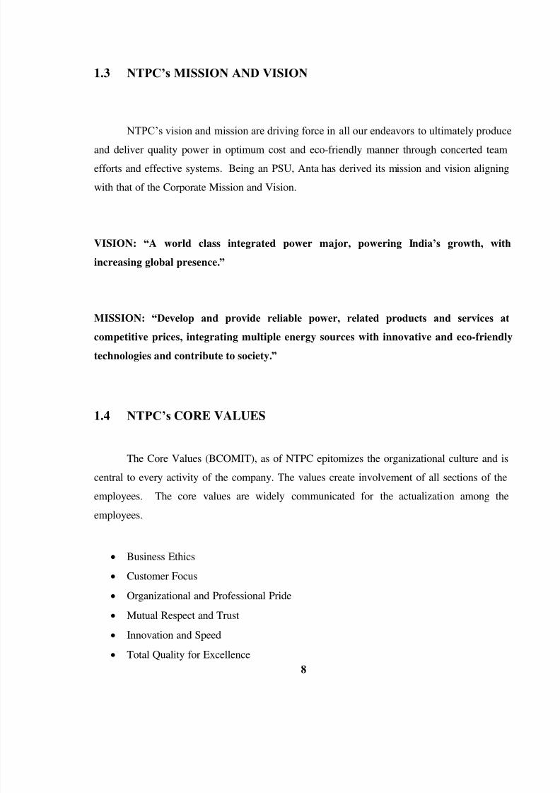
to become a 56000 plus MW Company by 2012 and 75000 plus MW Company by 2017.

With a share of 17.75% in the total installed capacity in the country, NTPC‟s market share in

the country‟s power generation was 27.4% during FY 2010-11.

8/3/2019 Reports NTPC

http://slidepdf.com/reader/full/reports-ntpc 3/53

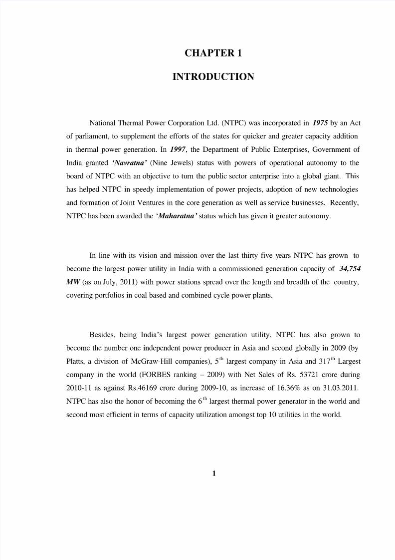
Figure 1.1 Map Showing All NTPC Plants

8/3/2019 Reports NTPC

http://slidepdf.com/reader/full/reports-ntpc 4/53

1.1 LOCATION OF NTPC PLANTS WITH INSTALLED CAPACITY

NTPC is having a number of Coal Fired Stations as well as Gas Fired Stationsthroughout the Country. Some of the Plants are constructed and run by NTPC in Joint Ventures

with other organizations. 

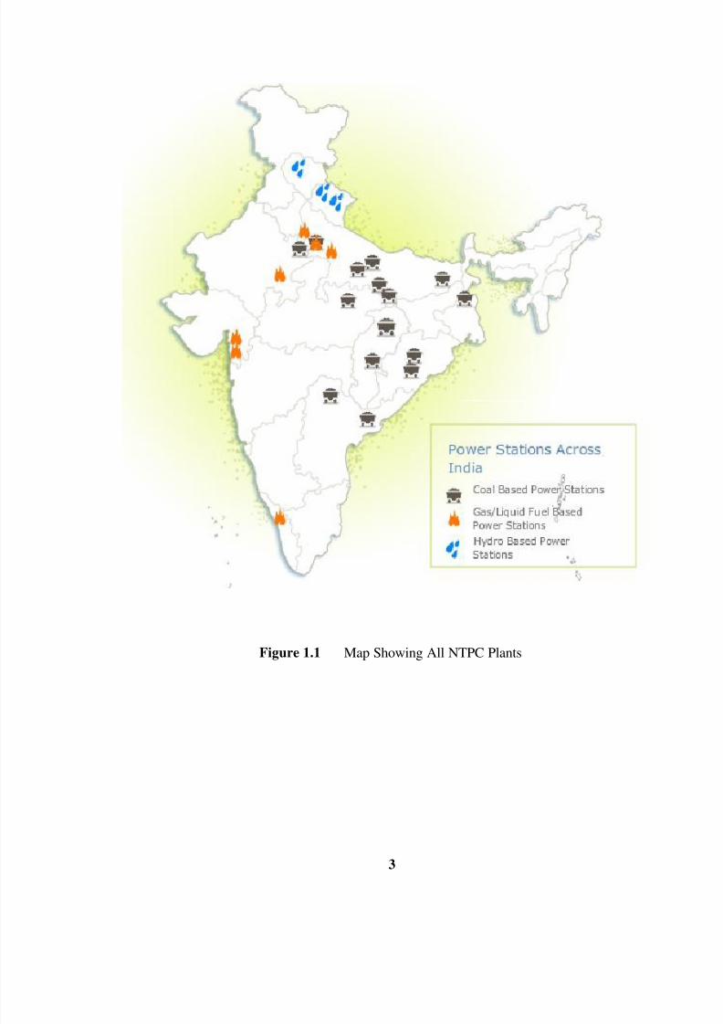
1.1.1  COAL STATIONS (OWNED BY NTPC)

Figure 1.2 Coal Fired Stations owned by NTPC 

8/3/2019 Reports NTPC

http://slidepdf.com/reader/full/reports-ntpc 5/53

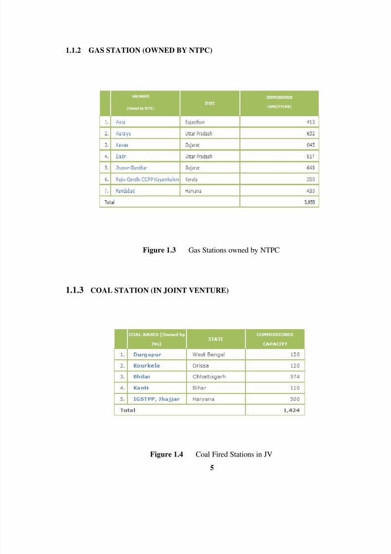
1.1.2  GAS STATION (OWNED BY NTPC)

Figure 1.3 Gas Stations owned by NTPC 

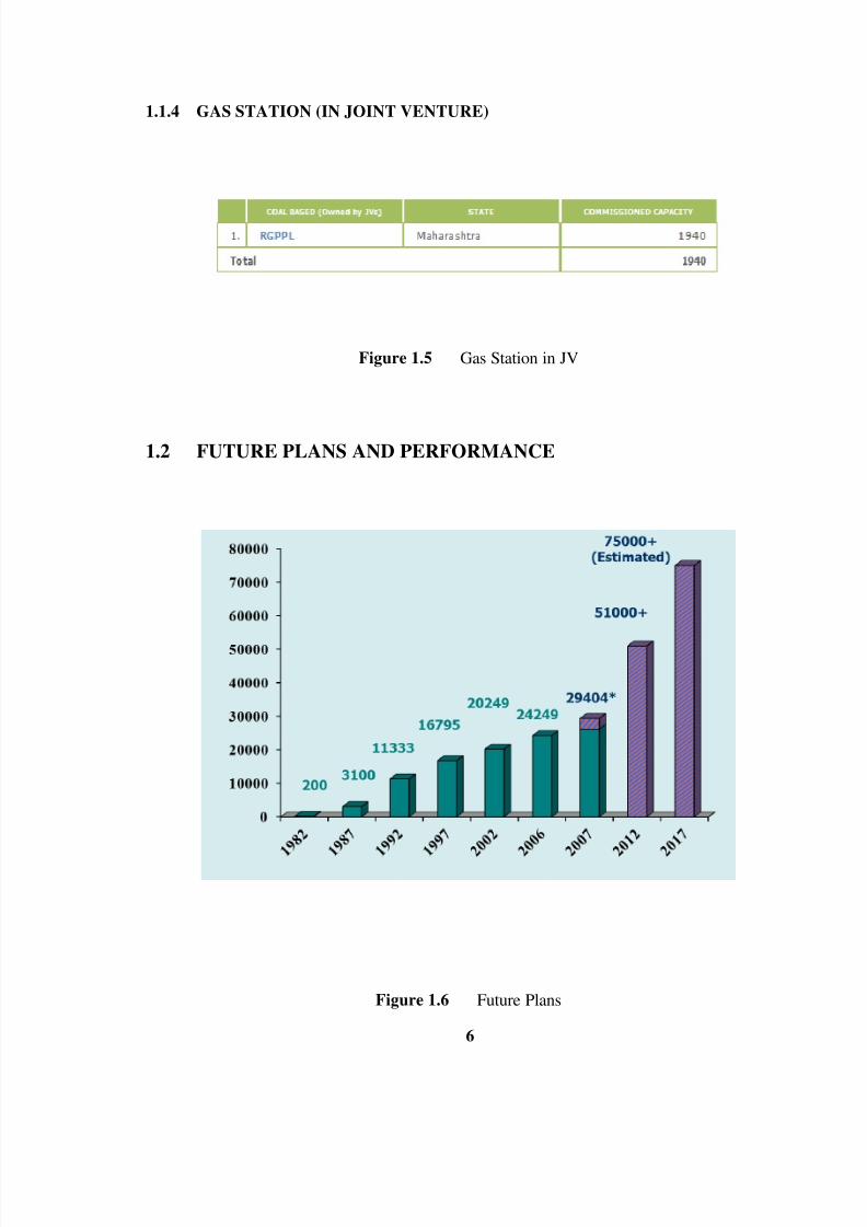
1.1.3  COAL STATION (IN JOINT VENTURE) 

Figure 1.4 Coal Fired Stations in JV 

8/3/2019 Reports NTPC

http://slidepdf.com/reader/full/reports-ntpc 6/53

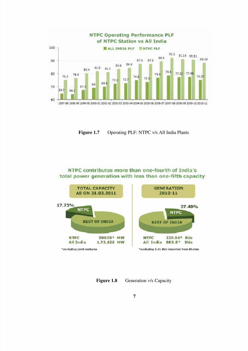
1.1.4  GAS STATION (IN JOINT VENTURE)

Figure 1.5  Gas Station in JV 

1.2 FUTURE PLANS AND PERFORMANCE

Figure 1.6 Future Plans 

8/3/2019 Reports NTPC

http://slidepdf.com/reader/full/reports-ntpc 7/53

Figure 1.7 Operating PLF: NTPC v/s All India Plants

Figure 1.8 Generation v/s Capacity 

8/3/2019 Reports NTPC

http://slidepdf.com/reader/full/reports-ntpc 8/53

1.3 NTPC’s MISSION AND VISION 

 NTPC‟s vision and mission are driving force in all our endeavors to ultimately produce

and deliver quality power in optimum cost and eco-friendly manner through concerted team

efforts and effective systems. Being an PSU, Anta has derived its mission and vision aligning

with that of the Corporate Mission and Vision.

VISION: “A world class integrated power major, powering India’s growth, with

increasing global presence.” 

MISSION: “Develop and provide reliable power, related products and services at

competitive prices, integrating multiple energy sources with innovative and eco-friendly

technologies and contribute to society.” 

1.4 NTPC’s CORE VALUES

The Core Values (BCOMIT), as of NTPC epitomizes the organizational culture and is

central to every activity of the company. The values create involvement of all sections of the

employees. The core values are widely communicated for the actualization among the

employees. 

  Business Ethics

  Customer Focus

  Organizational and Professional Pride

  Mutual Respect and Trust

  Innovation and Speed

  Total Quality for Excellence

8/3/2019 Reports NTPC

http://slidepdf.com/reader/full/reports-ntpc 9/53

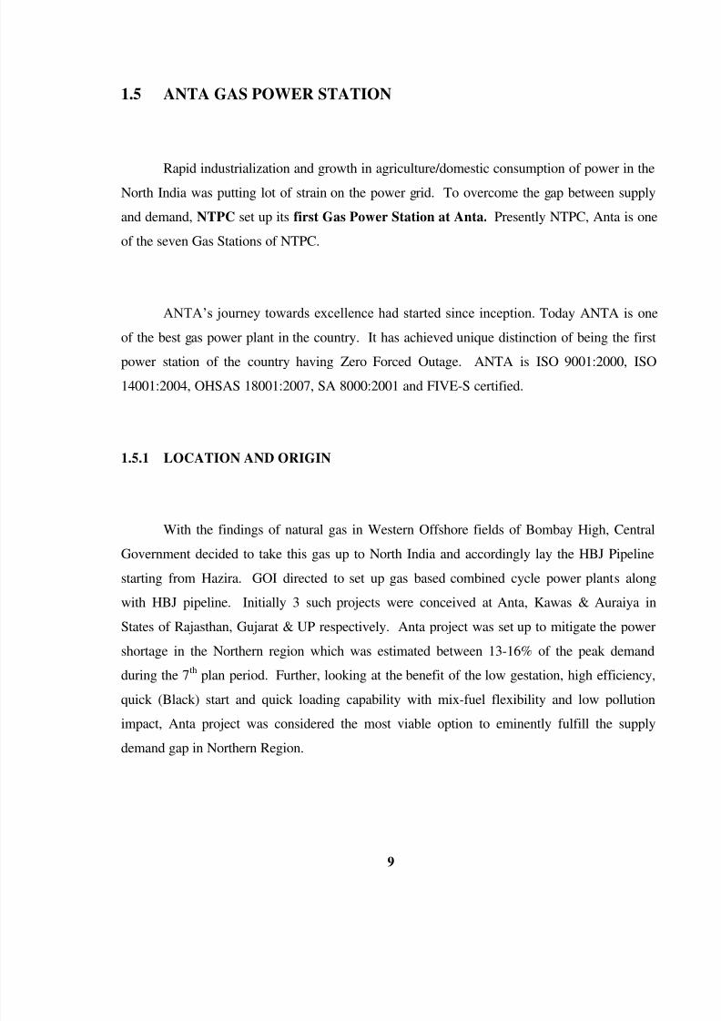
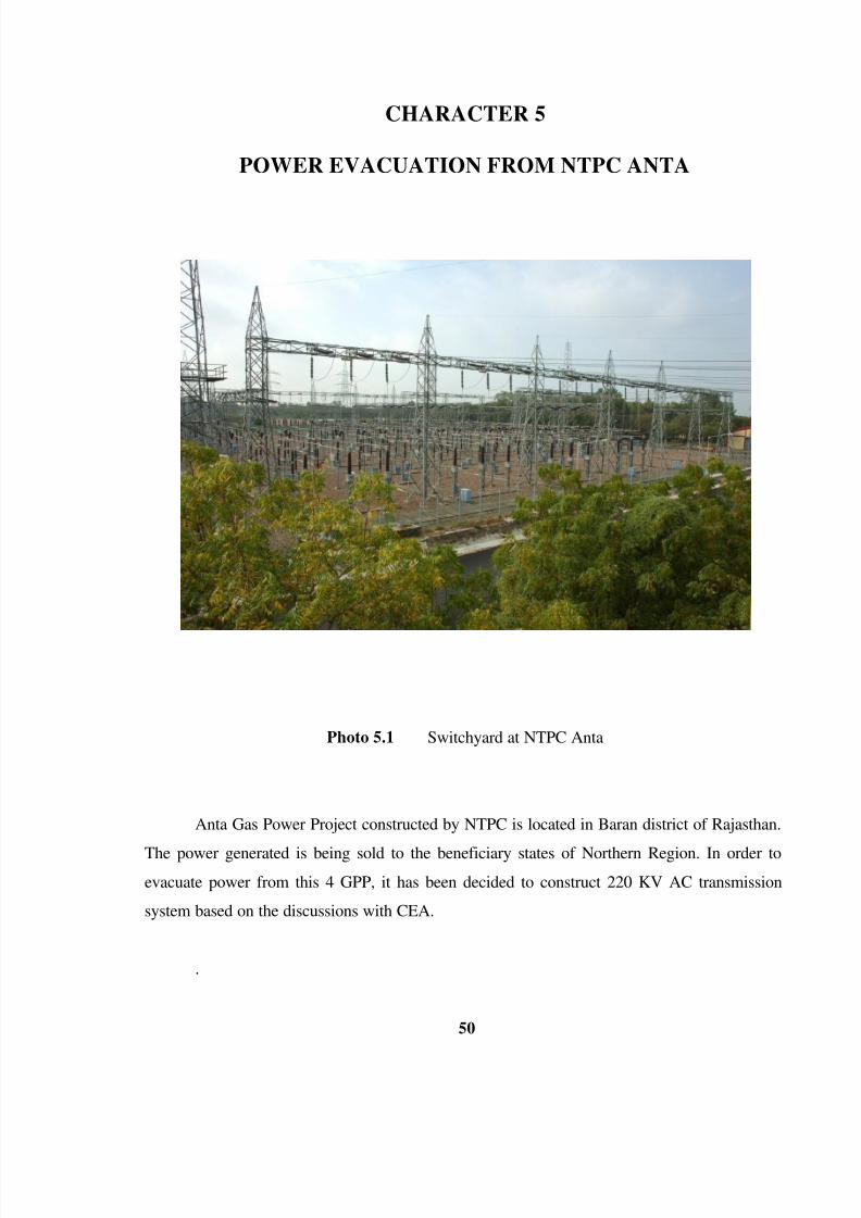
1.5 ANTA GAS POWER STATION

Rapid industrialization and growth in agriculture/domestic consumption of power in the

North India was putting lot of strain on the power grid. To overcome the gap between supply

and demand, NTPC set up its first Gas Power Station at Anta. Presently NTPC, Anta is one

of the seven Gas Stations of NTPC.

ANTA‟s journey towards excellence had started since inception. Today ANTA is one

of the best gas power plant in the country. It has achieved unique distinction of being the first

power station of the country having Zero Forced Outage. ANTA is ISO 9001:2000, ISO

14001:2004, OHSAS 18001:2007, SA 8000:2001 and FIVE-S certified.

1.5.1 LOCATION AND ORIGIN

With the findings of natural gas in Western Offshore fields of Bombay High, CentralGovernment decided to take this gas up to North India and accordingly lay the HBJ Pipeline

starting from Hazira. GOI directed to set up gas based combined cycle power plants along

with HBJ pipeline. Initially 3 such projects were conceived at Anta, Kawas & Auraiya in

States of Rajasthan, Gujarat & UP respectively. Anta project was set up to mitigate the power

shortage in the Northern region which was estimated between 13-16% of the peak demand

during the 7th

plan period. Further, looking at the benefit of the low gestation, high efficiency,

quick (Black) start and quick loading capability with mix-fuel flexibility and low pollution

impact, Anta project was considered the most viable option to eminently fulfill the supply

demand gap in Northern Region. 

8/3/2019 Reports NTPC

http://slidepdf.com/reader/full/reports-ntpc 10/53

10 

Figure 1.9 Location of NTPC, Anta 

1.5.2 BREIF PROFILE OF NTPC ANTA

  Station : Combined Cycle Gas Based Power Station

  Gas Turbines: 3 x 88.71 MW

  Steam Turbine: 1 x 153.2 MW

  Total Capacity : 419.33 MW

 Commercial Operation started w.e.f. 01.08.1990.


8/3/2019 Reports NTPC

http://slidepdf.com/reader/full/reports-ntpc 11/53

11 

1.5.3 SALIENT FEATURES OF NTPC ANTA

Figure 1.10 Salient features of NTPC Anta

8/3/2019 Reports NTPC

http://slidepdf.com/reader/full/reports-ntpc 12/53

12 

1.6 PRODUCTS, SERVICES AND DELIVERY MECHANISM

Sole product of NTPC-Anta is electrical power generated by using gas or naphtha as a

main fuel. The generated power is transmitted through six 220 KV Lines. Thus NTPC‟s role is

limited up to Switchyard, beyond which PGCIL network feeds to respective DISCOMs.

Its customer consists of state distribution companies in member states of northern grid

viz. Rajasthan, UP, Delhi, Punjab, Haryana, Himachal Pradesh, Uttaranchal, J&K and

Chandigarh. The coordination for generation scheduling is done by Anta with the NRLDC

(Northern Region Load Dispatch Centre) of Power Grid located at New Delhi. Anta not only

fulfils the customer requirements of adequate and reliable power at competitive price but also

works with the customer to maintain grid stability in the larger interest of the region. To

maintain the grid stability, the supply and demand are to be consistently matched for which, the

communication between the personnel manning the control room at Anta and the NRLDC is

established on continuous basis.

Figure 1.11 Allocation of Different States in Anta‟s Power  

8/3/2019 Reports NTPC

http://slidepdf.com/reader/full/reports-ntpc 13/53

13 

1.7 ORGANIZATIONAL HIERARCHY

 NTPC‟s current 3-tier structure comprises Corporate Centre (CMD, Board of Directors

and Corporate functions), Regional Head Quarters (five in numbers  – NCR, NR, SR, ER and

WR) and Stations/Projects, Anta being one of the stations. Anta falls under NCR-HQ. The

business unit head of ANTA is the GENERAL MANAGER (GM). The power generation is

handled by Operations and Maintenance Department headed by AGM (O&M), reporting to

GM. O&M consists of different sections viz. Operations, Mechanical Maintenance, Electrical

Maintenance, C&I Maintenance, Chemistry, EEMG, MTP, each sub section is headed by a

DGM/Senior Manager. The support function departments viz. F&A, HR, Contracts &

Materials, Safety, TQM, IT etc, headed by DGM/Senior Managers, are directly reporting to theGeneral Manager.

Figure 1.12 Organization Chart of NTPC Anta

8/3/2019 Reports NTPC

http://slidepdf.com/reader/full/reports-ntpc 14/53

14 

1.8 CORPORATE SOCIAL RESPONSIBILITY 

Anta is involved in many CSR activities like rural health check up camps, rural sports,

school furnishing, vocational trainings etc. Anta employees and their family members are

involved in various activities of CSR like voluntary services for education of villagers, help in

emergency situations, eye camps, family planning camps etc.

Photo 1.1 Night View of NTPC, Anta

8/3/2019 Reports NTPC

http://slidepdf.com/reader/full/reports-ntpc 15/53

15 

CHAPTER 2

TECHNOLOGY, EQUIPMENT AND FACILITIES

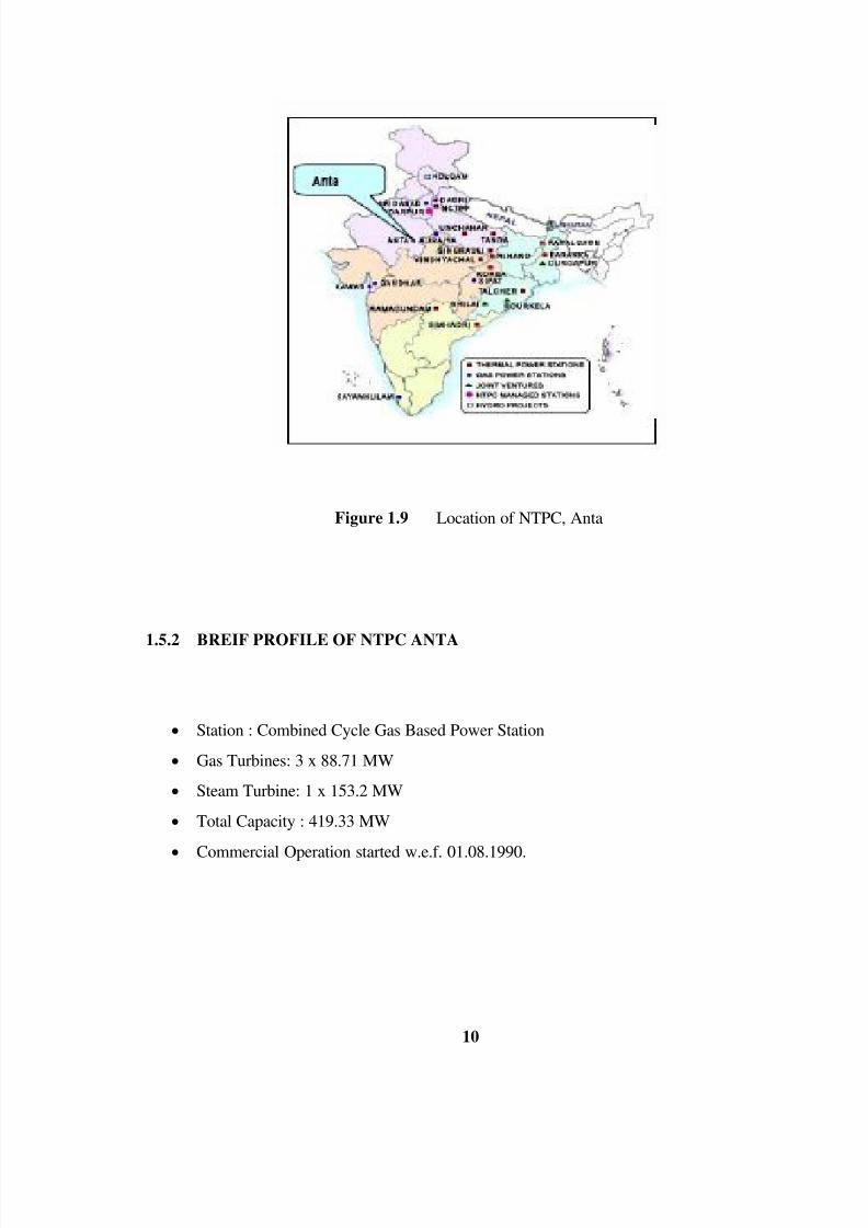
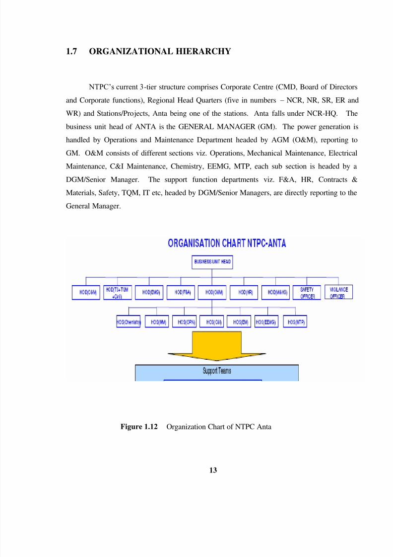
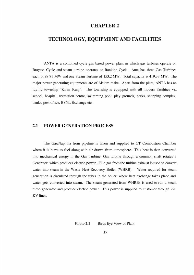
ANTA is a combined cycle gas based power plant in which gas turbines operate on

Brayton Cycle and steam turbine operates on Rankine Cycle. Anta has three Gas Turbines

each of 88.71 MW and one Steam Turbine of 153.2 MW. Total capacity is 419.33 MW. The

major power generating equipments are of Alstom make. Apart from the plant, ANTA has an

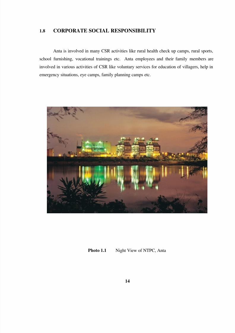
idyllic township “Kiran Kunj”. The township is equipped with all modern facilities viz.

school, hospital, recreation centre, swimming pool, play grounds, parks, shopping complex,

banks, post office, BSNL Exchange etc.

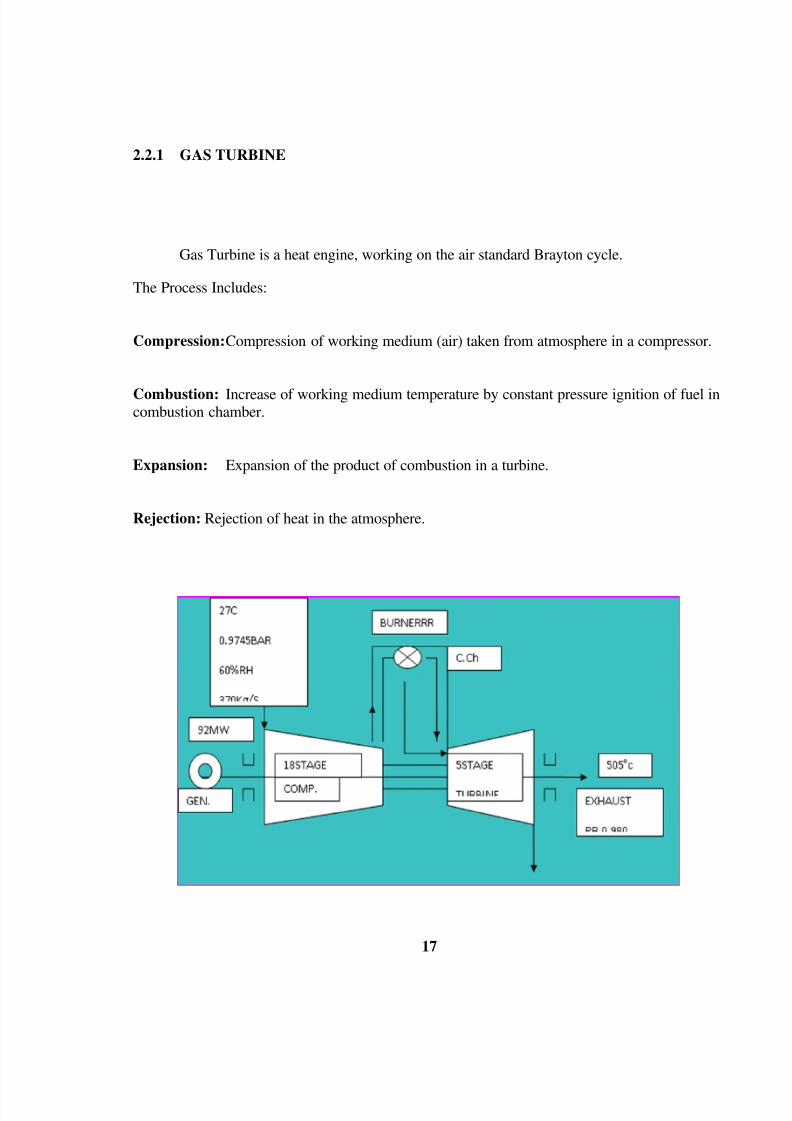
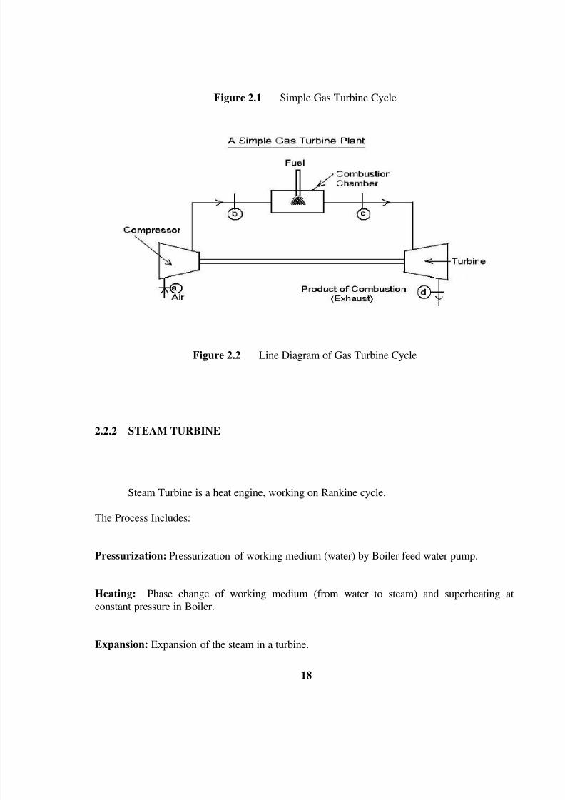
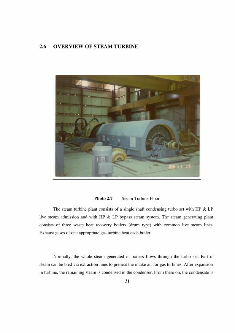
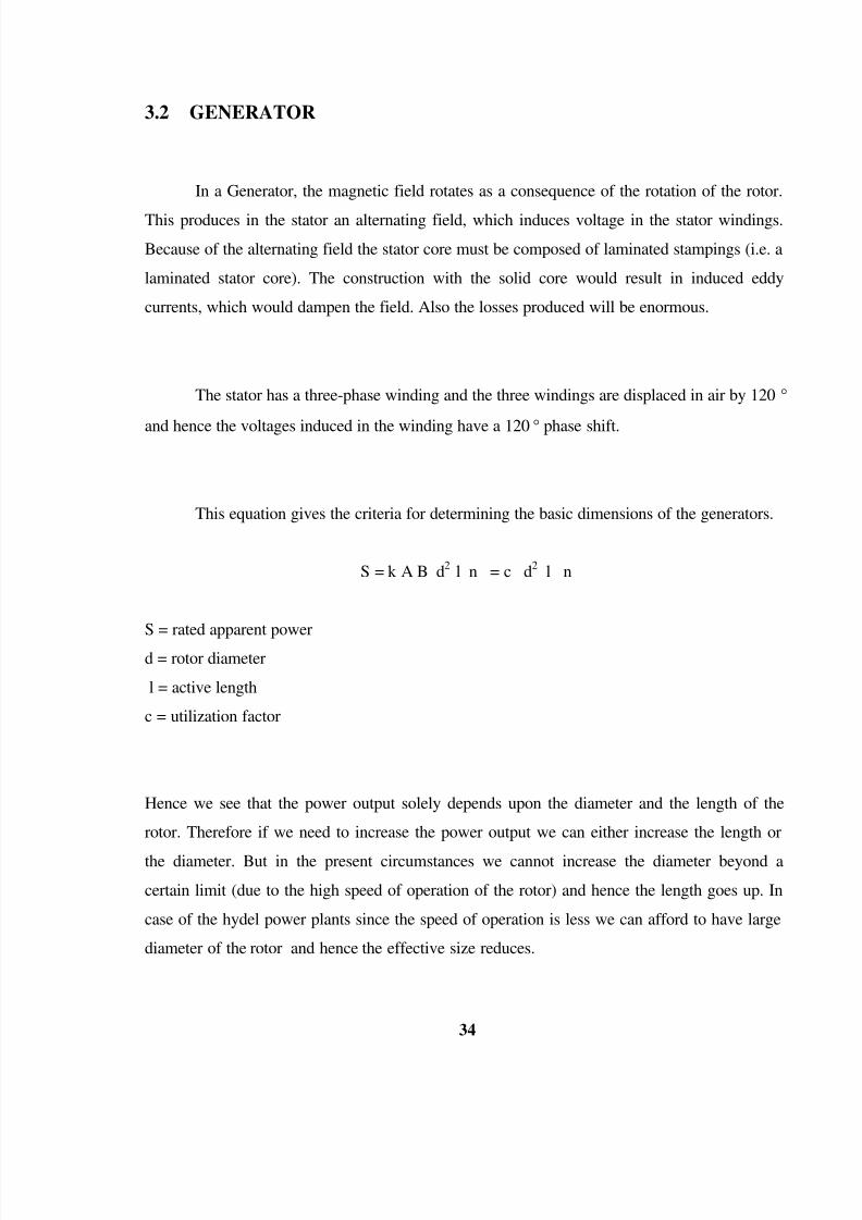
2.1 POWER GENERATION PROCESS

The Gas/Naphtha from pipeline is taken and supplied to GT Combustion Chamberwhere it is burnt as fuel along with air drawn from atmosphere. This heat is then converted

into mechanical energy in the Gas Turbine. Gas turbine through a common shaft rotates a

Generator, which produces electric power. Flue gas from the turbine exhaust is used to convert

water into steam in the Waste Heat Recovery Boiler (WHRB). Water required for steam

generation is circulated through the tubes in the boiler, where heat exchange takes place and

water gets converted into steam. The steam generated from WHRBs is used to run a steam

turbo generator and produce electric power. This power is supplied to customer through 220

KV lines.

Photo 2.1 Birds Eye View of Plant

8/3/2019 Reports NTPC

http://slidepdf.com/reader/full/reports-ntpc 16/53

16 

2.2 OVERVIEW OF COMBINED CYCLE

Combined cycle power plant integrates two power conversion cycles with the principal

objective of increasing overall plant efficiency.

  Bratyon cycle (for gas turbine)

  Rankine cycle (for steam turbine)

Let us have a look on How Combined Cycle works in a combined cycle power plant to

increase the efficiency of power generation process.

  Gas turbine exhaust is at temperature of 500-550 Celcius.

  Steam generation Process for Rankine cycle requires a temperature of 500-550 Celcius

to generate steam.

  Gas turbine exhaust heat can be recovered using a waste heat recovery boiler to

generate steam in a water tube boiler so as to run a steam turbine on Rankine cycle.

  Efficiency of simple gas turbine cycle is 34%.

  The efficiency of Rankine cycle is 35%.

  The overall efficiency of power generation by combined cycle comes to 49%.

8/3/2019 Reports NTPC

http://slidepdf.com/reader/full/reports-ntpc 17/53

17 

2.2.1 GAS TURBINE

Gas Turbine is a heat engine, working on the air standard Brayton cycle.

The Process Includes:

Compression:Compression of working medium (air) taken from atmosphere in a compressor.

Combustion: Increase of working medium temperature by constant pressure ignition of fuel incombustion chamber.

Expansion: Expansion of the product of combustion in a turbine.

Rejection: Rejection of heat in the atmosphere.

8/3/2019 Reports NTPC

http://slidepdf.com/reader/full/reports-ntpc 18/53

18 

Figure 2.1 Simple Gas Turbine Cycle

Figure 2.2 Line Diagram of Gas Turbine Cycle

2.2.2 STEAM TURBINE 

Steam Turbine is a heat engine, working on Rankine cycle.

The Process Includes:

Pressurization: Pressurization of working medium (water) by Boiler feed water pump.

Heating: Phase change of working medium (from water to steam) and superheating at

constant pressure in Boiler.

Expansion: Expansion of the steam in a turbine.

8/3/2019 Reports NTPC

http://slidepdf.com/reader/full/reports-ntpc 19/53

19 

Condensation: Condensation of the steam by cooling water.

2.3 GENERAL DESCRIPTION OF COMBINED CYCLE

The 419.33MW anta combined cycle power plant consists of three gas turbines

generator sets of 88.71 MW each and one steam turbine generator set of 153.20 MW. The gas

turbine are equipped with a dual fuel burner for gaseous fuel (natural) and liquid fuel

(naphtha).the station can be operated in the open cycle mode via their exhaust gas bypass

stacks or as modules together with their waste heat recovery boilers and STG in the combined

cycle mode.

The WHRB‟s is designed as dual pressure boilers with high pressure (HP) and low

pressure (LP) sections and condensate preheating at the tail end. The condensate pumped from

the condenser hot well is degasified in the Deaerator at constant pressure and stored in the feed

water tank. From feed water tank, the boiler feed water is extracted by mean of separate boiler

feed water pumps for the HP and LP system serving the 3 WHRB‟s in common HP and LP

main steam lines the turbojet is composed of a single flow HP turbine and one double flow LP

turbine. The Generator is directly coupled to the shaft of LP cylinder. The exhaust steam of the

STG is condensed in a surface condenser cooled by fresh water of the right main Kota canal in

the once through cycle. During the shut-down of canal, the condenser is cooled via a wet

cooling tower in the closed cycle alternatively.

For start up and shut down as well as trip of STG one common HP and LP steam

bypass station for all 3 modules are provided leading the steam directly into the condenser.

Additional steam charged air presenters are installed in front of the GT-compressor inlet to

preheat the intake air for the gas turbine, improving the heat rate during part load operation.

8/3/2019 Reports NTPC

http://slidepdf.com/reader/full/reports-ntpc 20/53

20 

Photo 2.5 View of WHRB

2.4 OVERVIEW OF GAS TURBINE

A gas turbine plant in its most simple form consists of following main part.

  Air intake system

  Compressor

  Combustion chamber

  Turbine

  Generator

  Gas Fuel system

  Naphtha Fuel System

8/3/2019 Reports NTPC

http://slidepdf.com/reader/full/reports-ntpc 21/53

21 

  Gas turbine plant operation

2.4.1 AIR INTAKE SYSTEM

Air enters the suction of compressor after passing through fine filters. There are 945

filters arranged in three levels. These are self cleaning type filters. Compressed air from the

instrument air compressors passes through diaphragm valves and into the blowpipes. A

pressure pulse is given to the filter elements in the reverse direction (inside to outside) this

impulse of air flow cleans the filters.

  Make : FARR

  Material of filter media : Resin Impregnated Media consisting of synthetic and

Cellulose fibers

  Total no. of filter cartridges : 945

  Initiation of pulse cleaning : 6.4 m bar

  Stop of pulse cleaning cycle : 4.6 m bar

  Compressed air pulse clean : 7 bar

  Time interval b\w two pulses : 30 sec.

  Time of a pulse : 0.1 sec.

8/3/2019 Reports NTPC

http://slidepdf.com/reader/full/reports-ntpc 22/53

22 

Figure 2.3 Air Intake Filters

2.4.2 COMPRESSOR

It is 18 stages with additional inlet guide blade, axial flow, reaction compressor. The

blade of the 18 rotor and 19 fixed rows are made of high tensile ferric chrome steel.

The compressor casing is horizontally split at axis, and is made of spherical graphite

cast iron. This material possesses high tensile strength and good expansion quality. Upper and

lower halves of the compressor casing are provided with robust flanges and are held together

by expansion studs with socket head. The compressor casing has three circular ducts at 4th,

7th, 10th row of fixed blades. These ducts are closed to the outside by four bleed valves. Bleed

valves are kept open up to 2700 rpm, so that certain amount of compressor air can be blown

off. These bleed valves reduces the external power input required running compressor during

start up.

2.4.3 COMBUSTION CHAMBER

In combustion chamber, the air compressed and supplied by compressor is brought to

the required process temperature by combustion of liquid/gas fuel. The single combustion

8/3/2019 Reports NTPC

http://slidepdf.com/reader/full/reports-ntpc 23/53

23 

chamber is fitted with only one dual fuel burner and mounted vertically on the

compressor/turbine assembly.

The combustion chamber is all welded steel plate fabricated. The main parts are jacket

with cover, lower upper combustion chamber bodies, finned segment body, burner and inner

casing. Combustion chamber jacket, which houses the components, is made of heat resistant,

low alloy ferrite steel.

The air from the compressor enter the combustion chamber from below and flow

upward through the annular space between combustion chamber jacket and inner section of the

lower combustion chamber body. Approximately 30% air flow enter the combustion chamber

through eight mixing nozzles provided at the lower body as secondary and approximately30%

air flow enter the combustion chamber through upper body via finned segment row (there are

5row) , the remaining40%flow as primary air for combustion, into the swirl insert and enter the

combustion space with turbulence. After the fuel has ignited these gases are thoroughly mixed

with secondary air from mixing nozzles and brought to the permissible turbine inlet temp.

8/3/2019 Reports NTPC

http://slidepdf.com/reader/full/reports-ntpc 24/53

24 

Figure 2.4 Cross Sectional View of Gas turbine

2.4.4 TURBINE 

Turbine is five stage reaction turbines. Due to high temperature of incoming gases, the

first and second row of rotor and fixed blading are air cooled with air from compressor

discharge. Cooling air passes along several holes made in blades and finally blowing out

through numbers of slits in the trailing /leading edge of the blade. This method of cooling

ensures that blades are thoroughly cooled, thereby avoiding cracks induced by thermal stresses.

These cooled blades are fixed rotor blades which are made of cast and nickel based alloy. The

turbine and compressor casing are bolted together at radial flange with expansion bolts, turbine

casing is made of heat resisting ferrite steel in order to with stand thermal stresses.

8/3/2019 Reports NTPC

http://slidepdf.com/reader/full/reports-ntpc 25/53

25 

2.4.5 GENERATOR

Photo 2.6 Generator Rotor

Figure 2.5 Generator Data‟s 

Generator is three phases, two pole air cooled machine. The generator and turbine are

placed on common and plain concrete foundation, with same center line level for the turbine

and generator rotor.

8/3/2019 Reports NTPC

http://slidepdf.com/reader/full/reports-ntpc 26/53

26 

The mechanical energy generated by turbine is converted to electrical energy by the

generator and appear in the stator winding in the form of current and voltage. This balances

the torque of the gas turbine.

It lead the magnetic flux, and carries the field winding, the generator is self excited.

The power required for the excitation is taken from the generator terminals and fed to the field

winding through the excitation transformer and the thrust-controlled rectifier units.

2.4.6 GAS FUEL SYSTEM

Gas comes from GRS at around 18 bars. Manual isolation valve is to be opened by

operator. Motorized stop relief valve will be opened by GT program when required.

In the gas control block there is an emergency stop valve (ESV). This opens with the

help of power oil pressure against spring force. Whenever turbine trips, the oil is drained

(depressurized) and spring force closes the valve, cutting off gas supply to combustion

chamber.

After the ESV is the gas CV, the opening of this valve controls the amount of fuel

going to the combustion chamber.

8/3/2019 Reports NTPC

http://slidepdf.com/reader/full/reports-ntpc 27/53

27 

2.4.7 NAPHTHA FUEL SYSTEM 

Naphtha comes from naphtha station via the forwarding pumps at around 15bar.

Manual isolation valve outside GT hall is to be opened by the operator. Manual isolation

valves before main fuel oil pump and also to be opened. Motorized valve will be opened by GT

program when FG liquid fuel is selected. Naphtha then passes through duplex filter to the main

fuel oil pump, which raises the press to aproox.80 bar. There is release valve which opens

when firing speed is reached (600rpm).

There is an emergency stop valve similar to one in the gas scheme. Finally there is the

control valve directly coupled with the Naphtha nozzle. A minimum opening of the nozzle is

already pre-set. Once stable flame is formed, the nozzle opening increases with the control

valve opening.

2.4.8 GAS TURBINE PLANT OPERATION 

The compressor sucks in air from the atmosphere through the filters called air intake

filters. The compresses air at approx. 11 bar passes into the combustion chamber where it is

used as primary air for combustion and secondary air for cooling of very hot parts. The gas

turbine generates the necessary power to drive the axial-flow compressor and the generator.

Start-up of the GT is drives with the help of starting equipment which runs the generator as a

motor with speed increasing from 0to 600 rpm. At this speed a pilot flame is ignited in the

combustion chamber, fuel (gas/naphtha) enters and combustion takes place.

The speed increases further both with the help of generator motoring and the

combustion of fuel up to about 2000 rpm. At this speed starting equipment is switched off and

only the generator is made ready for synchronization with the grid. After synchronizations, the

8/3/2019 Reports NTPC

http://slidepdf.com/reader/full/reports-ntpc 28/53

28 

turbine load increases up to base load with more and more fuel entering the combustion

chamber.

The hot gases after combustion enter the gas turbine at about 1005 degree centigrade (at

base load). The higher pressure and temperature gas pass through the turbine rotating it and

generator, this produces the electrical power.

The exhaust gas coming out of the GT is at about 500 degree centigrade, this can be

utilized to produce steam in WHRB.

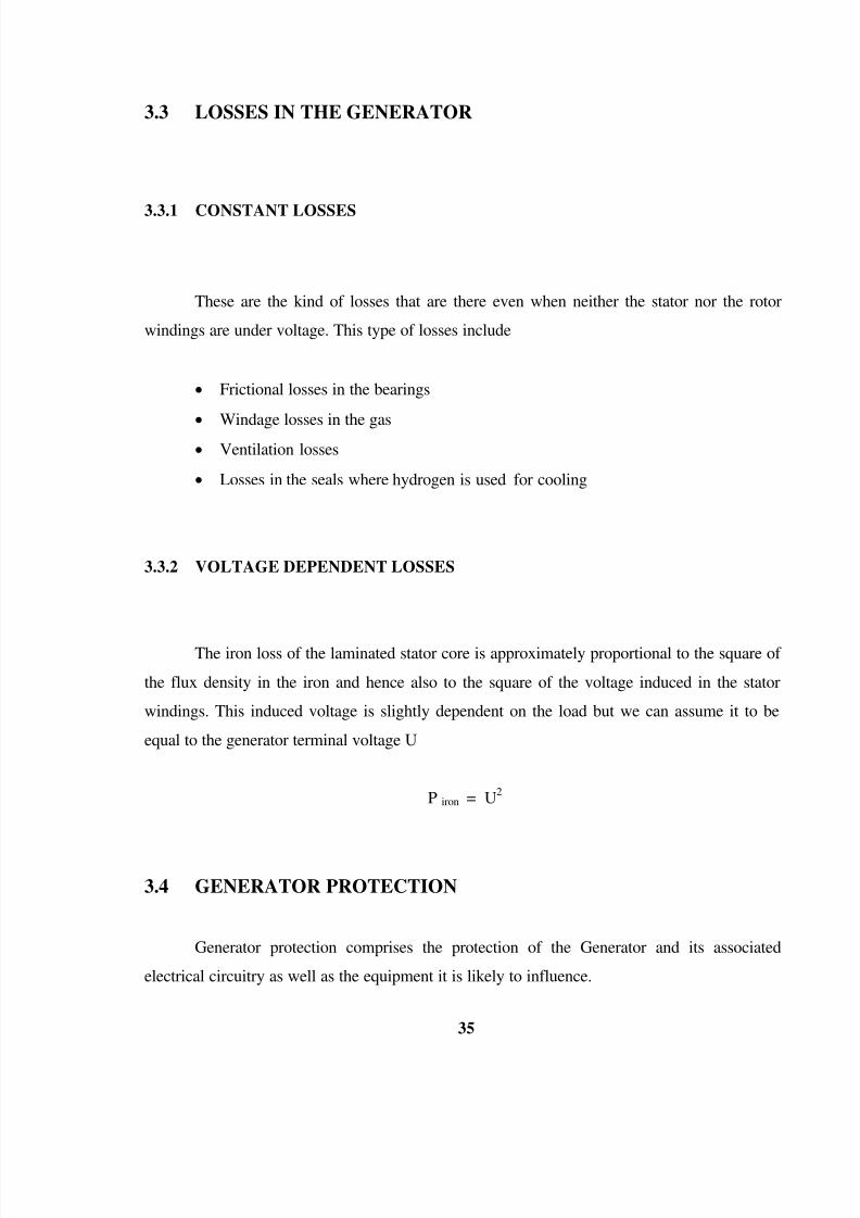
2.5 OVERVIEW OF WASTE HEAT RECOVERY BOILER 

Wagner-biro supplied boilers for anta combined cycle power plant known as waste heat

recovery boilers (WHRB), which are of non fired, dual pressure, forced circulation type. Theboiler has two different water/steam cycles known as high pressure system and low pressure

system. Each system has its own boiler drum and circulating pumps, and is feed by HP & LP

feed water pumps from a common feed water tank.

The HP&LP steam from the three boiler from four common headers HP live steam line,

HP bypass line, LP live steam line and LP bypass line, the bypass line dump steam in the

condenser through the HP and LP bypass system.

The HP steam drives the HP steam turbine through stop valves and control valves. The

LP steam after passing through stop valves and control valves mixes with the HP turbine

exhaust and drivers the gas turbine. This dual system of operating utilizes the waste heavy

8/3/2019 Reports NTPC

http://slidepdf.com/reader/full/reports-ntpc 29/53

29 

from the gas turbine with maximum efficiency. From LP turbine steam enters the condenser

where it get condensed to water with the help of cooling water .condenser is shell and tube,

water flow through the tubes and steam flow out side. The condensate get collected in hot well,

from hot well it enters the feed water tank through condensate.

Each of the WHRB is feed with waste heat flue gas from the respective gas turbine

(GT). The gas turbines are fired either with gas or naphtha. The energy from waste heat flue

gas is transferred to water/steam by means of heating surfaces of super heaters, evaporators,

economizers and condensate preheater. The steam-water system consists of a high (HP) and

low (LP) pressure system and in addition there is a condenser preheated in order to obtain a

higher efficiency.

2.5.1 LP BOILER PART

  Economizer: The LP feed water, which flows from the 3 X 50% LP feed water pumps

through the common feed water line to the WHRB‟s in parallel, enters a WHRB at

economizer gate valve. In the economizer the feed water is heated up by the flue gas.

After the economizer the feed water enters the LP boiler drum through feed regulating

station (FRS), where the feed  water control valve ensures the correct supply of feed

water to the boiler.

  Boiler Drum Evaporator: The feed water in the LP boiler drum is pumped through

the evaporator by means of 2 x 100% LP circulation pumps. In the evaporator the water

is partially steamed by the flue gas passing at the outside of the evaporator tubes. The

steam and water mixture again enters the drum, where steam is separated and this steam

flows to the LP super heaters and the water is circulated again.

  LP Super Heater: The steam leaving at the top of the LP-drum flows through the flue

gas heated super heater, where it reaches the end temperature of about 206 Centrigrade.

8/3/2019 Reports NTPC

http://slidepdf.com/reader/full/reports-ntpc 30/53

30 

2.5.2 HP BOILER PART 

The principal design of the HP- boiler part is the same as for the LP- part. The basic

difference is of operating pressure.

  Economizer: The HP fed water, which flows from the 3 x 50% HP feed water pumps

through the common the feed water line to the HP parts of 3 WHRB in parallel, enters a

WHRB at the gate valve of economizer. This gate valve is equipped with a parallel

bypass valve as in LP-economizer.

 Boiler Drum Evaporator: The feed water in the HP- boiler drum is pumped throughthe evaporator by means of 2 x 100% HP circulation pumps in the evaporator water is

partially steamed as in LP part, this partially steamed water enters in HP drum where

steam is separated, and water is circulated again. Theses steam is super heated in HP

super heater. The HP circulation pumps ensure the correct water flow through

evaporator for which differential pressure switches are provided.

  HP Super Heater: The HP super heater consists of two parts with a spray attemperator

between them. This configuration allows the temperature control of the super heated

steam. The spray water which is the cooling medium is branched from the feed water

line at the HP economizer inlet via a control valve to the attemperator if the temperature

of super heater increases beyond the predetermined temperature.

  Condensate Preheater: The main condensate is pumped by 3 x 50% condensate

extraction pumps (CEP) to the feed water tank. Before entering the feed water tank the

condensate is passed through the condensate preheaters which are situated at the tail

end of the WHRB and heated by the flue gas to achieve the highest cycle efficiency.

  Blow down Tank: One blow down tank is provided for each WHRB to collect drains

e.g. CBD, IBD and drum over flow water from hp and LP system of the WHRB. The

water level in this tank is maintained through an over flow pipe, which leads the water

to hot drain collecting system. The steam flows via a silencer to the atmosphere.

8/3/2019 Reports NTPC

http://slidepdf.com/reader/full/reports-ntpc 31/53

31 

2.6 OVERVIEW OF STEAM TURBINE

Photo 2.7 Steam Turbine Floor

The steam turbine plant consists of a single shaft condensing turbo set with HP & LP

live steam admission and with HP & LP bypass steam system. The steam generating plant

consists of three waste heat recovery boilers (drum type) with common live steam lines.

Exhaust gases of one appropriate gas turbine heat each boiler.

Normally, the whole steam generated in boilers flows through the turbo set. Part of 

steam can be bled via extraction lines to preheat the intake air for gas turbines. After expansion

in turbine, the remaining steam is condensed in the condenser. From there on, the condensate is

8/3/2019 Reports NTPC

http://slidepdf.com/reader/full/reports-ntpc 32/53

32 

fed through the gland steam condenser to a common feed water tank. The common HP & LP

feed water pumps supply the feed water to the three waste heat recovery boilers.  

The steam turbo set is composed of a single flow HP turbine and one double flow LP

turbine arranged one after the other with tandem compounding. The HP turbine has 25 stages

and LP turbine has 2 x 6 stages of reaction blading. The generator is directly coupled to the

shaft of the LP turbine.

The cross over piping between the HP & LP brings the expanded steam of HP Turbine

to the reaction blading in the LP turbine, where it expands down to the condenser pressure.

2.6.1 HP TURBINE

The high-pressure turbine is a single shell casing design. It consists of the turbine

casing, the fixed blade carriers, the dummy piston and the HP rotor.

2.6.2 LP TURBINE

The LP turbine is a double flow design .It consists of the welded turbine casing, the

fixed blade carriers and the LP rotor.

The LP casing is a welded fabrication from steel plate and is flanged together along the

horizontal plane at turbine axis height and LP rotor is a welded design mate of plain steel.

8/3/2019 Reports NTPC

http://slidepdf.com/reader/full/reports-ntpc 33/53

33 

CHAPTER 3

GENERATOR

3.1 BASIC DESIGN AND TYPES

Generators used in the power plants for the generation of electrical energy are

Synchronous machines. Basically we have two types of generators depending upon the speed

at which the machine is driven. These are:

  Turbo Generators driven by steam or gas turbines.

  Salient pole machines driven by hydraulic turbines or diesel engines and small steam

turbines with gearing.

Speed covers a wide range from 60 rpm to 1500 rpm depending on the number of poles

chosen or the prevalent water condition (in hydraulic plants).

The laminated stator core, with slots for the three-phase winding, is in principle the

same. The rotor, with the D.C supplied field windings, which generates the rotating field are

designed in different ways:

  Salient pole with concentrated windings.

  Non salient pole with the field windings distributed in slots.

8/3/2019 Reports NTPC

http://slidepdf.com/reader/full/reports-ntpc 34/53

34 

3.2 GENERATOR 

In a Generator, the magnetic field rotates as a consequence of the rotation of the rotor.

This produces in the stator an alternating field, which induces voltage in the stator windings.

Because of the alternating field the stator core must be composed of laminated stampings (i.e. a

laminated stator core). The construction with the solid core would result in induced eddy

currents, which would dampen the field. Also the losses produced will be enormous.

The stator has a three-phase winding and the three windings are displaced in air by 120 

and hence the voltages induced in the winding have a 120 phase shift.

This equation gives the criteria for determining the basic dimensions of the generators.

S = k A B d2

l n = c d2

l n

S = rated apparent power

d = rotor diameter

l = active length

c = utilization factor

Hence we see that the power output solely depends upon the diameter and the length of the

rotor. Therefore if we need to increase the power output we can either increase the length or

the diameter. But in the present circumstances we cannot increase the diameter beyond a

certain limit (due to the high speed of operation of the rotor) and hence the length goes up. In

case of the hydel power plants since the speed of operation is less we can afford to have large

diameter of the rotor and hence the effective size reduces.

8/3/2019 Reports NTPC

http://slidepdf.com/reader/full/reports-ntpc 35/53

35 

3.3 LOSSES IN THE GENERATOR 

3.3.1 CONSTANT LOSSES

These are the kind of losses that are there even when neither the stator nor the rotor

windings are under voltage. This type of losses include

  Frictional losses in the bearings

 Windage losses in the gas

  Ventilation losses

  Losses in the seals where hydrogen is used for cooling

3.3.2 VOLTAGE DEPENDENT LOSSES

The iron loss of the laminated stator core is approximately proportional to the square of 

the flux density in the iron and hence also to the square of the voltage induced in the stator

windings. This induced voltage is slightly dependent on the load but we can assume it to be

equal to the generator terminal voltage U

P iron = U2

3.4 GENERATOR PROTECTION

Generator protection comprises the protection of the Generator and its associated

electrical circuitry as well as the equipment it is likely to influence.

8/3/2019 Reports NTPC

http://slidepdf.com/reader/full/reports-ntpc 36/53

36 

The protection basically protects

  Abnormal Running Conditions: Equipment, though entirely in order, can be

overloaded. The overloading parameters can be current, voltage, frequency,

temperature or saturation. Such abnormal running conditions, if allowed to continue,

may well lead to a fault. Often it is possible to normalize such abnormalities after

necessary alarm is initiated through protection.

  Fault Conditions: Here it is a must to isolate the faulty circuitry/equipment through

protection to minimize the damage.

3.5 MAJOR FAULTS 

  Over-current

  Over-voltage

  Reverse Power  Over temperature and Mechanical Danger

  Over-flux (Saturation)

  Earth Fault Protection

  Differential Protection

8/3/2019 Reports NTPC

http://slidepdf.com/reader/full/reports-ntpc 37/53

37 

3.5.1 OVER CURRENT PROTECTION 

In general, over-current protection comprises of current transformers which step down

the primary current to lower value. The over-current protection is used in the generator

protection as

  Back up protection at internal overloads and faults

  Main or back up protection at external faults

3.5.2 OVER VOLTAGE PROTECTION

In general, over-voltage protection comprises of voltage transformers which step down

the terminal voltage to lower value. The scaled down voltage is fed to the relay. The relay

picks up when the voltage value crosses its setting and isolates the circuit by opening the

required circuit breaker.

3.5.3 REVERSE POWER PROTECTION 

The reverse power protection is for the protection of generators & specially its prime

mover against over speed.

3.5.4 OVER TEMPERATURE AND MECHANICAL DANGER

Continuous operation without input is not permissible for all types of prime movers in

general & steam turbine in particular because of the increased mechanical & thermal stresses to

8/3/2019 Reports NTPC

http://slidepdf.com/reader/full/reports-ntpc 38/53

38 

avoid mal-operation of this protection during load pick up after synchronization or sudden load

change, small time delays are used.

3.5.5 OVER FLUX PROTECTION

The over-flux protection is meant to protect the magnetic circuits from saturation &

overheating. Saturation is a phenomenon which occurs when magnetic intensity or loading of 

the machine exceeds the value for which the machine is designed for. Higher degree of 

saturation can cause overheating of magnetic circuits by increased magnetic circuit losses &

can lead to mal-operation of differential protection by higher magnetizing current.

3.5.6 EARTH FAULT PROTECTION 

Earth fault protection is the protection of electrical circuits against damage caused by

earth fault.

  STATOR EARTH FAULT PROTECTION: The earth-fault is caused as a result of 

insulation breakdown. Inside a generator, even a small amount of earth-fault current for

a considerable duration of time may lead to catastrophic failure as it results in gradual

overheating of laminated iron in core causing short circuit in the lamination which

results in further overheating of magnetic circuits. A great care is therefore taken to

protect the generator from earth faults.

  STARTING EARTH FAULT: This protection is used only in case of GT Generator.

This protection activates if an earth-fault occurs when the generator is on no load

condition & yet to be synchronized i.e. Generator breaker is not closed.

8/3/2019 Reports NTPC

http://slidepdf.com/reader/full/reports-ntpc 39/53

39 

  ROTOR EARTH FAULT PROTECTION: The rotor earth-fault protection is the

protection of the rotor winding against earth-fault. The rotor winding is fed by DC

excitation voltage which is not grounded. Hence, a single point earthing in rotor

winding is not dangerous as no earth current can flow as no return path is there. This is

the reason behind providing only alarm for a single point earthing in rotor winding.

However, a second earth-fault at this point of time can be very damaging for the rotor

& calls for immediate withdrawal of the generator from the grid.  

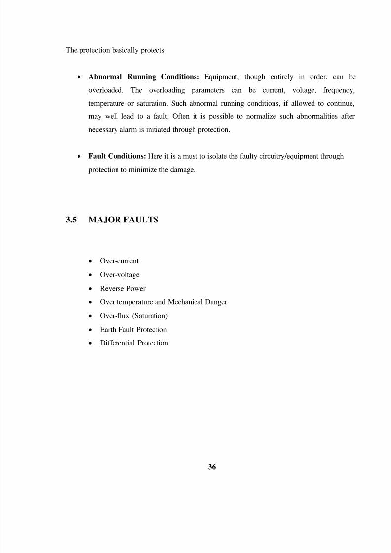
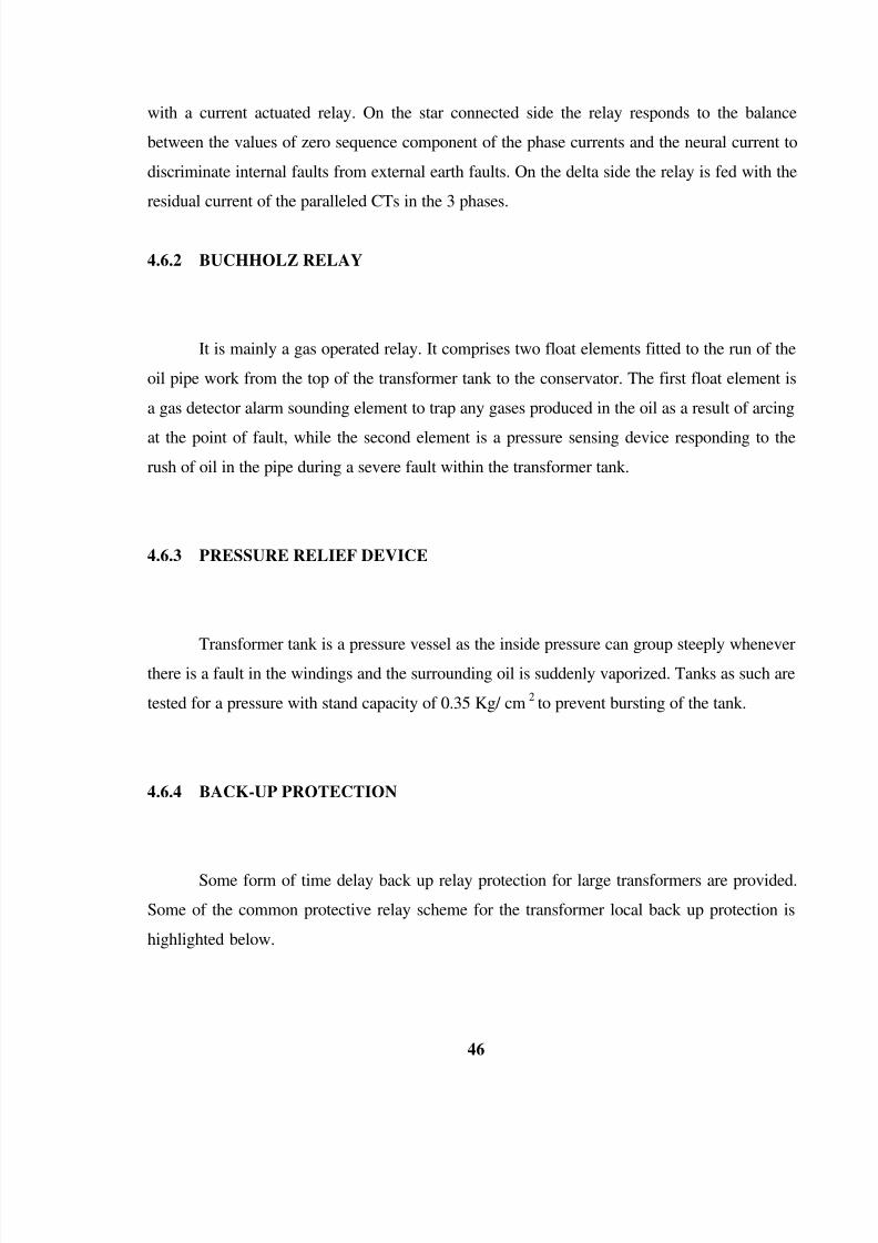
3.5.7 DIFFERENTIAL PROTECTION

As the name implies, differential protection is the protection for difference in parameter

of current. In any electrical system, each equipment shall be having incoming current &

outgoing current. In normal condition, both of them shall be equal.

However, whenever the equipment develop an internal fault, there will be a difference

in the current parameters in magnitude depending on severity & type of the fault as well as its'exact location. The protection, seeing the difference, shall be activated & isolate the

equipment.

8/3/2019 Reports NTPC

http://slidepdf.com/reader/full/reports-ntpc 40/53

40 

CHAPTER 4

TRANSFORMER 

The generator is connected to transformers by means of isolated bus ducts. This

transformer is used to step up the generating voltage of 15.75 KV to grid voltage of 220 KV.

This transformer is generally provided with OFAF cooling. It is also provided with off load / 

on load taps on the high voltage side. This transformer has elaborate cooling system consisting

of number of oil pumps and cooling fans.

4.1 SPECIFICATION OF GENERATOR TRANSFORMER 

Rated power 160 MVA

KV (no load) HV 230

KV(no load)HV 15.75

Ampere HV 728

Amperes LV 10630.6

Phases 3

Frequency 50

Types of cooling OFAF (oil forced air forced )

Ambient oil tempO

C 50

Ambient winding temp.O

C 55

Connection Symbol Ynd11

Table 4.1 Specification of Generator Transformer 

8/3/2019 Reports NTPC

http://slidepdf.com/reader/full/reports-ntpc 41/53

41 

4.2 UNIT AUXILIARY TRANSFORMER 

The unit auxiliary transformer draws its input from the main bus duct connecting

generator to the generator transformer. With higher unit ratings and higher steam conditions,

the auxiliary power required also increases. For large units, it has become necessary to use

more than one auxiliary transformer. UAT‟s used at the plant are both tree winding and two

winding transformer. These UAT‟s are used to step down the voltage at two levels for different

works. The 2.55 KV lines are used for the generator starting equipments while the 0.433 KV

lines are used to operate the generator auxiliaries.

Rated power 6300 MVA (5050 MVA + 1250 MVA)

Rated voltage no load HV 15.75 KV

Rated voltage no load LV side 2.55 KV and 0.433 KV

Rated current HV side 230.9 A

Rated voltage LV side 1143 A and 1667 A

Frequency 50 Hz

Vector symbol D,Y1,YN1

Table 4.2 Specification of UAT

4.3 CAPACITIVE VOLTAGE TRANSFORMER 

It consists of a capacitive potential divider and an inductive medium voltage circuit.

The CVT is useful for bilateral purposes to facilitate protection, metering and communication

in the high voltage system. The end of the bottom one capacitance is connected to the high

frequency (HF) point which further connects to the PLCC system which is to be used for the

8/3/2019 Reports NTPC

http://slidepdf.com/reader/full/reports-ntpc 42/53

42 

protection of the entire high voltage system and communication purpose as well . The other

end of the same capacitor is connected directly to the primary side of the transformer,

immersed in the oil, and the transformed voltage is used for metering and control purpose.

4.4 INTER CONNECTED TRANSFORMER 

These are single-phase auto transformer used to change the amplified generated voltage

to different levels to feed the different power lines.

4.5 CONSTRUCTIONAL DETAILS OF THE TRANSFORMER 

4.5.1 TANK

It is of welded construction and fabricated from tested quality low carbon steel. All

seams and joints are factory welded. Tanks stiffeners are provided for general rigidity and are

designed to prevent retention of water. It is designed to withstand:

  Mechanical shocks during transportations

  Vacuum filling of the oil

 Short circuit forces

Tank shields are made up of magnetically permeable material so that no magnetic fields

shall exist outside the tank.

8/3/2019 Reports NTPC

http://slidepdf.com/reader/full/reports-ntpc 43/53

43 

4.5.2 TANK COVER

It is sloped to prevent retention of rain water. The tank cover is filled with pockets at

the position of max oil temp and winding temp indicators. All the bolted connections are fitted

with weather proof, hot oil resistant gaskets in between for complete oil tightness.

4.5.3 PRESSURE RELIEF DEVICES

This is provided for the rapid release of any pressure that may be generated in the tank 

and which may result in the damage of the equipment. It is mounted directly on the tank and

operates at static pressure of less than hydraulic test pressure of the tank.

4.5.4 BUCHHOLZ RELAY

A double float reed type Buchholz relay is provided. Any gas involved in the

transformer is collected in this relay. A copper / stainless steel tube may be connected from the

gas collector to a valve located about 1200 mm above the ground level to facilitate sampling

with the transformer in service.

The device is provided with two electrically independent ungrounded contacts; one for

alarm for gas accumulation and the other for tripping on sudden rise of temperature.

8/3/2019 Reports NTPC

http://slidepdf.com/reader/full/reports-ntpc 44/53

44 

4.5.5 CORE

It is constructed from high grade non ageing cold rolled supper grain oriented silicon

steel lamination, known as HI-B. The core is designed so as to avoid static discharges,

developments of short circuit paths within itself or to the earth clamping structures

4.5.6 WINDINGS

The windings of all 220 KV type transformer are made in dust proof, conditioned

atmosphere. The insulation of the transformer windings and the connections are to be made

free from insulating compounds which are liable to soften, ooze out, shrink or collapse or are

chemically active.

4.5.7 INSULATING OIL

Oil is used as coolant and dielectric.

4.5.8 CONSERVATOR TANKS

Conservator tank is designed such that the lower part acts as sump to meet the

requirements of expansion of the total coil oil volume in the transformer. A valve is fitted at

the lowest point of the conservator for oiling and sampling.

8/3/2019 Reports NTPC

http://slidepdf.com/reader/full/reports-ntpc 45/53

45 

4.5.9 SILICA GEL BREATHER

The conservator is filled with dehydrating silica gel breather. The silica gel crystals in

the breather act as an indicator and turn pink from blue when they absorb moisture. After

majority of the crystals have turned pink the silica gel should be heated at around 150-200

degree until the original color is obtained.

4.5.10 TAP CHANGING EQUIPMENTS

The transformer is provided with off circuit tap changing switch for varying its

effective ratio transformation while the transformer is de-energized.

4.6 PROTECTIVE SCHEMES FOR POWER TRANSFORMERS 

A Power Transformer constitutes an important and expensive component in a power

system. It is therefore essential to provide an efficient protective relay scheme to protect the

transformer from any severe damage which is likely to be caused by short circuited faults

within the equipment itself or from any sustained overload or fault condition in the power

systems.

4.6.1 RESTRICTED EARTH FAULT RELAY 

One of the schemes adopted for detection of earth fault in the transformer zone is a

restricted earth fault relay system. In this method, each transformer winding will be provided

8/3/2019 Reports NTPC

http://slidepdf.com/reader/full/reports-ntpc 46/53

46 

with a current actuated relay. On the star connected side the relay responds to the balance

between the values of zero sequence component of the phase currents and the neural current to

discriminate internal faults from external earth faults. On the delta side the relay is fed with the

residual current of the paralleled CTs in the 3 phases.

4.6.2 BUCHHOLZ RELAY

It is mainly a gas operated relay. It comprises two float elements fitted to the run of the

oil pipe work from the top of the transformer tank to the conservator. The first float element is

a gas detector alarm sounding element to trap any gases produced in the oil as a result of arcing

at the point of fault, while the second element is a pressure sensing device responding to the

rush of oil in the pipe during a severe fault within the transformer tank.

4.6.3 PRESSURE RELIEF DEVICE

Transformer tank is a pressure vessel as the inside pressure can group steeply whenever

there is a fault in the windings and the surrounding oil is suddenly vaporized. Tanks as such are

tested for a pressure with stand capacity of 0.35 Kg/ cm2

to prevent bursting of the tank.

4.6.4 BACK-UP PROTECTION

Some form of time delay back up relay protection for large transformers are provided.

Some of the common protective relay scheme for the transformer local back up protection is

highlighted below.

8/3/2019 Reports NTPC

http://slidepdf.com/reader/full/reports-ntpc 47/53

47 

  Inverse Definite Minimum Time (I.D.M.T) Relay: The time of operation of this relay

is depended upon the magnitude of the fault current, being comparatively long for low

fault current and short for high fault current.

  Definite Time over Current Relay: In this method the relay has anadjustable definite

time setting.

  Instantaneous Relay: This type of relay trips instantaneously without time delays as

soon as it senses the fault.

4.6.5 DIFFERENTIAL RELAY 

In this method, each transformer winding is provided with CT. A Differential Relay is

connected across the terminals of the CTs. In normal conditions direction of the currents

through both the CTs are same. Whenever there is a fault condition the direction of current

through one CT changes and the two current add up. The relay senses this large current and

gives trip command. In this protection scheme the magnitude as well as the phases difference

between the current of the two sides of the transformer is taken care of . The magnitude is

taken care of by using the CT‟s of proper ratios (different on each side). The phases lag or lead

is compensated by using another CT which has an opposite connection scheme ,ie, if the

transformer under consideration is a delta/ star transformer then we use a CT that I has star / 

delta scheme .

8/3/2019 Reports NTPC

http://slidepdf.com/reader/full/reports-ntpc 48/53

48 

4.7 VARIOUS TESTS OF THE TRANSFORMER

4.7.1 RATIO TEST 

This test is to test the transformation ratio of the transformer. To do this test we give a

small value of voltage at the HV side and measure the corresponding voltage at the LV side.

We can then calculate the transformation ratio

4.7.2  MAGNETIZING CURRENT TEST 

To test this we make use of a tongue tester. We apply a certain voltage at the primary

and test the corresponding value or current.

4.7.3  PERCENTAGE IMPEDANCE TEST 

Here we calculate the P.U value of the impedance of the transformer winding. P.U

values are same for both LV and HV side.

4.7.4  TEST FOR BDV (BREAK DOWN VOLTAGE) OF OIL 

It done to check the voltage at which the oil breaks down. Practically it should be at

least 40KV/mm. At NTPC this limit is set at 50 KV/mm.

8/3/2019 Reports NTPC

http://slidepdf.com/reader/full/reports-ntpc 49/53

49 

4.7.5 TEST FOR MOISTURE CONTENT IN OIL

The oil is tested for the amount of moisture in it, in the chemistry lab. Special care is to

be taken at the time of taking out the oil that is to be tested. The oil content should be < 100

ppm.

8/3/2019 Reports NTPC

http://slidepdf.com/reader/full/reports-ntpc 50/53

50 

CHARACTER 5

POWER EVACUATION FROM NTPC ANTA 

Photo 5.1 Switchyard at NTPC Anta

Anta Gas Power Project constructed by NTPC is located in Baran district of Rajasthan.

The power generated is being sold to the beneficiary states of Northern Region. In order to

evacuate power from this 4 GPP, it has been decided to construct 220 KV AC transmission

system based on the discussions with CEA.

.

8/3/2019 Reports NTPC

http://slidepdf.com/reader/full/reports-ntpc 51/53

51 

The transmission system indicated in the Feasibility report is given as follows.

  220KV D/C Anta-Bhilwara line 230 Km.

  220KV D/C Anta-Dausa line 300 Km.

  Extension of 220 KV s/s of RSEB at Bhilwara and Dausa.

5.1 SWITCHYARD

220 KV Switchyard is the place at which switching operation of power distribution is

formed. All modern generating station uses a unit system of generation transformer

connection. This unit is connected through circuit breaker and isolated to the high frequency

voltage bus. The output of generator is connected through high voltage side and low voltage

side is connected to the bus.

5.1.1  BUS BARS

The bus bar arrangement is of single sectionalized bus bar. In this type of bus bars is

divided into two section connected by bus coupler. These buses are made of 2 ASCR

conductor 250 mm. It has 6 feeders. There is more us which is known as auxiliary bus bas.

8/3/2019 Reports NTPC

http://slidepdf.com/reader/full/reports-ntpc 52/53

52 

5.1.2 BUS COUPLER

Bus coupler is used to couple two busses together. Bus coupler consists of a circuit

breaker and the isolator which are situated at both side of circuit breaker.

5.1.3 CURRENT TRANSFORMER

The current transformer is used with its primary winding connected in series with line

carrying the current to be measured. The primary winding consists of very few turn and

therefore there is no appropriate voltage drop across it. The secondary winding has larger

number of turns. Ammeter terminal is connected terminal. Thus a current transformer under

SC condition the secondary rating current is 5A.

5.1.4  POTENTIAL TRANSFORMER

Potential transformer is used to operate the voltmeter the potential coil of volt meter

and relays from high voltage lines. The primary winding is connected across the line/joining

carrying the voltage to be measures. The secondary winding is so designed that the voltage of 

100V to 120 V is delivered to instrument load the normal secondary winding rating is 110 V.

5.1.5 ISOLATING SWITCH

Whenever the maintenance and repair work is carried out on equipment in a switchyard, it is

disconnected from a supply by the isolator.

8/3/2019 Reports NTPC

http://slidepdf.com/reader/full/reports-ntpc 53/53

REFERENCES

  WWW.NTPC.CO.IN  

   NTPC PROVIDED MATERIAL

  WWW.WIKIPEDIA .ORG


Recommended