Research and Development of Additive Manufactured Bladed Disks Collaboration between Chalmers, Penn State and GKN Aerospace Bachelor’s thesis in Mechanical Engineering John Austin Bayliff Adam Billberg Rasmus Blom Nicole Gallegor Oscar Holke Stephen Sandford Department of Applied Mechanics Department of Mechanical and Nuclear Engineering CHALMERS UNIVERSITY OF TECHNOLOGY PENNSYLVANIA STATE UNIVERSITY Gothenburg, Sweden 2017 State College, Pennsylvania, United States of America 2017
Transcript
Research and Development of AdditiveManufactured Bladed DisksCollaboration between Chalmers, Penn State and GKN Aerospace
Bachelor’s thesis in Mechanical Engineering
John Austin Bayliff
Adam Billberg
Rasmus BlomNicole Gallegor
Oscar HolkeStephen Sandford
Department of Applied Mechanics Department of Mechanical andNuclear Engineering
CHALMERS UNIVERSITY OF TECHNOLOGY PENNSYLVANIA STATE UNIVERSITYGothenburg, Sweden 2017 State College, Pennsylvania, United States
of America 2017
Bachelor’s thesis 2017:09
Research and Development of AdditiveManufactured Bladed Disks
Collaboration between Chalmers, Penn State and GKN Aerospace
John Austin BayliffAdam BillbergRasmus Blom
Nicole GallegorOscar Holke
Stephen Sandford
Department of Applied MechanicsChalmers University of Technology
Gothenburg, Sweden 2017Department of Mechanical and Nuclear Engineering
Pennsylvania State UniversityState College, Pennsylvania, The United States of America, 2017
Research and Development of Additive Manufactured Bladed DisksCollaboration between Chalmers, Penn State and GKN AerospaceJOHN AUSTIN BAYLIFF, ADAM BILLBERG, RASMUS BLOM, NICOLE GAL-LEGOR, OSCAR HOLKE, STEPHEN SANDFORD
Supervisor: Prof. Mikael Enelund, Department of Applied MechanicsExaminor: Prof. Magnus Ekh, Department of Applied MechanicsSupervisor: Prof. Jason Moore, Department of Mechanical and Nuclear Engineering
Bachelor’s Thesis 2017:09ISSN 1654-4676 Department of Applied MechanicsChalmers University of TechnologySE-412 96 GothenburgTelephone +46 31 772 1000
Printed by Chalmers ReproserviceChalmers University of TechnologyGothenburg, Sweden 2017
iv
Research and Development of Additive Manufactured Bladed DisksCollaboration between Chalmers, Penn State and GKN AerospaceJ. BAYLIFF, A. BILLBERG, R. BLOM, N. GALLEGOR, O. HOLKE, S.SANDFORD
Abstract
The contemporary manufacturing methods for bladed disks, also known as “blisks”,cause a great deal of material waste. To reduce the material waste and increasethe freedom of design, GKN Aerospace requested this project to evaluate additivemanufacturing (AM) as a manufacturing method for blisks. Additive manufacturingmethods were researched and evaluated based on mechanical properties, freedom ofdesign, material use, and production times. Finite Element Analyses with respectiverotation and pressures have been performed and reviewed. All researched methodshave been found to have the ability to fulfill the requirements by GKN Aerospace:Power Bed Fusion (PBF) methods and Direct Energy Deposition (DED) methods.
This bachelor thesis is a collaboration between GKN Aerospace and students fromChalmers University of Technology and Pennsylvania State University. GKN Aerospaceprovided the project with CAD models on the current blisk design as well as dataabout loads and temperatures for the simulations. They also provided a list of pa-rameters for the design including restrictive safety standards and production times.GKN Aerospace stated that Titanium-64 (TiAl6V4) is the preferred metal alloy forproduction. A large part of the project was to examine and study different methodsof additive manufacturing in consideration for the production of blisks. The bestmethod was identified and specified to fit the needs of GKN Aerospace. The teamhad access to a running Gantt Chart scheduling tool to remain on task and ensurethat all parameters of the project were met throughout the semester long project.The team also stayed within the outlined budget, only spending $260.56 on traveland prototyping expenses.
The main problem with contemporary additive manufacturing machines utilizingPBF are their relatively small size which led to researching joining techniques. Forthe DED methods researched, the main problem faced were geometric restrictionsin printing complex structures. After reviewing the objectives and comparing themusing a Pugh matrix, it was determined what concept would work best for GKNAerospace. Electron Beam Melting (EBM), a PFB method, should first be used toprint the blisk in sections. Then, the pieces should be joined together using Elec-tron Beam Welding (EBW). After this the blisk should be heat treated using HIPand finally machined to reach desirable surface textures. Further evaluation of themechanical properties of EBM TiAl6V4 and EBW will need to be done by GKNAerospace to ensure this design will work for this particular aerospace applicationshould they choose to move forward with this concept.
Den nutida tillverkningsmetoden for bladed disks, aven kallade“blisks”, orsakar storamaterialforluster. For att minska pa materialforlusterna och oka designfriheten harGKN Aerospace forsett projektet med uppgiften att utvardera additiv tillverkning(AM) som en tillverkningsmetod for blisks. Metoder for additiv tillverkning under-soktes och utvarderades med avseende pa mekaniska egenskaper, designfrihet, ma-terialanvandning, och produktionstider. Finita element analyser genomfordes medtryck och rotation implementerat vilka sedan analyserades. Projektet kom fram tillatt alla studerade AM metoder klarar de krav som stallts av GKN Aerospace: Pow-der Bed Fusion (PBF) metoder och Direct Energy Deposition (DED) metoder.
Denna kandidatuppsatts ar ett samarbete mellan GKN Aerospace, studenter franChalmers tekniska hogskola samt studenter fran Pennsylvania State University. GKNAerospace tillhandahall projektet med CAD modeller av en blisk samt data om lasteroch temperaturer for simuleringarna. De tillhandaholl aven en lista over parame-trar for designen sasom sakerhetsparametrar och produktionsparametrar. GKNAerospace angav att det ar onskvart att anvanda legeringen (TiAl6V4) for pro-duktionen. En stor del av projektet har bestatt av att undersoka AM metoder somkan tillampas i projektet. Den basta metoden identifierades och specificerades foratt passa GKN Aerospaces behov. Laget hade tillgang till ett lopande Ganttschemafor att inte avvika fran uppgiften och se till att projektets tid anvandes val. Lagetholl sig aven inom den angivna budgeten och anvande endast 2300 kr for resor ochprototypkostnader.
Det storsta problemet med AM maskiner som nyttjar PBF ar deras relativt smautskriftskammare vilket ledde till att aven fogningsmetoder undersoktes. For DEDvar det storsta problemet restriktioner i att skriva ut komplicerade geometrier. Efteratt ha utvarderat malen i projektet valdes det basta konceptet, som uppfyllde GKNAerospaces mal bast, ut genom att anvanda en Pughmatris. Electron Beam Melting(EBM) som ar en metod for PBF, ska forst anvandas for att skriva ut blisken i sek-tioner. Dessa delar ska sedan fogas samman med Electron Beam Welding (EBM).Efter detta ska delarna varmebehandlas med HIP och slutligen svarvas sa att entillrackligt fin yta uppnas. Ytterligare utvardering av materialegenskaperna forTiAl6V4 och egenskaper hos EBW bor genomforas av GKN Aerospace om de valjeratt vidareutveckla konceptet.
The group has had help from several external sources, and we would like to thankthem for their contributions to this report. At Penn State, professors Tim Simpsonand Todd Palmer provided feedback on concepts based on their expertise in additivemanufacturing. A special thanks is given to Mikael Enelund and Jason Moore forworking closely with the team throughout the course of the project. A big thanks tothe Mechanical Engineering department at Chalmers and (again) Mikael Enelund,for sponsoring and administrating the visit to Penn State for the Chalmers students.It was very appreciated!
Additionally, the group thank GKN Aerospace for providing a challenging and re-warding project and Stefan Forsman for offering guidance and feedback throughoutthe project.
R. Blom, A. Billberg, O. Holke, Gothenburg, 2017J. Bayliff, N. Gallegor, S. Sandford, State College Pennsylvania, 2017
vii
Nomenclature
The next list describes several abbreviations and symbols that will later be usedwithin the body of the document.
Additive manufacturing methodsAM Additive ManufacturingDED Direct Energy DepositionDMLM Direct Metal Laser MeltingDMLS Direct Metal Laser SinteringEBAM Electron Beam Additive ManufacturingEBM Electron Beam MeltingLENS Laser Engineering Net SystemPBF Powder Bed FusionSLM Selective Laser MeltingSLS Selective Laser SinteringOtherAHP Analytic Hierarchy ProcessASME American Society of Mechanical EngineersASTM American Society for Testing and Materials InternationalCAD Computer Aided DesignCNC Computer Numerical ControlPLA Polylactic acidUTS Ultimate Tensile StrengthPost processingCIP Cold isostatic pressingHIP Hot isostatic pressingList of symbolsα Angle of blade between axial and tangential directionω Rotational velocityAtot Combined front surface area of all bladesFnormal Force normal to bladeFtan Force tangential to blisk rimM MomentP Workp Pressure on blader Radius to centre of bladeWelding methodsEBW Electron Beam Welding
ix
GTAW Gas Tungsten Arc WeldingLFW Linear Friction Welding
2.1 Illustration of Powder Bed Fusion method with powder roller. . . . . 72.2 Example of DED process . . . . . . . . . . . . . . . . . . . . . . . . . 82.3 Simplified figure of process inherent surface roughness for different
stages of melted metal powder. The above figure shows a lower de-gree of melt than the lower figure, resulting in a less clear separationbetween different powder spheres . . . . . . . . . . . . . . . . . . . . 15
2.4 Three Stages of Linear Friction Welding adapted from [27] . . . . . . 18
3.1 Illustrating risk level based on impact and probability . . . . . . . . . 233.2 Shape of evaluated blisk . . . . . . . . . . . . . . . . . . . . . . . . . 263.3 Boundary condition of blisk in ANSYS . . . . . . . . . . . . . . . . . 303.4 Rotational velocity and pressure as load on blisk in ANSYS . . . . . 303.5 Mesh of blisk for stress analysis . . . . . . . . . . . . . . . . . . . . . 323.6 Mesh of blisk for fatigue analysis . . . . . . . . . . . . . . . . . . . . 323.7 Comparison of build speed for DED and PBF adapted from [16] . . . 35
4.1 von Mises stresses on opposite side of pressure load . . . . . . . . . . 404.2 von Mises stresses on same side as pressure load . . . . . . . . . . . . 414.3 von Mises stresses on the front of body . . . . . . . . . . . . . . . . . 414.4 von Mises stresses on the back of body . . . . . . . . . . . . . . . . . 424.5 Fatigue life with DED and reduction factor of 0.24 . . . . . . . . . . . 434.6 Fatigue life with EBM and reduction factor of 0.30 . . . . . . . . . . 444.7 Fatigue life with SLM and reduction factor of 0.35 . . . . . . . . . . . 444.8 Fatigue life with DMLS and reduction factor of 0.26 . . . . . . . . . . 454.9 Campbell diagram without pressures on the blades with machined
E.1 Each blade is fitted using an axial dovetail slot . . . . . . . . . . . . . XIE.2 Blades are fitted in a slot on the outer rim of the disk . . . . . . . . . XIIE.3 A locking pin holds the blade in place . . . . . . . . . . . . . . . . . . XIIE.4 A dovetail like contraption but with a fir tree shaped profile, Patent
F.1 Campbell table with pressures on the blades with machined EBM,see Table 3.5 . . . . . . . . . . . . . . . . . . . . . . . . . . . . . . . . XV
F.2 Campbell table with pressures on the blades with machined SLM, seeTable 3.6 . . . . . . . . . . . . . . . . . . . . . . . . . . . . . . . . . . XVI
F.3 Campbell table with pressures on the blades with machined DMLS,see Table 3.7 . . . . . . . . . . . . . . . . . . . . . . . . . . . . . . . . XVII
F.4 Campbell table with pressures on the blades with machined DED, seeTable 3.8 . . . . . . . . . . . . . . . . . . . . . . . . . . . . . . . . . . XVIII
xviii
1Introduction
The production of aerospace bladed fan disks is restricted by current forging andmanufacturing processes. Machining parts can often lead to warping of the finishedproduct or chipping. The functionality and compatibility of the finished bladeddisk can decrease as the parts are mismanufactured. Additive manufacturing (AM)has allowed for more freedom in the design of complex systems to be safer, moreaerodynamic, and more customized. These methods also create one solid part ratherthan having multiple assembly steps as in current dovetail designs. A variety of AMmethods are at the disposal of the aerospace industry including, but not restrictedto, Electron Beam Melting (EBM), Direct Metal Laser Sintering (DMLS), DirectedEnergy Deposition (DED), and Selective Laser Melting (SLM). Each method offersits own set of benefits as well as drawbacks.
1.1 Initial Problem Statement
Bladed disks, often referred to as blisks, are becoming more common in jet engines.Blisks can offer improved performance, larger design freedom, and are lighter thanconventional disks, however, because blisks are machined from a single piece of metal,there is substantial material waste. This makes repairing and replacing blisks quiteexpensive. To overcome these material losses, AM methods are being researched asa future manufacturing method for blisks. Aside from improving reliability, multiplesafety factors will also need to be considered when working with a rotating part suchas a blisk.
This semester, in a joint effort, students at Chalmers and Penn State worked togetherto research the AM capabilities for blisks. GKN Aerospace served as the industrialpartner and provided information to the students assisting them throughout thecourse of the project. GKN Aerospace is a well respected company in their industrywith a large interest in advanced manufacturing technologies. The team was able toprovide GKN with a feasible manufacturing design and recommendations of how toproduce a blisk utilizing AM.
1.2 Objectives
The goal of the project was to design a blisk that, with the use of AM, lowersthe material use significantly while maintaining the high performance of machineddisks. The blisk also needed to be able to be withstand at least 30,000 start-stop
1
1. Introduction
cycles. Two existing AM methods were explored to determine the best option forGKN: Powder Bed Fusion (PBF) and Direct Energy Deposition (DED). The finalproject also consisted of the specification of the requirements for the AM method toensure that the produced blisks are competitive alternatives. In addition to selectinga suitable AM method for GKN, a second goal included providing a structuralanalysis of the blisk design. Throughout the project, there were several limitationsand assumptions necessary to create a final proposal including the building envelopesize, limited economic data, and weakness of reputable material data.
1.2.1 Scope of Work
The project began with the identification of key performance indicators for blisks toensure that the blisks manufactured through AM would meet the performance re-quirements. Furthermore, a literature survey on AM-methods was carried out and afinal method was chosen that is believed to ensure the best result. The AM-methodswere evaluated with respect to the performance of the part.
The current blisk design was evaluated using computer simulations with ANSYSsoftware [6] during operational conditions focusing on stresses and the fatigue life.With this information the capabilities of AM methods for the parts were identified.The entire blisk could not be manufactured through AM in its entirety; therefore, aseparate joining and production method was investigated for the interfaces betweenmanufactured parts and AM parts.
1.2.2 Limitations
The project was restricted by a time constraint that played a factor in the finalresults of the project. The project team composed of three students from Chalmersand three student from PSU. The students from Chalmers worked on the projectfrom January 17th to May 23rd and the students from PSU worked on the projectfrom January 9th to May 1st.
Because of the students’ limited knowledge in this area of expertise, this lead to fur-ther limitations on the project. However, all students had some earlier experienceand knowledge in the areas. The project utilized the supervisors’ and other externalparties knowledge in areas like material properties, simulations and manufacturingtechniques to make sure that correct assessments were made.
Due to restrictions in budget, the team was unable to manufacture the final design asa metal prototype. Instead, a single blade was printed in aluminum from an externalcompany to use as a demonstration of the rough surface finish associated with AMmethods. A geometrically similar plastic prototype and analysis of the final designin metal were also done to support the recommendations being made. Furthermore,no physical tests on the AM-method were performed. Instead the sole focus of theproject was on theoretical analysis and computer simulations of the design.
2
1. Introduction
Safety factors had to remain within the same ranges as the current production meth-ods. Tolerances of the dimensions and the restrictions of the blisk environment alsohad to comply with the current blisk designs and methods. Ultimately, the finaldesign for the AM blisks had to fit the current assembly to be useful for GKNAerospace.
Due to the low level of maturity in the area of metal AM, a distinctive lack of datamade limitations on possible areas of evaluation necessary. One of these was theevaluation of creep properties.
AM enable exotic designs in the center parts of the blisk (disk) as well as in theblades. It can enable weight reductions by creating hollow and web-like structures.This is one of the reasons to why the group has chosen to limit the project toonly include blisks made using only AM methods. No combination of AM andconventional production methods will be evaluated more than briefly. A limitationwas also made to only evaluate solid blisks.
3
1. Introduction
4
2Theory
Since the subject of AM is relatively new, there is for many studies a lack of in-formation. The information that exists must be critically reviewed. That is whya comprehensive external search has been conducted, especially regarding materialproperties from different AM methods, and what characterizes them.
2.1 Existing Rotors
There are two main types of rotors used in the compressor part of today’s turbofanjet engines: conventional rotors and bladed disks. The main difference between themis that conventional rotors have removable blades while bladed disks are machinedfrom a single piece of metal. [2, 1]
2.1.1 Conventional Compressor Rotors
The center part of the rotor will from now on be called the “disk”. The “blades” arethe thin parts fastened on the outer rim of the disk. For conventional compressorrotors the disk and blades are manufactured separately and then joined together[25]. The disks are manufactured by either powder metallurgy, or machine cuttingand stamping, while machining is used to form the the blades. Dovetail joints arefrequently used to attach the blades to the disk [9]. Conventional rotors benefit frombeing able to exchange single blades if they would become damaged.
2.1.2 Bladed Disks
Bladed disks, or blisks, are the name of disks with the blades directly attached tothe center disk. This is achieved by milling the entire blisk from one solid blockof metal, rather than creating the blades separately and then assembling it. Thebenefits of this are an increase in fuel efficiency by up to 8% [13] and a reduced riskof crack initiation [55]. However, a disadvantage with blisks is that there is no easyway of repairing a damaged one. They also have to go through rigorous harmonicvibration testing and dynamic balancing, because the natural damping provided bya dovetail attachment is no longer present [55].
5
2. Theory
2.2 Patents
In the external search process in the beginning of the project a patent search wasconducted. This was due to the unknown complexity and maturity of the area ofexpertise, AM of complex high performance blisks. If the search found a compre-hensive number of patents within the area it would be a sign of higher maturity.The patents themselves could then be used to make an early assessment of the com-plexity of the task to create a blisk using AM.
The external search for existing patents was done using Espacenet as well as Google’sPatent database. Two patents were found that relate to the project as well as thefinal product itself. Full descriptions of the two patents can be found in AppendixC. The first of these is Patent US2009283503 owned by Rolls Royce DeutschlandLtd & Co KG, Germany. In short the patent is about utilizing laser brazing to forma blisk by joining the disk and the blades with a nickel or titanium-base material.The second patent is US2016348517 owned by General Electric. This patent regardsto utilizing AM to form internal cooling in a blisk.
The low number of patents found indicates a low maturity of the area which isstrengthened by the fact that no other blisk manufacturer that was researched wasfound to currently manufacture blisks utilizing AM. From the relative low complexityof the patents it can be said that the task itself should be relatively hard since thepatents otherwise would not have been approved.
2.3 Additive Manufacturing methods
Today large varieties of metal AM methods exist. They all produce materials withdifferent properties and they all also have their own benefits and drawbacks. Somedo not need support structures, some are very quick, and some have high precision.
2.3.1 Powder Bed Fusion
The three main techniques regarding PBF are DMLS, SLM and EBM. PBF worksby melting a metal powder, that has been spread out by a roller, by either a laseror an electron beam. The subsequent layer is spread out across the previous layer,and the process is repeated. The powder is spread out by either a roller or a re-coater blade [4]. There are numerous examples exhibiting the use of DMLS andSLM throughout the aerospace industry. Some examples include Airbus Defenseand Space’s Titanium Satellite clamps and GE Aviation’s Engine Fuel Nozzle [52].PBF methods provide several key advantages such as their geometric complexitybenefits as well as near full density (99.5+%) when compared to conventionallymanufactured parts [29], for illustration see Figure 2.1.
6
2. Theory
Figure 2.1: Illustration of Powder Bed Fusion method with powder roller.
2.3.1.1 Direct Metal Laser Sintering
The DMLS, sometimes called SLS, process takes place in an enclosed chamber filledwith nitrogen or argon gas. A laser beam is then used to thermally fuse the powdertogether, at the desired places. The surrounding powder that is not melted servesas support structures [22, 7]. Since the powder is not melted but sintered, DMLSenables the process to include multiple different alloys at once [28].
2.3.1.2 Selective Laser Melting
SLM works similarly to DMLS with a powder that is spread out and a laser thatjoins the powder together. The difference is that SLM melts the material completely,resulting in higher density. However, this also means that the SLM process generallyrequires more energy since the material needs to be heated above its melting point.Furthermore, the solidification after melting can also induce residual stresses in thematerial [3].
2.3.1.3 Electron Beam Melting
EBM is very similar to SLM with the main difference being that EBM uses anelectron beam instead of a laser to melt the powder. EBM also uses a vacuumchamber instead of a protective gas and has a high build temperature of around700 ◦C. The EBM method benefits from being more efficient than laser systemssince much of the energy of the laser is lost as it is reflected, instead of beingabsorbed, by the powder as well has not having any residual stresses due to the highbuild temperature [22].
2.3.2 Direct Energy Deposition
DED, also known as Direct Metal Deposition (DMD), is an AM method that usesa metal wire or powder that is fed out of feed nozzles and melted, by either laser or
7
2. Theory
electron beam, as it is deposited on the part [22]. The feed nozzle moves in threedimensions across the part and melts a line of material with every pass, buildinga 3D geometry. Because DED deposits the material it is possible to vary the ma-terial during the process. It is also possible to closely control the micro structureby changing process parameters. However, DED is limited in terms of producingcomplex structures as it needs dense support structures. In addition, DED sufferfrom poor surface finish with Ra values below 25 µm being hard to achieve. TheDED process is illustrated in Figure 2.2
Figure 2.2: Example of DED process
2.4 Additive Manufacturing Machines
A study of today’s machines for AM yields that, depending on printing method,the maximum print size varies widely. Below some examples of 3D-printers are pre-sented that are able to print in TiAl6V4, but utilize different AM methods. Theexamples are also chosen to show the maximum printing dimensions of the differentmethods.
Sciaky’s [42] EBAM™ 300 System utilizes Electron Beam Additive Manufacturing(EBAM) a type of DED which has the maximum printing dimensions 5791 x 1219 x1219 mm3 [43]. During an interview with representatives of Arcam AB, they spokeabout their Arcam A2X system which utilizes EBM and has maximum workingdimensions of 200 x 200 x 380 mm3 1. According to the representatives interviewed,these dimensions are in the upper level within the area of AM methods for PBFsystems. EOS e-manufacturing solutions [17], one of Arcam AB’s main competitors,
1Representatives Arcam AB. 2017. Interview February 8 at Chalmers University of Technologyduring a meeting with 4 engineers from the company that was there to promote Arcam AB as anemployer.
8
2. Theory
has a similar printer, the EOS M 290. This printer utilizes SLS rather than EBMand is able to print in dimensions 250 x 250 x 325 mm3 [50]. These dimensions are inline with the comment from Arcam AB that their system is in the larger dimensionsfor PDF AM today.
2.5 Print Speeds of Additive Manufacturing Meth-
ods
In determining build speed using AM methods, there are multiple factors to consider.The numerous manufacturers and machines have different build speeds for differentreasons. Factors to consider, depending on the AM method chosen, include: nozzletemperature, material, layer thickness, number of supports required, desired quality,and laser power among others. For this reason, it can be difficult to calculate an exactproduction time. In Table 2.1 build speeds for several AM methods are presented.
Through an extensive literature survey properties of additive manufactured TiAl6V4
have been compiled. A general theme throughout the survey is the uncertainty ofdata where consistent reliable data is infrequent. The data presented in this sectionis not the minimum values but rather average data that correspond well to theapplication. Minimum values could not be used as the research presenting thesevalues are not consistent and often do not use correct process parameters.
2.6.1 Mechanical Properties of Additive Manufactured TiAl6V4
The tensile properties of PBF printed TiAl6V4 will differ depending on the pro-cesses that have been used. This is because of different temperatures and coolingrates which changes the micro structure of the material. Parts produced by SLMwill, because of their martensite structure, have higher yield strengths but lowerductility compared to parts produced by EBM, with α + β structure [31]. The as-built SLM and DMLS material will, because of the high cooling rate, have someresidual stresses. This can be overcome with stress relieving by heat treatments toincrease the ductility. For example, transforming the martensite into α + β phasewill increase the ductility [44, 8].
9
2. Theory
For tensile properties for powder DED TiAl6V4, Wu et al. [53] found that the microstructure depend on the laser power and the powder feed rate. With low laser powerpores form in the sample. The porosity increases with decreased laser power. Atand above roughly 260 W the pores are no longer present. The micro structure ismainly lamellar with α+β laths that increase in size with increased laser power andfeed rate. Qiu et al. [38] describe the structure as dominated by columnar grainsand martensitic needle structure. After heat treatment by HIP the martensite wastransformed into lamellar α + β. The values for as-built DED are similar to thevalues reported by Wu et al., however, with a decrease in ultimate tensile strength.The heat treatment lowered the yield and ultimate tensile strengths but increasedthe ductility.
Data for Tensile and ultimate yield strengths for as-built EBM, as-built SLM, heattreated SLM, as-built DMLS, as-built powder DED, and HIP powder DED forTiAl6V4 are found in Table 2.2.
Table 2.2: Tensile and ultimate yield strength for a variety of AM methods withTiAl6V4.
With tests according to ASTM E 8 standards [46], Rawal et al. determined theelastic modulus of EBM manufactured TiAl6V4 [39]. Their tests also determinedyield strength and ultimate strengths receiving similar values as previously stated.They also showed that the elastic modulus at room temperature was slightly higherthan the one at 121◦ C. For SLM, with tests according to ASTM E 111 [45], theelastic modulus, in the xy-direction, which is the horizontal plane in the machine,was determined by Vrancken et al. [51]. Their tests were done on both as-built andheat treated SLM and the results were in accordance to what was stated earlier.The heat treatment, except for water quenching, increased the ductility and de-creased the yield and tensile strengths. Tests on as-built SLS were done on samplesaccording to ASTM E 8M [8]. For DED with powder, Sterling et al. [47] deter-mined the elastic modulus, with test in accordance to ASTM E 8M [46]. The resultsfrom all tests are shown in Table 2.3. Note that the spread in elastic moduli is small.
10
2. Theory
Table 2.3: Elastic modulus for a variety of AM methods with TiAl6V4.
The heat treatment for SLM which showed the best result, and is shown in Table2.2 and 2.3, was 2 hours at 850 ◦C followed by furnace cooling. The improvementswere an increase in the elastic modulus by 5.5 GPa and an increase in ductility by5 %, at a cost of lowered yield strength.
2.6.2 Fatigue Properties of Additive Manufactured TiAl6V4
The current research into fatigue life of AM TiAl6V4 shows inconsistent results [47].A lack of test standards together with varying fabrication methods and post pro-cessing methods create varying results and gathering a conclusive data is thereforedifficult. However, something that is apparent is that occurrence of defects can sig-nificantly decrease the fatigue life. For example, Liu et al. [33] performed fatiguetesting on SLM samples with a stress level of 600 MPa and received results varyingfrom 104 to 106 cycles to failure due to defects. In the following paragraphs fatiguedata for DED, SLM, DMLS, and EBM that have been heat treated and machinedare presented.
DED samples subjected to HIP treatment for 2 hours at 900 ◦C and a tensile stress of100 MPa displayed fatigue properties similar to wrought TiAl6V4 [30], see Table 2.4.At the stress amplitude 900 MPa the samples could withstand more than 104 cyclesand at 800 MPa up to 105 cycles. The fatigue life displayed some anisotropic prop-erties with lower fatigue life in the vertical build direction. Samples that were stressrelived in vacuum for 20 hours at 700 ◦C displayed a significant anisotropy and afatigue strength similar to or worse than cast material.
Table 2.4: Fatigue data for DED, machined, HIP [30]
Zhao et al.[58] conducted fatigue studies on SLM samples, see Table 2.5. The stud-
11
2. Theory
ies were conducted with a R-ratio2 of 0.1. Their conclusion is that heat treatmentgreatly increase the fatigue life of SLM produced samples achieving a fatigue limitabove 550 MPa. The low fatigue limit of non heat treated SLM samples was at-tributed to a large amount of pores.
Table 2.5: Fatigue data for ASTM E466 SLM, machined, HIP, R-ratio 0.1 [58]
Greitmeier et al.[24] conducted studies on TiAl6V4 produced by DMLS, see Table2.6, and found that machining affects the fatigue to a larger extent than the methodfor heat treatment. HIP treatment displayed an insignificant increase in fatigueperformance compared to annealing in the as-built condition and a slightly largerimprovement in the machined condition. The HIP treatment was at 920 ◦C and 1000bar for 2 hours under argon atmosphere and the annealing process was at 710 ◦C for2 hours under vacuum followed by argon atmosphere cooling.
Table 2.6: Fatigue data for ASTM E647 DMLS, machined, HIP, R-ratio 0.1 [24]
Greitmeier et al.[24] also conducted studies on TiAl6V4 produced by EBM, Table2.7, with similar conclusions as for DMLS. However, in the machined condition theimprovement of HIP over annealing was greater in the EBM samples than for DMLSsamples.
Table 2.7: Fatigue data for ASTM E647 EBM, machined, HIP, R-ratio 0.1 [24]
2R-ratio is the ratio of the minimum stress during a cycle to the maximum stress during a cycle.
12
2. Theory
2.7 Defects in Additive Manufactured TiAl6V4
AM is often characterized by defects as there are many process parameters thattogether will decide the properties of the printed metal. These defects can both begeneral for all additive manufactured materials or specific for certain AM methods.
2.7.1 General Defects
AM often comes with defects such as porosity. Small voids remain in the printedstructure as a result of the melting of the powder. Generally there are two typesof holes responsible for the porosity. Gas induced porosity is one type of defectwhere small holes filled with gas are created during the melting of the metal. Thesebubbles of gas are then trapped inside the material. Additionally, there are defectsformed by the process technique, known as process-induced porosity. This occurswhen insufficient energy levels for the melting are applied and results in partly un-melted powder grains or spatter ejection. Gas pores are typically spherical and poresformed by spatter ejection have more abstract shapes.
One key report in the subject of defects is written by Sames, et al. [40]. It presentsseveral defects one may face when working with metal AM, such as Porosity, Roughsurface, Residual stress, Delamination, and Swelling. Their results are used in thefollowing two paragraphs.
Rough surface is one of the main problems when using AM methods and that itresults in poor fatigue properties due to crack initiation if not dealt with. A simplesolution to the problem is to machine the surface using Computer Numerical Control(CNC) mills, which requires printing a slightly larger model than what is actuallyneeded.
Residual stresses, delamination, and swelling are defects that occur due to the melt-ing process in AM. Residual stress is a stress within the material that remains afterexternal loads are removed. These stresses are common in metal AM due to thelarge thermal gradients present. If the local stress exceeds the yield stress of theprinted material, warping or plastic deformation may occur. If the stress exceedsthe ultimate tensile strength cracks or other defects may occur. Delamination is theseparation between layers within a part caused by incomplete melting between theselayers. This can not be fixed in post-processing. Swelling is the phenomenon wheresolid material rises above the powder plane due to released stresses in the underlyinglayer.
2.7.2 Specific Material Defects for EBM and SLM
Gong et al. analyzed several defects that can occur during EBM and SLM processes[23]. The process parameters were altered to determine what parameters influenceddifferent defects. They state, that for EBM manufactured TiAl6V4 the diameter ofthe beam, also called focus offset, that hits the powder can significantly affect the
13
2. Theory
final finish. For small focus offsets the laser penetrates the powder bed deeply andcreates ridges, roughly 0.2 mm wide, resulting in a coarse surface finish. With anincrease of focus offset the degree of surface roughness goes down. However, smallhalf-spherical pores, up to 0.2 mm in diameter, might form. The pores could be dueto molten powder releasing argon gas. If the focus offset is too great, voids may begenerated due to a lack of melt pool overlap. This can also cause powder particles tonot be melted. Further they tell, if samples are over melted pores can form in SLMsamples as well. These pores are near spherical in shape and between 0.05-0.1 mmin diameter. The high solidification rate can cause defects within the material whenentrapped gas does not have time to rise to the surface. These defects are nearspherical with a diameter of around 0.1 mm with a surrounding keyhole geometry ofmartensite structure. If the melt is over irradiated molten material may be ejectedto the surface creating solid particles that weld to the surface. These particles mightbe removed by the recoating blade and leave a pit with diameter of 0.03 mm. Usinglow energy density or large hatch spacing may result in no overlap between meltedlines creating irregular voids and pores in the surface.
2.8 Heat Treatment
Research done on HIP treatment for SLM and EBM samples show that the treat-ment significantly improves the fatigue properties compared to as fabricated samples.This is credited to the pores in the micro structure being closed. For EBM and SLMwithout heat treatment the fatigue life was reduced with roughly 36 % and 40 %respectively. [58]
SLM samples, fatigue tested according to ASTM E466-07 [15], showed varying re-sults depending on if heat treated or not [32]. The tests were done with an R-ratio of-1 at 600 MPa. An R-ratio of -1 is often called Fully Reversed due to the minimumstress being equal to the negative of the maximum stress. With no heat treatmentthe samples withstood 27.000 cycles and with HIP treatment they never failed atthis stress level. Furthermore, the fatigue limit with HIP treated samples was thendetermined to 630 MPa. A characteristic of SLM is high temperature gradients.This results in faster solidification which in turn results in the build-up of internalstresses, and the presence of non-equilibrium phases in the micro structure. Becauseof this the fatigue properties of SLM TiAl6V4 can be an improved significantly usingheat treatment [58].
A study from Greitemeier et al. [24] showed that different AM methods respondvery differently to the same heat treatments. The study looked at samples fromEBM and DMLS that were either annealed or HIP treated. The results showed thatthe fatigue life properties of DMLS were significantly more improved by HIP treat-ment while EBM showed comparably little difference between the two treatments.In their discussion they stated that this could be due to the absence of martensite inthe micro structure and the forcibly dissolved alloying elements in the new structureof the HIP treated DMLS. The reason why this is not the case for EBM is said to
14
2. Theory
be a consequence of having a printing chamber with a temperature of about 630 ◦C.They also made the conclusion that fatigue life is dominantly influenced by processinherent surface roughness. They also show that if this is addressed, for example, byusing milling, the fatigue life properties is mostly dependent on defects such as pores.
2.9 Surface finish
Process inherent surface roughness is the dominating factor when optimizing fatiguelife properties. Hence, it is a necessity to take the machines settings into accountbecomes a necessity [24]. For example different SLM machines utilizes different fiberlasers and can be operated at various printing speeds. The laser offset can also bevaried and a consequence of this is that the surface profile varies greatly depending onmachine settings for the same method, see Figure 2.3. This also makes it possible tosome degree decrease the surface roughness for some AM methods by modifying themachine settings [58]. However, modifying these settings will also result in changesin micro structure that might have a negative effect on the mechanical properties.
Figure 2.3: Simplified figure of process inherent surface roughness for differentstages of melted metal powder. The above figure shows a lower degree of melt thanthe lower figure, resulting in a less clear separation between different powder spheres
2.10 Printing Direction
Edwards and Ramulu [19] studied the problems with fatigue assumptions regardingAM TiAl6V4. In their research they used an MTT 250 which utilizes SLM to eval-uate if the fatigue properties vary between the different printing directions (x,y,zin a Cartesian coordinate system), where the z -direction is the vertical directionin the machine. Their tests are based on samples that have not received any postprocessing. The result of the study shows that while issues such as micro structure,porosity, surface finish and residual stress play the largest role in fatigue life, the
15
2. Theory
printing direction does matter. All samples (created in different directions) weretested to find the load that gave a life of 200 000 cycles. The samples printed inx -direction managed a load of 240 MPa on average, y-direction 170 MPa and thez -direction managed 100 MPa on average. The reason why it differs between x - andy-direction is because of how the laser moves over the powder as it melts it. Theirconclusion from this is that there is a significant difference in fatigue properties inregards to printed direction.
There is an important difference between SLM and EBM; the electron beam in EBMrotates when printing which results in no difference in mechanical properties betweenx - or y-direction in the printed part. There is still a drop in fatigue properties inthe z -direction in EBM [18].
2.11 Joining Techniques
During this project a lot of research has been put into finding machines that, usingAM, can produce products of the size of the examined blisk. This has proven tobe quite a challenge. The only currently existing machine able to create an entireblisk with a diameter of 1 meter, is Sciaky’s EBAM 110 [42]. For details see Section3.8.2. Additionally, this machine may not be suitable considering a variety of otherfactors, see Section 3.9.4. Therefore, it was determined that the blisk will have tobe manufactured in pieces to be joined in an additional production step. Differentjoining techniques have therefore been evaluated. One may encounter problems whenwelding the blisk together because of the varying thickness in the disk section. Thismay force the manufacturer to use several welding techniques during the productionprocess.
2.11.1 Gluing
Glue has been evaluated as a joining process. But after some research, it wasfound that there is currently no commercially available glue that can withstand thetemperatures present in the blisk while maintaining its strength. In fact, no glue wasfound to provide sufficient strength for this application even in room temperature.
2.11.2 Electron Beam Welding
To weld different parts together into a blisk, a method called Electron Beam Welding(EBW) can be used. It works by sending a beam of electrons with high energy intothe workpiece that melts. To prevent dissipation of the electron beam, EBW isusually performed under a vacuum [26]. When welding titanium alloys it is of greatimportance to avoid contaminating the heat effected zone and the fusion. SinceEBW is performed in a vacuum, it will not let impurities to reach the metal. It alsoprovides a weld with strength in line with the surrounding material [41], see Table2.8. This table is based on two-pass double sided weld on a 17.5 mm thick plate.Compared to the AM methods previously evaluated, EBW is quick. With a speedof 1270 mm/min, 21 mm weld [41].
16
2. Theory
Table 2.8: Average material properties of EBW TiAl6V4 [41]
One method of joining that was investigated was laser brazing to connect the bladesto the disk. Laser brazing is a joining method where the base metals are not meltedbut there is an introduction of a filler metal. This method can have a very highprecision as well as a smaller heat affected zone. However, per a meeting with PennState Material Science Professor Todd Palmer, laser brazing would not be suitableto join a TiAl6V4 blade to a TiAl6V4 disk hub as was requested for the project.Unalloyed Titanium and alpha Titanium alloys are possible to weld. However, whenalpha beta alloys, such as TiAl6V4, are joined with another alpha beta alloy, theweld may be embrittled. [34]
2.11.4 Gas Tungsten Arc Welding
Gas Tungsten Arc Welding (GTAW), also known as Tungsten Inert Gas Welding,is a welding method which uses a non-consumable tungsten electrode and an inertshield gas. The shield gas prevents the metal from forming oxides and ensures noother impurities pollutes the material. A filler metal is normally used. This methodwas in a study regarding welding methods in TiAl6V4 and was determined to be thebest option when welding plates only a few millimeters thick [54]. Eleven weldingmethods were compared in [54] and those can be found in the list below. However,it is not certain that GTAW will be the best welding method in this application.
• Gas Metal Arc Welding• Gas Tungsten Arc Welding• Plasma arc welding• Electron-beam welding• Laser-beam welding• Friction welding• Resistance welding• Diffusion welding• Explosive welding• Brazing Welding• Manual Metal Arc Welding
2.11.5 Linear Friction Welding
Linear Friction Welding (LFW) is a method used for joining two metal interfacesthrough solid state welding. This method of solid state welding provides a superiorjoint structure to fusion welding and can aid in increasing the reliability of the blisk.
17
2. Theory
Figure 2.4: Three Stages of Linear Friction Welding adapted from [27]
As seen in Figure 2.4 LFW works by applying pressure to each side of the objectsbeing joined, then moving one of the objects rapidly against the other in a parallelfashion to create heat from friction. This fuses the objects together [27]. LFW hasbeen used previously to join machined blades to machined disks. This decreased thematerial waste of the process and reduced overall cost while achieving all necessarystrength goals. The blisk created using LFW also passed all tests in relation todimensional precision. [21]
2.11.6 Mechanical Joining Processes Today
In conventional compressor rotors the compressor blades are attached to the centerdisk using one of several different methods. Typically a dovetail style connectionwith a locking pin is used to secure the blades to the disk hub. Mechanical fittings
18
2. Theory
provide a more simple production process and easier reparations, but is less efficientwhen compared to a blisk. Since this project is focusing on creating a blisk with nomechanical fittings between blades and disk, these types attachment methods willnot be evaluated further. There are numerous patents on these fittings. Some of themethods are briefly shown in Figures E.1, E.2, E.3, and E.4 in Appendix E.
19
2. Theory
20
3Methods
In this chapter general project administrative matters are brought up, as well asmethods used for evaluating materials and methods. This to ensure the ability toremake these studies if verification is needed. It is also a tool for the reader toevaluate the trustworthiness of this study.
3.1 Preliminary Economic Analysis for the Project
The total budget of the project was 1230 USD. This money was to be spent mainly onprototypes. PSU intended to, if possible, create a prototype in metal, and Chalmerswould provide a prototype in plastic. Due to the cost of titanium AM methods,a different material was needed to be used for the metal prototype. The Bill OfBudget illustrates final expenses accrued by the team and can be found in AppendixA.
3.2 Project Management and Deliverables
A complete Gantt Chart can be found in Appendix D with tasks, subtasks, mile-stones, and deliverables. The Gantt Chart functioned as a living document andwas updated as the project progressed. Additional tasks were added as needed andupdates on existing tasks were made to reflect the accomplishments of the group.The use of a Gantt Chart kept an overview of the progression of the project, andbrought attention to approaching deadlines. The overview also allowed team mem-bers to see if a specific task was not progressing as planned and required additionalsupport. The Gantt Chart does not include who was responsible for each specifictask. The division of specific minor tasks was done on a weekly basis. Larger taskswere divided as needed to complete their objectives in time.
The main responsibility of research on AM belonged to PSU as the group had betteraccess to ongoing research and expertise in the field. Chalmers was responsible forsimulations as the members had earlier experience and knowledge in finite elementprograms and its theory. Also, Chalmers offered access to a computer cluster forheavy simulations.
21
3. Methods
3.2.1 Deliverables
For additional information such as the start and finish date for project deliverables,see the accompanying Gantt Chart in Appendix D. A complete list of project deliv-erables is as follows:
• Weekly update memos for status reports• Project proposal• Additive manufacturing report• Design report with technical specifications• Finite element analysis report• Full economic estimations• Prototype• Computer Aided Design (CAD) design of AM blisk or design of partly additive
manufactured blisk including joining interface• Final Report
3.3 Risk Plan and Safety
To minimize the negative outcome from potential risks within the project, a qual-itative risk analysis was carried out at the beginning of the project timeline. Inthe risk analysis, potential problems and hazards are identified and their risk leveldefined. The actions that needed to be taken to minimize the probability of the riskare identified. In addition, a fall back strategy had been created in the event thatthe risk occurred. The objective was to identify potential hazards and minimizetheir effect on the project.
3.3.1 Risk Identification
Risks were identified through discussion with the team and sponsor. Areas whererisks needed to be considered included: technology, scheduling, deliverables, projectscope and reliability.
3.3.2 Risk Analysis
Once the risks were identified, their probability and impact had to be determinedas low, medium or high.
The probability was set as follows:• Low - Highly unlikely to occur. May occur in exceptional situations.• Medium - Possible to occur.• High - Highly likely to occur. Has occurred in previous projects.
The impact was set as follows:• Low - Less than five extra hours work needed.• Medium - Between five and ten extra hours work needed.
22
3. Methods
• High - More than ten extra hours work needed.
The combined result from impact and probability then determined the risk level. Inthe Impact-Probability table, Figure 3.1, red was high risk level, yellow medium risklevel and green low risk level. In Table 3.1 a list of risks with impact and probabilitywas compiled.
Figure 3.1: Illustrating risk level based on impact and probability
Table 3.1: Table of known risks
Risk Impact PropabilityProject goals are too time consuming High MediumIncorrect information results in unnecessary work beingdone
Medium Low
Resources are inadequate Medium LowThe main goal of the project is incorrectly interpreted High LowPoor communication results in double work Medium LowGroup members need to learn software they are unfa-miliar with
Low High
Loss of data High LowIncorrect distribution of resources Medium MediumChange to daylight saving dates do not match, resultingin missed meetings
Low Medium
3D printers break Medium LowGroup members get sick Low MediumGroup members get very sick High Low
3.3.3 Risk Evaluation
To be as prepared against the risks as possible a Risk Plan Table was created, seeAppendix B. In this table each risk was given a risk level that corresponded to its
23
3. Methods
impact- and probability level. The team discussed each risk and determined actionsthat needed to be taken to minimize its probability and impact. A strategy to beused if the risk occurs was also decided.
3.4 Ethics Statement
Throughout this project, it was the goal of the team to complete our tasks in ahighly ethical manner. Specifically, the group abided by the code of ethics set forthby the American Society of Mechanical Engineers [10]. The final results of theproject needed to ensure safety in manufacturing, testing, as well as operation andrepair processes. All aspects of the project were completed with respect to GKNAerospace’s bladed disk standards to ensure it is compliant with the work they aredoing at the company.
All research completed was properly documented using reputable sources and infor-mation that was used is properly referenced. The work that was completed by theteam has been reviewed thoroughly and presented to GKN Aerospace. No unnec-essary liberties were taken during the project’s duration including, but not limitedto, a disregard for safety regulations.
3.5 Environmental Statement
All team members pledged to complete this project in concurrence with all applicableenvironmental standards, such as ISO 14000. Through the use of AM, our groupintended to reduce the unused material waste in the creation of the blisks andensure it is done in a safe and effective manner. Each decision made that couldhave an environmental impact was discussed and approved by each member of theteam as well as GKN Aerospace. The team strived to create a concept that has noadverse effects to the environment. All proposed processes were reviewed for theirenvironmental impacts and if needed, the processes was modified to ensure there areno violations.
3.6 Customer Needs Assessment
This section specifies the customer needs on the product. It also specifies what needsshould be focused on most on via the use of an AHP (Analytic Hierarchy Process)matrix Pairwise Comparison Chart.
3.6.1 Gathering Customer Input
After consulting with GKN Aerospace on their AM Initiative, the following list ofobjectives were generated.
24
3. Methods
• Reduce material waste• Increase freedom of design• Reduce production steps• Safety• Increase durability• Reduced weight• Develop clever and inexpensive repair methods
3.6.2 Weighting of Customer Needs
Considering the above mentioned objectives, an AHP matrix with weights, presentedin Table 3.2, was created to provide information about the weight between differentobjectives, see Table 3.3. These objectives will from now on be called costumerneeds.
Table 3.2: Weights in AHP Matrix
Weight Equals0.33 Much worse0.5 Worse1 Equal2 Better3 Much better
Table 3.3: AHP Pairwise Comparison Chart to Determine Weighting for MainObjective Categories
The results from the AHP matrix are shown in Table 3.4. It is established thatsafety is the most important aspect, as it should be since safety is the numberone concern with airplane engines, followed by Freedom of Design. Repairability,production cost, and production time ended up weighing the same as less material.This weighing of costumer needs is supported by GKN Aerospace.
25
3. Methods
Table 3.4: Results from AHP
Safety 0.250Freed. of Design 0.169Durability 0.164Weight 0.123Less material 0.069Production time 0.067Production cost 0.065Repairability 0.065
3.7 Mechanical Analysis of AM Methods
To get results regarding the practical differences in the blisk using different AMmethods, several simulations were performed using the different material propertiespresented in Table 3.5, 3.6, 3.7, and 3.8. The information neded for these simulationsis presented here.
3.7.1 The Evaluated Blisk
Exact dimensions is considered confidential information so no exact dimensions willbe displayed. The blisk is about one meter in diameter and weighs roughly 40kilograms, with TiAl6V4 as the chosen material. It has 75 blades and each blade isabout 100 mm long. The shape can be seen in Figure 3.2.
Figure 3.2: Shape of evaluated blisk
26
3. Methods
3.7.2 Material model
When creating the material input for simulation of the different AM methods thevalues stated in Section 2.6.1 were used. Due to limitation of available data, not allnecessary properties could be found. Therefore, this section goes through the simpli-fications and assumptions that were made of the material parameters in ANSYS[6].
Since the material properties vary depending on the printing direction, orthotropicelasticity properties were chosen for the different models. Input data for this isYoung’s modulus in x -, y-, z -directions, Poisson’s ratio, and shear modulus in thexy-, yz - and xz -planes. The assigned values for Young’s modulus can be found inTable 2.3. The issue of limited available data comes in when assigning values toPoisson’s ratio and shear modulus. This is because the current research in AM ma-terials has not yet been confirmed for all properties and specifically not in differentprinting directions. Therefore, the ANSYS models have been assigned the lowestvalues of standard TiAl6V4 in the cases that specific values for AM could not befound. This resulted in a Poisson’s ratio of between 0.34 och 0.36 and a shear mod-ulus of 40 GPa for all models [49].
The fatigue data from Section 2.6.2 was implemented in ANSYS. As stated in Sec-tion 2.6.2 fatigue life depends on a multitude of aspects and has a recorded variancedepending on its orientation when created, defects, and its exposure to loads. How-ever, today’s research of mechanical properties of AM TiAl6V4 has not yet reached apoint where reliable data for AM TiAl6V4 is available. The results from the fatigueanalysis must therefore be analysed with skepticism.
Due to the relatively early stage of current research into mechanical properties, thecorrelation to temperature is not available. A consequence of this is that all materialproperties in the ANSYS models are for a material at 22◦ C. All of these things willhave to be considered when analyzing the result of the simulations. The materialparameters used in the simulations in ANSYS can be found in Table 3.51, 3.61, 3.71,and 3.81.
1Interpolation: Linear interpolation between datapoints regadring fatigue data using linearaxes.
27
3. Methods
Table 3.5: Material parameters for machined EBM
Property Value UnitDensity 4430 kg/m3
Young’s modulus x-direction 114.4 GPaYoung’s modulus y-direction 114.4 GPaYoung’s modulus z-direction 119.2 GPaPoisson’s ratio xy 0.34Poisson’s ratio yz 0.34Poisson’s ratio xz 0.34Shear modulus xy 40 GPaShear modulus yz 40 GPaShear modulus xz 40 GPaAlternating stress R-ratio See Table 2.7Interpolation LinearTensile yield strength 975 MPaTensile ultimate strength 1023 MPa
Table 3.6: Material parameters for machined SLM
Property Value UnitDensity 4430 kg/m3
Young’s modulus x-direction 109.2 GPaYoung’s modulus y-direction 109.2 GPaYoung’s modulus z-direction 109.3 GPaPoisson’s ratio xy 0.36Poisson’s ratio yz 0.36Poisson’s ratio xz 0.36Shear modulus xy 40 GPaShear modulus yz 40 GPaShear modulus xz 40 GPaAlternating stress R-ratio See Table 2.5Interpolation LinearTensile yield strength 1060 MPaTensile ultimate strength 1200 MPa
28
3. Methods
Table 3.7: Material parameters for machined DMLS
Property Value UnitDensity 4430 kg/m3
Young’s modulus x-direction 112.0 GPaYoung’s modulus y-direction 112.0 GPaYoung’s modulus z-direction 109.3 GPaPoisson’s ratio xy 0.36Poisson’s ratio yz 0.36Poisson’s ratio xz 0.36Shear modulus xy 40 GPaShear modulus yz 40 GPaShear modulus xz 40 GPaAlternating stress R-ratio See Table 2.6Interpolation LinearTensile yield strength 967 MPaTensile ultimate strength 1131 MPa
Table 3.8: Material parameters for machined DED
Property Value UnitDensity 4430 kg/m3
Young’s modulus x-direction 118.0 GPaYoung’s modulus y-direction 118.0 GPaYoung’s modulus z-direction 118.0 GPaPoisson’s ratio xy 0.34Poisson’s ratio yz 0.34Poisson’s ratio xz 0.34Shear modulus xy 40 GPaShear modulus yz 40 GPaShear modulus xz 40 GPaAlternating stress R-ratio See Table 2.4Interpolation LinearTensile yield strength 850 MPaTensile ultimate strength 920 MPa
3.7.3 ANSYS Setup
To perform the simulations in ANSYS the simulation model had to properly created.A boundary condition was set, loads were implemented, and the CAD model wasmeshed.
The model had a single boundary condition. The inside of the rotor, marked byblue in Figure 3.3, is fixed.
29
3. Methods
Figure 3.3: Boundary condition of blisk in ANSYS
The model was subjected to three loads implemented in ANSYS, as specified byGKN Aerospace. The rotational velocity ω and the pressure p can be seen in Figure3.4, marked by yellow and red respectively. The values for all three loads are givenin Table 3.9. For the fatigue analysis the values in Table 3.9 were used and for thestress analysis the presented values + 15 % were used.
Figure 3.4: Rotational velocity and pressure as load on blisk in ANSYS
30
3. Methods
Table 3.9: Implemented loads in ANSYS
Load Type LoadRotational velocity 771 rad/sTemperature 459 KPressure 27176 Pa
The pressure on the blades were calculated from the work the blisk performs, whichwas given by GKN Aerospace. The following formulas were used to calculate thepressure:
The blisk power is given byP = Mω (3.1)
where M is the moment and ω is the rotational velocity.
The moment on the blisk is given by
M = Ftanr (3.2)
where Ftan is the tangential force on the blade and r is the radius to the centre ofthe blade.
The force normal to the blade, by component separation, is given by
Fnormal = Ftan
sin(α) (3.3)
where α is the angle between the axial and tangential direction.
The resulting pressure on the blade is given by
p = Fnormal
Atot
(3.4)
where Atot is the total area of all the blades.
For the stress analysis, the body of the rotor was meshed coarsely with an elementsize of roughly 0.015 m as these parts are more uniform and therefore easier tocompute on. However, because of their complicated shape, the blades were meshedfinely with an element size of 0.003 m. Furthermore, the outer surface of the rotorwas meshed with an element size of 0.005 m. The mesh can be seen in Figure 3.5.This mesh size was found to be appropriate after performing a convergence test withfiner and finer mesh until the stresses converged with an accuracy of 5 %.
31
3. Methods
Figure 3.5: Mesh of blisk for stress analysis
The fatigue analysis was done on the entire blisk, therefore requiring more compu-tational power, a more coarse mesh was used for this analysis. The average elementsize for this mesh was 0.025 m, see Figure 3.6.
Figure 3.6: Mesh of blisk for fatigue analysis
3.8 Additive Manufacturing Application to Project
As previously stated throughout the report, the two sections of AM methods beinginvestigated are Powder Bed Fusion and Direct Energy Deposition.
32
3. Methods
3.8.1 Powder Bed Fusion (PBF)
Examples of PBF manufactured parts can be found in Section 2.3.1 and include Air-bus Defense and Space’s Titanium Satellite Clamps as well as GE Aviation’s EngineFuel Nozzle. With the given dimensions of the blisk it was apparent that the sizewould be an issue for PBF machines. Currently, according to the Senvol Database[5], the largest PBF machine has a build platform of 500 mm x 400 mm x 350 mm.The blisk has a diameter of 1100 mm so a print in its entirety will not be possiblewith these methods.
While the blisk can not be printed in its entirety, PBF machines could still be usedif printing the blisk in parts. For example, printing the blades and hub separatelyand then joining them together. An alternative would be to print circle sectors ofthe blisk and join these.
3.8.2 Direct Energy Deposition (DED)
DED has multiple applications that could be applicable for this project. One suchapplication could be to be used to repair blisks. Companies such as Optomec andHuffman have exhibited success with using DED to repair blisks made from TiAl6V4.Through testing using LENS created by Optomec, material properties were found tobe equal or better when compared to the base material. Through DED and properfinishing, this system could be applicable for GKN Aerospace for repairing damagedblisks [48].
Direct energy deposition could also be applicable for the creation of the blades ofthe blisk. One of the most wasteful aspects of blisk creation is the formation of theblades due to their geometric properties and the inherent restrictions of machining.Similar to the joining method mentioned above, the disk could be created throughexisting machining methods. Following the creation of the disk, it could be mountedin a DED machine. The blades could be formed as the disk was rotated until allblades are created. A single layer would be applied to each individual blade as theblisk was being rotated. This would avoid any issues that could occur due to theDED head interfering with the last blade as it is being created. Machining wouldthen to occur to maintain tolerances and surface finish as DED would create only anear net shape. Unlike PBF, there are multiple machines that have build volumeslarge enough to fit the blisk in its entirety. Example such as Sciaky’s EBAM 110,150, and 300 systems are all able to fit the 1100 mm diameter blisk [43].
Companies like Tekna specialize in the development of variations of the pack densityand sphericity of molecules within the powder for different applications. During aninterview, Tekna provided the team with information brochures designed for assess-ing quotes of customers that described different grades, apparent densities beginningat 2.2 g/cm3, are created by plasma atomisation for use in different components in
33
3. Methods
the aerospace industry including blisks.2
DED technology has been increasing in performance substantially in the past fewyears. A study conducted at the Oak Ridge National Laboratory ran a laser at300 W which produced a scanning speed of 13.12 mm/s and a volumetric powderflow rate of 12.5 g/min [36]. The end result of this experiment produced hatch spac-ing of 0.46 mm and layer spacing of 0.30 mm [36]. A more recent study claims thatDED has reached a max volumetric powder flow deposition rate of 41.579 g/minusing steel as the medium [57].
One issue to consider with DED are the physical attributes of the individual pow-der spheres. Upon deposition, the spheres can impact one another which causesa different trajectory than the intended printing location. A CFD simulation wascomposed in 2014 to determine the inconsistency of particle trajectories. The maxirregular trajectory velocity of a particle was found to be 10 m/s [56]. This modelwas developed with an input of powder flow rate of 100 g/h. The scattering of par-ticles will increase with the faster the deposition rate. Modern DED machines havebeen rated at up to 700 g/h and sometimes even faster which could lead to furthertrajectory losses.
Four major leaders in the DED industry offer their systems for purchases and canbe seen below in Table 3.10. Notably, Optomec offers solutions specifically for bliskrepair with their Laser Engineering Net System (LENS) process.
Table 3.10: Leading Vendors
Vendor ModelDimensions (mm)[of workingenvelope in chamber]
DMG Mori [35] LASERTEC 65 735 x 650 x 560Optomec [37] LENS 850-R 900 x 1500 x 900Sciaky [43] EBAM 300 5791 x 1219 x 1219BeAM [11] Magic 2.0 1200 x 800 x 800
3.9 Concept Generation
The project’s main objective was to evaluate the possibility of creating a blisk usingAM that fulfills the requirements of today’s blisks. To accomplish this, an extensiveexternal search has been performed as well as mechanical and economical analyses.The results from these have been used to evaluate different AM and joining methods.
3.9.1 Concept Limitations
A consequence of the project’s main objective is that no mechanical joining methodswill be evaluated as this would conflict with the objective. Furthermore, all concepts
2Phone call with Tekna representatives, March 19 2017
34
3. Methods
that were initially considered were selected based on their potential capabilities ofsolely printing the entire blisk using AM methods. Hybrid approaches where partof the blisk was machined using contemporary methods whilst other components ofthe blisk were printed via AM methods were not considered.
3.9.2 Evaluation of Build Speed
In determining build speed for a blisk using AM methods, there multiple factors hadto be considered. The numerous manufacturers and machines have different buildspeeds for different reasons. Factors that must be considered, depending on the AMmethod chosen, include: nozzle temperature, material, layer thickness, number ofsupports required, desired quality, and laser power among others. For this reason,it can be difficult to calculate an exact production time.
Figure 3.7: Comparison of build speed for DED and PBF adapted from [16]
As seen in Figure 3.7, it is apparent that DED machines print much faster whencompared to PBF methods. However, upon further examination it is evident thatDED has a much greater layer thickness than PBF. This leads to less detail and ahigher degree of surface roughness.
Table 3.11 shows an average build speed and other features associated with differentAM methods based on multiple manufacturers and studies.
35
3. Methods
Table 3.11: Characteristics of Relevant AM Methods
Characteristic DMLS EBM SLM DEDBuild Envelope Limited Limited Limited Large and
FlexibleLayer Thickness Small 0.1-
0.5 mmSmall 0.2-1.0 mm
Small 0.02-0.1 mm
Large 2.0-4.0 mm
Build Speed Low 80-110 g/hr
Low 220-300 g/hr
Very low 4-40 g/hr
High 500-800 g/hr
Surface Finish Good Good Very Good Coarse
As can be seen in the above table, certain methods allow for faster production,making them more desirable. Also, long production time can lead to increased riskfactors. For instance, if the machine was to lose power for any reason, calibrationwould likely be affected and the piece would not finish properly. Another risk as-sociated with slow build speeds is the chance of contaminants causing a defect inthe part. With limited ability to review the build as it is happening, defects wouldlikely not be caught until the print has been completed, causing further delay inproduction time [14].
It is clear that DED machines are much faster than PBF machines; however, it shouldbe noted that due to the rougher surface finish of DED methods, there would likelybe an increase in post-machining required leading to an increase in production time.It should also be noted that due to the size of the blisk, it cannot be printed in itsentirety. Due to this fact, additional time must be accounted for joining methods ofthe AM blades to the machined disk hub.
3.9.3 Evaluation Process
Different concepts will be created based on the different AM methods, joining pro-cesses and heat treatments. The relevance and quality of a concept will be evaluatedbased on data presented in Chapter 2. They will be evaluated using weighted Pughdecision-matrices and the proven best concept will be our final concept and chosenmethod. Weights to the Pugh decision-matrices are based on Table 3.4.
First off the AM methods SLM, DMLS, EBM, and DED were evaluated. They areevaluated in Table 3.12 and 3.13 in Section 3.9.4. Second comes the joining methods.EBW, GTAW, Laser Brazing, and LFW were used here and can be found in Section4.2.2. They are evaluated as a complement with the proven best AM method inSection 3.9.4. The heat treatments HIP and annealing was examined last in Section4.2.1, based on Section 2.8. A short discussion about post process machining can befound in Section 4.2.3. The purpose of post process machining is to enhance surfaceroughness which will greatly improve the fatigue properties.
36
3. Methods
3.9.4 Evaluation of AM Methods
Table 3.12 and Table 3.13 are created using a scale 1 to 5 (R column), with weightedresults in the following column (W column). The best AM method according toTable 3.13 is EBM, it scored highest when evaluated to the weights in the AHPmatrix in Chapter 3.6. It also scored second in Table 3.12, after SLM which scoreda lot worse than EBM in the second table. The ratings of the material propertiesin Table 3.13 are based on the result of Table 3.12. The customer need “Durability”was not evaluated as there is no metric to compare methods. Additionally “Safety”was not evaluated as there is no distinguishable difference between methods. Finally,“Production cost” was not evaluated as no data for this criteria was available.
Table 3.12: Pugh matrix of AM methods based on material properties
Properties SLM DMLS EBM DED NotesWeight R W R W R W R W
Each manufacturing method were evaluated in ANSYS[6] using the material mod-els introduced in Section 3.7.2. The result showed that the effective stresses in themodels are far below the yield stresses for all methods. Furthermore, the fatigueanalysis showed that there is no risk for fatigue failure if the surfaces are machinedand the material heat treated.
4.1 Results from Mechanical Analysis in ANSYS
Several analyses in ANSYS were performed to evaluated the stresses, fatigue life,and the eigenfrequency of the blisk for the different AM-methods.
4.1.1 Results from Stress Analysis
Stresses are evaluated to identify where the loads affect the design the most. Thisis critical to gain an understanding of where failures are likely to occur and whichparts are most vulnerable to crack initiation. The most important aspect of thestress evaluation is to verify that the effective stresses is not larger than the ulti-mate tensile strength of the material, as this would imply a fracture. Because thestresses in this problem are mainly affected only by forces and geometry, almoststatically determined problem, the stresses will not differ much between the currentblisk design with wrought TiAl6V4 and the different methods with additive manu-factured TiAl6V4.
As can be seen in Figures 4.1 and 4.2 the surface of the blades are subjected tostresses of up to roughly 150 MPa. As expected there are some stress concentrationswhere the blades attach to the surface of the rotor due to the lack of fillets in themodel. Theoretically with an infinitely small mesh size these stresses would be in-finitely high.
The middle part of the disk experience stresses ranging from 10 MPa to 360 MPa,see Figure 4.4 and 4.3. The rotation of the blisk creates a centrifugal force whichcause these stresses.
The highest stresses occur on the outside of the surface of the rotor, labeled Max inFigure 4.1, where the stresses reach 550 MPa. The stresses are higher on this side
39
4. Results
of the rim due to an imbalance in mass distribution between the front and back ofthe rotor. The side with the higher amount of mass will experience higher stressesdue to higher centrifugal forces.
To validate the stresses computed by ANSYS, calculations in a simplified case wereperformed. The calculations were performed as rotating circular disk with constantthickness.
Radial stresses
σr = A− B
r2 − (3 − ν)ρω2r2
8 (4.1)
Circumference stresses
σϕ = A+ B
r2 − (1 + 3ν)ρω2r2
8 (4.2)
Radial displacement
ur = 1E
(A(1 − ν)r + B(1 + ν)
r− (1 − ν2)ρω2r3
8
)(4.3)
where A and B are constants, ρ is the density, ν is Poisson’s ratio, E is the elasticmodulus, and ω is the rotational velocity.
The boundary conditions used were σr(b) = 0 and ur(a) = 0 where a is the radiusto the inner rim and b the radius to the outer rim.
The von Mises equivalent stress was then calculated as σvM =√
12 [(σr − σϕ)2 + σ2
r + σ2ϕ]
and were found to be 90 MPa at a distance of 0.3 m from the centre of the disk whichis in the same order of magnitude as the results from ANSYS.
Figure 4.1: von Mises stresses on opposite side of pressure load
40
4. Results
Figure 4.2: von Mises stresses on same side as pressure load
Figure 4.3: von Mises stresses on the front of body
41
4. Results
Figure 4.4: von Mises stresses on the back of body
4.1.2 Results from Fatigue Life Analysis
The blisk is subjected to cyclic loading since it is started and shut down repeatedlymore than 10 000 times. Therefore, high cycle fatigue has to be analysed. Becausethe data in Section 2.6.2 is for smooth samples, a fatigue strength factor mustbe implemented in ANSYS. This factor takes into account differences between thesamples used in the fatigue data and the actual design [48]. The fatigue data shouldbe reduced by the following factor
λ
KfKdKr
(4.4)
where λ, Kf , Kd, and Kr are non dimensional reduction factors depending on ma-terial, loads, and geometry.
The reduction factor λ is only applicable to cast products and is therefore set to 1.The factor Kf is used to take into account stress concentrations which is somethingANSYS implement automatically so the factor is set to 1 with an understandingthat the material is taken to be sensitive to stress concentrations. Furthermore, thegeometric factor Kd is also set to 1 due to only being applicable in applications withbending or torsion. Finally, the surface factor Kr is used to take into account surfaceroughness of the model. The factor is available for steel at different experimentalultimate tensile stresses and values for surface roughness (Ra). Since λ, Kf , andKd is set to 1 the fatigue data should therefore only be reduced with the surfaceroughness factor 1/Kr, as given in Table 4.1. Using a reduction factor 1/kr = 0.75means the fatigue data is reduced by 25 %.
42
4. Results
Table 4.1: Reduction due to surface roughness for steel with UTS of 1000 MPa [48]
Fatigue analyses were performed in ANSYS by increasing the reduction incremen-tally from zero until the model could withstand 30 000 cycles as requested from GKNAerospace. The different methods could withstand being reduced with a factor rang-ing from 76 % to 65 %. The fatigue results from all four methods are presented inFigures 4.5, 4.6, 4.7, and 4.8. As anticipated the minimum life was always observedin the rim with the maximum stresses. The method that could withstand the mostamount of reduction was DED with 76 %, closely followed by DMLS with 74 %.EBM managed 70 % reduction and SLM 65 %. With these results the blisk wouldbe able to withstand the cyclic loads even if it had a very large inherent surfaceroughness.
Figure 4.5: Fatigue life with DED and reduction factor of 0.24
43
4. Results
Figure 4.6: Fatigue life with EBM and reduction factor of 0.30
Figure 4.7: Fatigue life with SLM and reduction factor of 0.35
44
4. Results
Figure 4.8: Fatigue life with DMLS and reduction factor of 0.26
4.1.3 Results from Deformation Analysis
When designing a blisk two models are created; a warm model and a cold model.The warm model has the desired dimensions for optimum performance during oper-ation. The cold model are then designed in a way so that when applying the loadsto the cold model it will be deformed into the dimensions of the warm model.
The given geometry is the warm model, meaning it is dimensions are as it would beduring operation and the deformations are already implemented in the CAD model.Because of this, no deformation analysis will be done as those simulations should beperformed on the cold model.
4.1.4 Results from Campbell Diagram
A Campbell diagram was requested by the GKN representative. This diagrampresents the relation between eigenfrequency and rotational velocity. The inter-sections between the modal lines and the rotational velocity line mark the criticalspeeds. These critical speeds are to be completely avoided or quickly passed whenreaching supercritical speeds1. Otherwise the rotational speed and eigenfrequencywill match and escalating oscillations may occur. The examined blisk has an oper-ational rotational velocity of 771 rad/s.
Campbell diagrams and corresponding tables were made for the blisk using ANSYStools and are presented in Figure 4.9, Table 4.2 and in Appendix F. The six first fre-quencies were analysed and all used material parameters presented in Section 3.7.2were tested. Figure 4.9 and Table 4.2 was created without pre-stresses. The purpose
1Rotating faster than the first critical speed.
45
4. Results
of them is to compare it to the ones created with pre-stresses, which can be foundin Figure F.1 and Table F.1.
The actual rotational velocity of 771 rad/s on the rotors, is not dangerously closeto a critical speed. However, regulations on safety factors probably exist regardingthese matters. These regulations have not been checked.
Figure 4.9: Campbell diagram without pressures on the blades with machinedEBM, see Table 3.5
Table 4.2: Campbell table without pressures on the blades with machined EBM,see Table 3.5. The last two columns tell the eigenfrequency for respective mode inHz for the blisks rotational velocities 0 rad/s and 1000 rad/s.
Based on the theory in Section 2 the final concept was chosen. When the final con-cept had been chosen an economic analysis is conducted to determine the feasibilityof the concept.
4.2.1 Evaluation of Heat Treatments
When searching for heat treated AM samples two options were found, see Section2.8. There is a possibility that other treatments might work as well or even betterbut only data for HIP and annealing were found. There is also an option to notuse any heat treatment, which gives three options in total that can be evaluated.Research stated in Section 2.8 shows that when comparing treated samples to nottreated samples the treated ones show more favorable mechanical properties. Thenext step becomes to evaluate which of the two treatments that is better. Theresearch that the project has studied shows that there were no case where HIP wasfound to be the less favorable. In some cases HIP and annealed were found to betoo close in properties to state as one superior, as was the case for EBM. As HIPtreated EBM samples often received better properties and closes pores this methodwas chosen.
4.2.2 Evaluation of Joining Methods
There is slight obscurity in the selection of a joining method due to the nature of theproject. With the variable selection of AM method research and selection, not verysubstantial time was devoted to determining a joining method as any slight variationin the AM process selection would significantly change which joining method wouldbe used and how. Despite this approach, some promising techniques was found andone of them is EBW, see Section 2.11.2. EBW provides welding for relatively thickparts and it automatically provides shielding from impurities and oxidation, due tothe vacuum. One issue that arises with EBW would be creating a container whichcan hold a vacuum large enough to contain the entire blisk. Additionally, laser braz-ing was also ruled out as it could not join two α + β alloys together. LFW givesgreat strength in the weld and is fast and efficient, but it requires simple geometries,which denies some of the freedom of design. GTAW is a well established methodwhen welding with high precision. The source used in Section 3.9.2 did the testingon plates only a few millimeters thick and got great results. The depth to whichGTAW can be used and possibly other critical data is however unclear and shouldbe investigated further.
EBW is, based on these presented arguments as well as recommendations from GKNAerospace, chosen as the best welding method for this application. Especially sinceit provides great welding in thick parts with high accuracy.
47
4. Results
4.2.3 Evaluation of Post Process Machining
To ensure sufficient surface finish without sacrificing any mechanical properties byaltering the process parameters, the final concept will include CNC milling and/orfinishing machining. In the production process of a blisk at GKN today, three stepsof machining exist. If the net shape of the blisk after EBM printing is good enough,the two first steps might be avoided.
4.2.4 Final Concept
EBM has been presented to be the best AM method for the application of thisproject. It is clear that if no modifications to the current machines are made, theblisk will have to be printed in multiple parts to be assembled later. Great resultscould be reached if an EBM machine large enough to print an entire blisk is createdin the future. If the machine could print the entire blisk at once, there would be noneed to print it in pieces. This would eliminate the need for joining techniques andfurther simplify the process.
The blisk could be printed in fifteen circle sectors with five blades each, which shouldlater be welded together using EBW. The number of sectors will differ dependingon the size of the blisk, but for the size of the project specific blisk, 15 sectors wasfound to be optimal with Arcams Q20 printer in mind. After welding, the bliskneeds to be heat treated using HIP. This heat treatment should then be followed bya final surface finishing to ensure sufficient surface condition. The use of EBM andEBW combined to produce a blisk is the final chosen concept.
4.2.5 Comparable Economic Analysis of ChosenConcept
GKN Aerospace supplied the project with a cost estimate for manufacturing theblisk using conventional machining as well as a cost model calculating the cost ofthe chosen concept with EBM. EBM costs were calculated for an Arcam Q20 ma-chine printing 8 sectors with 5 blades each of the blisk. The model includes machinecosts, labour costs, and manufacturing costs. When comparing the total cost forconventional machining to the total AM costs, the conventional costs will be set toa base value of 1 and all the AM cost will be presented relative to this cost.
The cost for conventional manufacturing, see Table 4.3, is divided into materialcost and all other costs which include machining, heat treatment, inspections, andlabour.
Table 4.3: Breakdown of costs when using conventional manufacturing methods
Cost item Percentage of total costMaterial 60Other costs 40
48
4. Results
In Table 4.4 a breakdown of AM costs is displayed. A notable figure is the manu-facturing cost, where material cost make up 90 % which is roughly 45 % of the totalproduction cost. The AM cost only includes a HIP treatment and no machining orwelding.
Table 4.4: Breakdown of costs when printing the chosen concept in an Arcam Q20EBM machine
Cost item Percentage of total costMachine 37Labour 13Manufacturing 50
With conventional production methods the machining is divided into three steps:rough machining, semi-finishing machining, and finishing machining. The ArcamQ20 machine would provide a sufficient surface finish to only need the finishing ma-chining. This step makes up roughly 70 % of the total machining time based on fig-ures provided by GKN Aerospace. Assuming machining makes up 70 % of the “othercosts” for conventional manufacturing the relative cost for the finishing machiningis roughly 20 % of the total cost for conventional manufacturing (0.4 × 0.7 × 0.7).
When comparing AM to conventional production methods, see Table 4.5, AM wouldcost 24 % more than conventional machining when not including the finishing ma-chining. When including the finishing machining using AM would cost 44 % morethan conventional manufacturing methods. Although these figures are neither exactnor including all costs they give a rough estimate for the cost of utilizing AM toproduce the blisk compared to using the conventional method.
Table 4.5: Relative cost of Arcam Q20 to conventional machining
Production method Relative cost to conventional manufacturingConventional manufacturing 1Arcam Q20 1.24Arcam Q20 + finishing machining 1.44
49
4. Results
50
5Discussion
A general theme throughout the external search was the uncertainty of data. Severalsources contradicted each other and there was no general consensus on terminology,making it difficult to get an in depth and accurate understanding of the underlyingtheory. Furthermore, the status of current research has not yet reached a pointwhere it is detailed enough. Additionally no officially recognised data is availablefor fatigue, temperature dependence, and influence of varying process parameters.This created difficulties when evaluating and comparing AM methods.
Due to the uncertainty of data collected during the external search, results fromANSYS must be reviewed thoroughly. Most importantly, the large variety of pro-cess parameters in addition to varying test methods make the data regarding fatigueproperties unreliable. However, the results from ANSYS showed the fatigue datacould be reduced by a substantial amount and still the blisk could withstand 30,000cycles. This result implies that the fatigue properties would be sufficient for theproject even if the actual fatigue properties would be significantly worse than thedata gathered. Furthermore, the evaluation of AM methods in respect to fatigue lifewere limited. Due to the fatigue data not being detailed enough, difficulties arosewhen evaluating the fatigue life in ANSYS as the few amount of data points madecomparisons between AM methods unfeasible. There were in many cases as few as4-8 samples tested in total for an S-N diagram. To put that in perspective, to havean accuracy of 50 % about 20 samples are needed. But due to the cost of one AMsample of TiAl6V4 and the cost of test machines, most studies simplify. This meansmost of the available research needs to be critically reviewed.
Sharp corners in the model can cause stresses in the area to approach infinity asthe element size approaches zero, according to the linear elastic model. These highstresses cause plastic deformation in the model when they surpass the yield stresslimit of the material. The effect of this has not been evaluated. However, it couldhave been interesting for the project as the request of 30,000 cycles also could beevaluated using low cycle fatigue theory where plastic strain is a central aspect.
One may notice that the distribution of fatigue life results is not symmetric in Fig-ure 4.6. This may be an effect of the mesh not being symmetric. The mesh is notsymmetric as there was a problem in ANSYS that prevented fatigue calculationswhen using cyclic symmetry. This meant that a rougher mesh needed be used onthe entire blisk and therefore the unsymmetrical result could appear.
51
5. Discussion
Most studies only test the elastic modulus in the xy plane and the z direction. How-ever, there could be differences in x and y direction as well. A difference betweenelastic moduli of x and y directions, when printing a part with rotational symmetry,can cause problems as the deformations would not be uniform in the radial direction.This could lead to an imbalance in the part.
Due to a slight change in elasticity modulus between additively manufactured andwrought TiAl6V4, the cold model has to be changed to maintain the specified designof the warm model.
An aspect of this project was evaluating a variety of joining methods. Linear FrictionWelding was one such method that could be promising, depending on the applica-tion. In the case that each blade was printed individually, using EBM, it could beattached to a previously machined disk using LFW. Because there was a limitationregarding time in the project, this welding method were not thoroughly evaluated.However, it has shown promising results in the past and could very well be a goodsolution.
Due to the relatively new nature of these systems, it was very difficult to complete adetailed and accurate economic analysis. When researching, very few studies discussthe topic of price as the technology is still in its relative infancy. Some work regard-ing the economics have been done in close contact with GKN Aerospace, which gavesome basic results. The main goal of this project was to evaluate the feasibilityof AM technology in the application of the blisk. This coupled with the relativelylow importance of cost as a customer need forced us to spend more time evaluatingdifferent AM technologies.
As AM continues to progress, many new technologies are being created that couldapply to the production of a blisk. The biggest limitation that was faced was thesize of the blisk. There are currently no PBF machines on the market that havea build envelope large enough for the blisks proposed. As technology progresses,larger build envelopes are sure to be constructed. These technologies could allowthe blisk to be printed in its entirety.
52
6Conclusion
Several conclusions about how a AM printed blisk should be manufactured can bedrawn from the content of this study. The proposed method is to use EBM to printcircle sectors of the blisk, as they would then be able to fit in the build envelopes ofavailable machines. Following the completion of the print, EBW should be used tojoin each of the sectors. The blisk will then need to be heat treated through an HIPprocess, and then undergo a surface finishing procedure to meet all surface finishtolerances. While it could not be printed in its entirety, this process allows AMto be used to entirely create the blisk. Based on ANSYS simulations, the strengthand fatigue life where found to be comparable to currently machined blisks. Theconcepts and ideas for GKN Aerospace is presented in the list below:
• Additive manufacturing has been found to be a suitable production methodfor blisks. Both PBF and DED machines can create a material and designthat are sufficient for the application. Although DED is the only method ca-pable of printing the blisk in its entirety, the low amount of freedom of designfor DED makes it unsuitable. This method would require a large mount ofsupport structures.
• The best method after evaluations was determined to be EBM. EBM wouldoffer a large amount of design freedom, low material waste, relatively quickproduction, and good mechanical properties.
• No EBM machine capable of printing the entire design exists. The blisk willtherefore be printed in 15 circle sectors of five blades each, and then joinedtogether.
• The best welding method for joining the circle sectors together was found tobe EBW. EBW is able to weld parts of varying thickness with great precision.
• Heat treatments are required to receive fatigue properties that are sufficientfor the project. Without heat treatments the mechanical properties are unre-liable due to pores and other defects in the additive manufactured part. Thesuggested heat treatment is HIP.
53
6. Conclusion
• A Campbell diagram was created to analyze the relationship between eigen-frequencies and the rotational velocity. By examining the tables and figures insection 4.1.4, the operational rotational speed of 771 rad/s was found to notbe dangerously close to any critical speed.
• Through many simulations in ANSYS, it is evident that the AM blisks hadfatigue lives far above 30,000 cycles. These simulations were evaluated usingdocumented material properties for EBM, DSLS, SLM, and DED.
54
7Self Assessment
This chapter discusses how well this project has followed the customer needs pre-sented in Table 3.4 in Section 3.6. It also brings up how the project team hasperformed regarding environmental and ethical matters, as discussed in Section 3.4and 3.5.
7.1 Customer Needs
On a scale of 1-10, where 10 is fulfilling all customer needs, this project gets a 9.33from the group. This is because all needs were fulfilled except for reducing the pro-duction time of the blisk, which had a low AHP rating. The number was calculatedby summarizing the AHP values of all fulfilled costumer needs from Table 3.4.
Safety is the most important aspect according to Table 3.4. Therefore all AMmethods have been carefully evaluated in ANSYS to make sure they perform wellenough to meet standards. Since safety factors are met by all methods, the mainfocus went from safety to freedom of design. It had the highest weight in Table3.13. One may argue that material properties could be translated to safety. Thereason material properties has a lower weight than freedom of design is because thematerial properties of the different AM methods were very close to each other.
7.2 Global Needs
Since all extra objectives stated in Section 3.4 and 3.5 have been fulfilled, the groupgives itself an 8 out of 10 for meeting global needs. Due to the fact that the projecthas not done a complete Life Cycle Analysis, it can not give itself a 10 because itdoes not know the full environmental impact of the new blisk compared to the oldone.
All sources used have been critically reviewed and deemed as trustworthy enough forthis project. Biased sources have, to the greatest extent, been avoided. Through-out the project, two smaller presentations and a continuous conversation have beenheld with GKN Aerospace to ensure that the project proceeded as planned, did notdeviate from its objectives or that the final concept exceeded the tolerances.
55
7. Self Assessment
Environmental effects have not been the main focus, instead the focus has been onimproving the blisk. An improved blisk could possibly increase the efficiency of a jetengine, which in turn could reduce harmful emissions. Also, reduced material wastein the production would contribute to a more environmentally friendly product.
[8] I. Abd Aziz. Microstructure and Mechanical Properties of Ti-6Al-4V Producedby Selective Laser Sintering of Pre-alloyed Powders. PhD thesis, The Universityof Waikato, 2010.
[9] M. Alarra, S. Zucca, and M. Gola. Effect of crowning of dovetail joints onturbine blade root damping. Key Engineering Materials, 347:312–322, 2007.
[10] American Society of Mechanical Engineering. Code of ethics. https://www.
[12] B. E. Carroll, T. A. Palmer, and A. M. Beese. Anisotropic tensile behaviorof ti–6al–4v components fabricated with directed energy deposition additivemanufacturing. Acta Materialia, 87:309–320, 2015.
[13] J. Chroft. NBAA: GE techX fan blisk is all the buzz. www.flightglobal.com.[Online; accessed 2-February-2017].
[14] L. Dautova, S. Mironets, A. Klucha, and W. V. Twelves. Local contaminationdetection in additive manufacturing, Apr. 25 2014. US Patent App. 14/785,915.
[15] A. Designation. E466-07, standard practice for conducting force controlled con-stant amplitude axial fatigue tests of metallic materials. ASTM International,2007.
[16] B. Dutta and F. S. Froes. The additive manufacturing (am) of titanium alloys.Metal Powder Report, 2017.
[17] E. e-manufacturing solutions. https://www.eos.info/en. [Online; accessed13-February-2017].
[18] P. Edwards, A. O’Conner, and M. Ramulu. Electron beam additive manu-facturing of titanium components: properties and performance. Journal ofManufacturing Science and Engineering, 135(6):061016, 2013.
[19] P. Edwards and M. Ramulu. Fatigue performance evaluation of selective lasermelted Ti-6Al-4V. Materials Science and Engineering: A, 598:327–337, 2014.
[20] K. Ek. Additivt tillverkat material, 2014.
[21] A. M. M. Garcıa. BLISK fabrication by linear friction welding. INTECH OpenAccess Publisher, 2011.
[22] I. Gibson, D. W. Rosen, B. Stucker, et al. Additive manufacturing technologies,volume 238. Springer, 2010.
[23] H. Gong, K. Rafi, H. Gu, T. Starr, and B. Stucker. Analysis of defect genera-tion in Ti-6Al-4V parts made using powder bed fusion additive manufacturingprocesses. Additive Manufacturing, 1:87–98, 2014.
[24] D. Greitemeier, F. Palm, F. Syassen, and T. Melz. Fatigue performance of addi-tive manufactured tial6v4 using electron and laser beam melting. InternationalJournal of Fatigue, 94:211–217, 2017.
[25] D. Harris. Jet engine, How Products are Made. www.madehow.com/Volume-1/
[26] A. Hershcovitch. High-pressure arcs as vacuum-atmosphere interface andplasma lens for nonvacuum electron beam welding machines, electron beammelting, and nonvacuum ion material modification. Journal of Applied Physics,78(9):5283–5288, 1995.
[27] T. W. K. N. Hiroshi Kuroki, Koji Nezaki. Application of linear friction weldingtechnique to aircraft engine parts. IHI Engineering Review, 47(1):40–43, 2014.
[28] M. Khaing, J. Fuh, and L. Lu. Direct metal laser sintering for rapid tooling:processing and characterisation of eos parts. Journal of Materials ProcessingTechnology, 113(1):269–272, 2001.
[29] W. King, A. Anderson, R. Ferencz, N. Hodge, C. Kamath, S. Khairallah, andA. Rubenchik. Laser powder bed fusion additive manufacturing of metals;physics, computational, and materials challenges. Applied Physics Reviews,2(4):041304, 2015.
[30] P. Kobryn and S. Semiatin. Mechanical properties of laser-deposited ti-6al-4v.In Solid Freeform Fabrication Proceedings, pages 6–8. Austin, 2001.
[31] A. Leicht and E. O. Wennberg. Analyzing the Mechanical Behavior of Ad-ditive Manufactured Ti-6Al-4V Using Digital Image Correlation. PhD thesis,Chalmers University of Technology, 2015.
[32] S. Leuders, M. Thone, A. Riemer, T. Niendorf, T. Troster, H. Richard, andH. Maier. On the mechanical behaviour of titanium alloy tial6v4 manufacturedby selective laser melting: Fatigue resistance and crack growth performance.International Journal of Fatigue, 48:300–307, 2013.
[33] Q. C. Liu, J. Elambasseril, S. J. Sun, M. Leary, M. Brandt, and P. K. Sharp. Theeffect of manufacturing defects on the fatigue behaviour of ti-6al-4v specimensfabricated using selective laser melting. In Advanced Materials Research, volume891, pages 1519–1524. Trans Tech Publ, 2014.
[34] T. Material. Welding of titanium alloys. http://www.totalmateria.com/
[36] A. Nycz, A. I. Adediran, M. W. Noakes, and L. J. Love. Large scale metaladditive techniques review. Technical report, Oak Ridge National Laboratory(ORNL), Oak Ridge, TN (United States). Manufacturing Demonstration Facil-ity (MDF), 2016.
[38] C. Qiu, G. Ravi, C. Dance, A. Ranson, S. Dilworth, and M. M. Attallah.Fabrication of large ti–6al–4v structures by direct laser deposition. Journal ofAlloys and Compounds, 629:351–361, 2015.
[39] S. Rawal, J. Brantley, and N. Karabudak. Additive manufacturing of Ti-6Al-4V alloy components for spacecraft applications. In Recent Advances in SpaceTechnologies (RAST), 2013 6th International Conference on, pages 5–11. IEEE,2013.
[40] W. J. Sames, F. List, S. Pannala, R. R. Dehoff, and S. S. Babu. The metallurgyand processing science of metal additive manufacturing. International MaterialsReviews, 61(5):315–360, 2016.
[41] N. Saresh, M. G. Pillai, and J. Mathew. Investigations into the effects of electronbeam welding on thick ti–6al–4v titanium alloy. Journal of Materials ProcessingTechnology, 192:83–88, 2007.
[42] Sciaky Inc. http://www.sciaky.com/. [Online; accessed 13-February-2017].
[44] M. Simonelli, Y. Y. Tse, and C. Tuck. The formation of α+ β microstruc-ture in as-fabricated selective laser melting of Ti-6Al-4V. Journal of MaterialsResearch, 29(17):2028–2035, 2014.
[45] A. Standard. E111. Standard test method for Young’s modulus, tangent modulusand chord modulus, American Society of Testing and Materials Standards, 1997.
[46] A. Standard. E8,” standard test methods for tension testing of metallic mate-rials. Annual book of ASTM standards, 3:57–72, 2004.
[47] A. J. Sterling, B. Torries, N. Shamsaei, S. M. Thompson, and D. W. Seely.Fatigue behavior and failure mechanisms of direct laser deposited ti–6al–4v.Materials Science and Engineering: A, 655:100–112, 2016.
[48] A. B. Sundstrom, Bengt. Handbok och formelsamling i hallfasthetslara. Insti-tutionen for hallfasthetslara, Tekniska hogsk., 2014.Note: Source is in Swedish.
[50] EOS e-manufacturing solutions. EOS M 290. https://www.eos.info/
eos-m290. [Online; accessed 9-February-2017].
[51] B. Vrancken, L. Thijs, J.-P. Kruth, and J. Van Humbeeck. Heat treatmentof ti6al4v produced by selective laser melting: Microstructure and mechanicalproperties. Journal of Alloys and Compounds, 541:177–185, 2012.
[52] D. I. Wimpenny, P. M. Pandey, and L. J. Kumar. Advances in 3D Printing &Additive Manufacturing Technologies. Springer, 2016.
[53] X. Wu, J. Liang, J. Mei, C. Mitchell, P. Goodwin, and W. Voice. Microstruc-tures of laser-deposited ti–6al–4v. Materials & design, 25(2):137–144, 2004.
[54] M. I. Yassin Mustafa Ahmed, Khairul Salleh Mohamed Sahari. Welding oftitanium (ti-6al-4v) alloys: A review. 2012.
[55] O. Younossi, M. V. Arena, R. M. Moore, M. Lorell, and J. Mason. Military jetengine acquisition: Technology basics and cost-estimating methodology. Tech-nical report, DTIC Document, 2002.
[56] Q. ZENG, Z. XUa, Y. TIAN, and Y. QINa. Progress of the modelling of adirect energy deposition process in additive manufacturing.
[57] X. Zhang, F. Martina, J. Ding, X. Wang, and S. W. Williams. Fracture tough-ness and fatigue crack growth rate properties in wire+ arc additive manufac-tured ti-6al-4v. Fatigue & Fracture of Engineering Materials & Structures,2016.
[58] X. Zhao, S. Li, M. Zhang, Y. Liu, T. B. Sercombe, S. Wang, Y. Hao, R. Yang,and L. E. Murr. Comparison of the microstructures and mechanical propertiesof ti–6al–4v fabricated by selective laser melting and electron beam melting.Materials & Design, 95:21–31, 2016.
I
References
II
ABudget
Item
Unit
Quanti
tyV
endor
Unit
Pri
ceT
ota
lP
rice
Post
er
EA
1E
ngi
nee
ring
Unit
s$6
2.24
$62.
243D
Pro
toty
pe
-C
halm
ers
EA
1P
roto
typla
bb
et$0
.00
$0.0
0*3D
Pro
toty
pe
-P
SU
EA
1Shap
eway
s.co
m$1
28.3
2$1
28.3
2T
ravel
Exp
ense
sto
GK
NE
A6
Vas
ttra
fik
$11.
67$7
0.00
Tota
l$2
60.5
6*Fre
eaccess
towork
shop
and
3D
plastic
prints
III
A. Budget
IV
BRisk Plan Table
V
B. Risk Plan Table
Risk Level Action to Minimize Fall Back StrategyProject goals are tootime consuming
High Create a detailedand well thought outGantt Chart
Discuss with supervi-sor and Sponsor
The main goal of theproject is incorrectlyinterpreted
Medium Thorough discussionwith Sponsor
Discuss with supervi-sor and Sponsor
Loss of data Medium Use cloud based filemanagement systemthat regularly createsback ups
Contact cloud serviceprovider
Incorrect distributionof resources
Medium Regularly updates toother members andan open dialog aboutneeding help
Notify supervisor andSponsor
Group members getsick
Medium General hygiene Inform absent studentof missed work
Group members getvery sick
Medium Take care of eachother Notify supervisor andfind a solution
Incorrect informationresults in unnecessarywork being done
Low Ask specific questions,make no assumptions,be critical of informa-tion
Work more thor-oughly with actions tominimize
Monetary resourcesare inadequate
Low Plan expenses Further limit projectscope or request addi-tional funding
Poor communicationresults in double work
Low Rigorous diary writ-ing. Start each worksession with reviewingwhat work have beendone by others
Review diary andcommunication pro-cesses
Change to daylightsaving dates do notmatch, resulting inmissed meetings
Low Check ahead dateswhen daylight savingwill occur in bothcountries
Book another meetingand make sure sched-ules match
3D printers break Low Be careful with theprinters, make sure weunderstand them
Use another printer/-fix it
Group members needto learn software theyare unfamiliar with
Low Use software that havebeen used in previouscourses
Contact someone withknowledge of the soft-ware
VI
CPatents
C.1 Patent US2009283503
A method for manufacturing integrally bladed rotors by laser brazing a rotor disk(1) made of a nickel or titanium-base material to blades (3) made of titaniumaluminide. A brazing metal similar to the blade material is used, which isintroduced into the laser beam (4) as brazing power jet (5) and whose heatcapacity, which is controlled by the melting temperature and the volume of themolten metal bath This provides for melting of the disk material and alloying withthis material, but not for melting of the blade material, to which it is connected byadhesion. Such blisk features a low blade weight, reduced centrifugal effects andenhanced service life.
C.2 Patent US2016348517
A method of manufacturing an internally cooled blisk by additive manufacturingprocesses to provide weight reduction and power-to-weight ratio improvement,leading to improved efficiency, a decrease in fuel burn and lifecycle costs in anengine employing the internally cooled blisk. The method of manufacturingincluding defining a configuration for the internally cooled blisk, the configurationcomprising a disk, an annular array of angularly spaced blades extending about aperiphery of the disk and one or more internal cooling features defined within theinternally cooled blisk. The method further including the step of programming theconfiguration into an additive manufacturing system. A powder is deposited into achamber and an energy source is applied to the deposited powder to consolidatethe powder into a cross-sectional shape corresponding to the defined configuration.Additionally provided is an internally cooled blisk.
VII
C. Patents
VIII
DGantt Chart
IX
D. Gantt Chart
X
EMechanical Joining Processes
Figure E.1: Each blade is fitted using an axial dovetail slot
XI
E. Mechanical Joining Processes
Figure E.2: Blades are fitted in a slot on the outer rim of the disk
Figure E.3: A locking pin holds the blade in place
XII
E. Mechanical Joining Processes
Figure E.4: A dovetail like contraption but with a fir tree shaped profile, PatentUS 4260331 A
XIII
E. Mechanical Joining Processes
XIV
FCampbell Diagrams
Figure F.1: Campbell diagram with pressures on the blades with machined EBM,see Table 3.5
Table F.1: Campbell table with pressures on the blades with machined EBM, seeTable 3.5


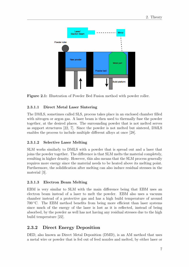


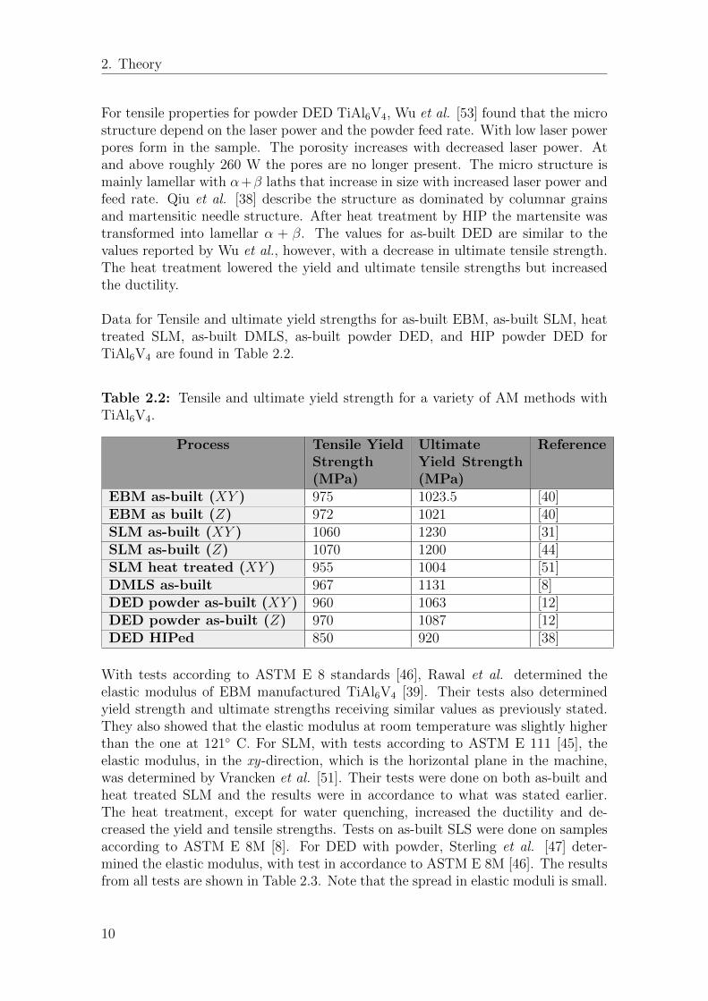


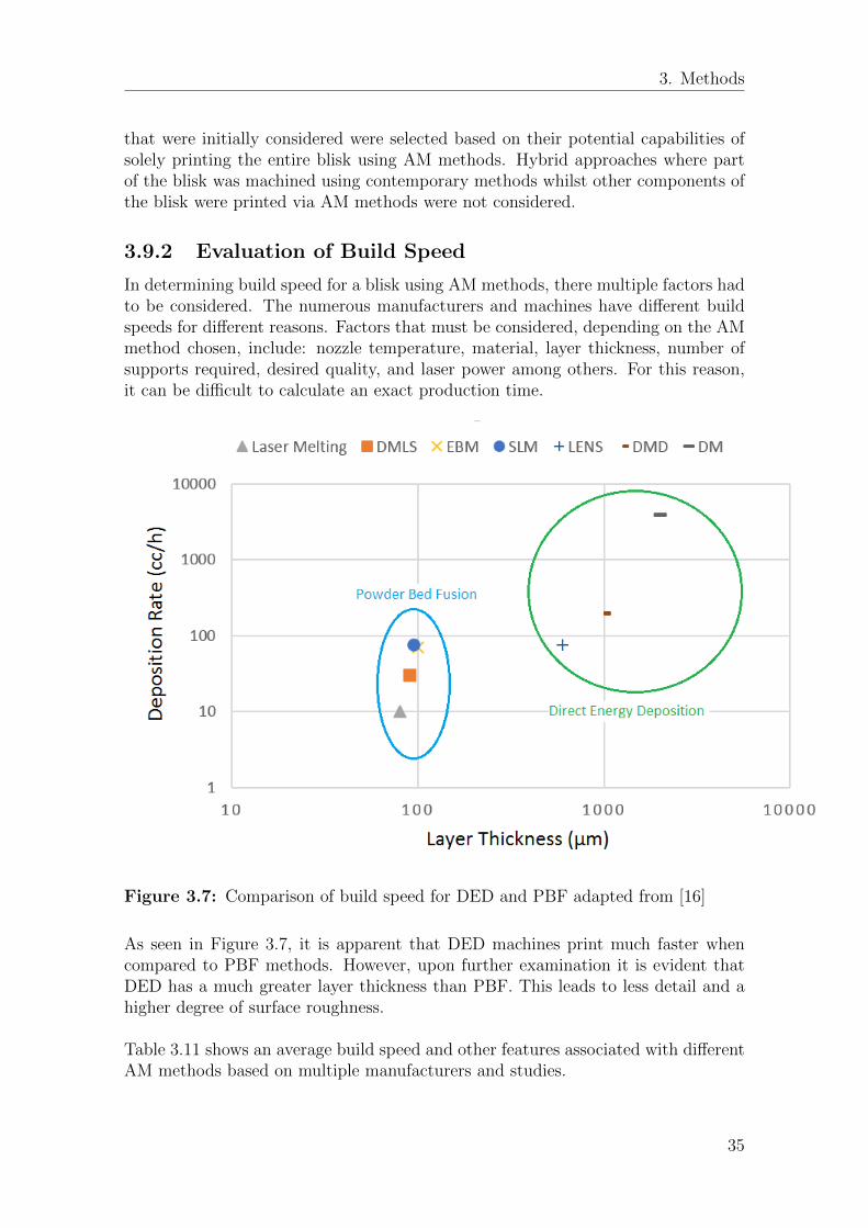


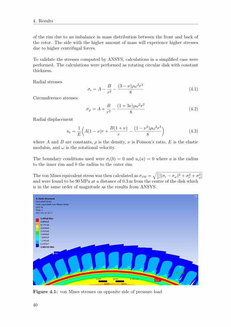


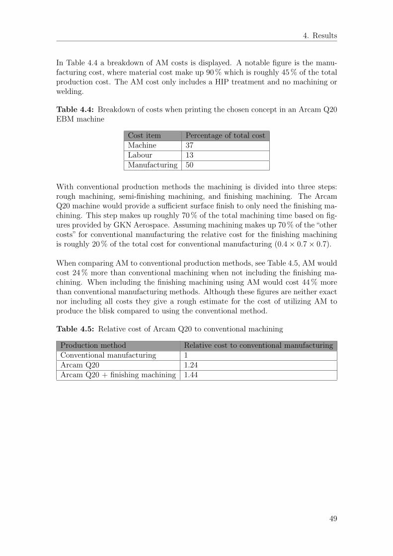


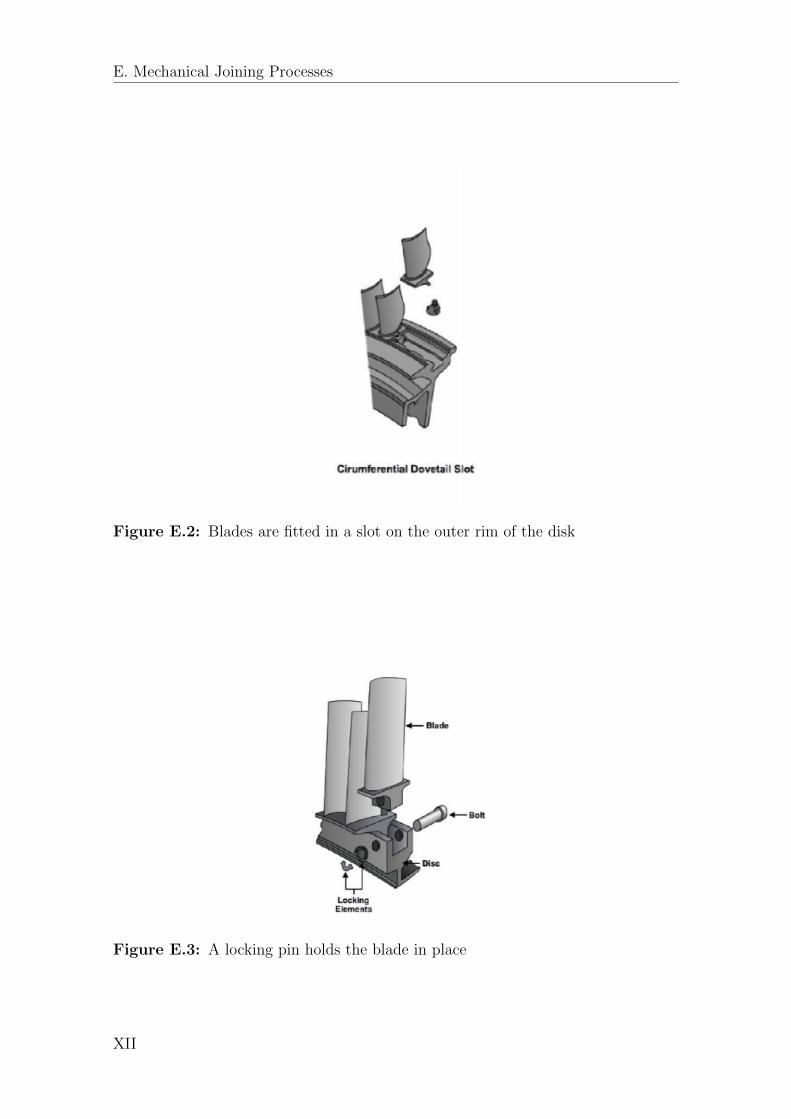


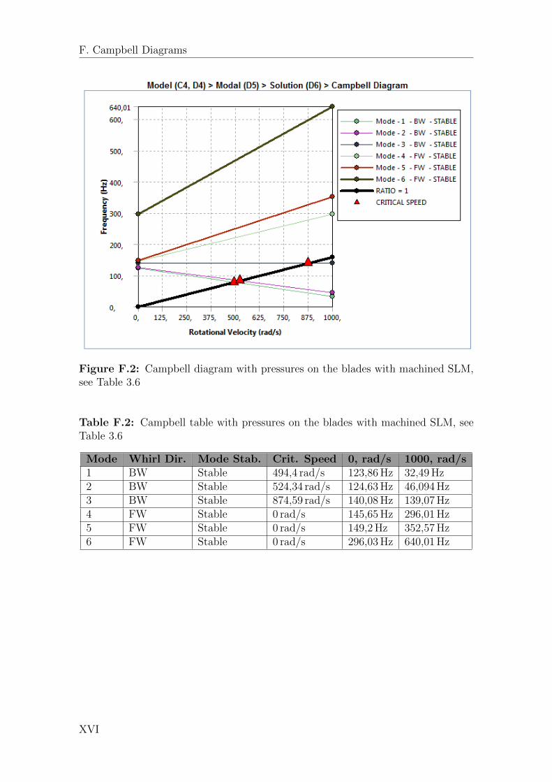


![Laser Polishing of Additive Manufactured 316L Stainless ...doras.dcu.ie/23212/1/Laser Polishing of Additive Manufactured 316L... · [1–8]. Compared with conventional subtractive](https://static.documents.pub/doc/80x56/5f57752d2f5d1e000425cf82/laser-polishing-of-additive-manufactured-316l-stainless-dorasdcuie232121laser.jpg)


