Resiliency Analysis of Cryocoolers Based LargeScale Superconducting Distribution Networks ofElectric Transport Systems
S. Telikapalli, P. Cheetham, C. H. Kim, and S. V. Pamidi
FAMU-FSU College of Electrical Engineering, Florida State UniversityCenter for Advanced Power Systems, Florida State UniversityTallahassee, FL 32310
ABSTRACT
The need for intelligent cryogenic circulation system designs to maintain the resiliency of high tempera-ture superconducting (HTS) power system components of large electric transportation systems is empha-sized. The requirements of cryocoolers characteristics to support electric transportation systems are dis-cussed. Thermal Network Models were developed and used to study the temperature profiles along thelength of HTS cables. The selection and location of cryocoolers and the design of cryogenic flow systemsare shown as critical to achieve overall system efficiency and resiliency. It is also shown that the flows ofelectricity and cryogenic fluid have to be designed together to incorporate the tightly couple the thermaland electrical aspects of HTS power system components. The use of two different cryocoolers and theirinfluence on the temperature profile of the electrical distribution network is discussed to emphasize theimportance of the choice of cryocoolers in achieving the necessary resiliency of electric transport systems.
INTRODUCTION
Rapid depletion of fossil fuels and increasing awareness of their adverse effects on the environmenthas accelerated the development of clean and sustainable transportation systems. There have been signifi-cant developments in reducing the dependence of transport systems on fossil fuels [1]. For automobileapplications, the most economical solution currently is to use batteries to store the energy to run the electricmotors. This is viable due to the low power density requirements of the automobile systems [2]. Depend-ing exclusively on energy storage is not feasible for the electrification of large transport systems such aselectric ships or electric aircraft. The challenge arises due to the large power ratings needed for the largetransportation systems. The estimated electric loads of an electric ship and an aircraft are 100 MW and40 MW, respectively [3].
For transport systems to be efficient and economical, the space and weight of the power system aremajor factors. Several studies have concluded that the optimal power distribution for electrification of largetransport systems is achieved by using medium voltage direct current (MVDC) distribution grids operatingbetween 10-20 kV [4]–[7]. To achieve the target power ratings of tens of MW using MVDC architecturewould require the current rating of the power distribution cables to be at several kA range. The use ofcopper or aluminum cables in such distribution systems would make the power systems prohibitively bulkyand heavy for large transport applications [8].
2High temperature superconducting (HTS) power cables have a significantly higher power densitycompared to their copper counterparts and have no electrical loss in DC applications. Therefore, they area natural choice to replace conventional copper technology in large MVDC power systems. It is envi-sioned that DC systems that incorporate HTS cables would have the reduced losses, smaller size, andlower weight MVDC distribution networks resulting in efficient overall power systems of large electrictransportation platforms [9].
Liquid nitrogen (LN2), the most commonly used cryogen for large scale demonstrations of HTStechnologies [10], is not suitable for large transport applications. This is due to the risk of over pressuriza-tion and asphyxiation associated with LN2 [11] and the limited operating temperature range of 65-77 K.Cryogens such as gaseous helium (GHe) and liquid hydrogen (LH2) are being explored as alternativecryogens. LH2 is being considered both as the fuel and the cryogen for electric aircraft by NASA in theN3-X, an all-electric superconducting aircraft [12], [13]. Airbus has announced a plan to use LH2 in nearfuture aircraft [14]. For electric ships, GHe is used as the cryogen to cool HTS motors, power cables, andother devices in a closed-loop circulation system [11], [15], [16]. The use of GHe as a cryogen allowslower operating temperatures, thus resulting in higher power densities in HTS cables than can be achievedusing LN2.
For electric transport applications, the reliability of the power system is crucial. The total failure ofelectric propulsion and essential systems must be avoided at all costs. Due to the deeply coupled nature ofcryogenic thermal and electrical systems in HTS devices, there is a need to understand the resiliency of thesystem from a cryogenic systems failure along with the electrical faults. The superconducting electricalsystem can perform only if the necessary cryogenic system is operational. The selection and design of thecryogenic system are thus of great importance, and both the electrical and cryogenic systems must bedesigned together. Failure in either the electrical and/or thermal system can affect the reliability and perfor-mance of the power system. Power systems must be designed to operate in the event of a device failure orduring the routine maintenance of the components.
Cryocoolers with attached heat exchangers are an integral part of the cryogenic system for GHecooled HTS power cables. The cryocoolers designed for transport systems have certain additional re-quirements compared to their terrestrial counterparts. They must be compact and lightweight to fully utilizethe benefits of HTS technology. The cryocoolers have to be highly efficient in their refrigeration cycles sothat the total loss in the system is considerably smaller than the total ohmic losses incurred when usingcopper cables. Finally, they should be easy to maintain and be capable of running for long durationsbetween the maintenance cycles.
Along with the generation of cooling power, additional challenges are involved in the distribution ofcooling power to the cryogen and circulation of cryogen in large HTS systems. There is a need for efficientdesigns for a heat exchanger that transfers the cooling power from the cold head of the cryocoolers to thecirculating cryogenic medium. High-speed gas circulators that generate a large volumetric flow and have alittle to no chance of failure in events of a sudden change of thermal loading have to be developed [10].
The type of cryocooler used plays an important role in the resiliency and the feasibility of the system.For example, if the envisioned lowest operating temperature that the HTS cables are subjected to isapproximately 70 K, we can make use of high efficiency and low maintenance reverse turbo Brayton (TB)cycle cryocoolers to achieve provide very high cooling power. TB refrigerators provide up to 40% Carnotefficiency and have a Mean Time Between Failure (MTBF) of 105,000 hours. The time between mainte-nance cycles is around 5 years. Commercially available TB coolers are capable of producing a coolingpower of 7.5 – 150 kW at 77 K [17].
For applications that require lower than 70 K operating temperature, the choice of the cryocoolerdepends on many factors including, the operating temperature range, the cooling power required, therefrigeration cycle, the efficiency of the refrigeration cycle, the size and weight of the cryocooler, thecommercial availability of cryocooler specific heat exchangers, the compatibility with gas cooled circula-tion systems, the time between maintenance cycles, the MTBF, and finally the cost of the cryocooler. Thechoice of cryocoolers also depends on the architecture of the ship or aircraft. It might be preferable to havemultiple smaller cryocoolers rather than one large cryocooler. This is to efficiently utilize all the spaceavailable on the platform. Stirling cycle and Gilford-McMahon cycle are some of the examples of refrig-eration cycles available in large capacity commercial cryocoolers. Both have a maintenance cycle of ap-
P#47
3proximately 10,000 hours and can produce between 350 and 400 W at 50 K, respectively [18], [19].High efficiency, very low-temperature free-piston Stirling cryocoolers for Navy HTS applications arebeing developed by Infinia Technology Corporation [20]. These cryocoolers are capable of producingover 400 W at 50 K and have a maintenance cycle of around 100,000 hours. These cryocoolers are soonto be commercially available. Finally, each type of cryocooler has its advantages and disadvantages. Thechoice of the cryocooler is application-specific and has to be made after careful consideration. For ourmodel, based on the estimates for heat load and expected operating temperatures, we have selectedSPC-4 and SPC-1 Stirling cryocoolers to understand the temperature profile of the HTS cables within anotional power system for electric transportation systems, using the electric ship as an example.
Another important factor to consider when incorporating HTS cables in transport systems is thatunlike in traditional power systems where cables often run point to point, electric transport applications arelikely to consist of multiple HTS cables connecting at common nodes. Using single cable terminations atevery junction would increase the weight and size of the HTS cable system significantly. There is a need todevelop “cryogenic nodes” that are capable of housing multiple HTS cables. A cryogenic node would havemultiple HTS cables and disconnect switches at the cryogenic temperature inside it. A cryogenic nodewould serve as the beginning and end of a cooling loop for multiple cables. Additionally, a cryogenic nodewould be capable of rerouting the flow of both electricity and cryogenic fluid independently. Developingand utilizing cryogenic nodes gives the opportunity for the cryogenic system to be optimized to achieveoverall system efficiency.
It is also necessary to ensure that the desired changes in operating current and associated heat loadsare accounted for by the cryogenic system without causing the HTS cable to quench. This is for both thenormal operation and contingency conditions. The contingency operation includes partial failures to boththe electrical and/or cryogenic systems. It is, therefore, necessary to also understand how to develop thecryogenic system in a power-dense manner whilst ensuring the failure within the cryogenic system does notaffect the power system. The resiliency in the cryogenic network of the power system has to be achievedat both the system level and device level.
This paper explores a notional shipboard power system rated for 100 MW and utilizing HTS cablesfor the main DC bus operating at 12 kV. The power system uses a radial fed cable architecture and zonalbased cryogenic system. The paper provides an overview of both the electrical and cryogenic systemsarchitectures and the development of thermal network models to estimate the required cooling power ofcryocoolers to enable the power system to be resilient and power-dense. The paper discusses the differ-ence in the temperature profiles of the system when using two different types of cryocoolers.
NOTIONAL MVDC MICROGRID INCORPORATING HTS CABLES
Cryogenic Node
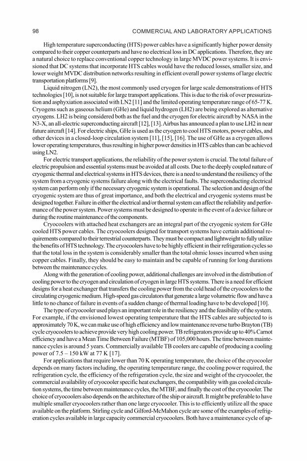
The notional power system developed for a 100 MW electric ship consists of eight cable cryostatseach approximately 100-m in length. Each cryostat houses 3 dipole HTS cables that are cooled by circulatingGHe. Each dipole cable terminates at a unique destination within the power system via a cryogenic node.The cryogenic node contains a thermal break as part of the system, which allows each cable section to becooled by different cooling loops if required. A schematic of the layout of one of the cryostats is shown inFigure 1.
Figure 1. Cryogenic nodes that can reroute the flow of electricity and cryogenic fluid.
COMMERCIAL AND LABORATORY APPLICATIONS 98
P#47
2High temperature superconducting (HTS) power cables have a significantly higher power densitycompared to their copper counterparts and have no electrical loss in DC applications. Therefore, they area natural choice to replace conventional copper technology in large MVDC power systems. It is envi-sioned that DC systems that incorporate HTS cables would have the reduced losses, smaller size, andlower weight MVDC distribution networks resulting in efficient overall power systems of large electrictransportation platforms [9].
Liquid nitrogen (LN2), the most commonly used cryogen for large scale demonstrations of HTStechnologies [10], is not suitable for large transport applications. This is due to the risk of over pressuriza-tion and asphyxiation associated with LN2 [11] and the limited operating temperature range of 65-77 K.Cryogens such as gaseous helium (GHe) and liquid hydrogen (LH2) are being explored as alternativecryogens. LH2 is being considered both as the fuel and the cryogen for electric aircraft by NASA in theN3-X, an all-electric superconducting aircraft [12], [13]. Airbus has announced a plan to use LH2 in nearfuture aircraft [14]. For electric ships, GHe is used as the cryogen to cool HTS motors, power cables, andother devices in a closed-loop circulation system [11], [15], [16]. The use of GHe as a cryogen allowslower operating temperatures, thus resulting in higher power densities in HTS cables than can be achievedusing LN2.
For electric transport applications, the reliability of the power system is crucial. The total failure ofelectric propulsion and essential systems must be avoided at all costs. Due to the deeply coupled nature ofcryogenic thermal and electrical systems in HTS devices, there is a need to understand the resiliency of thesystem from a cryogenic systems failure along with the electrical faults. The superconducting electricalsystem can perform only if the necessary cryogenic system is operational. The selection and design of thecryogenic system are thus of great importance, and both the electrical and cryogenic systems must bedesigned together. Failure in either the electrical and/or thermal system can affect the reliability and perfor-mance of the power system. Power systems must be designed to operate in the event of a device failure orduring the routine maintenance of the components.
Cryocoolers with attached heat exchangers are an integral part of the cryogenic system for GHecooled HTS power cables. The cryocoolers designed for transport systems have certain additional re-quirements compared to their terrestrial counterparts. They must be compact and lightweight to fully utilizethe benefits of HTS technology. The cryocoolers have to be highly efficient in their refrigeration cycles sothat the total loss in the system is considerably smaller than the total ohmic losses incurred when usingcopper cables. Finally, they should be easy to maintain and be capable of running for long durationsbetween the maintenance cycles.
Along with the generation of cooling power, additional challenges are involved in the distribution ofcooling power to the cryogen and circulation of cryogen in large HTS systems. There is a need for efficientdesigns for a heat exchanger that transfers the cooling power from the cold head of the cryocoolers to thecirculating cryogenic medium. High-speed gas circulators that generate a large volumetric flow and have alittle to no chance of failure in events of a sudden change of thermal loading have to be developed [10].
The type of cryocooler used plays an important role in the resiliency and the feasibility of the system.For example, if the envisioned lowest operating temperature that the HTS cables are subjected to isapproximately 70 K, we can make use of high efficiency and low maintenance reverse turbo Brayton (TB)cycle cryocoolers to achieve provide very high cooling power. TB refrigerators provide up to 40% Carnotefficiency and have a Mean Time Between Failure (MTBF) of 105,000 hours. The time between mainte-nance cycles is around 5 years. Commercially available TB coolers are capable of producing a coolingpower of 7.5 – 150 kW at 77 K [17].
For applications that require lower than 70 K operating temperature, the choice of the cryocoolerdepends on many factors including, the operating temperature range, the cooling power required, therefrigeration cycle, the efficiency of the refrigeration cycle, the size and weight of the cryocooler, thecommercial availability of cryocooler specific heat exchangers, the compatibility with gas cooled circula-tion systems, the time between maintenance cycles, the MTBF, and finally the cost of the cryocooler. Thechoice of cryocoolers also depends on the architecture of the ship or aircraft. It might be preferable to havemultiple smaller cryocoolers rather than one large cryocooler. This is to efficiently utilize all the spaceavailable on the platform. Stirling cycle and Gilford-McMahon cycle are some of the examples of refrig-eration cycles available in large capacity commercial cryocoolers. Both have a maintenance cycle of ap-
P#47
3proximately 10,000 hours and can produce between 350 and 400 W at 50 K, respectively [18], [19].High efficiency, very low-temperature free-piston Stirling cryocoolers for Navy HTS applications arebeing developed by Infinia Technology Corporation [20]. These cryocoolers are capable of producingover 400 W at 50 K and have a maintenance cycle of around 100,000 hours. These cryocoolers are soonto be commercially available. Finally, each type of cryocooler has its advantages and disadvantages. Thechoice of the cryocooler is application-specific and has to be made after careful consideration. For ourmodel, based on the estimates for heat load and expected operating temperatures, we have selectedSPC-4 and SPC-1 Stirling cryocoolers to understand the temperature profile of the HTS cables within anotional power system for electric transportation systems, using the electric ship as an example.
Another important factor to consider when incorporating HTS cables in transport systems is thatunlike in traditional power systems where cables often run point to point, electric transport applications arelikely to consist of multiple HTS cables connecting at common nodes. Using single cable terminations atevery junction would increase the weight and size of the HTS cable system significantly. There is a need todevelop “cryogenic nodes” that are capable of housing multiple HTS cables. A cryogenic node would havemultiple HTS cables and disconnect switches at the cryogenic temperature inside it. A cryogenic nodewould serve as the beginning and end of a cooling loop for multiple cables. Additionally, a cryogenic nodewould be capable of rerouting the flow of both electricity and cryogenic fluid independently. Developingand utilizing cryogenic nodes gives the opportunity for the cryogenic system to be optimized to achieveoverall system efficiency.
It is also necessary to ensure that the desired changes in operating current and associated heat loadsare accounted for by the cryogenic system without causing the HTS cable to quench. This is for both thenormal operation and contingency conditions. The contingency operation includes partial failures to boththe electrical and/or cryogenic systems. It is, therefore, necessary to also understand how to develop thecryogenic system in a power-dense manner whilst ensuring the failure within the cryogenic system does notaffect the power system. The resiliency in the cryogenic network of the power system has to be achievedat both the system level and device level.
This paper explores a notional shipboard power system rated for 100 MW and utilizing HTS cablesfor the main DC bus operating at 12 kV. The power system uses a radial fed cable architecture and zonalbased cryogenic system. The paper provides an overview of both the electrical and cryogenic systemsarchitectures and the development of thermal network models to estimate the required cooling power ofcryocoolers to enable the power system to be resilient and power-dense. The paper discusses the differ-ence in the temperature profiles of the system when using two different types of cryocoolers.
NOTIONAL MVDC MICROGRID INCORPORATING HTS CABLES
Cryogenic Node
The notional power system developed for a 100 MW electric ship consists of eight cable cryostatseach approximately 100-m in length. Each cryostat houses 3 dipole HTS cables that are cooled by circulatingGHe. Each dipole cable terminates at a unique destination within the power system via a cryogenic node.The cryogenic node contains a thermal break as part of the system, which allows each cable section to becooled by different cooling loops if required. A schematic of the layout of one of the cryostats is shown inFigure 1.
Figure 1. Cryogenic nodes that can reroute the flow of electricity and cryogenic fluid.
RESILIENCY ANALYSIS OF SUPERCONDUCTING NETWORKS 99
P#47
4Figure 1 shows the cryogenic node that has twelve current/terminal leads, six of these are closedduring the normal operation and the remaining six are closed only in case of a contingency when the HTScable has to operate at a higher current. There are multiple cryogenic disconnect switches housed insidethe cryogenic node. These disconnect switches act as a means to reroute the electrical power and also actas fault current limiters working along with the power electronics in the generator and the motor. It is worthnoting that, currently a cryogenic disconnect switch does not exist and has to be developed. Although usingswitchgear at cryogenic temperature introduces additional heat load into the cooling loop, it wouldconsiderably decrease the footprint of the system compared to using conventional circuit breakers andcable terminations to tap into the HTS cable. Additionally, having spare terminal leads will add additionalheat load into the cryogenic node even in regular operation. This additional heat seep into the cryogeniccooling loop is through conduction from copper terminal leads. Having the switchgear operating at cryogenictemperatures reduces the thermal gradient along the copper lead which reduces the heat load onto thecryogenic system as it allows the potential of two-stage cooling to be implemented when terminating anHTS cable to ambient. The remaining cryogenic nodes only have two terminal leads which connect toambient as this allows for simpler terminations and reduced heat loads compared to having all cablesterminate at each location.
Heat Loads Influencing the HTS Cable Systems
For each cryostat, it is necessary to understand all the heat loads that influence the temperaturegradient along its length. The heat loads on the cryostat are the ambient heat seep through the cryogenicnodes and along the length of the cryostat; the heat load introduced by the current leads; the heat load ofthe disconnect switches; and the ohmic losses at the cable joints. In electric transport applications a typicalcable section length is less than 100 m, and assuming a heat seep of 1 W/m, the heat load would be at most100 W [21]. This suggests that the majority of the heat load is produced at the cryogenic nodes. The heatload at a cryogenic node varies from 100 – 500 W, depending on the number of terminal leads, theoperating current, and the heat leak from ambient. The heat load at the disconnect switch is assumed to bea notional value of 5 W per switch.
Increasing/decreasing the operating current from the design current of the terminal lead will result inhigher than optimal heat loads because the current leads are typically optimized for minimum heat load atnormal operating current using the McFee process [22], [23]. It is therefore necessary to understand thepermissible operating currents of HTS cables. The flexible current rating of HTS cables means there is apotential for HTS cables to operate at higher current levels during peak load times or to mitigate failures ofanother HTS cable within the system. However, this is only possible if the additional heat load is handledby the cryogenic system. Additional heat load being introduced into the cryogenic system has the potentialto reduce the safety margin between the critical current and operating current of the HTS cable. One of ourprevious publications concluded the operation of HTS cables in parallel to keep the operating current ofthe system between 1-2 kA with adequate margin between operating and critical currents of the HTScable [24]. In that study, a single Stirling SPC-1 cryocooler was assumed to provide the cooling power toeach HTS cable section. Building upon the research we are investigating the ability to cool multiple HTScables in parallel as well as the possibility to decouple the electrical and thermal system from one anotherand have a zonal-based cryogenic cooling.
The architecture of the cable system causes an HTS cable to come across multiple cryogenic nodesthroughout its length. Aided by the long lengths of cables (approximately 100 m), the temperature gradientalong the length of the cable could be significant. A large temperature gradient is detrimental because thecritical current of a cable is dictated by its hottest point. In case of a contingency operation, where highercurrents are run through the cable to mitigate the loss of a cable/component, we need to make sure toconsider the temperature gradient to avoid the cable from quenching. Furthermore, the cooling loops haveto be designed in such a way that the temperature gradient along the length of a cable is minimized.
Notional Electrical Schematic of the Ship
A schematic of the electrical system of the ship is shown in Figure 2. As seen in Figure 2, each 25 MWgenerator (PGM 1 - 4) is dual wound and supplies two rectifiers rated for 25 MW each. This setup allowsthe entire current of the generator to be supplied through one of the cryostats if needed in case of failure of
P#47
5
a rectifier. HTS cables originating at cryogenic nodes at the rectifiers pass along the length of the ship andsupply power to loads spread across Zones 1-4. In this architecture, the electric propulsion is situated inzones 2 and 3. Accordingly, they have a higher load rating than zones 1 and 4. The electrical loadingsassumed for this model are 5, 45, 40 and 10 MW for Zones 1, 2, 3, and 4, respectively. The architecturewas built to have extreme resiliency and redundancy. It is envisioned that the power system can sustainfailures in generators, rectifiers, cables, and cooling systems without total loss of power to the loads. Thecable layout is symmetrical which means that a cable failure in an even number of cryostats will have similarresults to one another. The same is true for odd number cryostats. The electrical and the thermal schemat-ics were built simultaneously to ensure system-level redundancy in the cryogenic system and to fully utilizethe temperature-dependent critical current nature of HTS cables to add in additional redundancy in case offault on one of the cables or the components.
Figure 2. Notional electrical schematic of an electric ship.
COMMERCIAL AND LABORATORY APPLICATIONS 100
P#47
4Figure 1 shows the cryogenic node that has twelve current/terminal leads, six of these are closedduring the normal operation and the remaining six are closed only in case of a contingency when the HTScable has to operate at a higher current. There are multiple cryogenic disconnect switches housed insidethe cryogenic node. These disconnect switches act as a means to reroute the electrical power and also actas fault current limiters working along with the power electronics in the generator and the motor. It is worthnoting that, currently a cryogenic disconnect switch does not exist and has to be developed. Although usingswitchgear at cryogenic temperature introduces additional heat load into the cooling loop, it wouldconsiderably decrease the footprint of the system compared to using conventional circuit breakers andcable terminations to tap into the HTS cable. Additionally, having spare terminal leads will add additionalheat load into the cryogenic node even in regular operation. This additional heat seep into the cryogeniccooling loop is through conduction from copper terminal leads. Having the switchgear operating at cryogenictemperatures reduces the thermal gradient along the copper lead which reduces the heat load onto thecryogenic system as it allows the potential of two-stage cooling to be implemented when terminating anHTS cable to ambient. The remaining cryogenic nodes only have two terminal leads which connect toambient as this allows for simpler terminations and reduced heat loads compared to having all cablesterminate at each location.
Heat Loads Influencing the HTS Cable Systems
For each cryostat, it is necessary to understand all the heat loads that influence the temperaturegradient along its length. The heat loads on the cryostat are the ambient heat seep through the cryogenicnodes and along the length of the cryostat; the heat load introduced by the current leads; the heat load ofthe disconnect switches; and the ohmic losses at the cable joints. In electric transport applications a typicalcable section length is less than 100 m, and assuming a heat seep of 1 W/m, the heat load would be at most100 W [21]. This suggests that the majority of the heat load is produced at the cryogenic nodes. The heatload at a cryogenic node varies from 100 – 500 W, depending on the number of terminal leads, theoperating current, and the heat leak from ambient. The heat load at the disconnect switch is assumed to bea notional value of 5 W per switch.
Increasing/decreasing the operating current from the design current of the terminal lead will result inhigher than optimal heat loads because the current leads are typically optimized for minimum heat load atnormal operating current using the McFee process [22], [23]. It is therefore necessary to understand thepermissible operating currents of HTS cables. The flexible current rating of HTS cables means there is apotential for HTS cables to operate at higher current levels during peak load times or to mitigate failures ofanother HTS cable within the system. However, this is only possible if the additional heat load is handledby the cryogenic system. Additional heat load being introduced into the cryogenic system has the potentialto reduce the safety margin between the critical current and operating current of the HTS cable. One of ourprevious publications concluded the operation of HTS cables in parallel to keep the operating current ofthe system between 1-2 kA with adequate margin between operating and critical currents of the HTScable [24]. In that study, a single Stirling SPC-1 cryocooler was assumed to provide the cooling power toeach HTS cable section. Building upon the research we are investigating the ability to cool multiple HTScables in parallel as well as the possibility to decouple the electrical and thermal system from one anotherand have a zonal-based cryogenic cooling.
The architecture of the cable system causes an HTS cable to come across multiple cryogenic nodesthroughout its length. Aided by the long lengths of cables (approximately 100 m), the temperature gradientalong the length of the cable could be significant. A large temperature gradient is detrimental because thecritical current of a cable is dictated by its hottest point. In case of a contingency operation, where highercurrents are run through the cable to mitigate the loss of a cable/component, we need to make sure toconsider the temperature gradient to avoid the cable from quenching. Furthermore, the cooling loops haveto be designed in such a way that the temperature gradient along the length of a cable is minimized.
Notional Electrical Schematic of the Ship
A schematic of the electrical system of the ship is shown in Figure 2. As seen in Figure 2, each 25 MWgenerator (PGM 1 - 4) is dual wound and supplies two rectifiers rated for 25 MW each. This setup allowsthe entire current of the generator to be supplied through one of the cryostats if needed in case of failure of
P#47
5
a rectifier. HTS cables originating at cryogenic nodes at the rectifiers pass along the length of the ship andsupply power to loads spread across Zones 1-4. In this architecture, the electric propulsion is situated inzones 2 and 3. Accordingly, they have a higher load rating than zones 1 and 4. The electrical loadingsassumed for this model are 5, 45, 40 and 10 MW for Zones 1, 2, 3, and 4, respectively. The architecturewas built to have extreme resiliency and redundancy. It is envisioned that the power system can sustainfailures in generators, rectifiers, cables, and cooling systems without total loss of power to the loads. Thecable layout is symmetrical which means that a cable failure in an even number of cryostats will have similarresults to one another. The same is true for odd number cryostats. The electrical and the thermal schemat-ics were built simultaneously to ensure system-level redundancy in the cryogenic system and to fully utilizethe temperature-dependent critical current nature of HTS cables to add in additional redundancy in case offault on one of the cables or the components.
Figure 2. Notional electrical schematic of an electric ship.
RESILIENCY ANALYSIS OF SUPERCONDUCTING NETWORKS 101
P#47
6
Cryogenic Fluid Circulation System
The required cryogenic environment of the HTS system is maintained by multiple cooling loops thatstart at the cryocoolers located at the zonal switchboards of Zone 2 and Zone 3 on both the port andstarboard sides of the ship. Figure 3 and Table 1 show the cooling loops pertaining to HTS cables originat-ing from one generator. Due to the symmetrical nature of the system, understanding the cryogenic circula-tion system for one set of cables can be extended to the remaining three.
Figure 3. Cryogenic circulation system showing the cooling loops for most resilient operation.
Table 1. Cooling loops in central zones (2/3)
P#47
7Cryogenic node 1 (cooling loop 1 and 2), is located next to the rectifiers (ZP2-R1 and R2). This nodeconsists of 12 current leads, 6 normally open and 6 normally closed. In the first model, we have used oneSPC-1 cryocooler for each HTS cable dipole, and in the second model, we have assumed one SPC-4cryocooler per zone. As seen in Table 1, the cryogen flows to the HTS cable first and to the cryogenicnode next to make sure the temperature of the HTS cable remains low and is not influenced by the largeheat load introduced at the node.
Cryogenic nodes 2 and 3 (cooling loops 3-8) supply the cooling power to the cryogenic nodes andHTS cables that serve the zonal loads at the port and starboard sides of the craft. Nodes 2 and 3 have twocurrent leads each and similar to node 1 have one SPC-1 per node in the first case. For the second case,one SPC-4 serves both nodes.
Cryogenic node 4 (cooling loops 9 and 10) supply the cooling power to HTS cables and the cryo-genic node is situated in adjacent low load zones such as Zone 1 or Zone 4. These are the longest spans ofcables, with a length of about 57 m. The redundancy in this loop is not provided at this level, in case offailure of a cryogenic equipment or HTS cable in this cryostat, the loads in the zone are supplied through adifferent channel.
Cooling loops 11-14 are normally open. They are closed in case of a failure of the cryogenic circula-tion system that normally serves the cryogenic nodes 2 and 3 of the adjacent zone. This is to build addi-tional redundancy into zones 2 and 3 in case of failure of cooling systems. This is important as in ourarchitecture, the most essential loads such as propulsion and radar systems are located in Zones 2 and 3.
The model we have developed does not consider the difference in electrical and thermal time con-stants. Electrical time constants are in the ìs to ms timescales while the thermal time constant could beanywhere from a few seconds to a few minutes. However, this would not decrease the accuracy of themodel significantly when studying the response of the thermal system to electrical studies. The reason forthat is the built-in heat capacities of the system. Most cryogenic devices have a large heat capacity associ-ated with them and do not change their temperature instantaneously. To further increase the resiliency ofthe thermal systems to faults, we have previously looked at introducing a solid nitrogen buffer to the cableterminations, improving the operation time of the system after failure of a cryocooler to a maximum of90 mins [25]. Even without the buffer, the system engineer would have enough time to respond to the failure andredirect power as necessary before the cables quench. However, the major challenge is in real-time monitoringof the state of the system and to ensure the authenticity of the data obtained to the control unit.
MODEL RESULTS AND DISCUSSION
Figures 4 and 5 show the results of the Thermal Network Models using SPC-1 and SPC-4 Stirlingcryocoolers. The main purpose of these models is to aid in the system design process. These models act as
Figure 4. Temperature profile of the HTS cable system when using two SPC-1 Cryocoolers.
COMMERCIAL AND LABORATORY APPLICATIONS 102
P#47
6
Cryogenic Fluid Circulation System
The required cryogenic environment of the HTS system is maintained by multiple cooling loops thatstart at the cryocoolers located at the zonal switchboards of Zone 2 and Zone 3 on both the port andstarboard sides of the ship. Figure 3 and Table 1 show the cooling loops pertaining to HTS cables originat-ing from one generator. Due to the symmetrical nature of the system, understanding the cryogenic circula-tion system for one set of cables can be extended to the remaining three.
Figure 3. Cryogenic circulation system showing the cooling loops for most resilient operation.
Table 1. Cooling loops in central zones (2/3)
P#47
7Cryogenic node 1 (cooling loop 1 and 2), is located next to the rectifiers (ZP2-R1 and R2). This nodeconsists of 12 current leads, 6 normally open and 6 normally closed. In the first model, we have used oneSPC-1 cryocooler for each HTS cable dipole, and in the second model, we have assumed one SPC-4cryocooler per zone. As seen in Table 1, the cryogen flows to the HTS cable first and to the cryogenicnode next to make sure the temperature of the HTS cable remains low and is not influenced by the largeheat load introduced at the node.
Cryogenic nodes 2 and 3 (cooling loops 3-8) supply the cooling power to the cryogenic nodes andHTS cables that serve the zonal loads at the port and starboard sides of the craft. Nodes 2 and 3 have twocurrent leads each and similar to node 1 have one SPC-1 per node in the first case. For the second case,one SPC-4 serves both nodes.
Cryogenic node 4 (cooling loops 9 and 10) supply the cooling power to HTS cables and the cryo-genic node is situated in adjacent low load zones such as Zone 1 or Zone 4. These are the longest spans ofcables, with a length of about 57 m. The redundancy in this loop is not provided at this level, in case offailure of a cryogenic equipment or HTS cable in this cryostat, the loads in the zone are supplied through adifferent channel.
Cooling loops 11-14 are normally open. They are closed in case of a failure of the cryogenic circula-tion system that normally serves the cryogenic nodes 2 and 3 of the adjacent zone. This is to build addi-tional redundancy into zones 2 and 3 in case of failure of cooling systems. This is important as in ourarchitecture, the most essential loads such as propulsion and radar systems are located in Zones 2 and 3.
The model we have developed does not consider the difference in electrical and thermal time con-stants. Electrical time constants are in the ìs to ms timescales while the thermal time constant could beanywhere from a few seconds to a few minutes. However, this would not decrease the accuracy of themodel significantly when studying the response of the thermal system to electrical studies. The reason forthat is the built-in heat capacities of the system. Most cryogenic devices have a large heat capacity associ-ated with them and do not change their temperature instantaneously. To further increase the resiliency ofthe thermal systems to faults, we have previously looked at introducing a solid nitrogen buffer to the cableterminations, improving the operation time of the system after failure of a cryocooler to a maximum of90 mins [25]. Even without the buffer, the system engineer would have enough time to respond to the failure andredirect power as necessary before the cables quench. However, the major challenge is in real-time monitoringof the state of the system and to ensure the authenticity of the data obtained to the control unit.
MODEL RESULTS AND DISCUSSION
Figures 4 and 5 show the results of the Thermal Network Models using SPC-1 and SPC-4 Stirlingcryocoolers. The main purpose of these models is to aid in the system design process. These models act as
Figure 4. Temperature profile of the HTS cable system when using two SPC-1 Cryocoolers.
RESILIENCY ANALYSIS OF SUPERCONDUCTING NETWORKS 103
P#47
8
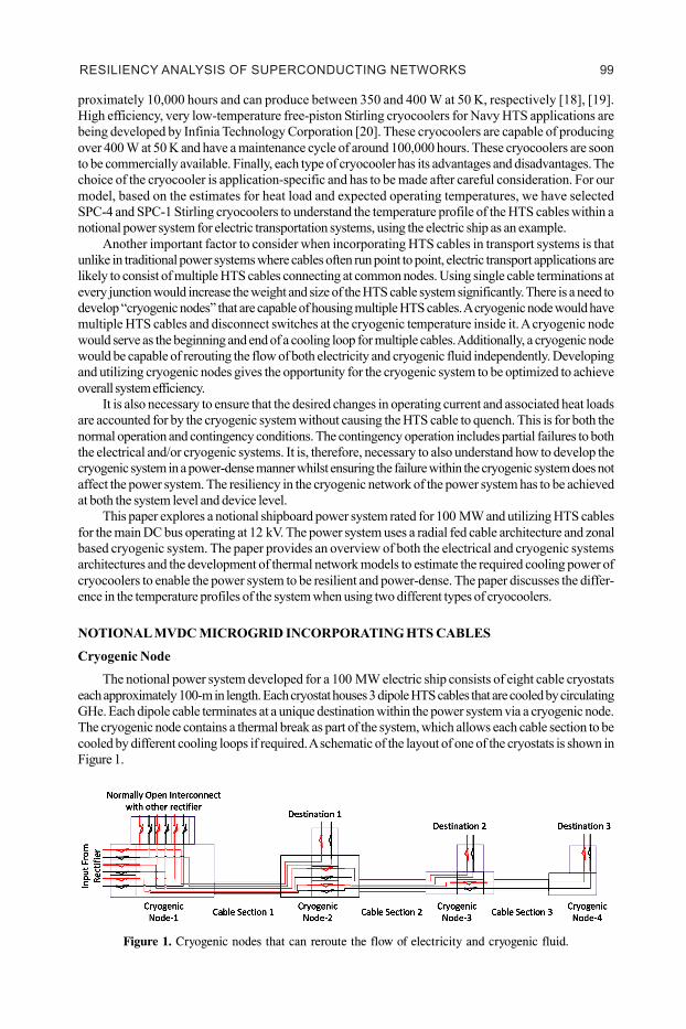
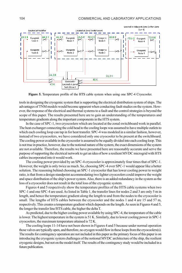
Figure 5. Temperature profile of the HTS cable system when using one SPC-4 Cryocooler.
tools in designing the cryogenic system that is supporting the electrical distribution system of ships. Theadvantages of TNM models would become apparent when conducting fault studies on the system. How-ever, the response of the electrical and thermal systems to a fault and the control strategies is beyond thescope of this paper. The results presented here are to gain an understanding of the temperatures andtemperature gradients along the important components in the HTS system.
In the case of SPC-1, two cryocoolers which are located at the zonal switchboard work in parallel.The heat exchanger connecting the cold head to the cooling loops was assumed to have multiple outlets towhich each cooling loop can tap in for heat transfer. SPC-4 was modeled in a similar fashion, however,instead of two cryocoolers, we have considered only one cryocooler to be present at the switchboard.The cooling power available in the cryocooler is assumed to be equally divided into each cooling loop. Thisis not true in practice, however, due to the notional nature of the system, the exact dimensions of the systemare not available. Therefore, the results we have presented here are reasonably accurate and serve thepurpose of supporting the electrical network to get an idea of how a resilient MVDC microgrid with HTScables incorporated into it would work.
The cooling power provided by an SPC-4 cryocooler is approximately four times that of SPC-1.However, the weight is only twice as much. So, choosing SPC-4 over SPC-1 would appear like a bettersolution. The reasoning behind choosing an SPC-1 cryocooler that has lower cooling power to weightratio, is that from a design standpoint accommodating two lighter cryocoolers could improve the weightand space distribution of the ship’s power system. Also, there is an added redundancy in the system as theloss of a cryocooler does not result in the total loss of the cryogenic system.
Figures 4 and 5 respectively show the temperature profiles of the HTS cable systems when twoSPC-1 and one SPC-4 are used. As listed in Table 1, the transfer lines for nodes 2 and 3 are only 5 m inlength, and hence the temperature gradient along the length to and from the nodes to the cryocooler issmall. The lengths of HTS cables between the cryocooler and the nodes 1 and 4 are 15 and 57 m,respectively. This creates a temperature gradient which depends on the length. As seen in Figures 4 and 5,the longer the transfer line/HTS cable, the higher the delta T.
As predicted, due to the higher cooling power available by using SPC-4, the temperature of the cableis lower. The highest temperature in the system is 51 K. Similarly, due to lower cooling power in SPC-1cryocoolers, the maximum temperature attained is 72 K.
The cooling loops 11-14 have not been shown in Figures 4 and 5 because under normal operationthose valves are typically open, and therefore, no cryogen would flow in these loops from the cryocoolers(s).The results for contingency operation are not included in this paper as the primary focus of this paper is onintroducing the cryogenic system challenges of the notional MVDC architecture of the ship, the resilientcryogenic designs, but not on the model itself. The results of the contingency study would be included in afuture publication.
P#47
9The goal for this work was to design a cryogenic circulation system that would keep the temperatureprofile of the system under 77 K under both normal operation and contingency operations. The resultsfrom the model show that under normal operation the use of any cryocoolers configuration would maintainthe desired temperature of the system.
As part of our ongoing research on this topic, we plan to use the models created in this paper to betterunderstand how temperature variation along the HTS cables changes for contingency operations. Additionalstudies to be performed also include understanding how the operating temperature of the HTS cable caninfluence the number of HTS conductors required per cable. Reducing the number of HTS conductors isone potential strategy to reduce the cost of the HTS power system due to the inherently high cost of HTSconductor.
ACKNOWLEDGMENT
This work was supported by the Office of Naval Research (ONR). Grant number N00014-18-1-2693 and N00014-16-1-2956
REFERENCES
[1] A. Tintelecan, A. Constantinescu-Dobra, and C. Martis, “LCA Indicators in Electric Vehicles Environ-mental Impact Assessment,” 2019 Electr. Veh. Int. Conf. EV 2019, 2019, doi: 10.1109/EV.2019.8892893.
[2] A. Ajanovic and R. Haas, “An economic, ecological and energetic assessment of battery electric,hybrid and fuel cell cars,” Asia-Pacific Power Energy Eng. Conf. APPEEC, no. 3, pp. 4–7, 2013, doi:10.1109/APPEEC.2013.6837311.
[3] S. Satyanarayana, “Florida State University Libraries Combined Electrical and Thermal Models forIntegrated Cryogenic Systems of Multiple Superconducting Power Devices,” 2018.
[4] G. Bathurst, G. Hwang, and L. Tejwani, “MVDC-the new technology for distribution networks,” IETSemin. Dig., vol. 2015, no. CP654, pp. 1–5, 2015, doi: 10.1049/cp.2015.0037.
[5] Z. J. Shen, G. Sabui, Z. Miao, and Z. Shuai, “Wide-bandgap solid-state circuit breakers for DC powersystems: Device and circuit considerations,” IEEE Trans. Electron Devices, vol. 62, no. 2, pp. 294–300, 2015, doi: 10.1109/TED.2014.2384204.
[6] G. L. Kusic, G. F. Reed, J. Svensson, and Z. Wang, “A case for medium voltage DC for distributioncircuit applications,” 2011 IEEE/PES Power Syst. Conf. Expo. PSCE 2011, pp. 1–7, 2011, doi: 10.1109/PSCE.2011.5772478.
[7] N. Doerry and John V. Amy Jr., “Design Considerations for a Reference MVDC Power System,”Naturwissenschaften, vol. 30, no. 16, p. 240, 2015, doi: 10.1007/BF01486360.
[8] P. A. Klaudy and J. Gerhold, “Trials,” vol. M, no. 3, 1983.
[9] R. E. Hebner, A. L. Gattozzi, S. M. Strank, S. P. Pish, and J. D. Herbst, “Electrical and thermal systemconsiderations for MVDC superconducting distribution on navy ships,” 2017 IEEE Electr. Sh. Technol.Symp. ESTS 2017, pp. 592–597, 2017, doi: 10.1109/ESTS.2017.8069342.
[10] C. H. Kim, J. Kim, and S. V Pamidi, “Cryogenic Thermal Studies on Cryocooler-Based Helium Circu-lation System for Gas Cooled Superconducting Power Devices,” Cryocoolers 18, ICC Press, Boulder,CO (2014), pp. 504–513.
[11] P. Cheetham, W. Kim, C. H. Kim, L. Graber, H. Rodrigo, and S. Pamidi, “Enhancement of DielectricStrength of Cryogenic Gaseous Helium by Addition of Small Mol% Hydrogen,” IEEE Trans. Appl.Supercond., vol. 27, no. 4, pp. 1–5, Jun. 2017, doi: 10.1109/TASC.2016.2642539.
[12] M. J. Armstrong et al., Architecture, Voltage, and Components for a Turboelectric DistributedPropulsion Electric Grid(AVC-TeDP), no. July. 2015.
[13] K. Davies, P. Norman, C. Jones, S. Galloway, and M. Husband, “A review of Turboelectric DistributedPropulsion technologies for N+3 aircraft electrical systems,” 2013, doi: 10.1109/UPEC.2013.6714885.
[14] Cheetham Peter, S. Telikapalli, C. H. Kim, and S. Pamidi, “A Comprehensive Guide to Superconductiv-ity - Chapter 1 - Superconducting Power Devices for the Electrification of Transportation,” in A Com-prehensive Guide to Superconductivity, 2020.
COMMERCIAL AND LABORATORY APPLICATIONS 104
P#47
8
Figure 5. Temperature profile of the HTS cable system when using one SPC-4 Cryocooler.
tools in designing the cryogenic system that is supporting the electrical distribution system of ships. Theadvantages of TNM models would become apparent when conducting fault studies on the system. How-ever, the response of the electrical and thermal systems to a fault and the control strategies is beyond thescope of this paper. The results presented here are to gain an understanding of the temperatures andtemperature gradients along the important components in the HTS system.
In the case of SPC-1, two cryocoolers which are located at the zonal switchboard work in parallel.The heat exchanger connecting the cold head to the cooling loops was assumed to have multiple outlets towhich each cooling loop can tap in for heat transfer. SPC-4 was modeled in a similar fashion, however,instead of two cryocoolers, we have considered only one cryocooler to be present at the switchboard.The cooling power available in the cryocooler is assumed to be equally divided into each cooling loop. Thisis not true in practice, however, due to the notional nature of the system, the exact dimensions of the systemare not available. Therefore, the results we have presented here are reasonably accurate and serve thepurpose of supporting the electrical network to get an idea of how a resilient MVDC microgrid with HTScables incorporated into it would work.
The cooling power provided by an SPC-4 cryocooler is approximately four times that of SPC-1.However, the weight is only twice as much. So, choosing SPC-4 over SPC-1 would appear like a bettersolution. The reasoning behind choosing an SPC-1 cryocooler that has lower cooling power to weightratio, is that from a design standpoint accommodating two lighter cryocoolers could improve the weightand space distribution of the ship’s power system. Also, there is an added redundancy in the system as theloss of a cryocooler does not result in the total loss of the cryogenic system.
Figures 4 and 5 respectively show the temperature profiles of the HTS cable systems when twoSPC-1 and one SPC-4 are used. As listed in Table 1, the transfer lines for nodes 2 and 3 are only 5 m inlength, and hence the temperature gradient along the length to and from the nodes to the cryocooler issmall. The lengths of HTS cables between the cryocooler and the nodes 1 and 4 are 15 and 57 m,respectively. This creates a temperature gradient which depends on the length. As seen in Figures 4 and 5,the longer the transfer line/HTS cable, the higher the delta T.
As predicted, due to the higher cooling power available by using SPC-4, the temperature of the cableis lower. The highest temperature in the system is 51 K. Similarly, due to lower cooling power in SPC-1cryocoolers, the maximum temperature attained is 72 K.
The cooling loops 11-14 have not been shown in Figures 4 and 5 because under normal operationthose valves are typically open, and therefore, no cryogen would flow in these loops from the cryocoolers(s).The results for contingency operation are not included in this paper as the primary focus of this paper is onintroducing the cryogenic system challenges of the notional MVDC architecture of the ship, the resilientcryogenic designs, but not on the model itself. The results of the contingency study would be included in afuture publication.
P#47
9The goal for this work was to design a cryogenic circulation system that would keep the temperatureprofile of the system under 77 K under both normal operation and contingency operations. The resultsfrom the model show that under normal operation the use of any cryocoolers configuration would maintainthe desired temperature of the system.
As part of our ongoing research on this topic, we plan to use the models created in this paper to betterunderstand how temperature variation along the HTS cables changes for contingency operations. Additionalstudies to be performed also include understanding how the operating temperature of the HTS cable caninfluence the number of HTS conductors required per cable. Reducing the number of HTS conductors isone potential strategy to reduce the cost of the HTS power system due to the inherently high cost of HTSconductor.
ACKNOWLEDGMENT
This work was supported by the Office of Naval Research (ONR). Grant number N00014-18-1-2693 and N00014-16-1-2956
REFERENCES
[1] A. Tintelecan, A. Constantinescu-Dobra, and C. Martis, “LCA Indicators in Electric Vehicles Environ-mental Impact Assessment,” 2019 Electr. Veh. Int. Conf. EV 2019, 2019, doi: 10.1109/EV.2019.8892893.
[2] A. Ajanovic and R. Haas, “An economic, ecological and energetic assessment of battery electric,hybrid and fuel cell cars,” Asia-Pacific Power Energy Eng. Conf. APPEEC, no. 3, pp. 4–7, 2013, doi:10.1109/APPEEC.2013.6837311.
[3] S. Satyanarayana, “Florida State University Libraries Combined Electrical and Thermal Models forIntegrated Cryogenic Systems of Multiple Superconducting Power Devices,” 2018.
[4] G. Bathurst, G. Hwang, and L. Tejwani, “MVDC-the new technology for distribution networks,” IETSemin. Dig., vol. 2015, no. CP654, pp. 1–5, 2015, doi: 10.1049/cp.2015.0037.
[5] Z. J. Shen, G. Sabui, Z. Miao, and Z. Shuai, “Wide-bandgap solid-state circuit breakers for DC powersystems: Device and circuit considerations,” IEEE Trans. Electron Devices, vol. 62, no. 2, pp. 294–300, 2015, doi: 10.1109/TED.2014.2384204.
[6] G. L. Kusic, G. F. Reed, J. Svensson, and Z. Wang, “A case for medium voltage DC for distributioncircuit applications,” 2011 IEEE/PES Power Syst. Conf. Expo. PSCE 2011, pp. 1–7, 2011, doi: 10.1109/PSCE.2011.5772478.
[7] N. Doerry and John V. Amy Jr., “Design Considerations for a Reference MVDC Power System,”Naturwissenschaften, vol. 30, no. 16, p. 240, 2015, doi: 10.1007/BF01486360.
[8] P. A. Klaudy and J. Gerhold, “Trials,” vol. M, no. 3, 1983.
[9] R. E. Hebner, A. L. Gattozzi, S. M. Strank, S. P. Pish, and J. D. Herbst, “Electrical and thermal systemconsiderations for MVDC superconducting distribution on navy ships,” 2017 IEEE Electr. Sh. Technol.Symp. ESTS 2017, pp. 592–597, 2017, doi: 10.1109/ESTS.2017.8069342.
[10] C. H. Kim, J. Kim, and S. V Pamidi, “Cryogenic Thermal Studies on Cryocooler-Based Helium Circu-lation System for Gas Cooled Superconducting Power Devices,” Cryocoolers 18, ICC Press, Boulder,CO (2014), pp. 504–513.
[11] P. Cheetham, W. Kim, C. H. Kim, L. Graber, H. Rodrigo, and S. Pamidi, “Enhancement of DielectricStrength of Cryogenic Gaseous Helium by Addition of Small Mol% Hydrogen,” IEEE Trans. Appl.Supercond., vol. 27, no. 4, pp. 1–5, Jun. 2017, doi: 10.1109/TASC.2016.2642539.
[12] M. J. Armstrong et al., Architecture, Voltage, and Components for a Turboelectric DistributedPropulsion Electric Grid(AVC-TeDP), no. July. 2015.
[13] K. Davies, P. Norman, C. Jones, S. Galloway, and M. Husband, “A review of Turboelectric DistributedPropulsion technologies for N+3 aircraft electrical systems,” 2013, doi: 10.1109/UPEC.2013.6714885.
[14] Cheetham Peter, S. Telikapalli, C. H. Kim, and S. Pamidi, “A Comprehensive Guide to Superconductiv-ity - Chapter 1 - Superconducting Power Devices for the Electrification of Transportation,” in A Com-prehensive Guide to Superconductivity, 2020.
RESILIENCY ANALYSIS OF SUPERCONDUCTING NETWORKS 105
P#47
10[15] S. S. Kalsi, “HTS ship propulsion motors,” 2004, doi: 10.1109/pes.2004.1373238.
[16] M. J. Gouge, J. A. Demko, P. W. Fisher, C. A. Foster, J. W. Lue, J. P. Stovall, U. Sinha, J. Armstrong,R. L. Hughey, D. Lindsay, and J. Tolbert, “Development and testing of HTS cables and terminations atORNL,” IEEE Trans. Appl. Supercond., vol. 11, no. 1, pp. 2341-2354, 2001.
[20] J. G. Schreiber, “Developmental considerations on the free-piston stirling power converter for use inspace,” Collect. Tech. Pap. - 4th Int. Energy Convers. Eng. Conf., vol. 1, no. May, pp. 157–183,2006, doi: 10.2514/6.2006-4015.
[21] Nexans, “CRYOFLEX ® Transfer Lines for Liquid Gases,” 2012. .
[22] L. Bromberg, P. C. Michael, J. V. Minervini, and C. Miles, “Current lead optimization for cryogenicoperation at intermediate temperatures,” AIP Conf. Proc., vol. 1218, no. 2010, pp. 577–584, 2010, doi:10.1063/1.3422405.
[23] R. McFee, “Optimum input leads for cryogenic apparatus,” Rev. Sci. Instrum., vol. 30, no. 2, pp. 98–102, 1959, doi: 10.1063/1.1716499.
[24] S. Telikapalli, P. Cheetham, C. H. Kim, and S. V. Pamidi, “Power Dense HTS Cable Microgrids –Designs for Contingencies and Resiliency (Submitted),” 2020.
[25] S. Satyanarayana, Z. Zhang, C. H. Kim, and S. Pamidi, “Models for Design and Analysis of Supercon-ducting Power Systems Cooled with Cryocoolers,” Cryocoolers 20, ICC Press, Boulder, CO (2018),pp. 427–437.
P#63
1
Space Cryogenic Circulator
D. Frank, A.D. Ruiz, M. Guzinski, E. Roth, V. Mistry,H. Yengoyan, J. R. Olson
Lockheed Martin SpacePalo Alto, CA. 94304
ABSTRACT
Circulation of cryogenic fluid is a critical technology for cryogenic propellent storage, where it isimportant to cool the large surface area of the cryogenic storage tank. Furthermore, cryogenic circulationcan enable remote cooling of sensitive instruments with low exported vibration by isolating the instrumentfrom the cryocooler with flexible coolant lines.
Lockheed Martin Space has developed a 1.4 kg cryogenic circulator based on a modified pulse tubecryocooler compressor. Lockheed Martin pulse tube compressors have previously operated at cryogenictemperatures as low as 125 K.1 With Lockheed Martin internal research and development funding, aTRL 6 Mini compressor was retrofitted with newly designed check valves which rectify the oscillating flow.This circulator was tested at ambient temperature, and the measured flow is equal to the piston sweptvolume times the drive frequency, as expected. The measured flow exceeded 3 standard liters per secondhelium flow with 90% motor efficiency.
Testing at cryogenic temperature was also performed, and the circulator performed without problemsat 90 K. Quantitative testing was not possible because neither the flow meter nor the piston positionsensors work at cryogenic temperatures, but some results are presented. These results indicate this cryo-genic circulator has sufficient flow to provide 50 W of remote cooling at 90 K with reasonably smallthermal gradients.
INTRODUCTION
Cold gas circulation provides remote cooling when the circulating gas is colder than the temperatureof the object being cooled. The available heat lift is Q = m CP ÓT where m is the mass flow rate in g/s, CP
is the specific heat in J/gK and ÓT is the temperature difference in K between the outlet and inlet temperatureof the circulating gas after heat is extracted from the cryogenic device. An efficient cryogenic circulatorrequires high mass flow which minimizes ÓT.
This paper describes the development of a cold gas circulator utilizing the space grade compressorand motor modules from a Lockheed Martin Mini cryocooler,2 with an added pair of check valves toproduce a circulating cold gas flow for remote cooling. The objective of the initial work in 2019 was todemonstrate the feasibility of the hardware configuration, while the objective of the 2020 follow-on workwas to achieve a technology readiness level (TRL) of five and demonstrate end-to-end performance of theremote cooling loop. The 2019 effort utilized an existing TRL 6 compressor with a separate external checkvalve assembly, while the 2020 effort designed and built a dedicated space-configuration circulator withintegrated check valves.