Resolving Scale Ambiguity Via XSlit Aspect Ratio Analysis Wei Yang 1 Haiting Lin 1 Sing Bing Kang 2 Jingyi Yu 1,3 1 University of Delaware {wyangcs,haiting}@udel.edu 2 Microsoft Research [email protected]3 ShanghaiTech University [email protected]Abstract In perspective cameras, images of a frontal-parallel 3D object preserve its aspect ratio invariant to its depth. Such an invariance is useful in photography but is unique to per- spective projection. In this paper, we show that alterna- tive non-perspective cameras such as the crossed-slit or XS- lit cameras exhibit a different depth-dependent aspect ra- tio (DDAR) property that can be used to 3D recovery. We first conduct a comprehensive analysis to characterize D- DAR, infer object depth from its AR, and model recoverable depth range, sensitivity, and error. We show that repeated shape patterns in real Manhattan World scenes can be used for 3D reconstruction using a single XSlit image. We also extend our analysis to model slopes of lines. Specifically, parallel 3D lines exhibit depth-dependent slopes (DDS) on their images which can also be used to infer their depth- s. We validate our analyses using real XSlit cameras, XSlit panoramas, and catadioptric mirrors. Experiments show that DDAR and DDS provide important depth cues and en- able effective single-image scene reconstruction. 1. Introduction A single perspective image exhibits scale ambiguity: 3D objects of difference sizes can have images of an identical size under perspective projection, as shown in Fig. 1. In photography and architecture, the forced perspective tech- nique employs this optical illusion to make an object ap- pear farther away, closer, larger or smaller than its actual size while preserving the aspect ratio. Fig. 2 shows an ex- ample in the film “The Lord of the Rings” where characters apparently standing next to each other would be displaced by several feet in depth from the camera. For computer vi- sion, however, such an invariance provides little help, if not harm, to scene reconstruction. Prior approaches on resolving the scale ambiguity range from imposing shape priors [3, 10], extracting local de- scriptors [16] to analyzing the vanishing points [13]. In this paper, we approach the problem from a different an- gle: we analyze aspect ratio changes of an object with re- Object XSlit Pinhole 17 cm 47 cm Depth CoP Slit 1 Slit 2 Sensor Sensor Figure 1: Images of the same object lying at different depths have an identical aspect ratio (AR) in a perspective camera (Top) but have very different ARs in an XSlit image (Bot- tom). spect to its depth. Consider a frontal-parallel rectangle R of size s h × s v located d away from the sensor and d>f where f is the camera’s focal length. Under perspective projection, its image is an rectangle R ′ similar to R of size [s ′ h ,s ′ v ]= f d−f [s h ,s v ]. This implies that the aspect ratio r = s v /s h of R and R ′ remain the same. The property can termed as aspect-ratio invariance (ARI). ARI is an im- portant property of perspective projection. ARI, however, no longer holds under non-centric projections, exhibiting depth-dependent aspect-ratio (DDAR). In this paper, we explore DDAR in a special type of non- centric cameras called the crossed-slit or XSlit camera [29]. Earlier work in XSlit imaging includes the pushbroom cam- era used in satellite imaging and XSlit panoramas by stitch- ing a sequence of perspective images. The General Lin- ear Camera theory [28] has shown that the XSlit camera is generic enough to describe a broad range of non-centric cameras. In fact, pushbroom, orthographic and perspective cameras can all be viewed as special XSlit entities. Geo- metrically, an XSlit camera collects rays that simultaneous- ly pass through two oblique (neither parallel nor coplanar) slits in 3D space, in contrast to a pinhole camera whose rays 3424
Transcript
Resolving Scale Ambiguity Via XSlit Aspect Ratio Analysis
Wei Yang1 Haiting Lin1 Sing Bing Kang2 Jingyi Yu1,3
In perspective cameras, images of a frontal-parallel 3D
object preserve its aspect ratio invariant to its depth. Such
an invariance is useful in photography but is unique to per-
spective projection. In this paper, we show that alterna-
tive non-perspective cameras such as the crossed-slit or XS-
lit cameras exhibit a different depth-dependent aspect ra-
tio (DDAR) property that can be used to 3D recovery. We
first conduct a comprehensive analysis to characterize D-
DAR, infer object depth from its AR, and model recoverable
depth range, sensitivity, and error. We show that repeated
shape patterns in real Manhattan World scenes can be used
for 3D reconstruction using a single XSlit image. We also
extend our analysis to model slopes of lines. Specifically,
parallel 3D lines exhibit depth-dependent slopes (DDS) on
their images which can also be used to infer their depth-
s. We validate our analyses using real XSlit cameras, XSlit
panoramas, and catadioptric mirrors. Experiments show
that DDAR and DDS provide important depth cues and en-
able effective single-image scene reconstruction.
1. Introduction
A single perspective image exhibits scale ambiguity: 3D
objects of difference sizes can have images of an identical
size under perspective projection, as shown in Fig. 1. In
photography and architecture, the forced perspective tech-
nique employs this optical illusion to make an object ap-
pear farther away, closer, larger or smaller than its actual
size while preserving the aspect ratio. Fig. 2 shows an ex-
ample in the film “The Lord of the Rings” where characters
apparently standing next to each other would be displaced
by several feet in depth from the camera. For computer vi-
sion, however, such an invariance provides little help, if not
harm, to scene reconstruction.
Prior approaches on resolving the scale ambiguity range
from imposing shape priors [3, 10], extracting local de-
scriptors [16] to analyzing the vanishing points [13]. In
this paper, we approach the problem from a different an-
gle: we analyze aspect ratio changes of an object with re-
Object
XSlit
Pinhole
17 cm 47 cm Depth
CoP
Slit 1 Slit 2Sensor
Sensor
Figure 1: Images of the same object lying at different depths
have an identical aspect ratio (AR) in a perspective camera
(Top) but have very different ARs in an XSlit image (Bot-
tom).
spect to its depth. Consider a frontal-parallel rectangle R
of size sh × sv located d away from the sensor and d > fwhere f is the camera’s focal length. Under perspective
projection, its image is an rectangle R′ similar to R of size
[s′h, s′
v] =f
d−f[sh, sv]. This implies that the aspect ratio
r = sv/sh of R and R′ remain the same. The property
can termed as aspect-ratio invariance (ARI). ARI is an im-
portant property of perspective projection. ARI, however,
no longer holds under non-centric projections, exhibiting
depth-dependent aspect-ratio (DDAR).
In this paper, we explore DDAR in a special type of non-
centric cameras called the crossed-slit or XSlit camera [29].
Earlier work in XSlit imaging includes the pushbroom cam-
era used in satellite imaging and XSlit panoramas by stitch-
ing a sequence of perspective images. The General Lin-
ear Camera theory [28] has shown that the XSlit camera
is generic enough to describe a broad range of non-centric
cameras. In fact, pushbroom, orthographic and perspective
cameras can all be viewed as special XSlit entities. Geo-
metrically, an XSlit camera collects rays that simultaneous-
ly pass through two oblique (neither parallel nor coplanar)
slits in 3D space, in contrast to a pinhole camera whose rays
3424
Figure 2: The perspective trick used in the movie “The Lord
of the Rings”.
pass through a common 3D point. Ye et al.[27] has further
proposed a practical realization by relaying a pair of cylin-
drical lenses coupled with slit-shaped apertures.
We show that the XSlit camera exhibits DDAR that can
help resolve scale ambiguity. Consider two 3D rectangles of
an identical size lying at different depth with their images
being R1 and R2 respectively. Different from the pinhole
case, the AR of R1 and R2 will be different, as shown in
Fig. 1. We first develop a comprehensive analysis to char-
acterize DDAR in the XSlit camera. This derivation leads
to a simple but effective graph-cut based scheme to recov-
er object depths from a single XSlit image and an effective
formulation to model recoverable depth range, sensitivity,
and errors. In particular, we show how to exploit repeated
shape patterns exhibiting in real Manhattan World scenes to
conduct 3D reconstruction.
Our DDAR analysis can further be extended to model
the slopes of lines. Specifically, for parallel 3D lines of a
common direction, we show that as far as the direction is d-
ifferent from both slits, their projections will exhibit depth-
dependent slopes or DDS, i.e., the projected 2D lines will
have different slopes depending on their depths. DDS and
DDAR can be combined to further improve 3D reconstruc-
tion accuracy. We validate our theories and algorithms on
both synthetic and real data. For real scenes, we experi-
ment on different types of XSlit images including the ones
captured by the XSlit lens [27] and synthesized as stitched
panoramas [21]. In addition, our scheme can be applied to
catadioptric mirrors by modeling reflections off the mirrors
as XSlit images. Experiments show that DDAR and DDS
provide important depth cues and enable effective single-
image scene reconstruction.
2. Related Work
Our work is most related to Manhattan World reconstruc-
tion and non-centric imaging.
A major task of computer vision is to infer 3D geome-
try of scenes using as fewer images as possible. Tremen-
dous efforts have focused on recovering a special class of
scene called the Manhattan World (MW) [4]. MW is com-
posed of repeated planar surfaces and parallel lines aligned
with three mutually orthogonal principal axes and fits well
to many man-made (interior/exterior) environments. Under
the MW assumption, one can simultaneously conduct 3D
scene reconstruction [6, 10] and camera calibration [22].
MW generally exhibits repeated line patterns but lack-
s textures and therefore traditional stereo matching is less
suitable for reconstruction. Instead, prior-based modeling
is more widely adopted. For example, Furukawa et al. [10]
assign a plane to each pixel and then apply graph-cut on
discretized plane parameters. Other monocular cues such
as the vanishing points [5] and the reference planes (e.g. the
ground) have also been used to better approximate scene
geometry. Hoime et al. [12, 11] use image attributes (color,
edge orientation, etc.) to label image regions with differ-
ent geometric classes (sky, ground, and vertical) and then
“pop-up” the vertical regions to generate visually pleasing
3D reconstructions. Similar approaches have been used to
handle indoor scenes [6]. Machine learning techniques have
also been used to infer depths from image features and the
location and orientation of planar regions [19, 20]. Lee et
al. [14] and Flint et al. [9] search for the most feasible com-
bination of line segments for indoor MW understanding.
Our paper explores a different and previously overlooked
properties of MW: the scene contains multiple objects with
an identical aspect ratio or size (e.g., windows) but lie at dif-
ferent depths. In a perspective view, these patterns will map
to 2D images of an identical aspect ratio. In contrast, we
show that the aspect ratio changes with respect to depth if
one adopts a non-centric or multi-perspective camera. Such
imaging models widely exist in nature, e.g., a compound in-
sect eye, reflections and refractions of curved specular sur-
faces, images seen through volumetric gas such as a mirage,
etc. Rays in these cameras generally do not pass through a
common CoP and hence do not follow pinhole geometry.
Consequently, they lose some nice properties of the per-
spective camera (e.g., lines no longer project to lines); at
the same time they also gain some unique properties such
as the coplanar common points [25], special shaped curves
[26], etc. In this paper, we focus on the depth-dependent
aspect ratio (DDAR) property for inferring 3D geometry.
The special non-centric camera we employ here is the
crossed-slit or XSlit camera. An XSlit camera collects rays
simultaneously passing through two oblique lines (slits) in
3D space. The projection geometry of an XSlit has been
examined in various forms in previous studies, e.g., as pro-
jection model in [29], as general linear constraints in [28],
and as ray regulus in [18]. For long the XSlit camera has
been restricted to a theoretical model as it is physically d-
ifficult to acquire ray geometry following the slit structure.
The only exception is the XSlit panoramas [23, 17] where
an XSlit panorama can be stitched from a translational se-
quence of images or more precisely a 3D light field [15].
Recently, Ye et al.[27] presented a practical XSlit camer-
3425
uvΠ
0
Sensor
Slit 1
Object Plane
z
x
y
u
vx
κyκ
uκ
vκ
1v
2v
Slit 2
1z
2z
( , , )p x y z( , )p u v′
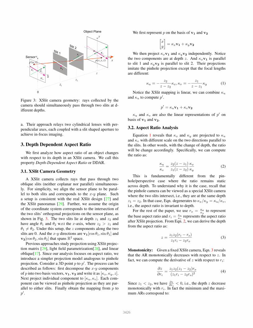
Figure 3: XSlit camera geometry: rays collected by the
camera should simultaneously pass through two slits at d-
ifferent depths.
a. Their approach relays two cylindrical lenses with per-
pendicular axes, each coupled with a slit shaped aperture to
achieve in-focus imaging.
3. Depth Dependent Aspect Ratio
We first analyze how aspect ratio of an object changes
with respect to its depth in an XSlit camera. We call this
property Depth-Dependent Aspect Ratio or DDAR.
3.1. XSlit Camera Geometry
A XSlit camera collects rays that pass through two
oblique slits (neither coplanar nor parallel) simultaneous-
ly. For simplicity, we align the sensor plane to be paral-
lel to both slits and corresponds to the x-y plane. Such
a setup is consistent with the real XSlit design [27] and
the XSlit panoramas [29]. Further, we assume the origin
of the coordinate system corresponds to the intersection of
the two slits’ orthogonal projections on the sensor plane, as
shown in Fig. 3. The two slits lie at depth z1 and z2 and
have angle θ1 and θ2 w.r.t the x-axis, where z2 > z1 and
θ1 6= θ2. Under this setup, the z components along the two
slits are 0. And the x-y directions are v1[cos θ1, sin θ1] and
v2[cos θ2, sin θ2] that spans R2 space.
Previous approaches study projection using XSlit projec-
tion matrix [29], light field parametrization[28], and linear
oblique[17]. Since our analysis focuses on aspect ratio, we
introduce a simpler projection model analogous to pinhole
projection. Consider a 3D point p to p′. The process can be
described as follows: first decompose the x-y components
of p into two basis vectors, v1, v2 and write it as [κx, κy, z].Next project individual component to [κu, κv]. Each com-
ponent can be viewed as pinhole projection as they are par-
allel to either slits. Finally obtain the mapping from p to
p′.
We first represent p on the basis of v1 and v2
[
xy
]
= κxv1 + κyv2
We then project κxv1 and κyv2 independently. Notice
the two components are at depth z. And κxv1 is parallel
to slit 1 and κyv2 is parallel to slit 2. Their projections
imitate the pinhole projection except that the focal lengths
are different:
κu = −z2
z − z2κx, κv = −
z1z − z1
κy (1)
Notice the XSlit mapping is linear, we can combine κu
and κu to compute p′.
p′ = κuv1 + κvv2
κu and κv are also the linear representations of p′ on
basis of v1 and v2.
3.2. Aspect Ratio Analysis
Equation 1 reveals that κx and κy are projected to κu
and κv with different scale on the two directions parallel to
the slits. In other words, with the change of depth, the ratio
will be change accordingly. Specifically, we can compute
the ratio as:
κu
κv
=z2(z − z1)
z1(z − z2)
κx
κy
(2)
This is fundamentally different from the pin-
hole/perspective case where the ratio remains static
across depth. To understand why it is the case, recall that
the pinhole camera can be viewed as a special XSlit camera
where the two slits intersect, i.e., they are at the same depth
z1 = z2. In that case, Eqn. degenerates to κx/κy = κu/κv ,
i.e., the aspect ratio is invariant to depth.
For the rest of the paper, we use ro = κx
κyto represent
the base aspect ratio and ri =κu
κvrepresents the aspect ratio
after XSlit projection. From Eqn. 2, we can derive the depth
from the aspect ratio as:
z =z1z2(ri − ro)
z1ri − z2ro(3)
Monotonicity: Given a fixed XSlit camera, Eqn. 3 reveals
that the AR monotonically decreases with respect to z. In
fact, we can compute the derivative of z with respect to ri:
∂z
∂ri=
z1z2(z1 − z2)ro(z1ri − z2ro)2
(4)
Since z1 < z2, we have ∂z∂ri
< 0, i.e., the depth z decrease
monotonically with ri. In fact the minimum and the maxi-
mum ARs correspond to:
3426
rmini = ri|z→∞ =
z2z1
ro, rmaxi = ri|z→z2 = ∞ (5)
Depth Sensitivity: Another important property we ad-
dress here is depth sensitivity. We compute the partial
derivative of ri respect to z for z ranging from z2 to ∞and we have:
∂ri∂z
=z2(z1 − z2)
z1(z − z2)2ro (6)
The sensitivity is the absolute value of ∂ri∂z
and it de-
crease monotonically for z > z2. This implies that as ob-
jects get further away, the depth accuracy recoverable from
the AR also decreases. According to Eqn. 6, the sensitivity
is positively related to z2z1
and z1−z2. Farther separated slit-
s and greater ratio between two slits distances corresponds
to higher sensitivity. This phenomenon resembles classical
stereo matching using two perspective cameras where the
deeper the object, the smaller the disparity and the less ac-
curacy that stereo matching can produce.
Depth Range: We can further compute the maximum dis-
cernable depth zmax. To do so, we first compute ri when
z → ∞ as r∞i = z2z1ro. Next we change r∞i with ǫ, the
smallest ratio change that is discernable in image. We have
r∗i = z2z1ro + ǫ. The lower bound of ǫ is 1/L, L is the
image width or height, without considering subpixel accu-
racy. Sine the depth changes monotonically with ri, the
maximum discernable depth is correspond to r∗i . Finally
we compute the depth use Eqn. 3:
zmax =z2z1
[z1 + (z2 − z1)roǫ] (7)
Eqn. 7 indicates that the larger slit distance ratio z2z1
and
bigger separating distance of two slits z2−z1 correspond to
a larger discernable depth range.
4. Depth Inference from DDAR
Our analysis reveals that if we know ro in prior, i.e., the
base aspect of the object, we can directly infer the object’s
depth from its aspect ratio in the XSlit camera. A typical
example is using an Parallel-Orthogonal XSlit camera (PO-
XSlit) to capture an up-right rectangle. In a PO-XSlit cam-
era, the slits are orthogonal and axis aligned. In this case, rodirectly corresponds to the aspect ratio of the rectangle and
ri corresponds to the observed AR of the project rectangle.
The simplest case is to capture a up-right square whose
aspect ratio ro = 1. From the AR change, we can directly
infer its depth using Eqn. 3. In practice, we do not know the
AR of the object in prior. However, many natural scenes
92.4 cm111.4 cm 61.5 cm
5.56
yκ=
8.74
xκ
=
Depth
Undistorted
1.32u
κ =
0.96
vκ
=
0.81u
κ =
0.62
vκ
=
0.66u
κ =
0.52
vκ
=
Cards with Shape Prior
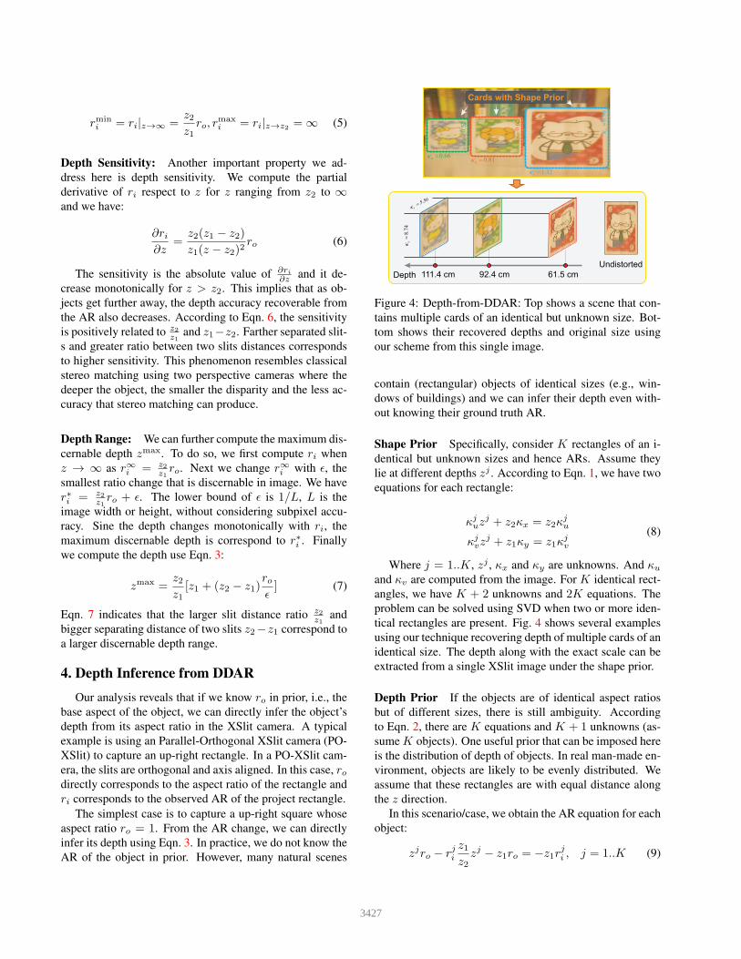
Figure 4: Depth-from-DDAR: Top shows a scene that con-
tains multiple cards of an identical but unknown size. Bot-
tom shows their recovered depths and original size using
our scheme from this single image.
contain (rectangular) objects of identical sizes (e.g., win-
dows of buildings) and we can infer their depth even with-
out knowing their ground truth AR.
Shape Prior Specifically, consider K rectangles of an i-
dentical but unknown sizes and hence ARs. Assume they
lie at different depths zj . According to Eqn. 1, we have two
equations for each rectangle:
κjuz
j + z2κx = z2κju
κjvz
j + z1κy = z1κjv
(8)
Where j = 1..K, zj , κx and κy are unknowns. And κu
and κv are computed from the image. For K identical rect-
angles, we have K + 2 unknowns and 2K equations. The
problem can be solved using SVD when two or more iden-
tical rectangles are present. Fig. 4 shows several examples
using our technique recovering depth of multiple cards of an
identical size. The depth along with the exact scale can be
extracted from a single XSlit image under the shape prior.
Depth Prior If the objects are of identical aspect ratios
but of different sizes, there is still ambiguity. According
to Eqn. 2, there are K equations and K + 1 unknowns (as-
sume K objects). One useful prior that can be imposed here
is the distribution of depth of objects. In real man-made en-
vironment, objects are likely to be evenly distributed. We
assume that these rectangles are with equal distance along
the z direction.
In this scenario/case, we obtain the AR equation for each
object:
zjro − rjiz1z2
zj − z1ro = −z1rji , j = 1..K (9)
3427
1
23
45
d0 +5 +15 +20 +251.05
1.15
1.25
1.4
Slope-Depth Curve
Depth
(cm)
Slope
1
2
34 5
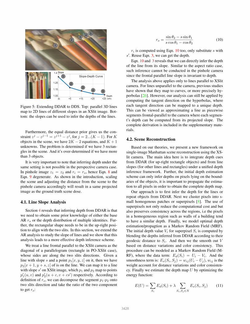
Figure 5: Extending DDAR to DDS. Top: parallel 3D lines
map to 2D lines of different slopes in an XSlit image. Bot-
tom: the slopes can be used to infer the depths of the lines.
Furthermore, the equal distance prior gives us the con-
straint zj − zj−1 = zj+1 − zj , for j = 2...(K − 1). For Kobjects in the scene, we have 2K − 2 equations, and K + 1unknowns. The problem is determined if we have 3 rectan-
gles in the scene. And it’s over-determined if we have more
than 3 objects.
It is very important to note that inferring depth under the
same setting is not possible in the perspective camera case.
In pinhole image z1 = z2 and ri = ro, hence Eqn. 8 and
Eqn. 9 degenerate. As shown in the introduction, scaling
the scene and adjusting the distance from the scene to the
pinhole camera accordingly will result in a same projected
image as the ground truth scene dose.
4.1. Line Slope Analysis
Section 4 reveals that inferring depth from DDAR is that
we need to obtain some prior knowledge of either the base
AR ro or the depth distribution of multiple identities. Fur-
ther, the rectangular shape needs to be in the up-right posi-
tion to align with the two slits. In this section, we extend the
AR analysis to study the slope of lines and we show that this
analysis leads to a more effective depth inference scheme.
We treat a line frontal parallel to the XSlit camera as the
diagonal of a parallelogram (rectangle in PO-XSlit case),
whose sides are along the two slits directions. Given a
line with slope s and a point p1[x, y, z] on it, then we have
p2[x+ 1, y + s, z] of is on the line. We can map it to a line
with slope s′ on XSlit image, which p1 and p2 map to points
p′1(u, v) and p′2(u + c, v + cs′) respectively. According to
definition of ro, we can decompose the segment p1-p2 onto
two slits direction and take the ratio of the two component
to get ro:
ro =sin θ2 − s sin θ1s cos θ1 − cos θ2
(10)
ri is computed using Eqn. 10 too, only substitute s with
s′. Reuse Eqn. 3, we can get the depth.
Eqn. 10 and 3 reveals that we can directly infer the depth
of the line from its slope. Similar to the aspect ratio case,
such inference cannot be conducted in the pinhole camera
since the frontal parallel line slope is invariant to depth.
The analysis above applies only to lines parallel to XSlit
camera. For lines unparallel to the camera, previous studies
have shown that they map to curves, or more precisely hy-
perbolas [26]. However, our analysis can still be applied by
computing the tangent direction on the hyperbolas, where
each tangent direction can be mapped to a unique depth.
This can be viewed as approximating a line as piecewise
segments frontal-parallel to the camera where each segmen-
t’s depth can be computed from its projected slope. The
complete derivation is included in the supplementary mate-
rials.
4.2. Scene Reconstruction
Based on our theories, we present a new framework on
single-image Manhattan scene reconstruction using the XS-
lit camera. The main idea here is to integrate depth cues
from DDAR (for up-right rectangle objects) and from line
slopes (for other lines and rectangles) under a unified depth
inference framework. Further, the initial depth estimation
scheme can only infer depths on pixels lying on the bound-
aries of the objects, it is important to propagate the estima-
tion to all pixels in order to obtain the complete depth map.
Our approach is to first infer the depth for the lines or
repeat objects from DDAR. Next we cluster pixels into s-
mall homogenous patches or superpixels [8]. The use of
superpixels not only reduce the computational cost and but
also preserves consistency across the regions, i.e the pixels
in a homogeneous region such as walls of a building tend
to have a similar depth. Finally, we model optimal depth
estimation/propagtion as a Markov Random Field (MRF).
The initial depth value Vi for superpixel Si is computed by
blending the depths inferred from DDAR according to their
geodesic distance to Si. And then we the smooth out Vbased on distance variations and color consistency. This
procedure can be modeled as a Markov Random Field (M-
RF), where the data term: Ed(Si) = Ui − Vi. And the
smoothness term is: Es(Si, Sj) = wij(Ui −Uj), wij is the
weight account for distance variations and color consisten-
cy. Finally we estimate the depth map U by optimizing the
energy function:
E(U) =∑
Si
Ed(Si) + λ∑
Si,Sj∈N
Es(Si, Sj) (11)
3428
Figure 6: An XSlit image of the arch scene that contains 3D
concentric circles (left). Their images correspond to ellipses
of different aspect ratios (right).
N represents the superpixel neighborhood. The problem
can be solved using the graph-cut algorithm [2].
5. Experiments
We experiment our approach on both synthetic and real
scenes. For synthetic scenes, we render images using 3ds
Max. For real scenes, we acquire images using the XSlit
lens as well as synthesize XSlit panoramas from video se-
quences.
Synthetic Results. We first render an XSlit images of a
scene containing repeated shapes (Fig. 6). The architecture
consists of concentric arches of depths ranging from 900cm
to 2300cm. We assume that the actual aspect ratio of the
arches is 1, i.e., a circle. We position a PO-XSlit camer-
a with z1 = −3.2cm and z2 = −346.7cm frontal paral-
lel to the arches and the images of the arches are ellipses
of different aspect ratios. Notice that in the pinhole case,
they will be map to circles. We first detect ellipses using
Hough transform and then measure their aspect ratios using
the major and minor axes. Finally, we use the ratios to re-
cover their depths using Eqn. 3. Our recovered depths for
the near and far arches are 906.6cm and 2281.0cm, i.e., the
errors are less than 2%.
Next we render two XSlit panoramas, one for the cor-
ridor and the second for the facade. Both scenes exhibit
strong linear structures with many horizontal and vertical
lines. Our analysis shows that for lines to exhibit DDS,
they should not align with either slit. Therefore, we rotate
the POXSlit, i.e., θ1 = 45◦ and θ2 = 135◦. For the corri-
dor scene, the XSlit camera has a setting of z1 = −3.6cm,
z2 = −717.9cm and for the facade scene, z1 = −3.1cm,
z2 = 4895.9cm. We first use the LSD scheme[24] to ex-
tract 2D lines from the XSlit images and cluster them in-
to groups of horizontal and vertical (in 3D) lines. This is
done by thresholding their aspect ratios Eqn. 5. For lines
in each group, we compute their depths using Eqn. 10 and
3. This results in a sparse depth map. To recover the full
XSlit Image
Stitching
Slit 2
Slit 1
Cylindrical lenses
Slit Aperture
Figure 8: XSlit images can be captured by a real XSlit lens
(left) or by stitching linearly varying columns from a 3D
light field (right).
depth map, we apply the MRF (Sec. 4.2) and the final result
is shown in Fig. 7. Our technique is able to recover dif-
ferent depth layers while preserving linear structures. For
comparison, we render a single perspective image and ap-
ply the learning-based scheme Make3D [20]. Make3D can
detect several coarse layers but cannot detect fine details as
ours since these linear structures appear identical in slope in
a perspective image but exhibit different slopes in an XSlit
image.
Real Results. We explore several approaches to acquire
XSlit images of a real scene: by a real XSlit lens and
through panorama synthesis. For the former, we use an
XSlit lens [26]. The design resembles the original anamor-
phoser proposed by Ducos du Hauron that replaces the pin-
hole in the camera with a pair of narrow, perpendicularly
crossed slits. Similar to the way of using a spherical thin
lens to increase light throughput in a pinhole camera, the
XSlit lens relay perpendicular cylindrical lenses, one for
each slit. In our experiments, we use two cylindrical lenses
with focal lengths 2.5cm (closer to the sensor) and 7.5cm
(farther away from the sensor) respectively. The distance
between the two slits is adjustable between 5cm and 12cm
and the slit apertures have a width of 1mm.
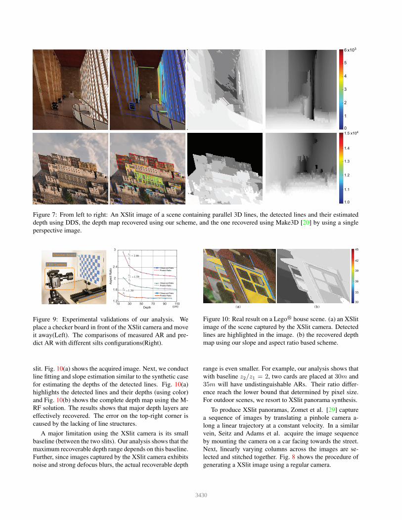
We first capture a checkerboard at known depths and
compare the measured AR and our predicted AR using E-
qn. 3. We test three different slit configurations, z2/z1 =1.3, z2/z1 = 1.59 and z2/z1 = 2.0. Fig. 9 shows that
the predicted AR curve fits well with the ground truth. In
particular, as an object gets farther away from the sensor,
its AR also changes slower. Further, the larger the base-
line z2/z1 is, the larger the aspect ratio variations across the
same depth range, as predicted by our theory.
Next, we verify our DDS analysis using images cap-
tured by the XSlit camera. In Fig. 10, we position a Legor
house model in front of the XSlit camera (z1 = 6.12cm and
z2 = 11.81cm). We rotate the XSlit camera by 45 degrees
so that the 3D lines on the house will not align with either
3429
63
x10
3
4
5
2
1
0
1.54
x10
1.1
1.0
1.3
1.4
1.2
Figure 7: From left to right: An XSlit image of a scene containing parallel 3D lines, the detected lines and their estimated
depth using DDS, the depth map recovered using our scheme, and the one recovered using Make3D [20] by using a single
perspective image.
XSlit Camera
10 30 50 70 90 1101.2
1.6
2
2.4
3
2
1
2.00z
z
=
2
1
1.59z
z
=
2
1
1.30z
z
=
Observed Ratio
Predict Ratio
Observed Ratio
Predict Ratio
Observed Ratio
Predict Ratio
Depth
Asp
ect R
atio
(cm)
Translation Track
Checker Board
Figure 9: Experimental validations of our analysis. We
place a checker board in front of the XSlit camera and move
it away(Left). The comparisons of measured AR and pre-
dict AR with different silts configurations(Right).
slit. Fig. 10(a) shows the acquired image. Next, we conduct
line fitting and slope estimation similar to the synthetic case
for estimating the depths of the detected lines. Fig. 10(a)
highlights the detected lines and their depths (using color)
and Fig. 10(b) shows the complete depth map using the M-
RF solution. The results shows that major depth layers are
effectively recovered. The error on the top-right corner is
caused by the lacking of line structures.
A major limitation using the XSlit camera is its small
baseline (between the two slits). Our analysis shows that the
maximum recoverable depth range depends on this baseline.
Further, since images captured by the XSlit camera exhibits
noise and strong defocus blurs, the actual recoverable depth
45
33
30
39
42
36
(a) (b)
Figure 10: Real result on a Legor house scene. (a) an XSlit
image of the scene captured by the XSlit camera. Detected
lines are highlighted in the image. (b) the recovered depth
map using our slope and aspect ratio based scheme.
range is even smaller. For example, our analysis shows that
with baseline z2/z1 = 2, two cards are placed at 30m and
35m will have undistinguishable ARs. Their ratio differ-
ence reach the lower bound that determined by pixel size.
For outdoor scenes, we resort to XSlit panorama synthesis.
To produce XSlit panoramas, Zomet et al. [29] capture
a sequence of images by translating a pinhole camera a-
long a linear trajectory at a constant velocity. In a similar
vein, Seitz and Adams et al. acquire the image sequence
by mounting the camera on a car facing towards the street.
Next, linearly varying columns across the images are se-
lected and stitched together. Fig. 8 shows the procedure of
generating a XSlit image using a regular camera.
3430
(a) Scene Setup (b) Captured Image
Pinhole Camera
Cylindrical Mirror
Cube
A
BC
AR = 0.88
AR = 0.52
AR = 0.67
A
B
C
Figure 12: Results on catadioptric mirrors. Left: we capture the scene using a cylindrical catadioptric mirror. Right: the
aspect ratios of cubes change with respect to their depthes.
Figure 11: The XSlit image of an outdoor scene. Left: An
XSlit panorama and the detected lines. Right: The recov-
ered depth map.
Fig. 11 shows the XSlit panorama synthesized from an
image sequence captured by a moving camera. We linearly
increase the column index in terms of frame number and
stitch these columns to form an XSlit image. The moving
path of the camera is 55cm long. And the camera is tilt with
20◦ angle. The resulting two slits are at -1.8cm and 41cm
respectively.
Recent ray geometry studies [7] show that reflections of
certain types of catadioptric mirror can be approximated as
an XSlit image. In Fig. 12, we position a perspective camer-
a facing towards a cylindrical mirror and Fig. 12(b) shows
that DDAR can both be observed on the acquired image.
In particular, we put multiple cubes of an identical size at
different depths and their aspect ratios change dramatical-
ly. This is because two virtual slits of the catadioptric mir-
ror are separated far away where DDAR is more significant
than the XSlit camera case.
6. Conclusion and Further Work
We have comprehensively studied the aspect ratio (AR)
distortion in XSlit cameras and exploited its unique depth-
dependent property for 3D inference. Our studies have
shown that unlike perspective camera that preserves AR un-
der depth variations, AR changes monotonically with re-
spect to depth in an XSlit camera. This has led to new depth-
from-AR schemes using a single XSlit image. We have fur-
ther shown that similar to AR variations, the slope of pro-
jected 3D lines will also vary with respect to depth, and
we have developed theories to characterize such variations
based on AR analysis. Finally, AR and line slope analysis
can be integrated for 3D reconstruction and we have exper-
imented on real XSlit images captured by an XSlit camera,
synthesized from panorama stitching, and captured using a
catadioptric mirror to validate our framework. We admit
that the proposed depth-from-AR technique is not yet com-
parable to state-of-the-art multi-images (stereo or SfM) or
active illumination (Kinect) based techniques. However, a
simpler setup lends itself to more cost-effective depth sens-
ing systems. We also hope our work would stimulate more
work in the less explored space of single XSlit imaging.
There are a number of future directions we plan to ex-
plore. Our cylindrical lens based XSlit has a small baseline
(i.e., the distance between the two slits) and therefore can
only acquire AR changes within a short range. Construct-
ing a large baseline XSlit camera will be costly as it is dif-
ficult to fabricate large form cylindrical lens. A more feasi-
ble solution would be adopt a cylindrical catadioptric mirror
where the reflection image can be approximated as an XSlit
image. In the future, we will explore effective schemes for
correcting both geometric distortion and blurs due to imper-
fect mirror geometry. We will also investigate integrating
our AR based solution into prior based frameworks to en-
hance reconstruction quality. For example, a hybrid XSlit-
perspective camera pair can be constructed. Finally, since
AR distortions commonly exhibit in synthesized panoramas
as shown in the paper, we plan to study effective image-
based distortion correction techniques to produce perspec-
tively sound panoramas analogous to [1].
3431
Acknowledgements
This project was supported by the National Science
Foundation under grants IIS-1513031 and IIS-1422477.
References
[1] A. Agarwala, M. Agrawala, M. F. Cohen, D. Salesin, and
R. Szeliski. Photographing long scenes with multi-viewpoint