R E P O R T T RESUMES ED 021 110 VT 005 693 AUTOMOTIVE DIESEL MAINTENANCE 2. UNIT IX, AUTOMATIC TRANSMISSIONS -- HYDRAULIC SYSTEM (PART I). HUMAN ENGINEERING INSTITUTE, CLEVELAND, OHIO REPORT NUMBER AM-2-9 PUB DATE 2 JUN 67 EDRS PRICE MF-$0.25 HC-$1.56 37P. DESCRIPTORS- *STUDY GUIDES, *TEACHING:GUIDES; *TRADE AND INDUSTRIAL EDUCATION, *AUTO MECHANICS (OCCUPATION), *HYDRAULICS,. DIESEL ENGINES, MOTOR VEHICLES, KINETICS, EQUIPMENT MAINTENANCE, ADULT VOCATIONAL EDUCATION, TRANSPARENCIES, PROGRAMED MATERIALS, INDIVIDUAL INSTRUCTION, INSTRUCTIONAL FILMS, PROGRAMED INSTRUCTION, THIS MODULE OF A 25-MODULE COURSE IS DESIGNED TO DEVELOP AN UNDERSTANDING OF THE OIL FLOW WITHIN HYDRAULIC TRANSMISSIONS USED ON DIESEL POWERED VEHICLES. TOPICS ARE GENERAL DESCRIPTION, HYDRAULIC CIRCUITS, AND BRAKE HYDRAULIC CIRCUIT AND OPERATION. THE MODULE CONSISTS OF A SELF-INSTRUCTIONAL PROGRAMED TRAINING FILM "LEARNING ABOUT THE ALLISON TORQMATIC HYDRAULIC SYSTEM (PART II)" AND OTHER MATERIALS. SEE VT 005 685 FOR FURTHER INFORMATION. MODULES IN THIS SERIES ARE AVAILABLE AS VT 005 685 VT 005 709. MODULES FOR "AUTOMOTIVE DIESEL MAINTENANCE 1" ARE AVAILABLE AS VT 005 655 - VT 005 684. THE 2-YEAR PROGRAM OUTLINE FOR "AUTOMOTIVE DIESEL MAINTENANCE 1 AND 2" IS AVAILABLE AS VT 006 006. THE TEXT MATERIAL, TRANSPARENCIES, PROGRAMED TRAINING FILM, AND THE ELECTRONIC TUTOR MAY BE RENTED (FOR $1.75 PER WEEK) OR PURCHASED FROM THE HUMAN ENGINEERING INSTITUTE, HEADQUARTERS `AND DEVELOPMENT CENTER, 2341 CARNEGIE AVENUE, CLEVELAND, OHIO 44115. (HC) ) , J
Transcript
R E P O R T T RESUMESED 021 110 VT 005 693AUTOMOTIVE DIESEL MAINTENANCE 2. UNIT IX, AUTOMATICTRANSMISSIONS -- HYDRAULIC SYSTEM (PART I).HUMAN ENGINEERING INSTITUTE, CLEVELAND, OHIOREPORT NUMBER AM-2-9 PUB DATE 2 JUN 67EDRS PRICE MF-$0.25 HC-$1.56 37P.
THIS MODULE OF A 25-MODULE COURSE IS DESIGNED TO DEVELOPAN UNDERSTANDING OF THE OIL FLOW WITHIN HYDRAULICTRANSMISSIONS USED ON DIESEL POWERED VEHICLES. TOPICS AREGENERAL DESCRIPTION, HYDRAULIC CIRCUITS, AND BRAKE HYDRAULICCIRCUIT AND OPERATION. THE MODULE CONSISTS OF ASELF-INSTRUCTIONAL PROGRAMED TRAINING FILM "LEARNING ABOUTTHE ALLISON TORQMATIC HYDRAULIC SYSTEM (PART II)" AND OTHERMATERIALS. SEE VT 005 685 FOR FURTHER INFORMATION. MODULES INTHIS SERIES ARE AVAILABLE AS VT 005 685 VT 005 709. MODULESFOR "AUTOMOTIVE DIESEL MAINTENANCE 1" ARE AVAILABLE AS VT 005655 - VT 005 684. THE 2-YEAR PROGRAM OUTLINE FOR "AUTOMOTIVEDIESEL MAINTENANCE 1 AND 2" IS AVAILABLE AS VT 006 006. THETEXT MATERIAL, TRANSPARENCIES, PROGRAMED TRAINING FILM, ANDTHE ELECTRONIC TUTOR MAY BE RENTED (FOR $1.75 PER WEEK) ORPURCHASED FROM THE HUMAN ENGINEERING INSTITUTE, HEADQUARTERS`AND DEVELOPMENT CENTER, 2341 CARNEGIE AVENUE, CLEVELAND, OHIO44115. (HC)
),J
STUDY AND READING MATERIALS
AUTOMOTIVE
azg,.t1MAINTENANCE
AUTOMATIC TRANSMISSIONS -HYDRAULIC SYSTEM PART I;
UNIT IX
SECTION A GENERAL DESCRIPTION
SECTION B HYDRAULIC CIRCUITS
SECTION C BRAKE HYDRAULIC CIRCUITAND OPERATION
AM 2-96/2/67
U.S. DEPARTMENT OF HEALTH, EDUCATION & WELFARE
OFFICE OF EDUCATION
THIS DOCUMENT HAS BEEN REPRODUCED EXACTLY AS RECEIVED FROM iris
PERSON OR ORGANIZATION ORIGINATING IT. POINTS OF VIEW OR OPINIONS
STATED DO NOT NECESSARILY REPRESENT OFFICIAL OFFICE OF EDUCATION
POSITION OR POLICY.
HUMAN ENGINEERING INSTITUTE
AM 2-9
This unit describes in detail the oil flow through the CLBT 5960 AllisonTransmission. Each component which plays a role in this system will bediscussed.
SECTION A -- GENERAL DESCRIPTION
The transmission hydraulic system is primarily self-contained. Theexternal lines are: the oil cooler inlet and outlet lines, main oil pressuretransfer tube, lube oil lines and the scavenge pump discharge tube.
Major components of the system are: input driven charging and scavengepump; the main regulator valve; range control valve assembly, containingthe intermediate trimmer and neutral trimmer valves; the brake (retarder)control valve, containing the torque limiter valve; and the lock-up body,containing the flow and lock-up shift valves.
The input driven pressure pump is mounted on the converter housing andis driven by the converter accessory drive gear train. The gear trainconsists of a drive gear attached to the converter pump, idler gear andaccessory driven gear. The pump is driven at engine speed and has acapacity of 54 gpm at 2100 engine rpm. Pressurized oil is supplied by thepump to the transmission clutches, transmission lube and converter.
SECTION B -- HYDRAULIC CIRCUITS
NOTE: Refer to Figure 1 (Allison color foldout sheet), unless otherwisespecified, during the following discussion.
MAIN REGULATOR VALVE -- The main regulator valve regulates the oilpressure for the transmission clutches and directs the overage to theconverter.
AM 2-9
The input driven charging pump brings oil from the transmission sump anddirects it to the main pressure regulator valve. The check valve, whichis found on the converter housing face, prevents a reverse flow of oil, whenthe unit is traveling in a reverse direction.
Under normal operation, the oil will flow into the main regulator valve andthrough the filters. If the filter elements are clogged, or the oil is ex-ceptionally heavy, the oil will open the bypass valve and dump unfilteredoil into the main regulator valve.
The main regulator valve contains a dash-pot valve, which consists of asmall ball and spring. As the oil flows through the regulator valve, thedash-pot valve is unseated, allowing oil to flow behind the regulator valve.This oil acts as a cushion and absorbs shock as the regulator valve fluttersback and forth. As oil flows through the valve and into the main oil line,the oil acts against the regulator spring. Thi.s compresses the spring andshifts the valve over, allowing excess main oil to flow into the converterIN line; see Figure 2. When the pressure is dissipated, spring pressuremoves the regulator valve back to its original position, shutting off theconverter IN oil.
BOOSTER SIGNAL PLUG MAIN REGULATOR VALVE.,
CONVERTER IN OILEXHAUST OIL FROM FILTERS
BOOSTER SIGNAL PITOT PRESSURE
lig. 2 Main pressure regulator valve in dump position
- 2 -
AM 2-9
Two other hydraulic circuits (pitot and booster signal) have governingeffects on the main regulator valve.
Pitot oil pressure is fed through a small orifice in the converter IN line.This oil flows into the pitot can, which is pressed on the splitter low drum,As the can revolves, oil is thrown by centrifugal force against the OD ofthe can. The revolving oil is then thrown against the pitot tube, forcinga small amount of the oil into the tube. Oil flows through the pitot feedline and into the main regulator valve, around the anti-spring end of thelock-up shift valve and is dead-ended in the lock-up shift valve; seeFigure 1.
At the main regulator valve, pitot pressure is exerted on the valve, which,slightly compresses the regulator spring, thus requiring less mainpressure to shift the valve into its dumping position; see Figure 2.
Pitot pressure is proportional to turbine shaft speed. Therefore, at higherturbine shaft speeds. more pitot pressure is exerted on the regulator valve,decreasing the amount of main pressure to the clutches as requirementsare lessened due to increasing speed and decreasing torque. The pitotpressure ranges from 0 - 90 psi.
Pitot pressure is also exerted on the . 75 psi differential check valve,located in the pitot-main oil passage. Pitot pressure can rise and mainpressure can fall until pitot pressure exceeds the main pressure by 0. 75psi. At this point, pitot pressure will escape into the main pressurecircuit at the check valve, and afterward will, for all practical purposes,remain balanced. The possibility of pitot pressure exceeding mainpressure is very remote. This can occur, in some instances, where theengine over-speeds and drives the turbine shaft at exceedingly high speeds.
Booster signal pressure is the other factor which affects main oil pressure.This pressure influences main oil pressure in first and reverse gearranges only.
- 3 -I
AM 2-9
When the control valve is in one of the previously mentioned positions, thebooster signal feed line is opened, permitting oil to flow into the springend of the regulator valve. Oil pressure is exerted on the booster plug,which compresses the spring and forces the regulator valve to regulate athigher pressures. Figure 3 illustrates the effects that pitot and boostersignal pressure have on main pressure in different gear ranges.
230220
200
180
160a:
I40
120cr)cr)
ccw 100a,
80
60
40
20
0
MAIN PRESSURE IN 1ST, R
MAIN PRESSURE INN, 2ND, 3RD, 4TH, 5TH, 6TH
1
PITOT PRESSURE
400 800 1200 1600 2000 2400TURBINE SPEED IN R.PM
MAIN AND PITOT PRESSURE
Fig. 3 Pressure curves
Regulated main oil flows into the control valve body. Oil flow through thevalve body is dependent on control valve position. This will be coveredlater in this unit.
CONVERTER SYSTEM -- The converter IN oil is the overage main oil thatis dumped into converter IN line by the main pressure regulator valve. Oil
4
AM 2-9
flows into the converter through the ground sleeve and pump hub bearing
and into the cavity between the pump and stator. It continues to flow
through the converter elements and out between the ground sleeve and
turbine shaft.
TI_:_. converter IN passage incorporates a safety blow-off valve which
prevents the converter IN pressure from exceeding 80 psi. Oil pressure
in excess of 80 psi is dumped back into transmission sump.
Between the converter IN and the converter OUT passage is the converter
bypass valve. During high speed operation, the converter does not require
the amount of oil being directed to it. Therefore, when converter IN
pressure exceeds converter OUT pressure by 3 psi the valve opens,
allowing excessive converter IN oil to bypass the torque converter.
Converter OUT oil flows through the oil cooler, where it is cooled. The
oil continues its flow to the secondary converter pressure regulator valve.
This valve works against a spring pressure and will exhaust to sump any
oil in excess of 22.5 psi coming from the converter through the cooler.
Located in the converter housing between the oil cooler return and the
converter ml pressure passage, is the converter IN check valve. This
valve will not allow converter IN pressure to drop lower than 20. 5 psi.
Oil pressure on the cooler side of the valve is regulated at 22. 5 psi by the
converter pressure regulator valve. Oil pressure on the opposite side of
the valve is opposed by converter IN pressure and a 2 psi valve spring.
If converter IN oil pressure should drop below 20. 5 psi, oil from the oil
cooler, regulated at 22. 5 psi by the converter regulator valve, opens the
valve and maintains a minimum converter IN pressure of 20.5 psi. Thus,
oil is allowed to recirculate to the converter from the cooler.
TRANSMISSION LUBE SYSTEM -- Transmission lube oil is taken from
the converter IN line through a drilled hole in the converter ground sleeve
and flows through the center of the turbine shaft, splitter shaft and trans-
- 5 -
........,
AM 2 -9
mission output shaft. The oil passage in the transmission output shaft isnot drilled completely through. Radially drilled oil passages in the shaftprovide lubi ication for the planetary gearing. Oil is thrown out by cen-trifugal force to lubricate the clutch plates and intermediate needle bearingsand planetary spindle. Positive feed is maintained to all other spindlesand bearings, and a pressure drop exists across all feed lines; seeFigure 1.
PITOT SYSTEM -- The pitot system has two functions in the transmissionhydraulic system: (1) to reduce main pressure at higher turbine shaftspeeds and (2) to shift the converter into lock-up.
FLOW VALVE -- The purpose of the flow valve is to carry the lock-upclutch pressure oil to the sump whenever a shift is made.
Main oil flows into the lock-up valve body and then flows around the flowvalve and also behind it. The oil then flows through an orifice and into themain oil passage leading to the other end of the flow valve and also to thecontrol valve. Oil passes through the small check valve orifice and slowlyfills the cavity behind the valve, thus retaining the valve in its normalposition. See Figure 4.
When a shift is made, the oil required to fill the clutch being applied, re.duces the pressure on the control valve side of the flow valve orifice.Simultaneously, the pressure on the check valve end of the flow valve isreduced and full line pressure on the opposite end of the valve will movethe valve against the plug. This allows line pressure to bypass the flowvalve orifice and flow directly to the piston housing of the clutch beingapplied, permitting the shift to be made with full main pressure andassuring quick clutch engagement. The lock-up clutch feed oil is blockedoff and lock-up clutch passage is open to sump. See Figure 5.
9
ORIFICE()CHECK VALVE
lyttmtin,- TO CONTROL VALVE
FLOW VALVE
I TO LOCK-UP CLUTCHEXH.
LOCK- UPSHIFT VALVE
FR M MAIN REGULATOR VALVE
fltOT
Fig. 4 Flow valve in closed position
MAIN OILPITOT OIL
AM 2-9
,
Once the clutch needs are satisfied, oil once again flows through the orificein the check valve and slowly fills the cavity behind the flow valve. Sincethis end of the valve has a greater area than the other end of the valve, theeffective force from the oil pressure will also be greater; the valve willbe shifted to its normal position when the effective force on the larger end
ORIFICE() CHECVALVE
FROM LOCK UP CLUTCH EXHAUSTEXH.
FROM MAIN REGULATOR VALVE
Fig. 5 Flow valve in opened position
- 7 -
EXHAUSTMAIN OILPITOT OIL
AM 2-9
of the valve overcomes the force on the smaller end. This once againprovides an orificed oil flow to the applied clutches.
The orifice in the valve body is designed to replace oil lost through normalpiston seal leakage.
LOCK-UP SHIFT VALVE -- The lock-up shift valve, which is located inthe lock-up valve body, is shifted hydraulically and is dependent on turbineshaft speed (pitot pressure). Lock-up occurs in all ranges.
Main oil flows into the valve body and around the center of the lock-upvalve. Pitot oil flows into the valve body, and around the right hand endof the valve. Spring pressure acts on the left hand end of the valve.
As turbine shaft rpm increases, pitot pressure also increases since it isproportional to turbine shaft rpm. When pitot pressure becomes highenough, it overcomes the spring pressure and moves the lock-up valveagainst the plug, allowing main oil pressure to flow into the lock-up clutchfeed line. See Figure 6. The oil pressure actuates the lock-up pistonwhich, in turn, locks the turbine to the engine flywheel.
When turbine shaft rpm drops sufficiently, spring pressure overcomespitot pressure and shifts the valve out of lock-up, breaking the connectionbetween main oil and lock-up feed lines. The lock-up feed line is nowconnected to sump allowing the lock-up to return to sump and release the
clutch. The shift out of lock-up occurs when the turbine shaft speed dropsto about 1570 rpm.
Shifting into another speed range also disengages the lock-up clutch becauselock-up feed oil is dumped into sump, as discussed previously in the flow
valve discussion.
I
a
Jo
Li,
Ei
Li
0:ORIFICE!) CHECKVALVE
MAIN OILPITO?' OIL
LOCKUP rap
..;:, 6. Lock-up shift- valve in opened position
SIX SPEED MANUAL CONTROL VALVE -- The control valve is an eightposition, spool type valve, mounted vertically on the right side of thetram-3411s Sionhouiirig. The vertical mounting prevents the valve fromhithng due to cab flexing. Contained within the valve housing is the
intermediate trimmer valve and neutral trimmer valve; see Figure,1.- Thefunction and operation of both valves will be brought out during discussion,of the. oil flow to the various speed ranges.
AM 2-9
NEUTRAL -- In this valve position, main oil flows into the low splitter feeds _line and to the neutral trimmer valve. Neutral signal pressure4lows to the-optiOsite end of the neutral trimmer valve assembly, moving the :trimmer , ,plug against the trimmer valve. This positions the tpimpler, valve., so thatit produces the trininder action desired when shifting from neutral, to/firstor reverse range. All other range feed lines are open to exhaust andreturn to Sump.
FIRST RANGE -- When the shift is made from neutral to first mget the,neutral signal passage of the neutral trimmer valve is opened to exhaust,allowing main oil pressure to move the trimmer valve to the right, opening
- 9 -
AM 2-9
the exhaust port momentarily. Main pressure passes thi ugh the orificein the trimmer valve, moving the trimmer plug against its stop. Oilpressure builds up beneath the trimmer valve until it is equal to mainpressure. Then, spring pressure will move the trimmer valve and closethe trimmer valve exhaust.
When the control valve is shifted to the first range position, main pressureis directed to the low splitter and low pistons. At the same time, oil flowsinto the booster signal feed line, which helps maintain main pressure at ahigher level.
SECOND RANGE -- In this valve position, the oil flow:: to the low clutchremains the same. The low splitter clutch passage is opened to exhaust,and main pressure is directed to the splitter high clutch, applying highsplitter piston. However, booster signal is opened to exhaust, thus re-quiring less main pressure to apply the high splitter clutch.
THIRD-AANGE: In the third range pOsitiOn; main presstire oil flow isditoctol:fo. the splitter id* ClUtCh, applying the low splitter- pistons and_tothe intermediate Chitch,- applying the intermediate piston. Simultaneously,the high sPlittet and loW clutches are exhausted. Before the interinediate,.pistoVi8;-applied, the Main pressure must pass through an orificed passageand:tO the intermediate trimmer valve.
P-t0:000' against the triintner valve moves the valve, allowing ma*pfe8iite-tid:DO,ttlaW exhaust to sump, and applying pressure to the inter-taedlijato*::tilat6ii; Oil is forced through the orifiCed opening in the trimmer
'Wherilthe combined pressure of the valve springs and the main oil,presSuke on. the Surfade Of the trimmer valve exceeds the oil pressureon the fat.0 of th6 'valve, the valve shirts to the right, closing the exhaustport and sending full main pressure to the intermediate piston. Thisaction prevents shock loading to intermediate clutches and .allows forsmddthet bhifting.
r
AM 2-9
FOURTH RANGE -- In this range, oil continues to flow to the intermediatepiston (intermediate clutch). The low splitter clutch is exhausted, and thehigh splitter clutch feed is opened by the control valve, allowing oil toenter the splitter high range piston housing.
FIFTH RANGE -- In this range, oil is directed to the high piston (highrange clutch) and to the low splitter piston (splitter low clutch), therebyapplying these clutches. Simultaneously, the high splitter and intermediateclutches are exhausted.
SIXTH RANGE -- In this range, oil continues to flow to the highpiston (high range clutch). The high splitter clutch feed is opened by thecontrol valve, allowing oil to enter the splitter high range piston housing,and the low splitter clutch is then exhausted.
REVERSE RANGE -- When the control valve is shifted to this position,the neutral signal passage of the neutral trimmer valve is opened to ex-haust, allowing main oil pressure to move the trimmer valve to the right,opening the exhaust port momentarily. Main pressure passes through theorifice in the trimmer valve, moving the trimmer plug against its stop.Oil pressure builds up beneath the trimmer valve until is is equal to mainpressure. Then, spring pressure will move the trimmer valve and closethe trimmer valve exhaust.
At the same time, main oil pressure is being directed to the splitter lowand reverse range pistons, applying these clutches. Main pressure alsois being directed to the signal feed line, which unseats the booster plugin the main regulator and increases the main pressure, thus applyinggreater pressure against the low splitter and reverse range pistons.
AM 2-9
SECTION C BRAKE HYDRAULIC CIRCUIT AND OPERATION
NOTE: This circuit is sometimes referred to as the "RETARDER" circuit.
OIL FLOW -- Converter OUT oil flows from the converter and into the
cooler circuit. Regardless of the brake valve poLition, excess converterOUT oil flows into the oil cooler.
With the brake valve OFF oil flows around the valve and through thesecondary converter pressure regulator valve and into exhaust. If the
brake valve is ON, oil will enter the brake cavity at 22.5 psi.
The secondary converter pressure regulator valve assures rapid fillingof the brake cavity and also guarantees that brake IN oil will enter the
brake at 22.5 psi.
With the brake valve in the ON position, oil from the cooler enters thebrake valve and flows simultaneously against the secondary converterregulator valve and into the brake, feed line. The secondary converter_
regulator valve regulates brake fill pressure at 22.5 psi. Oil with
pressure in excess of 22.5 psi will be dumped into exhaust.
Brake feed oil enters the brake cavity near the ID and the movement of
the brake rotor forces the oil out and into the brake OUT line. Brake
OTT oil acts on the 50 psi torque limiter valve, which regulates torqueabsorption at 12,00 foot pounds.
If the brake attempts to absorb torque in excess of 1200 foot pounds
(over 50 psi), the excess oil flows through the torque limiter valve andinto the brake sump. With the brake absorbing less than 1200 foot pounds
of torque (less than 50 psi), the oil flows into the oil cooler, where it is
cooled and then flows back into the brake feed line. This cycle is re-peated until the brake valve is returned to the OFF position.
fj
Cl
AM 2-9
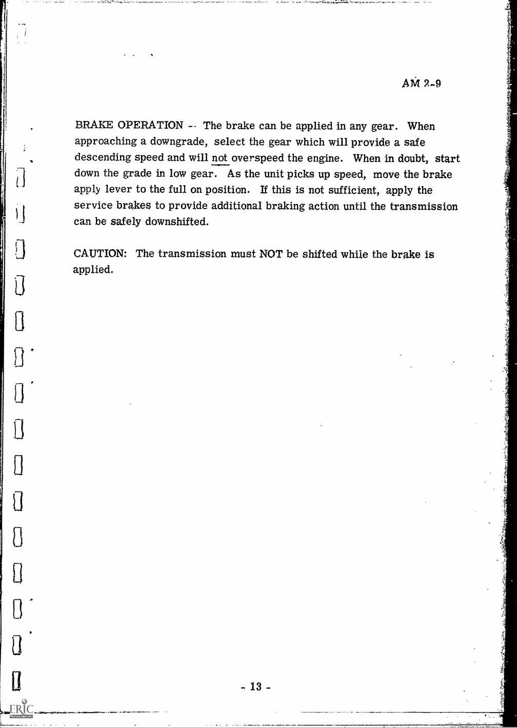
BRAKE OPERATION -- The brake can be applied in any gear. Whenapproaching a downgrade, select the gear which will provide a safedescending speed and will not overspeed the engine. When in doubt, startdown the grade in low gear. As the unit picks up speed, move the brakeapply lever to the full on position. If this is not sufficient, apply theservice brakes to provide additional braking action until the transmissioncan be safely downshifted.
CAUTION: The transmission must NOT be shifted while the brake isapplied.
LEARNING ABOUT THE ALLISON TORQMATICTRANSMISSION HYDRAULIC SYSTEM
Human Engineering Minn. State Dept. of Ed.Institute Vocational Education
Press A V., Check to be sure that timer is OFF.
NEUTRAL RANGE HYDRAULIC ACTION-- (refer toFigure 1 in AM 2-9 as you read through the followingframeS7)
When the manual selector valve is shifted to neutralwhile the engine is idling, the hydraulic system re-sponds as follows: oil is drawn from the sump andforced into the hydraulic circuit. The oil flowsthrough the filters, then to the main pressure regulatorvalve. From the regulator valve, oil flows to the lock-up shift valve and to the flow valve.
NOTE: Read this again before going to the next frame.
Press A of1-3
11.
The pressure acting on the flow valve moves it in adirection which bypasses the orifice, allowing oil toflow unrestricted through the valve. When the valvemoves. any oil at the end of the valve apposite theorifice will be displaced by the valve movement, willunseat the check valve at that end and flow into themain circuit beyond the flow valve.
NOTE: Read this again before going to the next frame.
Press Aj 1-5
No. Oil first goes to the filters, then to the mainpressure regulator, then to the lock-up shift valve.Read the last few frames again and follow the flowcarefully on the figure in Unit AM 2-9.
Press A 3
1-7
r . .
AM 2-9DFILM no, 8/18167
This film unit continues with the discussion of theTorqmatic hydraulic system. All eight p:.e.itions ofthe transmission will be covered in relation to whatoccurs in the hydraulic system.
Read each frame carefully and tz.i-ze your ti:ne beforeanswering the questions.
NOTE. Figure 1 (fold-out' in AM 2-9 be referredto in this film -- have it avail:Tag as you review thislesson.
Press A 31-2
Main oil pressure to the lock-up shift valve is stoppedat the valve. When oil reaches the flow valve it mustflow through an orifice. The oil then flows through aftorifice in a check valve to the opposite end of the flowvalve. 011 also is directed to the manual selectorvalve. When oil is required beyond the flow valve, theoil pressure decreases at the end of the flow valveopposite incoming main pressure.
NOTE: Read this again before going to the next frame.
Press A 1-4
Looking at Figure 1 in AM 2-9, with the engine idlingand the shift lever in neutral, oil flows first to the
(1) , then to the (2) , and onto the (3) where it is stopped.
shift valve 1C. Neither of the sequences in A or B is correct g
1-5
Correct. Oil first flows from the sump to the filters,then to the main pressure regulator valve, then to thelock-up shift valve.
When oil reaches the flow valve it flows
A.B.
C.
unrestricted through the valve fthrough two orifices 1/around the valve to the selector valve /10
1-13
QIIACTOR PAGE no, .
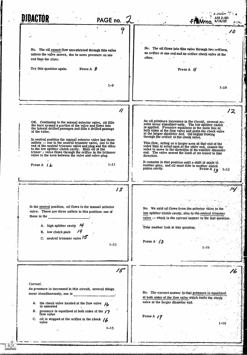
No. The oil cannot flow unrestricted through this valveunless the valve moves, due to more pressure on oneend than the other.
Try this question again. Press A
1 -9
/1
OK. Continuing to the manual selector valve, oil fillsthe bore around a portion of the valve_and flows intothe lateral-drilled passages and fills a drilled passageof the valve.
In neutral position the manual selector valve haS threeoutlets -- one to the neutialtrinnifer valve; one to the-end of the neutral trimmer -valve and plug.and the otherto the low splitter clutch cavity. Main oil at thetrimmer : valve flows through the orifice in the-trinimervalve to the area between the valve and valve plug.
Press A j 2_
In the neutral position, oil flows to the manual selectorvalve. There are-three outlets in this position; one ofthese is the
A. high splitter cavity
B. low clutch pack ptC. neutral trimmer valve 161.
1-13
Correct.As pressure is increased in this circuit, several thingsoccur simultaneously; one is
A. the check valve located at the flow valve 4,is unseated . '.
B. pressure is equalized at both sides of the /7flow valve
C. oil is stopped at the orifice in-the check /4valve
1-15
1
- AM 24Dmfna..8./18/07.
No. The oil flows into this valve through two orifices,an orifice at one-end-and 'an:Orifice check valve at theother.
Press A 1/
140
/0
As oil pressure increases-in thedirchit, -severalsnits occur simultaneously. "Theldw-splitter clutch --is applied. Pressure equalizes in-the main line atboth sides ,of the flow valve and-seats_the check vabieat the larger _did** end: -9ll'isgilis.flOwingthroUgh.the orifite inthe-, Cheek
acting on a:larger-area atthat-end-of=thevalve than is adted.Uponnt-Alie Other-end, catiseslhevalVe to moire in the direction Of- itssnialler diameterend. The valve moves the linlitolits traVeLin thatdirection. -It remains in that position-until a-Shift is made toanother gear, and oil must-flow to another clutchpiston cavity. Press
No. We.saiti-oilfiows,frOm the selector Valyeto_thelow splitter=clutch.cavity;.also.-to-thetnentrai.trininiervalve -- which is.the correct -allow to:the :last question:
,
Take another look at this question:.
Press A' /,3
No. The correctanSw.er islhatpressure-,is equalized:at both sides- of-the_flow valve which-seats the die* ,
valve at the larger diarnefer end.
Press A IT1 =16:
Pi - PAGE no.
. /7.0K. As the pressure is equalized at both sides of thenow valve, the check valve is seated. This actioncauses the valve to move to the smaller diameter mid,where it stays until a shift is made.
This action of the flow valve occurs every time thereis a sufficient flow of oil through it. However, the flowvalve has no purpose other than to disengage the lock-up clutch when a shift is made. At such times, themovement of the flow valve opens ports which exhaustslock-up clutch apply pressure to sump,which shuts offits oil supply. Therefore, it is evident that the primarypurpose of the flow valve is to automatically place thetransmission in ca-eerter operation, during a rangeshift, either up or down.
Press A /8 1-17
- - AM 2-9DFILM no, 8/18/67
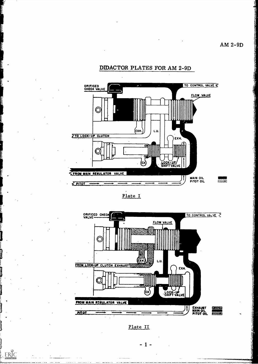
No. Look at Plate I again. The line marked L. U.shows no flow going through it. The lock-up shiftvalve is also closed. Try this question again.Press A f 9
..,MMMINI=.0
Correct. Main oil pressure has stabilized the flow valveby slowly filling the gap behind the valve. In this con-dition, the valve is in its normal position.
Look at Plate H. Which one of the following statementsapplies to this hydraulic schematic?
A. Full main pressure is being applied to oneof the clutch packs.
B. The lock-up clutch is engaged. 2,2.C. The transmission is in neutral. 2.3 1-21
No. Look at Plate II. Full main pressure is flowingpast the flow calve to the control valve This meansa. clutch pack is requiring pressure (in addition to oneof the splitter clutch packs). This diagram indicatesthat a shift has just been made.
Press A -4
RXIONflaWaiiiierrr
02,3
1-23
Look at Plate I. Which of the following statementsapplies to this hydraulic schematic?
A. Lock-up clutch pressure is being applied. /7
B. A shift has just been made. 2
C. The flow valve is hydraulically stable. 7-1
1-18
r--e%
/S>
fl
No. Remember, we said that if a shift has just beenmade, the clutch pack demanding main oil pressurewould relieve the pressure at the check valve end ofthe flow valve. If this were true, the flow valve pistonwould travel toward the check valve end. Plate I doesnot indicate this.
Try the question again. Press A le1-20
IP
No. Look at Plate II again. The flow valve piston isblocking the L. U. (lock-up) path and lock-up pressureis flowing to sump.
Try this.question again. Press A 24
1-22
OK. Full.main pressure is bypassing the flow valve tothe control valve, indicating that a shift has just beenmade. Lock-up clutch pressure is being exhausted tosump.
Once the clutch needs are satisfied, oil flows againthrough the orifice in the check valve and slowly fillsthe cavity behind the flow'valve.
Press A 2 2-24
.00.1101101Undaa..0014,-
PIDACTORAM 2-9D
.E11.14 no, 8/18/67
The correct answer to the last question is that full mainpressure is being applied to one of the clUtch packs(in addition to one of the splitter clutch packs).
You have missed one or more of the questions in thissequence of material. Before continuing, review thismaterial again, read carefully, and take your time in
. answering the questions.
Press A '3 1-25
a
f-
z .
I I
2
No. You are incorrect. Notice in Plate II that mainpressure is flowing past the flow valve; this occurswhen a shift has just been executed and full matt Pres-sure is being exerted to the clutch pack(s).
Please try this question again. Press A 24
2-27
t -fit
. 24Since the check valve end ct the flow valve Is of alarger diameter than the other end, more effective oilpressure Is applied, moving the valve piston to theother end. This once again provides orificed oil flowto the applied clutches.
Look at Plate W. In your opinion, which of the follow-ing statements describes the stators of the transmission?
A. Clutch pressure has not been satisfied. 27B. The converter is performing as a fluid va
flywheel (all parts are turning as a unit). '-1C. Maximum torque is being exerted through 2
the drive wheels.2-26
I
s I
I
I
1
No. Ae indicated in lo2it-up pressure isbeing exerted. 1,116n this happens the vehicle's speedhas stabilized and the clutches a.-2 being held by orificedpressure only. During this time, MINIMUM torque isbeing exerted, not maximum.
Press A 21
I L
29OK. The converter is turning az a, unit, indicatinglow torque is being applied and the clutch packs arebeing energized by orificed pressure only.
When we talk of the orifice pressure being applied tothe clutch pack(s), we are referring to the
A. orifice at the check valve end of theflow valve 3
B. orifice at the smaller end of the flow valve 31C. Neither A or B answer is correct. 3o 2-29
3/OK. The orifice at the smaller end of the flow valve isnot supplying enough main pressure to maintain clutchpressure.
Remember that the primary purpose of the flow valveis to place the transmission in converter operation auto-matically . When this occurs, maximum main oil pres-sure is being applied.
No action of the neutral signal trimmer valve or valveplug has occurred as a result of the increase in mainoil pressure. Press A 3
2-31
r
2-28
No. You are incorrect. Orifice(' clutch pressure meansthe plunger has moved to the smaller end of the flowvalve, as in Plate M. Oil pressure through the orificeat the small end of the flow valve is enough to satisfyclutch pressure once the initial demand has been takencare of.
Press A 312-30
.011,114..
When the main pressure circuit is charged, pressurecontinues to build up in the main pressure line until apoint is reached that regulates and maintains that pres-sure. Oil flowing into a lateral drilled passage of themain pressure regulator valve flows into a centralpassage, unseats a spring-loaded steel ball check val-,eand flows out of the valve through a second lateralpassage. The point at which oil leaves the valve is be-tween a land on the valve and the valve body.
Press A 3y 2-32
DACTOR
4
PAGE no.
Pressure, building up at this point, tends to move thevalve tcrwar...1 the booster plug against spring pressure.When it moves sufficiently to uncover the port thatsupplies the converter with oil, all oil in excess ofother demands flows to the converter, charging it. Thecircuit which supplies oil to the converter supplies oilthrough an orifice to the lubrication circuit, and alsothrough an orifice to the fluid velocity governor.
Press A 3/1-- 2-33
No. Remember, we said that as pressure builds up inthe circuit, the booster plug is moved and a port isuncovered in the main pressure regulator valve. Asthe port is uncovered, oil is supplied to the converterafter other demands have been satisfied.
Press A
Press A lid
You have chosen the wrong answer. We said thecircuit that charges the converter also chargesthe lubric7.tion circuit and the fluid velocitygovernor. See Figure 1 in AM 2-9.
Press A 3g2-37
At higher speeds, as the converter approaches couplingphase (when the converter turbine is turning almost atthe same speed as the converter pump) less chargingoil is needed in the converter. Therefore, excess con-verter oil pressure opens the converter bypass valveand flows into the converter-out oil line. The con-verter-in line also connects with a pressure relief valveset at 80 psi; see Figure 1 in AM 2-9.
As we learned before, if pressure in this line goes be-yond 80 psi, this valve opens, and exhausts the oilto sump.
2-39
-*seft- - AM 2-9D
FILM no. 8/18/67
4.3.y
Oil from the converter flows through the oil cooler tothe converter pressure regulator valve. As we learnedearlier, if this pressure exceeds 22.5 psi, the con-verter pressure regulator will open and exhaust the ex-cess oil to sump.
The converter charged before other demandsof the main oil pressure circuit are satisfied.
A. is 35-B. is not 3(0 2-34
L
Good. The converter is charged with main oil pressureafter other needs are satisfied, namely the clutch packs.
The same circuit that supplies oil to the converter,also supplies oil to the (1) and the (2)
OK. Check Figure 1 in AM 2-9. Notice the solid greendetail and the green and white detail, both being fedfrom the solid yellow line.
In the neutral position. there will be a pressure in thepitot tube line proportional to the speed of the governorcollector ring which is attached to the low splitterclutch housing. At idle, this pressure will exert onlya negligible force at the end of.the lock-up shift valve.
2-38Press A pi
As turbine speed increases, pitot pressure directed tothe lock-up shift valve increases. Pitot pressure atone end of the lock-up shift valve overcomes springpressure at the opposite end, allowing main oil pressureto flow to the flow valve. Oil flows through a portion ofthe flow valve to the lock-up clutch, applying the clutch.
The transmission is now operating in low splitter gearlock-up.
Press A Off
.011)ACTOR PAGE no.
More oil is likely to be flowing in the converter-outline when
A.. the converter is functioning as a coupling 6,f
B.
C.
the lock-up circuit is not actuated yz.the converter pressure relief valve is q3closed
2-41
No. The answer we want here is -- more oil is likelyto be flowing in the converter-out line when the con-verter is acting as a coupling and not as a converter.
Press A
2-43
Aga
The correct answer to the last question is: more oiIis flowing in the converter-out line when the converteris in the fluid coupling phase.
You have missed-one or more of the questions in thissequence. Before going on, review the last few frames--read carefully and take your time in answering thequestions.
Press A2-45
In low range, the low range clutch is activated along
with the clutch.
A.
B.
C.
intermediate 49low splitter
lock-up
3-47
4,7
z.
rAM 2-9D
. FILM no,, 8"8/67
No. When the lock-up circuit is not activated, theconverter is multiplying torque from engine ogtput.During this time, more oil is needed by the converterthan is needed when it is performing as a fluidcoupling.
Press A q92-42
OK. The converter-out line is likely to be tarryingmore oil when the converter is in the coupling phase,rather than in the converter phase.
FIRST RANGE HYDRAULIC ACTION -- In first (low)range, the hydraulic action is the same as describedfor neutral, with the following exceptions:
1. the low range clutch is activated,2. the oil in the neutral signal line is e*-
hausted to sump.
Press A 114 X eel Cj. 3-'44
i14/2.
4/6
When the shift was made from neutral range to firstrange, the neutral signal line, which was charged withmain oil pressure, is exhausted to sump. The absenceof this oil at the neutral trimmer valve plug allows theneutral trimmer valve to function, thus assuring asmooth and more gradual application of the low rangeclutch.
Press A #7 3-'46
1
No. The intermediate range clutch packs are for rangestwo through six. These cannot be activated alone; one
.of the splitter clutches also has to be activated.Remember. two clutch packs have to be activated beforemovement of the vehicle can occur. In this case, it isthe low range and low splitter clutch which are activatedin the first range.
Press A 50 3-48
ninirr..742iiii,irilli II VIIIr
NO. Lock-up would occur only if the vehicle operatorkept the vehicle in low range, and if close to maximumspeed in that range was attained. Usually this situationdoes not occur, because ranges are changed rapidly,this doesn't give the pitot pressure a chance to build upand to activate the lock-up valve.
Try this question again. Press A 1173-0
In both first and second ranges the low range clutch packis activated. The difference is between the splitterclutches. In second, the high splitter is activated; inlow,the low splitter.
As in the other ranges, lockup is possible to obtain;however, the turbine has to closely match the rpm ofthe pump before this will happen.
Press A cl 3-52
Remember, we said every time a shift is made fromone range to another, the converter is taken out oflock-up to compensate for torque requirements.
The component in the transmission hydraulic systemthat provides for this is called the
A.
B.
C.
flow valve 0lock-up shift valve6Opitot pressure k
3-59
4
r ..71.,...r. .
AM 2-9D
FILM not 8/18/67 t-:-.7.... '
OK. In low range the low splitter clutch and the lowplanetary clutch are activated.
SECOND RANGE HYDRAULIC ACTION -- In secondrange, the hydraulic action is the same as in neutralrange, except as follows; (1) the low range chitch isactivated; (2) the high splitter clutch is activated; and(3) the neutral signal oil line is not charged. All othercavities are exhausted to sump.
Press A 5-'2 3-50
cry
If an upshift is made to third range, the intermediaterange trimmer valve functions for the application ofthe intermediate range clutch.
If the transmission is operating in lock-up when an up-shift or downshift is made, the lock-up clutch ismomentarily disengaged until the shift is made, due tothe action of the flow valve.
Press A Sy 3-514
41
THIRD RANGE HYDRAULIC ACTION -- In third range,the hydraulic action is the same as described in neutralrange, except that the intermediate range clutch isapplied and the neutral signal line oil is exhausted to
sump, and as in neutral, the low splitter clutch is
appliet:. All other clutch cavities are exhausted to
sump.
Press A 04 3-61.4.49,11P.I.e/INAORIA716.71,41012,./01.1!1WING11 --a
Actually all three are correct; the pilot pressure, flowvalve, and lock-up shift valve work together to providelock-up of the converter. The movement of the flowvalve allows pressure to flow from the lock-up valveto the flow valve and on to the lock-up circuit. See
Figure 1 in AM 2-9.
Press A 01 3-60
When a shift is made to fourth range or a shift is madefrom fourth to third range, the intermediate rangetrimmer valve functions to assure a smooth and gradualapplication of the intermediate range clutch. Theorifice in the intermediate range clutch apply line pre-vents the intermediate range clutch from disengagingquickly.
Thus, when a shift is made to a range other than thirdor fourth, that range clutch is partially applied beforethe intermediate clutch is fully disengaged, reducingshift shock, and maintaining continuous torque outputduring a range shift.
Press A 6 3
.....amillfZRIMiNZI/A.III
OIDACTOR
11
PAGE no.
.-As in neutral range, with an increase in pitot pressurethe lock-up clutch is applied. Thus the transmissionis operating in third range lock-up.
As in the first and second range, when operating inlock-up, a shift to another range momentarily disen-gages the lock-up cluthh until the shift Is made.
FOURTH RANGE HYDRAULIC ACTION -- In fourthrange, the hydraulic action is the same as in neutralrange except as follows: the intermediate range andhigh splitter clutches are applied, and the neutralsignal line is exhausted to sump. All other clutchcavities are exhausted to sump.
Press A 6 y 3-63
No. The intermediate clutch pack is applied in boththird and fourth ranges. The difference between thetwo is that the high splitter clutch is applied in fourthgear whereas the low splitter clutch is applied in thirdgear.
Press A 66 3-65
The answer to the last question is that the high splitterclutch is activated in fourth gear, whereas the lowsplitter clutch is activated in third gear.
You have missed one or more of the questions in thislast sequence. Read these frames again and take yourtime in answering the questions.
Press A ety- 3-67
67
Zet
When a shift is made from sixth to fifth range or fromfifth to sixth range, the only hydraulic action whichoccurs at the selector valve is the directing of oil tothe high splitter clutch, since the high range clutch isapplied when operating in either of these ranges.
As in neutral range, with an increase in pitot pressure,the lock-up clutch is applied. The transmission is nowoperating in sixth range lock-up.
Press A 704-69
; - - AM 2-9D
.F1 LA4 no., 8116167.
The difference in application between third and fourthranges is that the is not applied.
A. intermediate range clutch i.B. high splitter clutch 64
C. Neither A or B is correct kr
3-64
OK. The high splitter clutch is activated in fourthgear, as opposed to the low splitter clutch in thirdgear. Let's continue with fourth gear.
When a shift is made from third range to fourth range,or fourth to third, the only hydraulic action occurringat the selector valve is the directing of oil to the'highsplitter or low splitter clutch. The intermediate rangeclutch is applied when operating in either of theseranges.
Press A 68 A / 0-67 4-66
As in neutral range, with an increase in pitot pressure.the lock-up clutch is applied. The transmission is nowoperating in fourth range lock-up.
FIFTH RANGE HYDRAULIC ACTION -- In fifth range,the hydraulic action is the same as in neutral range ex-cept that the high range clutch is applied and the neutralsignal line is exhausted to sump. As in neutral range,the low splitter clutch is applied. All other clutchcavities are exhausted to sump.
SIXTH RANGE HYDRAULIC ACTION -- In sixth range.the hydraulic action is the same as neutral range ex-cept that the high range clutch and the high splitterare applied and the neutral signal line is exhausted tosump. All other clutch cavities are exhausted to sump.
Press A 6f 4-68
Which of the following statements describes what isoccurring when the transmission is in fifth or sixthrange?
.
A.
B.
C.
Both ranges utilize the high splitter clutch. 7/
Both ranges utilize the high range clutch. 72.Both ranges utilize the low splitter 'clutch. '7./
4-70
DIDACTOR
OE.PAGE no.
No. If both ranges used the high splitter clutch therewould be no difference between the wheel revolutionsin one gear than the other. The same would be trueif the low splitter clutch were used in both ranges.
The correct combination is that both ranges use thehigh range clutch but in fifth gear the low splitter isused and in sixth gear, the high splitter is used.
Press A 7 4-71
7/
73
No. When the engine crankshaft is turning faster thanthe driveshaft, the vehicle is in 1st, 2nd, 3rd, 4th orreverse. It is in these speeds where a multiplication
of torque is needed. In 5th or 6th range there is arelatively small amount of torque required.
Press A 70. 4-73
When the booster signal oil line is charged, the main-pressure regulator valve increases main oil pressurewhile operating in reverse.
When the shift was made from neutral range to re-verse range, the neutral signal line which was chargedwith main oil pressure is exhausted to sump. Theabsence of this oil at the neutral trimmer valve plugallows the neutral trimmer valve to function, thusassuring a smooth and more gradual application of thereverse range clutch.
Press A 74 4-75
V_3
LOCK-UP SHIFT VALVE -- Flow of oil to and from the
lock-up clutch piston cavity is controlled by the lock-
up clutch shift valve. See Figure 1 in AM 2-9.
The shift valve is a spool-type valve. Movement of
the valve in its bore opens or closes ports,which de-
termines whether the lock-up clutch is engaged or
disengaged. This valve is located in the lock-up valve
body.
Press A get 4-83
AM 2-9D
F I LM no, 8/18/6? ..74
OK. Both ranges use the high range clutch. Thedifference in ratio is provided by the low splitterclutch (fifth range) and the high splitter clutch (sixthrange). The gear ratio for the fifth range is 1.00: 1.
This means there is, no difference between the input tothe transmission and the output. In sixth range theratio is .67 : 1. This means that
A. the drive shaft is turning faster thanthe crankshaft
B. the drive shaft is turning slower than 73the crankshaft
C. more torque is being applied through the 7transmission than there is in fifth gear
-
OK. When the transmission is in sixth range the vehicleis said to be in "overdrive". Just as in an automobile,more speed can be obtained in this range, with lessengine effort.
REVERSE RANGE HYDRAULIC ACTION -- In reverserange, the hydraulic action is the sanie,as in neutralrange except as follows: the reverse range clutch isapplied, the booster signal line is charged and theneutral signal oil line is exhausted to sump. All otherclutch activities are exhausted to sump.
Press A 75s 4-74
L76
As in neutral range, with an increase in turbine speed,the lock-up clutch is applied. The transmission is nowoperating in reverse range lock-up.
In reverse range, the gear ratio differential is thegreatest of all the gears. In the 5960 Allison Trans-mission, it is 5.12:1. This means that for everyrevolution the driveshaft is making, the crankshaft isturning 5,12 times. Remember, the first number (5.12)refers to the input whether it be the driveshaft throughthe differential to the wheels, or from the enginethrough the transmission to the driveshaft.
Press A 03 4_76
rWorking in conjunction with the lock-up shift valve isthe spool-type flow valve, located in the lock-up valvebody. Its function is to override the lock-up shiftvalve so as to disengage the lock-up clutch when shiftsare made, up or down. The movement of the valveexhausts lock-up clutch apply pressure to sump.
It is necessary to disengage the lock-up clutch whenshifting because
A. there are varying degrees of torque requiredain the different ranges
B. lock-up clutch pressure must be released to ,rmove the manual control valve 0.b
C. oil in the lock-up circuit is required for the es.planetary clutch pistons 4-84,
PAGE no.
No. The lock-up clutch must be released whenshifting occurs, because of the varying degreesof torque that are required when going from onerange to another.
Press A 66
AM 2-9D.FI LM no. 8/18/67. r
OK. The lock-up clutch is activated only when theturbine and pump almost equal each other in rpm. Ifthe clutch were continually activated, the converterwould serve as a fluid coupling--defeating the purposeof the converter.
In a previous film we said the intermediate range clutchtrimmer valve has to do with smooth application of theintermediate range clutch. This valve is bestdescribed as a
A. safety device that acts as a sump for this circuit 5 7B. device that retains a part of the hydraulic pres-
sure going to the intermediate range clutch 1.5(
4-85 C. device that prevents initial full main pressure $9from activating the intermediate range clutch4-86
No. This valve acts as a buffer in this hydrauliccircuit. It prevents the initial full force of themain pressure from activating the intermediateclutch suddenly. The main pressure is appliedeventually, but the shock is removed by thisvalve.
Press A go4-87
No. The answer we want here is governor. As yourecall, it is called the fluid velocity governor. Itspurpose is to provide the pressure necessary toactuate the lock-up shift valve.
Press A 90
4-89
I ,..-.4.161.1014.6. 4.
No. You will recall that when a shift is made,the flow valve moves,and shuts off the lock -upflow of oil pressure. This action allows theconverter to operate as a torque multiplier.
Press A 93
cly
4-91
OK. This valve prevents jerking of the vehiclewhen the intermediate ranges are selected by theoperator.
Another valve that prevents jerking in other rangesis called the neutral trimmer valve.
The pitot circuit is best described as a
A. governor 90B. pump
(97C. clutch
ec?
4-88
1
4
r
90OK. The pitot circuit provides the pressure necessaryto actuate the lock-up valve.
The pitot pressure line is activated when
A.
B.
C.
a shift from one range to another is made 17the turbine almost equals the pump speed 93maximum torque is being applied in any range f2.
4-90
No. When the converter is multiplying torque, as itdoes immediately after a shift change, the pitot lineis deactivated until the speed is equalized in thatrange and the turbine speed almost matches the pumpspeed.
Press A 934-92
DIDACTOR PAGE no.
"b1C. The pitot pressure line is activated when theturbine in the converter reaches an rpm which almostmatches pump rpm.
In 3rd range forward, the gear ratio is 2.01:1; thismeans that the
A. intermediate range planetary is turningover twice the speed that the driveshaftis turning
B. driveshaft is turning over twice the speed Wof the rear axle
C. crankshaft is turning over twice the speedof the transmission output flange
41-93
AM 2-9DFl IM no. 8/18/67 Jr .
No. The correct answer is that the crankshaftis turning over twice the speed of the outputflange of the transmission.
Press A go°
4-94
The answer to the last question is that the crankshaftis turning over twice the speed of the transmissionoutput flange.Congratulations. You have done well. That com-
pletes this film lesson on the CLBT 5960 hydraulicsystem.
Press REWIND.
x(4- op 4-95
You have missed one or more of the questions in thissequence of material. Please review the last fewframes carefully and take your time in answering thequestions.
Press A 664-96
-
4
F
a
6
HU
MA
N-*
EN
GIN
EE
RIN
G
IN'S
TIT
UT
E' :
i_14
I Cor
n *g
iltA
v.'
CIF
I;t0
.441
15 It
ow+
-..7
.---
-4-,
,,,,..
.:-...
:...
......
.sI
rr
.:...
ss;
711
. ..
eeL
.:.,
z...k
1
II if
i il t
'\\1
tV ,:,
.
;
.1*
4Z
ir4
st.
Ifkr
A.if
WI°
N
011
11
4 /I
4a
sage
maw
aS01
0111
1110
1141
.814
1MIV
INO
tai
..1
t
"..4
Ifit
'
rnIt
lC
.TIO
N A
NC
) M
AIN
'ITN
A,
EP
V k
it".
t A 6
11 N
ING
AN
C)
CA
MN
rItti
s
4,
fl
a
'itto
1611'
5.1$rtkiti:11
It ?1111111-
(1,1
tit
r11
I
C
r
HU
MA
N.
EN
G1N
EIR
INS
;-
INS
ITT
UT
E
igt,r
*A
.)11
,,
A,
.A
.
I
IN
***"
..,,
r-
INSTRUCTOR'S GUIDE
Title of dint: AUTOMATIC TRANSMISSIONS -HYDRAULIC SYSTEM (PART I)
AM 2-96/2/67
OBJECTIVES:
1. To cover in detail the oil flow through a CLBT 5960Allison Transmission. Each component that contributesin this flow path will also be discussed.
2. To follow the oil flow through each range when the trans-mission is shifted.
3. To cover the transmission brake operation, andprecautions to observe when operating the brake.
LEARNING AIDS suggested:
VU CELLS:
AM 2-9 (1) Main pressure regulator valve in dump positionAM 2-9 (2) Flow valve in closed positionAM 2-9 (3) Flow valve in opened positionAM 2-9 (4) Lock-up shift valve in opened position
NOTE TO INSTRUCTOR:
There should be Allison wall charts, training films, slides,etc. , at your center. If not. contact your local Allisondistributor for these arid other aids he may have availablefor use.
QUESTIONS FOR DISCUSSION AND GROUP PARTICIPATION:
1. How is the input pressure pump driven?2. At what speed is the input pump driven?3. At what points in the transmission is oil from the input
pump supplied?4. What two functions does the main regulator valve perform?5. Under what conditions does oil flow behind the main
regulator valve?6. When is the maximum amount of pitot pressure applied
on the regulator valve?7. When pitot pressure exr:eeds main pressure, what is
happening?
Instructor's Guide for AM 2-9Page Two 6/2/67
8. When does booster signal pressure effect main oil pressure?9. When will the converter IN passage blow-off valve open?
10. When does oil bypass the converter?11. Where does converter OUT oil go from the converter?12. How are parts of the transmission such as planetary
gearing lubricated?13. What is the purpose of the flow valve? Discuss its
operation.14. Discuss oil flow during each shift change.15. How does the brake hydraulic system operate?16. What precautions should be used when applying the


![RESUMES - New Zealand Ecological Society · RESUMES 127 RESUMES Resumes ofpapers read atthe Ecological Society Conference, ]975, are presented (except those presented in full elsewhere](https://static.documents.pub/doc/80x56/60831b9b09323a51a41a64cd/resumes-new-zealand-ecological-society-resumes-127-resumes-resumes-ofpapers-read.jpg)


