Retinal and Choroidal Imaging Update Retromode imaging: Review and perspectives Won June Lee, MD; Byung Ro Lee, MD, PhD ⇑ ; Yong Un Shin, MD Abstract Retromode imaging with infrared lasers is a novel imaging method which has been made possible by the newly introduced con- focal scanning laser ophthalmoscope. Retromode imaging uses a laterally deviated confocal aperture with a central stop, which creates a shadow and allows deep retinal and retinal pigment epithelium changes to be visualized as pseudo-3-dimensional images. Its clinical value coupled with its simple, rapid, and noninvasive nature is increasingly appreciated. The combination of retromode imaging with conventional imaging methods such as fundus photography, fluorescein angiography, and optical coher- ence tomography can help to precisely and comprehensively evaluate pathophysiologic features of retinal disorders. This review summarizes basic principles of imaging and retromode findings in various retinal disorders and is expected to guide future inves- tigations of retromode imaging. Keywords: Retromode, Confocal, Scanning laser ophthalmoscope Ó 2014 Production and hosting by Elsevier B.V. on behalf of Saudi Ophthalmological Society, King Saud University. http://dx.doi.org/10.1016/j.sjopt.2014.02.003 Introduction and principles of retromode imaging Recently, based on the principles of retro-illumination, ret- romode imaging has been used to investigate several retinal pathologies. The newly introduced F-10 confocal scanning la- ser ophthalmoscope (cSLO; Nidek, Gamagori, Japan) imple- ments retromode imaging to view the retina with an infrared laser. Retromode imaging can be useful to study deep retinal pathologies and retinal pigment epithelium (RPE) changes. The F-10 is a newly developed cSLO apparatus that has 4 different wavelengths (blue, 490 nm; green, 532 nm; red, 660 nm; infrared, 790 nm) and 8 apertures (5 confocal aper- tures and 3 apertures with a central stop). In the cSLO, the light returning from the fundus consists of direct backscat- tered light as well as more multiply scattered light. A con- focal aperture collects the directly backscattered light from the confocal plane. In the indirect (dark-field) mode, an aperture with a central stop (ring aperture) is used and direct backscattered light is blocked with a central stop. The detector collects more multiply scattered light than di- rect backscattered light. Retromode imaging, which is a modified version of indirect (dark field) imaging, uses infra- red laser light because of its ability to penetrate deeper layers. Instead of the ring aperture used in indirect (dark- field) mode, retromode uses only part of the annular aper- ture. The annular aperture deviates laterally from the light pathway supplied by the confocal aperture, which collects backscattered light from one direction and blocks it from other directions. This creates a shadow to one side of the abnormal feature, creating pseudo-3-dimensional (3D) images (Fig. 1). The scattered light passing through the deviated aperture gives a shadow to abnormal features, thus enhancing their contrast and delineation. The shadows of lesions appear differently according to the laterality of the annular aperture. Both right-deviated and left-deviated annular apertures (‘‘DR’’ and ‘‘DL’’) are used. Peer review under responsibility of Saudi Ophthalmological Society, King Saud University Production and hosting by Elsevier Access this article online: www.saudiophthaljournal.com www.sciencedirect.com Received 30 December 2013; accepted 12 February 2014; available online 20 February 2014 Department of Ophthalmology, Hanyang University College of Medicine, Seoul, Republic of Korea ⇑ Corresponding author. Address: Department of Ophthalmology, Hanyang University Hospital, Hanyang University College of Medicine, #17 Haengdang-dong, Seongdong-gu, Seoul 133-792, Republic of Korea. Tel.: +82 2 2290 8570; fax: +82 2 2291 8517. e-mail address: [email protected](B.R. Lee). Saudi Journal of Ophthalmology (2014) 28, 88–94
Transcript
Saudi Journal of Ophthalmology (2014) 28, 88–94
Retinal and Choroidal Imaging Update
Retromode imaging: Review and perspectives
Peer review under responsibilityof Saudi Ophthalmological Society,King Saud University Production and hosting by Elsevier
Access this article onlinwww.saudiophthaljournwww.sciencedirect.com
Received 30 December 2013; accepted 12 February 2014; available online 20 February 2014
Department of Ophthalmology, Hanyang University College of Medicine, Seoul, Republic of Korea
⇑ Corresponding author. Address: Department of Ophthalmology, Hanyang University Hospital, Hanyang University College of MedicinHaengdang-dong, Seongdong-gu, Seoul 133-792, Republic of Korea. Tel.: +82 2 2290 8570; fax: +82 2 2291 8517.e-mail address: [email protected] (B.R. Lee).
Won June Lee, MD; Byung Ro Lee, MD, PhD ⇑; Yong Un Shin, MD
Abstract
Retromode imaging with infrared lasers is a novel imaging method which has been made possible by the newly introduced con-focal scanning laser ophthalmoscope. Retromode imaging uses a laterally deviated confocal aperture with a central stop, whichcreates a shadow and allows deep retinal and retinal pigment epithelium changes to be visualized as pseudo-3-dimensionalimages. Its clinical value coupled with its simple, rapid, and noninvasive nature is increasingly appreciated. The combination ofretromode imaging with conventional imaging methods such as fundus photography, fluorescein angiography, and optical coher-ence tomography can help to precisely and comprehensively evaluate pathophysiologic features of retinal disorders. This reviewsummarizes basic principles of imaging and retromode findings in various retinal disorders and is expected to guide future inves-tigations of retromode imaging.
� 2014 Production and hosting by Elsevier B.V. on behalf of Saudi Ophthalmological Society, King Saud University.http://dx.doi.org/10.1016/j.sjopt.2014.02.003
Introduction and principles of retromode imaging
Recently, based on the principles of retro-illumination, ret-romode imaging has been used to investigate several retinalpathologies. The newly introduced F-10 confocal scanning la-ser ophthalmoscope (cSLO; Nidek, Gamagori, Japan) imple-ments retromode imaging to view the retina with an infraredlaser. Retromode imaging can be useful to study deep retinalpathologies and retinal pigment epithelium (RPE) changes.
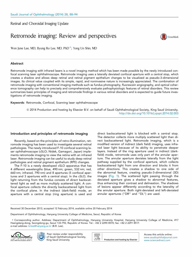
The F-10 is a newly developed cSLO apparatus that has4 different wavelengths (blue, 490 nm; green, 532 nm; red,660 nm; infrared, 790 nm) and 8 apertures (5 confocal aper-tures and 3 apertures with a central stop). In the cSLO, thelight returning from the fundus consists of direct backscat-tered light as well as more multiply scattered light. A con-focal aperture collects the directly backscattered light fromthe confocal plane. In the indirect (dark-field) mode, anaperture with a central stop (ring aperture) is used and
direct backscattered light is blocked with a central stop.The detector collects more multiply scattered light than di-rect backscattered light. Retromode imaging, which is amodified version of indirect (dark field) imaging, uses infra-red laser light because of its ability to penetrate deeperlayers. Instead of the ring aperture used in indirect (dark-field) mode, retromode uses only part of the annular aper-ture. The annular aperture deviates laterally from the lightpathway supplied by the confocal aperture, which collectsbackscattered light from one direction and blocks it fromother directions. This creates a shadow to one side ofthe abnormal feature, creating pseudo-3-dimensional (3D)images (Fig. 1). The scattered light passing through thedeviated aperture gives a shadow to abnormal features,thus enhancing their contrast and delineation. The shadowsof lesions appear differently according to the laterality ofthe annular aperture. Both right-deviated and left-deviatedannular apertures (‘‘DR’’ and ‘‘DL’’) are used.
Figure 1. Schematic mechanism underlying retromode imaging with aconfocal scanning laser ophthalmoscope. (A) Confocal mode: imagesconsist primarily of direct backscattered light from the fundus. (B) Indirect(dark-field) mode using an aperture with a central stop (ring aperture):direct backscattered light is blocked with a central stop. More multiplyscattered light from intraretinal structures is collected by the detector. (C)Retro-mode: The opening of the ring aperture is restricted and deviateslaterally from the confocal light path. Multiply scattered light from onlyone direction is collected by the detector.
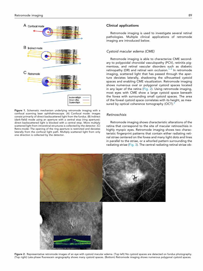
Figure 2. Representative retromode images of an eye with cystoid macular e(Top right) Late-phase fluorescein angiography shows many cystoid spaces. (B
Retromode imaging 89
Clinical applications
Retromode imaging is used to investigate several retinalpathologies. Multiple clinical applications of retromodeimaging are introduced below.
Cystoid macular edema (CME)
Retromode imaging is able to characterize CME second-ary to polypoidal choroidal vasculopathy (PCV), retinitis pig-mentosa, and retinal vascular disorders such as diabeticretinopathy (DR) and retinal vein occlusion.1–3 In retromodeimaging, scattered light that has passed through the aper-ture deviates laterally, shadowing the silhouetted cystoidspaces and enabling CME visualization. Retromode imagingshows numerous oval or polygonal cystoid spaces locatedin any layer of the retina (Fig. 2). Using retromode imaging,most eyes with CME show a large cystoid space beneaththe fovea with surrounding small cystoid spaces. The areaof the foveal cystoid space correlates with its height, as mea-sured by optical coherence tomography (OCT).2
Retinoschisis
Retromode imaging shows characteristic alterations of theretina that correspond to the site of macular retinoschisis inhighly myopic eyes. Retromode imaging shows two charac-teristic fingerprint patterns that contain either radiating reti-nal striae centered on the fovea and many light dots and linesin parallel to the striae, or a whorled pattern surrounding theradiating striae (Fig. 3). The central radiating retinal striae ob-
dema. (Top left) No cystoid spaces are detected on fundus photography.ottom) Retromode imaging shows numerous polygonal cystoid spaces.
Figure 3. Representative retromode images of an eye with outer macular retinoschisis. (Top left) Fundus photograph of the right eye of a 77-year-oldwoman showing diffuse chorioretinal atrophy in the posterior fundus. (Top and middle right) Horizontal and vertical scans across the central fovea byoptical coherence tomography (OCT) show macular retinoschisis with an inner lamellar hole in the central fovea. (Bottom) Retromode image by F10shows a fingerprint pattern (black arrowheads) consisting of central radiating retinal striae and surrounding multiple dots (arrowhead) and lines (arrow).Many lines appear in parallel or in a whorled pattern. The inner lamellar hole is observed as a circular defect at the central fovea. Data are from Am JOphthalmol (Tanaka et al.4).
90 W.J. Lee et al.
served in retromode imaging may represent the splitting ofthe horizontally oriented internal cone fibers.4
In eyes with X-linked retinoschisis, it is occasionally difficultto detect a foveal schisis ophthalmoscopically. However, thefoveal schisis is clearly delineated by retromode imaging,which also clearly delineates the stellate spoke-like fovealschisis.5
Drusen
Retromode imaging shows a pseudo-3D appearance todrusen, which is consistent with the appearance of drusenon OCT imaging (Fig. 4). Retromode imaging detects signif-icantly more subretinal deposits than conventional color fun-dus photography.6 In addition, retromode imaging detectshigher numbers of drusen than cSLO using another infraredconfocal aperture. In fact, the mean number of drusen de-tected with the ‘‘DR’’ retromode is almost two times greaterthan the number detected by color fundus photography.
Small drusen are more easily visualized with retromode imag-ing. This suggests that retromode imaging may be a sensitivemodality for the detection of drusen, especially when a pa-tient is early in the disease course and/or when the drusenare small or subtle.7
Comparing the second and first set of retromode imagesrevealed appreciable changes, such as enlargement and con-fluence of the deposits; however, no changes over time wereevident on fundus photography. Therefore, retromode imag-ing may be useful in monitoring the response of drusen to fu-ture therapeutic interventions6 as well as subtle changes andprogression of age-related macular degeneration (AMD).
Central serous chorioretinopathy (CSCR)
Retromode imaging can provide topographic informationregarding RPE alterations in CSCR; this topographic map issimilar to a surface RPE map of the posterior pole.8
Figure 4. Representative retromode images of an eye with drusen in the fellow eyes of unilateral exudative age-related macular degeneration patients.Soft drusen and hard drusen are mixed. (Top left) Fundus photography. (Topright) Retromode imaging (Bottom) Optical coherence tomography (OCT).The drusen in retromode imaging appear pseudo-3-dimensional and are clearer than in fundus photography. The OCT finding is retinal pigmentepithelium elevation, which is consistent with the appearance of drusen.
Retromode imaging 91
Retromode imaging identifies subretinal fluid (SRF) as awell-defined, circular to ovoid, translucent prominence withlow to moderate convexity and a dark shadow. Semicircularpigment epithelial detachment (PED) is identified as a well-defined, circular to slightly irregular, translucent prominencewith low to moderate convexity and a dark shadow. Low toflat PED and RPE protrusion are identified as a well- toill-defined, flat to slightly convex, slightly irregular, and trans-lucent to opaque prominences with a dark shadow.Subretinal precipitations appear as multiple small, relativelyhyperreflective dots. In cases of resolved CSCR, disruptedouter photoreceptors appear as a well-defined, ragged,plate-like surface (Fig. 5).8
Diabetic retinopathy (DR)
In the evaluation of diabetic macular edema (DME), ret-romode imaging and OCT show high agreement. AlthoughOCT is the new gold standard in evaluating DME, retro-mode imaging also allows for early DME detection. More-over, retromode imaging provides immediate visualizationof macular edema location and the extension of thickenedarea.
Retromode imaging can visualize leaking microaneurysmsas localized elevations. These elevations correspond to mic-roaneurysms that show significant dye diffusion in late-phasefluorescein angiography (FA).3 Retromode imaging may beuseful in evaluating neovascular vessels and fibrovascularmembranes and determining precise retinal changes in prolif-erative DR.9
Subthreshold laser scar
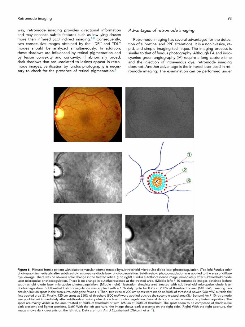
Retromode imaging is useful in detecting sites of sub-threshold micropulse laser application that cannot be de-tected by color fundus photography (Fig. 6). The darkspots detected by retromode imaging are probably relatedto swelling of the RPE after laser application. Since
subthreshold diode laser micropulse photocoagulation isselective for the RPE, the dark spots are assumed tobe related to structural RPE changes. Retromode imagingprovides useful confirmation of the invisible spotscreated by subthreshold diode laser micropulsephotocoagulation.10
Retinal dystrophies
Retromode imaging is able to detect abnormalities in ret-inal dystrophies, including Best vitelliform macular dystrophy,autosomal recessive Stargardt disease (fundus flavimacula-tus), pattern dystrophy of the RPE, choroideremia, benignconcentric annular macular dystrophy, and Bietti crystallinedystrophy. The main finding is a pseudo-3D pattern of allthe lesions at the posterior pole. Any accumulation of mate-rial within the retina appears as an elevated area with variedshapes and sizes, showing irregular and darker borders. Onthe other hand, atrophic regions are accurately outlined bythe precise visualization of the choroidal vasculature, bothin the macula and, in cases where the fovea is spared, outsidethe macular region as well.11,12
Other uses
Retromode imaging is able to clearly visualize the mor-phological features of PCV, including polypoidal lesions andbranching vascular networks.13 Retromode imaging is alsouseful in detecting retinal changes secondary to exudativeAMD associated with CNV, particularly CME.14
Perspectives
Directionality of retromode imaging
The interpretation of lesion morphologies seen with ret-romode imaging requires attention to the dark shadowssurrounding specific lesions, because they appear as dark
Figure 5. Representative retromode images of eyes with central serous chorioretinopathy (CSCR): a case series of acute CSCR. Various alterations in theretinal pigment epithelium (RPE) are observed using retro-mode imaging and spectral-domain optical coherence tomography (OCT). (Top left)Subretinal fluid (SRF) in OCT appears as a well-defined, convex, circular, and translucent prominence with a dark shadow in retromode images (whitearrowheads). The vertex of the SRF is the highly reflective focal spot (yellow arrow) in retromode images. Small pigment epithelial detachments (PED)seen on OCT are not observed in this retromode image because of the SRF’s blocking effect. (Top right) Low to flat PED in OCT (white arrow) appears asa relatively well-defined, flat-convex, slightly irregular, translucent prominence with a dark shadow (white arrow) in retromode images. Even if the PED islocated within the SRF, it can be seen clearly. (Middle left) Semicircular PED within the SRF seen on OCT appears as a well-defined, semicircular-convex,circular, and translucent prominence with a dark shadow (white arrow) in retromode images. A small PED away from the SRF is also observed inretromode imaging (white arrowhead). (Middle right) RPE protrusion in OCT appears as a relatively ill-defined, flat-convex, irregular, and opaqueprominence with a dark shadow in retromode images (white arrow). (Bottom left) No PED is detected in whole OCT scans obtained by a 6 by 6 mmvolume scan protocol. However, retro-mode imaging reveals multiple PEDs located at the margin of the SRF (white arrows). (Bottom right) Bullous SRFand small subfoveal PEDs are observed in OCT. Retromode imaging shows the extent of the SRF (white arrowheads) and multiple PEDs alongside theSRF (white arrows). Data are from Am J Ophthalmol (Shin et al.8).
92 W.J. Lee et al.
crescent shadows in the opposite direction of the annularaperture (‘‘DR’’ mode or ‘‘DL’’ mode).8 For example,elevated lesions such as PED are composed of lighterportions and shadows such as dark crescents. The darkcrescents represent a concave border between the flatRPE area and the elevated PED, while the lighter portions
represent the convex area of the elevated PED.8 Thus, thedirection of the deviated aperture and the positions of thedark and light portions of the target lesion should be con-sidered when interpreting retromode images. Dependingon whether the ‘‘DR’’ or ‘‘DL’’ mode is used, convexlesions may appear as convex or concave patterns. In this
Retromode imaging 93
way, retromode imaging provides directional informationand may enhance subtle features such as low-lying drusenmore than infrared SLO indirect imaging.6,8 Consequently,two consecutive images obtained by the ‘‘DR’’ and ‘‘DL’’modes should be analyzed simultaneously. In addition,these shadows are influenced by retinal pigmentation andby lesion convexity and concavity. If abnormally broad,dark shadows that are unrelated to lesions appear in retro-mode images, verification by fundus photography is neces-sary to check for the presence of retinal pigmentation.8
Figure 6. Pictures from a patient with diabetic macular edema treated by subtphotograph immediately after subthreshold micropulse diode laser photocoagdye leakage. There was no obvious color change in the treated retina. (Top riglaser micropulse photocoagulation. There is no change in autofluorescence asubthreshold diode laser micropulse photocoagulation. (Middle right) Illustphotocoagulation. Subthreshold photocoagulation was applied with a 15% dcircular 200 um spots in the area surrounding the fovea (1). Then, two circular 2first treated area (2). Finally, 125 um spots at 250% of threshold (800 mW) wereimage obtained immediately after subthreshold micropulse diode laser photospots are mainly visible in the area treated at 300% of threshold or with 125 udark crescent and lighter portions. (Left) With the left aperture, the image shimage shows dark crescents on the left side. Data are from Am J Ophthalmo
Advantages of retromode imaging
Retromode imaging has several advantages for the detec-tion of subretinal and RPE alterations. It is a noninvasive, ra-pid, and simple imaging technique. The imaging process issimilar to that of fundus photography. Although FA and indo-cyanine green angiography (IA) require a long capture timeand the injection of intravenous dye, retromode imagingdoes not. Another advantage is the infrared laser used in ret-romode imaging. The examination can be performed under
hreshold micropulse diode laser photocoagulation. (Top left) Fundus colorulation. Subthreshold photocoagulation was applied to the area of diffuseht) Fundus autofluorescence image immediately after subthreshold diodet the treated area. (Middle left) F-10 retromode images obtained beforeration showing area treated with subthreshold micropulse diode laseruty cycle for 0.2 s at 200% of threshold power (640 mW), creating two
00 um spots were made at 300% of threshold power (960 mW) outside theapplied outside the second treated area (3). (Bottom) An F-10 retromode
coagulation. Several dark spots can be seen after photocoagulation. Them at 250% of threshold. The spots seem to be composed of shadow-likeows dark crescents on the right side. (Right) With the right aperture, thel (Ohkoshi et al.10).
94 W.J. Lee et al.
nonmydriatic conditions or even in cases with significant lensopacity, due to the properties of the long-wavelength laser.Moreover, patients may feel more comfortable during theexamination because the infrared light is less irritating thanthe blue light used in FA.8
Retromode imaging also provides pseudo-3D images ofthe lesions on the en face plane in a single image, which helpsto evaluate the spatial distribution of lesions in the posteriorpole of the fundus.
Limitation of retromode imaging
With respect to the use of retromode imaging for thedetection of abnormal features, several issues should be con-sidered. First, retromode imaging is currently available onlywith use of the F-10 microscope. Second, this technique can-not replace OCT, FA, and IA in evaluating various retinal dis-orders. OCT is still the gold standard for diagnosinganatomic lesions in retinal and subretinal layers. Unlike FAand IA, retromode imaging cannot be used to describe thedisease activity of various retinal disorders, and it is difficultto make treatment decisions using retromode imaging alone.Therefore, retromode imaging may be helpful as an imagingtechnique that complements OCT, FA and IA. Third, severalprevious studies with retromode imaging described the rela-tionship between the retromode imaging and that of retinaldisorders; however, these experiments were not designedto determine the mechanism causing the appearance of theretinal disorders.4 Fourth, in the absence of histological con-firmation, we cannot necessarily conclude that all abnormali-ties seen by this new imaging strategy are in fact present andrelevant. For example, retromode imaging alone is unable todifferentiate flat PED from RPE irregularities.8 Fifth, this non-invasive imaging technique is helpful in determining both thepresence and the extent of abnormal features in the posteriorpole, but is not able to localize the exact depth of the lesionswithin the retinal layers. This might be explained by the opti-cal characteristics of the system, which are unable to separatethe back-scattered light reflected from the retina, choroid,and sclera.
Conclusions
Retromode imaging is a new technique capable of provid-ing comprehensive topographic information related to thedeep retina and RPE alterations. However, the investigationof retromode imaging is in its earliest stages, and there areshortcomings in the interpretation of these findings. Thus,the combination of retromode imaging and other imagingmodalities such as OCT and FA can help to precisely andcomprehensively evaluate pathophysiologic features of reti-nal disorders. This review is expected to help guide future
investigations of retromode imaging in various retinaldisorders.
Conflict of interest
The authors declared that there is no conflict of interest.
References
1. Yamamoto M, Tsujikawa A, Mizukami S, Miyoshi N, Yoshimura N.Cystoid macular edema in polypoidal choroidal vasculopathy viewedby a scanning laser ophthalmoscope: CME in PCV viewed by SLO. IntOphthalmol 2009;29(6):503–6.
2. Yamamoto M, Mizukami S, Tsujikawa A, Miyoshi N, Yoshimura N.Visualization of cystoid macular oedema using a scanning laserophthalmoscope in the retro-mode. Clin Exp Ophthalmol 2010;38(1):27–36.
3. Vujosevic S, Trento B, Bottega E, Urban F, Pilotto E, Midena E.Scanning laser ophthalmoscopy in the retromode in diabetic macularoedema. Acta Ophthalmol 2012;90(5), e374-80.
4. Tanaka Y, Shimada N, Ohno-Matsui K, Hayashi W W, Hayashi K,Moriyama M, et al. Retromode retinal imaging of macularretinoschisis in highly myopic eyes. Am J Ophthalmol 2010;149(4):635–40, e1.
5. Katome T, Mitamura Y, Nagasawa T, Eguchi H, Naito T. Scanninglaser ophthalmoscope retro-mode imaging of foveal schisis in eyeswith X-linked retinoschisis. Clin Exp Ophthalmol 2012;40(1), e120-2.
6. Acton JH, Cubbidge RP, King H, Galsworthy P, Gibson JM. Drusendetection in retro-mode imaging by a scanning laser ophthalmoscope.Acta Ophthalmol 2011;89(5), e404-11.
8. Shin YU, Lee BR. Retro-mode imaging for retinal pigment epitheliumalterations in central serous chorioretinopathy. Am J Ophthalmol2012;154(1):155–63, e4.
9. Suzuma K, Tsuiki E, Matsumoto M, Fujikawa A, Kitaoka T. Retro-mode imaging of fibrovascular membrane in proliferative diabeticretinopathy after intravitreal bevacizumab injection. Clin Ophthalmol2011;5:897–900.
10. Ohkoshi K, Tsuiki E, Kitaoka T, Yamaguchi T. Visualization ofsubthreshold micropulse diode laser photocoagulation by scanninglaser ophthalmoscopy in the retro mode. Am J Ophthalmol2010;150(6):856–62.
11. Maurizio BP, Pierluigi I, Stelios K, Stefano V, Marialucia C, Ilaria Z,et al. Retro-mode imaging and fundus autofluorescence withscanning laser ophthalmoscope of retinal dystrophies. BMCOphthalmol 2012;12:8.
12. Parravano M, Sciamanna M, Giorno P, Boninfante A, Varano M. Bietticrystalline dystrophy: a morpho-functional evaluation. DocOphthalmol 2012;124(1):73–7.
13. Zeng R, Zhang X, Su Y, Li M, Wu K, Wen F. The noninvasive retro-mode imaging modality of confocal scanning laser ophthalmoscopyin polypoidal choroidal vasculopathy: a preliminary application. PLoSOne 2013;8(9):e75711.
14. Pilotto E, Sportiello P, Alemany-Rubio E, Vujosevic S, Segalina S,Fregona I, et al. Confocal scanning laser ophthalmoscope in theretromode imaging modality in exudative age-related maculardegeneration. Graefes Arch Clin Exp Ophthalmol 2013;251(1):27–34.


![Spectrofl uorometer - GrupoBios · Calibration Curve of Fluorescein Solutions Spectra of Fluorescein Solutions Spectrum of quinine sulfate solution Wavelength [nm] 300 400 500 600](https://static.documents.pub/doc/80x56/5fb614bb5457d74a9a1fd826/spectrofl-uorometer-grupobios-calibration-curve-of-fluorescein-solutions-spectra.jpg)


