IM3075 11/2020 REV05 SPEEDTEC 320CP SPEEDTEC 320CP Push Pull OPERATOR’S MANUAL ENGLISH Lincoln Electric Bester Sp. z o.o. ul. Jana III Sobieskiego 19A, 58-260 Bielawa, Poland www.lincolnelectric.eu
Transcript
IM3075 11/2020 REV05
SPEEDTEC 320CP SPEEDTEC 320CP Push Pull
OPERATOR’S MANUAL
ENGLISH
Lincoln Electric Bester Sp. z o.o.
ul. Jana III Sobieskiego 19A, 58-260 Bielawa, Poland www.lincolnelectric.eu
English I English
12/05
THANKS! For having chosen the QUALITY of the Lincoln Electric products. Please Examine Package and Equipment for Damage. Claims for material damaged in shipment must be notified
immediately to the dealer. For future reference record in the table below your equipment identification information. Model Name, Code &
Serial Number can be found on the machine rating plate.
INDEX Technical Specifications ...................................................................................................................................................... 1 ECO design information ...................................................................................................................................................... 2 Electromagnetic Compatibility (EMC) .................................................................................................................................. 4 Safety .................................................................................................................................................................................. 5 Installation and Operator Instructions .................................................................................................................................. 7 WEEE ............................................................................................................................................................................... 24 Spare Parts ....................................................................................................................................................................... 24 REACh .............................................................................................................................................................................. 24 Authorized Service Shops Location .................................................................................................................................. 24 Electrical Schematic .......................................................................................................................................................... 24 Accessories ....................................................................................................................................................................... 25
English 1 English
Technical Specifications
NAME INDEX
SPEEDTEC 320CP K14168-1
SPEEDTEC 320CP PUSH PULL K14168-2
PRIMARY SIDE
Primary power supply 400 V +/-20%
Primary power supply frequency 50/60 Hz
Effective primary consumption 12 A
Maximum primary consumption 18,7 A
Fuse primary 16 A Gg
Maximum apparent power 13,1 kVA
Maximum active power 12,1 kW
Active power in standby (IDLE) 26 W
Efficiency at maximum current 0,86
Power factor at maximum current 0,91
Cos Phi 0,99
SECONDARY SIDE
No load voltage (according standard) 74 V
Welding range MIG 10 V / 50 V
Welding range MMA 15 A / 320 A
Duty cycle at 100% (10 min cycle at 40°C) 220 A
Duty cycle at 60% (6 min cycle at 40°C) 280 A MIG / 270 A MMA
Duty cycle at maximum current at 40°C 320 A (40%)
WIRE FEEDER
Rollers plate 4 rollers
Wire feeding speed 0,5 – 25,0 m / mn
Wire diameter usable 0.6 to 1,2 mm
Weight, type, size of wire spool 300 mm / 20Kg maximum
Maximum pressure of gas 5 bar
MISCELLEANOUS
Dimensions (Lxwxh) 743 x 335,4 x 533,75 mm
Weight 37 kg
Weight with spool 20kg 58,4 kg
Operating temperature - 10°C/+40°C
Storage temperature - 20°C/+55°C
Torch connection “European type”
Protection index IP 23
Insulation class H
Standard 60974-1, 60974-5, 60974-10
English 2 English
ECO design information The equipment has been designed in order to be compliant with the Directive 2009/125/EC and the Regulation 2019/1784/EU. Efficiency and idle power consumption:
Index Name Efficiency when max power
consumption / Idle power consumption Equivalent model
K14168-1 SPEEDTEC 320CP 85% / 28W No equivalent model
K14168-2 SPEEDTEC 320CP PUSH
PULL 85% / 28W No equivalent model
Idle state occurs under the condition specified in below table
IDLE STATE
Condition Presence
MIG mode X
TIG mode
STICK mode
After 30 minutes of non-working
Fan off X
The value of efficiency and consumption in idle state have been measured by method and conditions defined in the product standard EN 60974-1:20XX. Manufacturer’s name, product name, code number, product number, serial number and date of production can be read from rating plate.
XXXXXXXXXXCode: XXXXX XXXXXX-X
S/N: P1YYMMXXXXX
1 2
3 4
5
P1 YY MM XXXXX
5A5A 5B 5D5C
XXXXXXX
Where:
1- Manufacturer name and address 2- Product name 3- Code number 4- Product number 5- Serial number
5A- country of production 5B- year of production 5C- month of production 5D- progressive number different for each machine
English 3 English
Typical gas usage for MIG/MAG equipment:
Material type Wire
diameter [mm]
DC electrode positive Wire Feeding
[m/min] Shielding Gas
Gas flow [l/min] Current
[A] Voltage
[V] Carbon, low alloy steel
0,9 ÷ 1,1 95 ÷ 200 18 ÷ 22 3,5 – 6,5 Ar 75%, CO2 25% 12
Tig Process: In TIG welding process, gas usage depends on cross-sectional area of the nozzle. For commonly used torches: Helium: 14-24 l/min Argon: 7-16 l/min Notice: Excessive flow rates causes turbulence in the gas stream which may aspirate atmospheric contamination into the welding pool. Notice: A cross wind or draft moving can disrupt the shielding gas coverage, in the interest of saving of protective gas use screen to block air flow.
End of life
At end of life of product, it has to be disposal for recycling in accordance with Directive 2012/19/EU (WEEE), information about the dismantling of product and Critical Raw Material (CRM) present in the product, can be found at https://www.lincolnelectric.com/en-gb/support/Pages/operator-manuals-eu.aspx
English 4 English
Electromagnetic Compatibility (EMC) 01/11
This machine has been designed in accordance with all relevant directives and standards. However, it may still generate electromagnetic disturbances that can affect other systems like telecommunications (telephone, radio, and television) or other safety systems. These disturbances can cause safety problems in the affected systems. Read and understand this section to eliminate or reduce the amount of electromagnetic disturbance generated by this machine.
WARNING
This machine has been designed to operate in an industrial area. To operate in a domestic area it is necessary to observe particular precautions to eliminate possible electromagnetic disturbances. The operator must install and operate this equipment as described in this manual. If any electromagnetic disturbances are detected the operator must put in place corrective actions to eliminate these disturbances with, if necessary, assistance from Lincoln Electric. Provided that the public low voltage system impedance at the point of common coupling is lower than 97mΩ, this equipment is compliant with IEC 61000-3-11 and 61000-3-12 and can be connected to public low voltage systems. It is the responsibility of the installer or user of the equipment to ensure by consultation with the distribution network operator if necessary, that the system impedance complies with the impedance restrictions. Before installing the machine, the operator must check the work area for any devices that may malfunction because of electromagnetic disturbances. Consider the following. Input and output cables, control cables, and telephone cables that are in or adjacent to the work area and the
machine. Radio and/or television transmitters and receivers. Computers or computer controlled equipment. Safety and control equipment for industrial processes. Equipment for calibration and measurement. Personal medical devices like pacemakers and hearing aids. Check the electromagnetic immunity for equipment operating in or near the work area. The operator must be sure
that all equipment in the area is compatible. This may require additional protection measures. The dimensions of the work area to consider will depend on the construction of the area and other activities that are
taking place. Consider the following guidelines to reduce electromagnetic emissions from the machine. Connect the machine to the input supply according to this manual. If disturbances occur if may be necessary to take
additional precautions such as filtering the input supply. The output cables should be kept as short as possible and should be positioned together. If possible connect the
work piece to ground in order to reduce the electromagnetic emissions. The operator must check that connecting the work piece to ground does not cause problems or unsafe operating conditions for personnel and equipment.
Shielding of cables in the work area can reduce electromagnetic emissions. This may be necessary for special applications.
WARNING EMC classification of this product is class A in accordance with electromagnetic compatibility standard EN 60974-10 and therefore the product is designed to be used in an industrial environment only.
WARNING The Class A equipment is not intended for use in residential locations where the electrical power is provided by the public low-voltage supply system. There can be potential difficulties in ensuring electromagnetic compatibility in those locations, due to conducted as well as radio-frequency disturbances.
English 5 English
Safety 01/11
WARNING
This equipment must be used by qualified personnel. Be sure that all installation, operation, maintenance and repair procedures are performed only by qualified person. Read and understand this manual before operating this equipment. Failure to follow the instructions in this manual could cause serious personal injury, loss of life, or damage to this equipment. Read and understand the following explanations of the warning symbols. Lincoln Electric is not responsible for damages caused by improper installation, improper care or abnormal operation.
WARNING: This symbol indicates that instructions must be followed to avoid serious personal injury, loss of life, or damage to this equipment. Protect yourself and others from possible serious injury or death.
READ AND UNDERSTAND INSTRUCTIONS: Read and understand this manual before operating this equipment. Arc welding can be hazardous. Failure to follow the instructions in this manual could cause serious personal injury, loss of life, or damage to this equipment.
ELECTRIC SHOCK CAN KILL: Welding equipment generates high voltages. Do not touch the electrode, work clamp, or connected work pieces when this equipment is on. Insulate yourself from the electrode, work clamp, and connected work pieces.
ELECTRICALLY POWERED EQUIPMENT: Turn off input power using the disconnect switch at the fuse box before working on this equipment. Ground this equipment in accordance with local electrical regulations.
ELECTRICALLY POWERED EQUIPMENT: Regularly inspect the input, electrode, and work clamp cables. If any insulation damage exists replace the cable immediately. Do not place the electrode holder directly on the welding table or any other surface in contact with the work clamp to avoid the risk of accidental arc ignition.
ELECTRIC AND MAGNETIC FIELDS MAY BE DANGEROUS: Electric current flowing through any conductor creates electric and magnetic fields (EMF). EMF fields may interfere with some pacemakers, and welders having a pacemaker shall consult their physician before operating this equipment.
CE COMPLIANCE: This equipment complies with the European Community Directives.
ARTIFICIAL OPTICAL RADIATION: According with the requirements in 2006/25/EC Directive and EN 12198 Standard, the equipment is a category 2. It makes mandatory the adoption of Personal Protective Equipment (PPE) having filter with a protection degree up to a maximum of 15, as required by EN169 Standard.
FUMES AND GASES CAN BE DANGEROUS: Welding may produce fumes and gases hazardous to health. Avoid breathing these fumes and gases. To avoid these dangers the operator must use enough ventilation or exhaust to keep fumes and gases away from the breathing zone.
ARC RAYS CAN BURN: Use a shield with the proper filter and cover plates to protect your eyes from sparks and the rays of the arc when welding or observing. Use suitable clothing made from durable flame-resistant material to protect you skin and that of your helpers. Protect other nearby personnel with suitable, non-flammable screening and warn them not to watch the arc nor expose themselves to the arc.
English 6 English
WELDING SPARKS CAN CAUSE FIRE OR EXPLOSION: Remove fire hazards from the welding area and have a fire extinguisher readily available. Welding sparks and hot materials from the welding process can easily go through small cracks and openings to adjacent areas. Do not weld on any tanks, drums, containers, or material until the proper steps have been taken to insure that no flammable or toxic vapors will be present. Never operate this equipment when flammable gases, vapors or liquid combustibles are present.
WELDED MATERIALS CAN BURN: Welding generates a large amount of heat. Hot surfaces and materials in work area can cause serious burns. Use gloves and pliers when touching or moving materials in the work area.
CYLINDER MAY EXPLODE IF DAMAGED: Use only compressed gas cylinders containing the correct shielding gas for the process used and properly operating regulators designed for the gas and pressure used. Always keep cylinders in an upright position securely chained to a fixed support. Do not move or transport gas cylinders with the protection cap removed. Do not allow the electrode, electrode holder, work clamp or any other electrically live part to touch a gas cylinder. Gas cylinders must be located away from areas where they may be subjected to physical damage or the welding process including sparks and heat sources.
HF CAUTION: The high frequency used for contact-free ignition with TIG (GTAW) welding, can interfere with the operation of insufficiently shielded computer equipment, EDP centers and industrial robots, even causing complete system breakdown. TIG (GTAW) welding may interfere with electronic telephone networks and with radio and TV reception.
EQUIPMENT WEIGHT OVER 30kg: Move this equipment with care and with the help of another person. Lifting may be dangerous for your physical health.
NOISE APPEARES DURING WELDING CAN BE HARMFUL: Welding arc can cause noise with high level of 85dB for 8-hour week day. Welders operating welding machines are obligated to wear the proper ear protectors. Employers are obligated to carry examinations and measurements of health harmful factors.
SAFETY MARK: This equipment is suitable for supplying power for welding operations carried out in an environment with increased hazard of electric shock.
The manufacturer reserves the right to make changes and/or improvements in design without upgrade at the same time the operator’s manual.
English 7 English
Installation and Operator Instructions
General description SPEEDTEC 320CP / SPEEDTEC320CP PP is a manual welding set that enables the following:
MIG-MAG welding with short arc, speed short arc, spray-arc, normal pulsed mode using currents from 15A to 320A.
SPEEDTEC 320CP / PP work with the water cooler COOLARC 46.
Feeding different types of wire - steel, stainless steel, aluminum and special wires - solid and cored wires - diameters from 0.6-0.8-1.0-1.2 mm
Welding set components The welding set consists of 4 main components: 1. power source including its primary cable (5m) without
plug 2. gas hose kit assembly (2m) 3. work lead (3m) 4. rolls for solid wire V1.0/V1.2 5. USB key containing Instruction Manual Recommended equipment, which can be bought by user, was mentioned in the chapter "Accessories". Read this entire section before installation or operation of the machine.
WARNING The plastic handles are not intended for slinging the set. Stability of the equipment is guaranteed only for an incline of maximum 15°.
Location and Environment This machine will operate in harsh environments. However, it is important that simple preventative measures are followed to assure long life and reliable operation. Do not use this machine for pipe thawing. This machine must be located where there is free
circulation of clean air without restrictions for air movement to and from the air vents. Do not cover the machine with paper, cloth or rags when switched on.
Dirt and dust that can be drawn into the machine should be kept to a minimum.
This machine has a protection rating of IP23. Keep it dry when possible and do not place it on wet ground or in puddles.
Locate the machine away from radio controlled machinery. Normal operation may adversely affect the operation of nearby radio controlled machinery, which may result in injury or equipment damage. Read the section on electromagnetic compatibility in this manual.
Do not operate in areas with an ambient temperature greater than 40°C.
Duty cycle and overheating Duty cycle is the percentage of 10 minutes at 40°C
ambient temperature that the unit can weld at its rated output without overheating.
If the unit overheats, the output stops and the over temperature light comes On. To correct the situation, wait fifteen minutes for unit to cool.
Reduce amperage, voltage or duty cycle before starting to weld again
Starting up The power source is composed with:
1. Front panel display 2. European plug for torch 3. Additional plug for 2 potentiometers torch 4. Plug for ground cable and polarity inversion 5. Protection door for wire feeder section 6. Spool axle, shaft, axle nut 7. Gas purge button 8. Cold wire feeding button 9. Wire driver
6
5
7
8
9
1
4
2
3
English 8 English
Input Supply Connection
WARNING Only a qualified electrician can connect the welding machine to the supply network. Installation the outlet plug to power lead and connecting the welding machine had to be made in accordance with the appropriate National Electrical Code and local regulations. Check the input voltage, phase, and frequency supplied to this machine before turning it on. Verify the connection of grounding wires from the machine to the input source. SPEEDTEC 320CP / PP can only be connected to a mating grounded receptacle. Input voltages is 3x400V 50/60Hz. For more information about input supply refer to the technical specification section of this manual and to the rating plate of the machine. Make sure that the amount of mains power available from the input supply is adequate for normal operation of the machine. The type of protection and cable sizes are indicated in the technical specification section of this manual.
WARNING
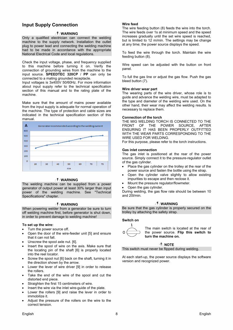
The welding machine can be supplied from a power generator of output power at least 30% larger than input power of the welding machine. See "Technical Specifications" chapter.
WARNING When powering welder from a generator be sure to turn off welding machine first, before generator is shut down, in order to prevent damage to welding machine! To set up the wire: Turn the power source off. Open the door of the wire-feeder unit [5] and ensure
that it can not fall. Unscrew the spool axle nut. [6]. Insert the spool of wire on the axis. Make sure that
the locating pin of the shaft [6] is properly located into the reel locator.
Screw the spool nut [6] back on the shaft, turning it in the direction shown by the arrow.
Lower the lever of wire driver [9] in order to release the rollers.
Take the end of the wire of the spool and cut the distorted end piece.
Straighten the first 15 centimeters of wire. Insert the wire via the inlet wire-guide of the plate. Lower the rollers [9] and raise the lever in order to
immobilize it. Adjust the pressure of the rollers on the wire to the
correct tension.
Wire feed The wire feeding button (8) feeds the wire into the torch. The wire feeds over 1s at minimum speed and the speed increases gradually until the set wire speed is reached, but is limited to 12 m/min. The settings may be change at any time; the power source displays the speed. To feed the wire through the torch. Maintain the wire feeding button (8). Wire speed can be adjusted with the button on front panel. To full the gas line or adjust the gas flow. Push the gas bleed button (7). Wire driver wear part The wearing parts of the wire driver, whose role is to guide and advance the welding wire, must be adapted to the type and diameter of the welding wire used. On the other hand, their wear may affect the welding results. Is necessary to replace them. Connection of the torch THE MIG WELDING TORCH IS CONNECTED TO THE FRONT OF THE POWER SOURCE, AFTER ENSURING IT HAS BEEN PROPERLY OUTFITTED WITH THE WEAR PARTS CORRESPONDING TO THE WIRE USED FOR WELDING. For this purpose, please refer to the torch instructions. Gas inlet connection The gas inlet is positioned at the rear of the power source. Simply connect it to the pressure-regulator outlet of the gas cylinder. Place the gas cylinder on the trolley at the rear of the
power source and fasten the bottle using the strap. Open the cylinder valve slightly to allow existing
impurities to escape and then reclose it. Mount the pressure regulator/flowmeter. Open the gas cylinder. During welding, the gas flow rate should be between 10 and 20l/min.
WARNING Be sure that the gas cylinder is properly secured on the trolley by attaching the safety strap. Switch on
The main switch is located at the rear of the power source. Flip this switch to turn the machine on.
NOTE
This switch must never be flipped during welding. At each start-up, the power source displays the software version and recognized power.
English 9 English
Instructions for use Front panel functions
Left display: Voltage, Right display: Current/ wire speed /wire thickness 1 Display for selection of welding mode 2 Selector button for welding mode 3 Selector switch for welding process 4 Measurement indicator of displayed values (pre-welding, welding and 5 post-welding data) Led indicator for program mode 6 Encoder voltage setup and navigation 7 Encoder for current, wire speed, metal sheet thickness setup and navigation 8 Display mode indicator current, wire speed, metal sheet thickness 9 Selector button for pre-display and program management 10 Selector switch for type of gas, wire diameter and type of welding wire 11
10
9
5
6 7
1
2
3
4
8
1
11
11
11
English 10 English
Calibrate the power source
Step 1: Turn the wire diameter switch to position
and press the to access the COnFIG Setup screen. Step 2: Select the CaL parameter with the left-hand encoder and select On with the right-hand encoder.
Step 3: Press the on the front panel. The display unit indicates triGEr. Step 4: Remove the torch nozzle. Step 5: Cut the wire. Step 6: Place the piece in contact with the contact tube. Step 7: Press the trigger. Step 8: The display will indicate the value of L (cable inductance). Step 9: Display the value of R using the right-hand encoder (cable resistance).
Step 10: Exit Setup.
WARNING When starting up for the first time, the calibration is an unavoidable step to achieve quality welding. If polarity is reversed, this step must be repeated
Display and use Synergic mode The Current, Voltage and Thickness values listed for each wire feed speed setting are provided for information purposes only. They correspond to measurements under given operating conditions, such as position, length of the end section (flat position welding, butt welding). The units current/voltage displayed correspond to the average measured values, and they may differ from the theoretical values. Measurement indicator of displayed values: OFF: pre-welding display of instructions. ON: Display of measurements (average values). Flashing: Measurements during welding. Selection of wire, diameter, gas, welding process Select the type of wire, the wire diameter, the used welding gas and welding process by turning the appropriate switch. Selection of the material will determine the available values for diameter, gas and processes. If synergy doesn’t exist, power source displays nOt SYn,GAS SYn,DdIA SYn,or Pro SYn. Selection of welding mode, arc length and pre-welding display Select welding mode 2S, 4S, spot, synergic and manual
by pressing . Arc length can be adjusted with left encoder (7) and pre-welding display adjustment is performed with right encoder (8). The selection of pre-
welding preset is performed with press button .
Manual mode This is the disengaged mode of the welding machine. Adjustable parameters for it are wire speed, arc voltage and fine setting. In this mode, only the wire speed value is displayed. Have to select wire diameter, gas and welding process before starting welding.
SETUP mode Accessing the SETUP: The SETUP screen can only be accessed when no welding is in progress, by setting the Wire Diameter selector on the front panel to position 1. It consist in two pull-down menu: 'CYCLE’ Setting for the cycle phases. Refer to table for detail. ‘COnFIG’ Power source configuration Configuring the SETUP: In SETUP position, select CYCLE or COnFIG by
pressing . Turn the left-hand encoder to scroll through the available parameters. Turn the right-hand encoder to set their value. No welding start. All the changes are saved on exiting the SETUP menu.
English 11 English
List of accessible parameters in COnFIG menu Left
display Right display Step Default Description
GrE On -;OFF – Aut Aut
Configuration of the Water Cooling Unit. 3 possibles states : - On : Forced on, watercooler is always activated - OFF : Forced off, watercooler is always deactivated - Aut : Automatic mode, Watercooler works when
according need
ScU nc – no - OFF OFF
Security of water cooling. 3 possible states : - nc : Normally closed, - no : Normally open, - OFF : Deactivate
Unit US – CE CE Unit displayed for wire speed and thickness:
- US : inch unit - CE : meter unit
CPt OFF– 0,01 – 1,00 0,01 s 0,30 Trigger holding time in order to call program (Only in 2S welding mode). Can be used only for welding program from 50 to 99.
PGM no – yES No Activate / deactivate program management mode
PGA OFF – ;
000 – 020 % 1% OFF
Use to setup available adjustment range of the following parameters: wire speed, arc voltage, arc dynamics, pulse fine-setting. Use only when program management is activated and programs are locked.
AdJj Loc – rC Loc Select adjustment Wire speed and arc voltage :
- Loc : Local on the power source - rC : remote Control or torch potentiometer
CAL OFF – on OFF Calibration of torch & ground harness L 0 – 50 1 uH 14 Cable choke setting / display r 0 – 50 1 8 Cable resistor setting / display
SoF no – yES No Software update mode.
FAC no – yES No
Factory settings reset. Pressing YeS will cause a reset of the
parameters to factory defaults when exit .
List of accessible parameters in CYCLE menu Left
display Right display Step Default Description
tPt 00.5 – 10.0 0,1 s 0,5 Spot time. In Spot mode and in Manual mode, the Hot Start, Downslope and sequencer settings cannot be changed
PrG 00.0 – 10.0 0,1 s 0,5 Pre-gas time tHS OFF – 00.1 – 10.0 0,1 s 0,1 Hot start time IHS -- 70 – 70 1 % 30 Hot start current (wire speed). X% the welding current UHS -- 70 – 70 1 % 0 Hot start voltage X% the arc voltage
dYn --10 + 10 --20 + 20
1 % 0 Fine setting in short arc
rFP --10 + 10 --20 + 20
1 % 0 Fine setting in pulse
dyA 00 – 100 1 50 Arc striking dynamics at electrode tSE OFF – 0.01 – 2.50 0,01 s OFF Sequencer time (Sequencer, only in synergic mode) ISE ---90 + 90 1 % 30 Sequencer current level. X% the welding current dSt OFF – 00.1 – 05.0 0,1 s OFF Down-slope time
DdSI -- 70 – 00.0 1 % -- 30 Down-slope current (wire speed). X% the welding current dSU -- 70 – 70 1 % 0 Down-slope voltage. X% the arc voltage Pr_ 0.00 – 0.20 0,01 s 0,05 Anti-stick time PrS Nno – yES no Pr-Spray activation PoG 00.0 – 10.0 0,05 s 0,05 Post-gas time
English 12 English
Program management SPEEDTEC 320CP / PP allows creating, storing and modifying up to 99 welding programs directly on front panel from program 01 to program 99. This function is activated by moving parameter PGM from no to YES in COnFIG menu. P00 is the working program in any state. (Program management mode activated or deactivated). When power source is working on this program, the Led indicator “JOB” is switched off. All commutators are accessible in this mode, so it will be used to set programs. P01 to P99 are program saved, only if program management mode is activated. When power source is working on these programs, the led indicator “JOB” is switched on. In this mode, commutators welding process, wire diameter, gas and metal are not available. When a program selected has been modified, the indicator “JOB” blinks. Create and save a program: These paragraph explains how to create, modify and save a welding program. Hereunder is explained the common menu used.
1. Activate program management mode:
PGM put YES exit 2. Set your program with the 4 commutators (4) and
(11) then long push 3. Screen displays message as following:
Function selection: rEC: Save program Ld: Load program cod: Activate locking code
Validate action in progress
Cancel action in progress
Program number selection from P01 to P99. P00: Cancel program mode
Program number selection.from P01 to P99. P00: Cancel program mode
English 13 English
Program call with trigger This function allows to chain from 2 to 10 programs. This function is available in 4S welding mode only and program management mode has to be activated Program chaining: The function program call works with programs from P50 to P99 by ten. P50P59 ; P60P69 ; P70P79 ; P80P89 ;
P90P99 Select first program with which you want to begin your chain. Then during welding, each time you will push trigger, program will change. To chain less than ten programs, in the program following end of loop desired put a different parameter (As synergy or welding cycle). It is possible to setup time of trigger push to detect
change of program chain: CPT put value
from 1 to 100 exit Example: Create a program list from P50 to P55 (6 programs). In program P56, put different welding cycle or synergy than P55 in order to finish chain Select program P50 (First program for start of welding Start welding Each time trigger will be pushed, power source will change program until P55. When chain is finished, power source will restart to P50.
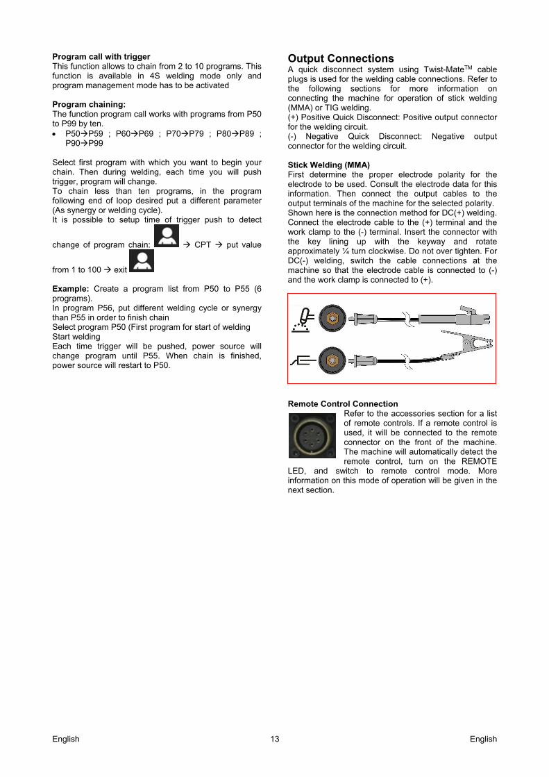
Output Connections A quick disconnect system using Twist-MateTM cable plugs is used for the welding cable connections. Refer to the following sections for more information on connecting the machine for operation of stick welding (MMA) or TIG welding. (+) Positive Quick Disconnect: Positive output connector for the welding circuit. (-) Negative Quick Disconnect: Negative output connector for the welding circuit. Stick Welding (MMA) First determine the proper electrode polarity for the electrode to be used. Consult the electrode data for this information. Then connect the output cables to the output terminals of the machine for the selected polarity. Shown here is the connection method for DC(+) welding. Connect the electrode cable to the (+) terminal and the work clamp to the (-) terminal. Insert the connector with the key lining up with the keyway and rotate approximately ¼ turn clockwise. Do not over tighten. For DC(-) welding, switch the cable connections at the machine so that the electrode cable is connected to (-) and the work clamp is connected to (+).
Remote Control Connection
Refer to the accessories section for a list of remote controls. If a remote control is used, it will be connected to the remote connector on the front of the machine. The machine will automatically detect the remote control, turn on the REMOTE
LED, and switch to remote control mode. More information on this mode of operation will be given in the next section.
English 14 English
Other Controls and Features
A: Power Switch: It turns ON/OFF the input power to the machine. B: Input cable: Connect it to the mains. C: Fan. This machine has a F.A.N. (Fan As Needed) Circuitry inside: the fan is automatically turned ON or OFF. This feature reduces the amount of dirt which can be drawn inside the machine and reduces power consumption. When the machine is turned ON the fan will turn ON. The fan will continue to run whenever the machine is welding. If the machine doesn’t weld for more than five minutes, the fan will turn OFF. D: Water Cooler Connection SPEEDTEC 320CP / PP work with the water cooler COOLARC 46 (see "Accessories" chapter).
WARNING Read and understand the cooler manual before connecting it to the power source. Before connecting cooler, refer to the manual of wire feeder.
The COOLARC 46 is supplied by welding power source using 9-PIN socket. Input voltages is 400V, 50/60Hz. Make sure that the supply voltage of the unit matches the cooler’s rated voltage.
To connect the water cooler COOLARC 46 to the power source: Turn off the power source and disconnect input plug. Remove the cap from the Water Cooler Supply
Socket. Insert 9-pin plug of the water cooler power lead into
the Water Cooler Power Supply Socket.
WARNING Do not switch on the welding power source with the cooler applied if the reservoir was not filled and the torch’s/gun’s hoses are disconnected from the cooling unit. The no observance of this warning may be cause internal damages at the cooler unit.
Presentation of welding processes For carbon and stainless steels, SPEEDTEC 320CP / PP uses 2 types of short arc: “soft” or “smooth” short arc The “dynamic” short arc or « SSA ». PULSED MIG MAY BE USED ON ALL TYPES OF METAL (STEEL, STAINLESS STEEL AND ALUMINIUM) WITH SOLID WIRES AND SOME CORED WIRES. IT IS PARTICULARLY SUITABLE FOR STAINLESS STEEL AND ALUMINIUM, FOR WHICH IT IS THE IDEAL PROCESS, ELIMINATING SPATTER AND ACHIEVING EXCELLENT WIRE FUSION. Characteristics of the power source arc
ʺSoftʺ or ʺSmoothʺ short arc (SA) The ʺsoftʺ short arc achieves great reduction in spatter when welding carbon steels, resulting in a very significant reduction
in finishing costs. It improves the appearance of the weld bead thanks to improved wetting of the molten pool. The “soft” short arc is suitable for welding in all positions. An increase in wire feed speed enables entering spray arc mode without preventing transition into globular mode. Waveform of short arc welding process
NOTE The “soft” short arc is slightly more energetic than the "speed" short arc. Consequently the “speed” short arc may be preferable to the "soft" short arc for welding very thin sheets (≤ 1 mm) or for welding penetration passes.
English 15 English
“Dynamic” short arc or “Speed Short Arc” (SSA) The Speed Short Arc or SSA allows greater
versatility in welding carbon and stainless steels and absorbs fluctuations in the welder’s hand movements, for example when welding in a difficult position. It also helps compensate for differences in the preparation of the work pieces. By increasing the wire feed speed, the SA mode enters seamlessly into SSA mode, while preventing the globular mode. Thanks to its quick arc control and using appropriate programming, SPEEDTEC 320CP / PP can artificially extend the Short Arc range to higher currents, in the range of the speed short arc. Waveform of speed short arc welding process
By eliminating the "globular" arc mode, which is characterized by heavy and sticky spatter and higher energy than the short arc, the speed short arc enables to: Reduce the amount of distortions at high welding
currents in the typical "globular" welding range Reduce the amount of spatter compared to the
globular mode Achieve good weld appearance Reduce smoke emissions compared with the usual
modes (up to 25% less) Achieve good rounded penetration Enable welding in all positions
NOTE The CO2 programmes automatically and exclusively use the “soft” short arc and do not enable access to the speed short arc. The “dynamic” short arc is not suitable for CO2, welding due to arc instability.
NORMAL Pulsed MIG Metal transfer in the arc takes place by detachment of droplets caused by current
pulses. The microprocessor calculates all the Pulsed MIG parameters for each wire speed, to ensure superior welding and striking results. The advantages of pulsed MIG are : Reduced distortions at high welding currents in the
customary "globular" welding and spray arc ranges Enables all welding positions Excellent fusion of stainless steel and aluminum
wires Almost complete elimination of spatter and hence of
finishing work good bead appearance Reduced smoke emissions compared with
customary methods and even-speed short-arc (up to 50% less);
Pulsed SPEEDTEC 320CP / PP programs for stainless steel eliminate the small spatter that may occur on thin sheets at very low wire feed speeds. These "balls" are caused by slight spraying of the metal at the time of droplet detachment. The extent of this phenomenon depends on the type and origin of the wires. These programmes for stainless steel have undergone improvements for operation at low currents and increasing the flexibility of use for thin sheet welding using Pulsed MIG method. Excellent results for welding thin stainless steel sheets (1 mm) are obtained using the pulsed MIG method with Ø 1 mm wire in M12 or M11 shield (average 30A is acceptable). The appearance of joints processed using, SPEEDTEC 320CP / PP is of a quality comparable with that achieved by TIG welding.
+
English 16 English
Advanced welding cycle Step cycle 2S Pressing the trigger activates wire feed and pre-gas and turns on the welding current. Releasing the trigger causes the welding to stop. The Hot Start cycle is validated by the tHSOFF
parameter in the general Cycle submenu of the . It enables starting the welding with a current peak that facilitates striking. The down-slope enables weld bead finish with a decreasing level of welding. Step cycle 4S Pulling the trigger the first time activates the pre-gas, followed by Hot Start. Releasing the trigger starts the welding. If HOT START is not active, welding will start immediately after pre-gas. In such a case, releasing the trigger (2nd step) will have no effect, and the welding cycle will continue. Pressing the trigger in the welding phase (3rd step) enables control of the duration of the down-slope and anti-crater functions, according to the pre-programmed time delay. If there is no down-slope, releasing the trigger will immediately switch into post-gas (as programmed in the Setup). In 4-Step mode (4S), releasing the trigger stops the anti-crater function if slope-down is ENABLED. If slope-down is DISABLED, releasing the trigger will stop the POST-GAS. The Hot Start and slope-down functions are not available in manual mode.
Spot cycle (…) Pressing the trigger activates wire feed and pre-gas and turns on the welding current. Releasing the trigger causes the welding to stop. Adjustment of the Hot Start, down-slope and sequencer settings is disabled. At the end of the spot time-delay, welding stops.
Sequencer cycle The sequencer is validated by the parameter “tSE0ff”
in the specific cycle submenu of . To access it : The "tSE" parameter is displayed in the "CYCLE" menu Set this parameter to a value between 0 and 9.9 s. tSE : DURATION OF THE 2 STEPS if Off. ise : 2nd level current as % of the 1st level. AVAILABLE ONLY IN SYNERGIC MODE, 2T CYCLE, OR 4T CYCLE
Wire speed
Arc length
English 17 English
Fine setting (parameter adjustable in the "rFP cycle setup menu) In pulsed welding, the fine-setting function enables optimizing the place of droplet detachment according to the variation in the compositions of utilized wires and welding gases. When fine spatter that may adhere to the work piece is observed in the arc, the fine-tune setting must be changed toward negative values. If large drops are transferred by the arc, the fine-tune setting must be changed towards positive values. In Smooth mode (short arc), lowering the fine-tune setting enables achieving a more dynamic transfer mode and the possibility of welding while reducing the energy carried to the weld pool by shortening the arc length. A higher fine-tune setting causes an increase in arc length. A more dynamic arc facilitates welding in all positions, but has the disadvantage of causing more spatters. PR-spray or wire sharpening The end of welding cycles can be modified to prevent the formation of a ball at the end of the wire. This wire operation produces almost perfect restriking. The selected solution consists in injecting a current peak at end of cycle, which causes the wire end to become pointed.
NOTE This current peak at end of cycle is not always desirable. For instance, when welding thin sheet metal, such this mechanism can cause a crater.
MIG/MAG Manual welding with Push-Pull gun (only K14168-2) The Push-Pull gun is connected to the front of the power source. It allows welding of light alloys with a wire diameter from 1.0 mm to 1.6 mm. Assembly instruction 1. Preparing the sheath
Make sure the clamp (4), the o-ring (3) and the cap
are in place (2). Give the end of the sheath on the torch side a
conical shape (5) by using a suitable tool (e.g.: a pencil sharpener, a file).
2. Installing the sheath in the torch
Unwind and stretch out the torch bundle on a flat
surface. Introduce the sheath in the bundle and ensure it has
been inserted all the way inside the gun. Position the clamp (4) and the o-ring (3). Tighten the
cap (2) on the torch connector. Cut the length of the sheath at the outlet at 80mm. Give the end of the sheath a conical shape by using
a suitable tool (e.g.: a pencil sharpener, a file). Note: Using a capillary tube allows for a more rigid
passage of the sheath in the MIG fitting. 3. Adjusting the pressure of the presser pin
In normal operating mode, the toothed wheel (7) that
holds the casing into place must be screwed fully home.
The adjustment is carried out with an adjustment screw (8).
75mm 80mm
With capillary tube length: 75mm
English 18 English
Proceed as follows to adjust the pressure of the presser pin: Loosen the adjustment screw (8) so that the motor
pin starts to slide. Gradually tighten the adjustment screw (8) again to
prevent the motor pin from sliding. Never tighten the adjustment screw fully home (8).
List of synergies
SHORT ARC
0,6 mm 0,8 mm 1 mm 1,2 mm
Steel
M21 M21 M21 M21
M14 M14 M14 M14
M20 M20 M20 M20
/ C1 C1 C1
CrNi
/ M11 M11 M11
/ M12 M12 M12
/ M12 M12 M12
AlSi / / I1 I1
Al / / / I1
AlMg3 / / I1 I1
AlMg4,5 Mn / / I1 I1
AlMg5 / / I1 I1
Cupro SI / I1 I1 I1
Cupro Alu / / I1 I1
F CAW / / M21 M21
RCW SD 100
/ / M21 M21
/ / C1 C1
MCW : SD 200
/ / M21 M21
BCW : SD 400
/ / / M21
/ / / C1
PULSE
0,6 mm 0,8 mm 1 mm 1,2 mm
Steel
/ M21 M21 M21
/ M14 M14 M14
/ M20 M20 M20
CrNi
/ M11 M11 M11
/ M12 M12 M12
/ M12 M12 M12
AlSi / / I1 I1
Al / / / I1
AlMg 3,5 / / I1 I1
AlMg4,5 Mn / / I1 I1
AlMg5 / / I1 I1
Cupro SI / / I1 I1
Cupro Alu / / I1 I1
MCW SD 200
/ / / M21
BCW SD 400
/ / / M21
English 19 English
NOTE For any other synergies, please contact our agency.
GAZ TABLE
Description on power source
Gas name
CO2 C1
Ar(82%) / CO2(18%) M21
Ar(92%) / CO2(8%) M20
Ar / CO2 / O2 M14
Ar / CO2 / H2 M11
Ar(98%) / CO2(2%) M12
Ar / He / CO2 M12
Ar I1
WIRE’S PART
Description on power source
Designation
Steel Steel Solid wire
F CAW Cored wire for Zn coated steel
CrNi Stainless steel solid wire
AlSi
Al.
AIMg3 Aluminium solid wire
AINI4,5Mn
AIMg5
CuproSi Copper Silicium solid wire
CuproAl Copper Aluminum solid wire
BCW Basic core wire
MCW Metal core wire
RCW Rutil core wire
English 20 English
Troubleshooting procedure
CAUSES SOLUTIONS
DISPLAY OF THE MESSAGE E01-ond
THE MAXIMUM STRIKING CURRENT OF THE POWER SOURCE WAS EXCEEDED
PRESS THE OK BUTTON TO CLEAR THE FAULT. IF THE PROBLEM PERSISTS, CALL CUSTOMER SUPPORT
DISPLAY OF THE MESSAGE E02 inu
POOR RECOGNITION OF THE SOURCE OF POWER – ONLY AT START-UP –.
Make sure that the ribbon cable between the inverter's main card and the cycle card is properly connected.
Connectors in fault
DISPLAY OF THE MESSAGE E07 400
Inappropriate main voltage Make sure that the main voltage is in the +/- 20% acceptable range of primary power supply of the power source.
DISPLAY OF THE MESSAGE E24 SEn
Temperature sensor in fault MAKE SURE THAT CONNECTOR B9 IS PROPERLY CONNECTED TO THE CYCLE CARD (IF NOT, TEMPERATURE MEASUREMENT IS NOT PERFORMED)
THE TEMPERATURE SENSOR IS OUT OF ORDER. CALL CUSTOMER SUPPORT
DISPLAY OF THE MESSAGE E25 -C
Power source overheating Let the generator cool down The fault disappears by itself after several minutes Ventilation Make sure that the inverter fan works.
DISPLAY OF THE MESSAGE E33- MEM-LIM This message indicates that the memory is no longer operational
Malfunctioning during saving of memory CALL CUSTOMER SERVICE.
DISPLAY OF THE MESSAGE E43 brd
Electronic board in default CalL CUSTOMER SERVICE.
DISPLAY OF THE MESSAGE E50 H2o
Cooler unit in default MAKE SURE THAT COOLER UNIT IS WELL PLUGGED. CHECK COOLER UNIT (TRANSFORMER, WATERPUMP,...) IF NO COOLER UNIT IS USED, DESACTIVATE
PARAMETER IN
DISPLAY OF THE MESSAGE E63 IMO
Mechanical problem PRESSURE ROLLER IS TOO TIGHT. WIRE FEED HOSE IS CLOGGED WITH DIRT. THE LOCK OF THE WIRE FEED SPOOL AXLE IS TOO TIGHT.
DISPLAY OF THE MESSAGE E65-Mot
Defective connectors Mechanical problem Power supply
Check the connection of the encoder ribbon cable to the wire feeder's motor. MAKE SURE THAT THE WIRE FEEDER ASSEMBLY IS NOT BLOCKED. Check the connection of the motor's power supply. Check F2 (6A) on the auxiliary power card.
DISPLAY OF THE MESSAGE E-71-PRO-DIA-MET-GAS
HMI selector PROCESS-DIAMETER-METAL-GAS in default
Turn selector to unlock, after call customer service if always in default
DISPLAY OF THE MESSAGE StE PUL
Inverter not well recognized Call Customer Service
Servicing of electrical equipment must be performed by qualified personnel only
GENERATOR IS ON WHILE THE FRONT PANEL IS OFF Power supply CHECK THE MAINS SUPPLY (TO EACH PHASE)
English 21 English
DISPLAY OF THE MESSAGE I-A-MAHX
Maximum current of power source reached Decrease wire speed or arc voltage
DISPLAY OF THE MESSAGE bPX-on
Message indicating that or is kept depressed at unexpected times
Push to unlock, after call customer service if always in default
DISPLAY OF THE MESSAGE SPEXXX
Wire feeding is always activated involuntarily Check the wire feeding button isn’t blocked Check the connection of this button and electronic board
DISPLAY OF THE MESSAGE LOA DPC
UPDATE software by PC is activated involuntarily Stop and start e power source, after call customer service if always in default
TRIGGER FAULT
This message is generated when the trigger is pulled at a time when it can accidentally cause starting a cycle.
Trigger pulled before the power source is turned on or during a reset due to a fault.
NO WELDING POWER - NO ERROR MESSAGE
Power cable not connected Check the connection of the ground strip and the torch Power source failure IN COATED ELECTRODE MODE, CHECK FOR VOLTAGE
BETWEEN THE WELDING TERMINALS AT THE FRONT OF THE GENERATOR. IF NO VOLTAGE, CALL CUSTOMER SUPPORT.
WELDING QUALITY
Wrong calibration Check the fine setting parameter (RFP = 0) Change of torch and/or ground strip or work piece Perform re-calibration. (Verify proper electrical contact at the
welding circuit). Unstable or fluctuating welding Make sure that the sequencer is not activated. Check the Hot
Start and the down-slope. Unstable or fluctuating welding Select the manual mode. The limitation is imposed by
synergy compatibility rules. Limited range of adjustment settings IF USING RC JOB MAKE SURE YOU HAVE NOT
ACTIVATED THE PASSWORD-OPERATED SETTING LIMITATION
Poor power source power supply Check proper connection of the three power supply phases.
OTHER
Wire stuck in the molten pool or at the contact tube Optimize the arc extinction parameters: PR spray and post retract
Display of the triG message when turning the power on. The TtriG message is displayed if the trigger is activated before switching on the welding set
If the problem persists, you may reset the parameters to factory defaults. For this purpose, with the welding unit
turned off, select the Setup position at the front panel selector, press and keep it depressed while turning on the generator. PLEASE NOTE Consider recording your work parameters first, because this operation will erase all the programmes saved in memory. If RESETTING to factory values does not solve the problem, call Customer Support.
English 22 English
Transport & Lifting
WARNING Falling equipment can cause injury and damage to unit.
During transportation and lifting with a crane, adhere to the following rules: Power source does not include the eye bolt which
can be used to transport or lifting the machine. To lift use of suitable lifting equipment capacity. To lifting and transport use a travers and minimum
two belts. Lift only power source without gas cylinder, cooler
and wire feeder, or/and any other accessories.
Maintenance General Twice a year, depending on the use of the device, inspect the following: cleanliness of the power source electrical and gas connections Perform calibration of the current and voltage settings. Check electrical connections of the power, control and
power supply circuits. Check the condition of insulation, cables, connections
and pipes. Perform a compressed air cleaning
WARNING Never carry out cleaning or repair work inside the device before making sure that the unit has been completely disconnected from the mains. Dismantle the generator panels and use suction to remove dust and metal particles accumulated between the magnetic circuits and the windings of the transformer. Work must be performed using a plastic tip to avoid damage to the insulation of the windings. At each start-up of the welding unit and prior to calling customer support for technical servicing, please check that: Power terminals are not improperly tightened. The selected mains voltage is correct. There is proper gas flow. Type and diameter of the wire. Torch condition. Torch REGULARLY CHECK THE PROPER TIGHTNESS OF THE CONNECTIONS OF THE WELDING CURRENT SUPPLY. MECHANICAL STRESSES RELATED TO THERMAL SHOCKS TEND TO LOOSEN SOME PARTS OF THE TORCH, PARTICULARLY: The contact tube The coaxial cable The welding nozzle The quick connector Check that the gasket of the gas inlet spigot is in good condition. Remove the spatter between the contact tube and the nozzle and between the nozzle and the skirt. Spatter is easier to remove if the procedure is repeated at short intervals. Do not use hard tools that may scratch the surface of these parts and cause spatter to become attached to it. Blow out the liner after each change of a spool of wire. Carry out this procedure from the side of the quick fitting connector plug of the torch. If necessary, replace the wire inlet guide of the torch. Severe wear of the wire guide may cause gas leaks towards the rear of the torch. The contact tubes are designed for long use. Nevertheless, the passage of wire causes them to wear off, widening the bore more than the permissible tolerances for good contact between the tube and the wire. The need to replace them becomes clear when the metal transfer process becomes unstable, all the settings of the work parameters remaining otherwise normal.
English 23 English
Rollers and wire guide UNDER NORMAL CONDITIONS OF USE, THESE ACCESSORIES HAVE A LONG SERVICEABLE LIFE BEFORE THEIR REPLACEMENT BECOMES NECESSARY. Sometimes, however, after being used over a period of time, excessive wear or clogging due to adhering deposits may be noted. To minimize such harmful effects, make sure the wire feeder plate remains clean. The motor reduction unit requires no maintenance.
WARNING For any maintenance or repair operations it is recommended to contact the nearest technical service center or Lincoln Electric. Maintenance or repairs performed by unauthorized service centers or personnel will null and void the manufacturer’s warranty. The frequency of the maintenance operations may vary in accordance with the working environment. Any noticeable damage should be reported immediately. Check cables and connections integrity. Replace, if
necessary. Keep clean the machine. Use a soft dry cloth to
clean the external case, especially the airflow inlet / outlet louvers.
WARNING Do not open this machine and do not introduce anything into its openings. Power supply must be disconnected from the machine before each maintenance and service. After each repair, perform proper tests to ensure safety.
Customer Assistance Policy The business of The Lincoln Electric Company is manufacturing and selling high quality welding equipment, consumables, and cutting equipment. Our challenge is to meet the needs of our customers and to exceed their expectations. On occasion, purchasers may ask Lincoln Electric for advice or information about their use of our products. We respond to our customers based on the best information in our possession at that time. Lincoln Electric is not in a position to warrant or guarantee such advice, and assumes no liability, with respect to such information or advice. We expressly disclaim any warranty of any kind, including any warranty of fitness for any customer’s particular purpose, with respect to such information or advice. As a matter of practical consideration, we also cannot assume any responsibility for updating or correcting any such information or advice once it has been given, nor does the provision of information or advice create, expand or alter any warranty with respect to the sale of our products Lincoln Electric is a responsive manufacturer, but the selection and use of specific products sold by Lincoln Electric is solely within the control of, and remains the sole responsibility of the customer. Many variables beyond the control of Lincoln Electric affect the results obtained in applying these types of fabrication methods and service requirements. Subject to Change – This information is accurate to the best of our knowledge at the time of printing. Please refer to www.lincolnelectric.com for any updated information.
English 24 English
WEEE 07/06
En
glis
h
Do not dispose of electrical equipment together with normal waste! In observance of European Directive 2012/19/UE on Waste Electrical and Electronic Equipment (WEEE) and its implementation in accordance with national law, electrical equipment that has reached the end of its life must be collected separately and returned to an environmentally compatible recycling facility. As the owner of the equipment, you should get information on approved collection systems from our local representative. By applying this European Directive you will protect the environment and human health!
Spare Parts 12/05
Part List reading instructions Do not use this part list for a machine if its code number is not listed. Contact the Lincoln Electric Service
Department for any code number not listed. Use the illustration of assembly page and the table below to determine where the part is located for your particular
code machine. Use only the parts marked "X" in the column under the heading number called for in the assembly page (# indicate
a change in this printing).
First, read the Part List reading instructions above, then refer to the "Spare Part" manual supplied with the machine that contains a picture-descriptive part number cross-reference.
REACh 11/19
Communication in accordance with Article 33.1 of Regulation (EC) No 1907/2006 – REACh. Some parts inside this product contain: Bisphenol A, BPA, EC 201-245-8, CAS 80-05-7 Cadmium, EC 231-152-8, CAS 7440-43-9 Lead, EC 231-100-4, CAS 7439-92-1 Phenol, 4-nonyl-, branched, EC 284-325-5, CAS 84852-15-3 in more than 0,1% w/w in homogeneous material. These substances are included in the “Candidate List of Substances of Very High Concern for Authorisation” of REACh. Your particular product may contain one or more of the listed substances. Instructions for safe use: use according to Manufacturer instructions, wash hands after use; keep out of reach of children, do not put in mouth, dispose in accordance with local regulations.
Authorized Service Shops Location 09/16
The purchaser must contact a Lincoln Authorized Service Facility (LASF) about any defect claimed under Lincoln's warranty period.
Contact your local Lincoln Sales Representative for assistance in locating a LASF or go to www.lincolnelectric.com/en-gb/Support/Locator.
Electrical Schematic Refer to the "Spare Part" manual supplied with the machine
English 25 English
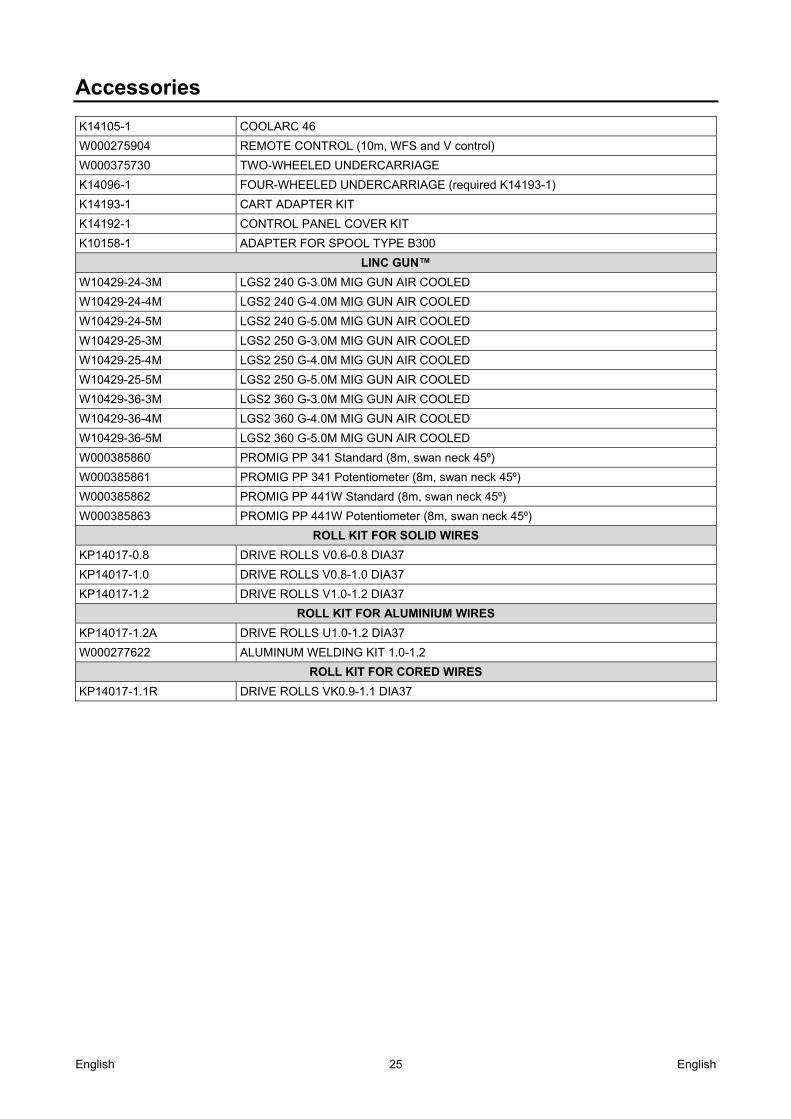
Accessories
K14105-1 COOLARC 46
W000275904 REMOTE CONTROL (10m, WFS and V control)