In the year 1875, Johnson1) revealed extraordinary changes in the toughness and breaking-strain of iron that was immersed temporarily in acid for just a few minutes. He further observed that the change is not permanent since “with the lapse of time, the metal slowly regains it original toughness and strength”. Indeed, he went on to observe that the moistened fracture surface of an embrittled steel liber-ated gas bubbles (“frothing”, with the bubbles even seen under oil). The same paper found that a strong steel has a greater loss in toughness due to immersion in acid than one which is soft. A number of acids were studied and only those that produce hydrogen by their action on iron were found to lead to a deterioration of properties. Furthermore, the hydrogen had to be nascent, not molecular, since leav-ing it in hydrogen gas did nothing to the properties of the steel. To separate out the effect of acid and hydrogen, he designed an electrochemical charging method using only Manchester town’s water, and proved that the iron electrode where hydrogen is liberated embrittled whereas the other one was not.
The paper by Johnson is a wonderful example of proper scientific method, which with elegantly simple experiments captured the essence of the embrittlement phenomenon, many aspects of which are rediscovered with much fanfare in modern literature. The following conclusions can justifi-ably be reached from this 1875 paper:
1. it is hydrogen that embrittles steel, not the acid;2. that the hydrogen is nascent, not molecular;3. it is diffusible hydrogen that embrittles1, so the phe-
nomenon is reversible;4. the effusion of diffusible hydrogen from the steel
leads to frothing (bubbles);5. that stronger steel is more susceptible to embrittle-
Prevention of Hydrogen Embrittlement in Steels
Harshad Kumar Dharamshi Hansraj BHADESHIA*
Materials Science and Metallurgy, University of Cambridge, Cambridge CB3 0FS, UK.
(Received on July 19, 2015; accepted on September 11, 2015)
The essential facts about the nature of the hydrogen embrittlement of steels have now been known for 140 years. It is diffusible hydrogen that is harmful to the toughness of iron. It follows, therefore, that the harmful influence of diffusible hydrogen can be mitigated by preventing its entry into steel or by rendering it immobile once it penetrates the material. This review deals with the methods that might be imple-mented to design steels and components that resist hydrogen embrittlement by reducing the intake of hydrogen or rendering it innocuous when it does penetrate the steel.
ment than softer versions.The role of nascent hydrogen became well-established in
the fifty years that followed, and unique experiments were published to relate the embrittlement to microstructure. For example, Pfeil6) showed that large-grained samples are more sensitive to hydrogen than those with fine structures. He postulated that hydrogen decreases the cohesion across cubic cleavage planes, but does not affect slip. Single crys-tals of iron were shown to be embrittled by hydrogen, an effect attributed to machining strains. The details of Pfeil’s and other contemporary work regarding cohesion or slip might be challenged in the light of modern understanding, but the 38 000 papers published subsequently on hydrogen embrittlement do not change the conclusions summarised above. One important phenomenon that emerged from dif-fusion measurements, is that diffusible hydrogen can be trapped at sites such as boundaries2.7) That which is likely to be sufficiently strongly trapped may not harm the steel. It follows that to produce steels that are resistant to hydro-gen, all that is necessary is to control diffusible hydrogen. This can be done by introducing benign traps in the steel or preventing the ingress of hydrogen. What follows below is based on this simple logic. We begin by considering methods that hinder the penetration of hydrogen into steels. Some of the coatings involved have multiple purposes, for example, aesthetic appearance, retention of lubricant, etc. but at the same time are significant barriers to hydrogen ingress.
1The fact that diffusible hydrogen embrittles is now widely recognised and forms the basis of many designs where the transport of hydrogen through the steel is impeded by introducing traps.2–5, e.g.) Hydrogen is present in min-ute quantities in steel, usually less than 1 part per million, but is attracted towards stress fields of the type associated with a crack tip. It therefore dif-fuses there, concentrates and thereby alters the fracture mechanism to the detriment of steel. Hence the need for diffusible hydrogen for embrittle-ment.2Pressouyre has suggested that even those features that repel hydrogen should hinder its progress through the lattice.8)
The so-called black oxide conversion-coating is generated on steel by immersion in an aqueous solution of 60–80% sodium hydroxide containing an oxidising agent such as 15–40% sodium or potassium nitrite or nitrate at a tem-perature of about 130–150°C, for ≈ 30 mins.9–11) The final oxide is magnetite,12) resulting from the following reaction sequence:9)
Fe H O Fe OH H
Fe OH OH Fe OH
Fe OH OH FeO
22 2
2 3
3 2
2 2+ +
−
− −
+ +
+
+ +
( )
( ) ( )
( ) 22
2
2
22 3 4
H O
Fe FeO Fe O+ −+ →
............. (1)
The oxide can also be a mixture of Fe3O4 and Fe2O3. The alkaline nature of the solution is important because there is no hydrogen evolved in the process (Eq. (1)) which might otherwise embrittle the steel.13) The original goal of the black oxide coating was to provide some resistance to atmospheric corrosion and this function can be enhanced by immersion of the component in hot oil because the thin oxide film, typically 1–3 μm, can otherwise be permeable3. The coating does not compromise the friction coefficient and hence can be used for components such as bearings, although the benefits are not sustained under severe operat-ing conditions.14,15) In many cases, black oxide coatings are introduced to enhance the aesthetic appearance of the product.16)
Black oxide has been applied to wind turbine bearings in an attempt to reduce the occurrence of axial cracks.17) One interpretation is that the oxide retards the diffusion of hydrogen into the steel. Permeation4 experiments on pure iron on which a passive oxide film was produced using an equivolume mixture of 0.15N Na2B4O7 ·10H2O and 0.15N NH3BO3 on the anodic side of a Devanathan and Stachurski cell, indicated a much lower influx of hydrogen into iron that is coated.18) The film studied was only 2–3 nm thick, some three orders of magnitude thinner than the black oxide coatings discussed here. Such a thin film is unlikely to be representative in the context of the porosity that is known to exist in black oxide coatings. The detailed composition of the film was not stated in the original study. Neverthe-less, the indications are that the diffusivity of hydrogen (DH) in the thin oxide film is some twelve orders of magnitude slower than in the pure, annealed iron.18) There are no similar data for the thick black oxide films. However, when steel samples are stressed using a C-ring,19) it is claimed that those that are black-oxide coated and immersed in a corro-sive solution fail later than uncoated controls; the evidence presented in support of this claim11) is at best regarded as schematic5. Nevertheless, there is a general impression in the industry that oxides of metals including steel, reduce the permeability of hydrogen and its isotopes by at least an order of magnitude.20–22)
There may be additional factors that determine the utility of such oxide coatings. The coating may, for example, help reduce surface degrading reactions between additives in the lubricant and the steel surface, thus mitigating the initiation of surface cracks.11,23,24) Surface distress has under test con-ditions been reduced in black-oxide coated samples.11) And the tendency for micropitting is reduced by the presence of black oxide during rolling-sliding wear tests, when com-pared to untreated steel.25) In summary, the oxide coating may have multiple advantages, including a reduction in the infusion of nascent hydrogen into the steel and in retarding the initiation of surface cracks caused by reactions with lubricants.
3. Cadmium, Nickel and Alloy Plating
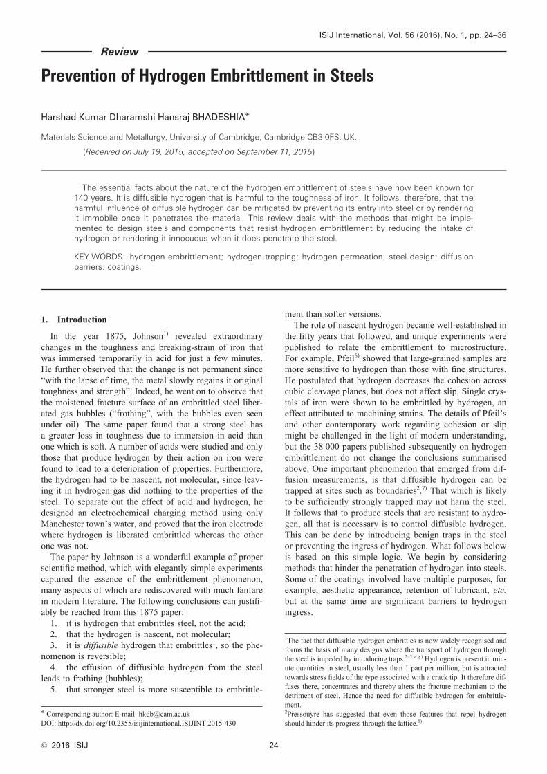
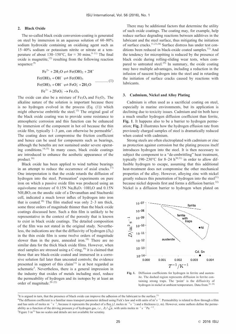
Cadmium is often used as a sacrificial coating on steel, especially in marine environments, but its application is declining due to toxicity issues. Cadmium and tin both have a much smaller hydrogen diffusion coefficient than ferrite, Fig. 1. It happens also to be a barrier to hydrogen perme-ation; Fig. 2 illustrates how the hydrogen effusion rate from previously charged samples of steel is dramatically reduced when coated with cadmium.
Strong steels are often electroplated with cadmium or zinc as protection against corrosion but the plating process itself introduces hydrogen into the steel. It is then necessary to subject the component to a “de-embrittling” heat treatment, typically 190–230°C for 8–24 h30,31) in order to allow dif-fusible hydrogen to escape, assuming that this additional heat-treatment does not compromise the other mechanical properties of the alloy. However, alloying zinc with nickel greatly reduces this penetration of hydrogen into the steel31) because nickel deposits first and forms a diffusion barrier.32) Nickel is a diffusion barrier to hydrogen when plated on
Fig. 1. Diffusion coefficients for hydrogen in ferrite and austen-ite. The dashed region represents diffusion in ferrite con-taining strong traps. The ‘point’ is the diffusivity of hydrogen in nickel at ambient temperature. Data from.26–28)
3It is argued in turn, that the presence of black oxide can improve the adhesion of the lubricant to the surface.11)
4The diffusion coefficient is a familiar mass transport parameter defined using Fick’s law and with units of m2 s −1. Permeability is related to flow through a film and has units of moles m −1 s −1, because it represents the product of a flux (J, moles m −2 s −1) and a thickness (z, m). However, some authors define the perme-ability as a function of the driving pressure p of hydrogen gas, i.e., Jz p/ , with units moles m −1 s −1 Pa −1/2 .5Figure 3 in11) has no scales and details are not available for scrutiny.
steel; the diffusivity of hydrogen in nickel at room tem-perature is about 5 × 10 −11 m2 s −1.27) Figure 1 shows that at ambient temperature, the diffusivity in nickel is orders of magnitude smaller than in ferrite, but comparable to that in ferrite containing strong hydrogen-traps. Nickel can there-fore be applied in order to prevent the infusion of hydrogen into the steel; the plating obviously should be implemented in a manner that does not introduce hydrogen into the steel.
Some illustrative data are presented in Table 1; in con-trast to 4 340 steel, the work on the 300 M alloy shows only a modest improvement due to the Zn–Ni coating relative to a cadmium coating. Figueroa and Robinson33) attribute this to the presence of defects in the Zn–Ni coating that leave some of the steel exposed, but why this is specific to 300 M steel is not clear. It is speculated that the high silicon content of 300 M relative to 4 340 may result in relatively poor surface quality for coating purposes.34–37)
It is noteworthy that the passage of hydrogen through a coating depends not only on its diffusivity, but also the ability of adsorbed hydrogen to recombine into molecular form and escape as bubbles before it is able to enter the coating. Hydrogen ingress can be reduced by the presence of cadmium in the coating because it increases this recom-
bination rate.38)
4. Other Coatings
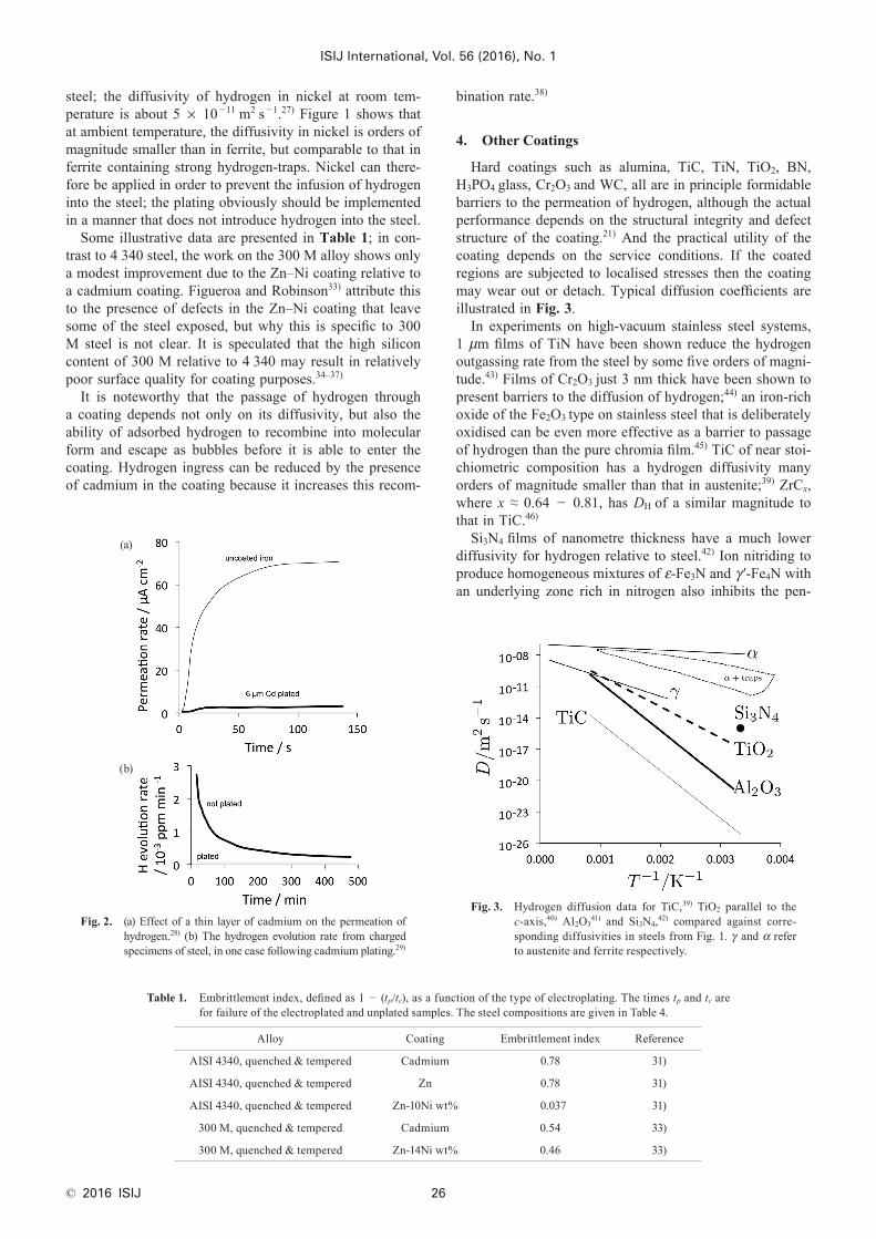
Hard coatings such as alumina, TiC, TiN, TiO2, BN, H3PO4 glass, Cr2O3 and WC, all are in principle formidable barriers to the permeation of hydrogen, although the actual performance depends on the structural integrity and defect structure of the coating.21) And the practical utility of the coating depends on the service conditions. If the coated regions are subjected to localised stresses then the coating may wear out or detach. Typical diffusion coefficients are illustrated in Fig. 3.
In experiments on high-vacuum stainless steel systems, 1 μm films of TiN have been shown reduce the hydrogen outgassing rate from the steel by some five orders of magni-tude.43) Films of Cr2O3 just 3 nm thick have been shown to present barriers to the diffusion of hydrogen;44) an iron-rich oxide of the Fe2O3 type on stainless steel that is deliberately oxidised can be even more effective as a barrier to passage of hydrogen than the pure chromia film.45) TiC of near stoi-chiometric composition has a hydrogen diffusivity many orders of magnitude smaller than that in austenite;39) ZrCx, where x ≈ 0.64 − 0.81, has DH of a similar magnitude to that in TiC.46)
Si3N4 films of nanometre thickness have a much lower diffusivity for hydrogen relative to steel.42) Ion nitriding to produce homogeneous mixtures of ε-Fe3N and γ ′-Fe4N with an underlying zone rich in nitrogen also inhibits the pen-
Table 1. Embrittlement index, defined as 1 − (tp/tc), as a function of the type of electroplating. The times tp and tc are for failure of the electroplated and unplated samples. The steel compositions are given in Table 4.
Fig. 3. Hydrogen diffusion data for TiC,39) TiO2 parallel to the c-axis,40) Al2O3
41) and Si3N4,42) compared against corre-sponding diffusivities in steels from Fig. 1. γ and α refer to austenite and ferrite respectively.
Fig. 2. (a) Effect of a thin layer of cadmium on the permeation of hydrogen.28) (b) The hydrogen evolution rate from charged specimens of steel, in one case following cadmium plating.29)
etration of hydrogen into the steel as long as the compound layer does not have defects that leave the steel exposed.47)
Alumina is particularly interesting as a hydrogen or deuterium barrier because it can be deposited using a vari-ety of well-established techniques. A 1 μm thick layer of crystalline α-alumina deposited using a plasma technique, on a reduced-activation tempered-martensitic steel has been shown to reduce the permeation flux by a factor of 103, Fig. 4.48) The coating remained adherent during thermal cycling to temperatures as high as 800°C. Aluminising involves the creation of a surface layer that is rich in alu-minium, either in solution or present as an intermetallic compound with iron; the pack process in which the steel is heated while embedded in aluminium-rich powder can be implemented on large components. The enriched region can be oxidised at the surface to produce an alumina layer < 2 μm thick, and since the aluminised region is some millime-tres in thickness, the alumina can in principle be regenerated if necessary. It has been demonstrated that the presence of alumina reduces the permeation rate of hydrogen into the underlying steel by 3–4 orders of magnitude relative to the bare steel.49)
Phosphorus ion implantation to produce a strengthened amorphous surface layer provides a diffusion barrier,50) pos-sibly implying that it is difficult for hydrogen to penetrate a disordered structure. There is evidence that the diffusion of hydrogen through an amorphous iron-base alloy is orders of magnitude slower than in ferritic steel,51) although it should be emphasised that the comparison is not rigorous because of the solutes added to make iron amorphous.
5. Hydrogen Trapping
Given that it is diffusible hydrogen that is damaging to steel,1) any method that renders it immobile should mitigate its effects. Darken and Smith7) observed experimentally that the rate of evolution of hydrogen from a charged speci-men is slower than the rate of absorption during charging. Furthermore, a cold-rolled steel sample had a much higher saturation hydrogen content than one that is hot-rolled. It was concluded, therefore, that hydrogen can be localised at dislocations or at other “disturbances of, or departures, from the ideal lattice”. Such a non-ideal lattice would be expected to impede the diffusion of hydrogen, as illustrated
by the range of values plotted in Fig. 1. The general and physically justifiable consensus is that strong traps reduce the susceptibility of the steel to hydrogen embrittlement. The presence of traps does increase the saturation hydrogen content of the steel but this trapped hydrogen is innocuous. A recent paper on X80 pipeline steel commented that the large density of traps on the steel increases its susceptibility to hydrogen-induced cracking,52) but we do not believe this is well-founded because the comment is based on the fact that the steel with traps absorbs more hydrogen.
Since a trap provides a favourable environment for the hydrogen atom to reside in, there is a reduction in energy ∆E following its transfer from a normal to a defect site53) so that ∆E is negative. Trapping energies have been widely investigated for all kinds of defects, using experimental techniques such as thermal desorption spectroscopy or mathematical models.54–60, e.g.) The intention here is not to review or assess trapping energies, but rather to focus on how such traps might be exploited in order to mitigate hydrogen embrittlement. It is generally accepted that modifi-cation of the transport rate of hydrogen is a promising route to improving hydrogen compatibility.2)
It is worth noting here that using the concept of exploiting hydrogen traps to make steels more resistant to hydrogen embrittlement was in part stimulated by the observation of delayed fracture in strong steels that are subjected to hydrogen ingress. Delayed fracture occurs when a steel subjected to a stress that is small relative to its fracture strength measured on manufacture, undergoes spontaneous brittle failure after a period of time in service.61) This failure under static load is attributed to the presence of hydrogen. Figure 5 shows how the fracture strength decreases with time in samples that have been charged electrolytically with hydrogen. The data show that for any component loaded initially at a stress greater than 600 MPa, fracture would occur after a short period in service.61)
5.1. Reversible and Irreversible TrapsIn the present context, irreversible implies that trapped
hydrogen is not able to re-enter the lattice and contribute to diffusible hydrogen during the service conditions and during the intended service life of the steel. This defini-tion is somewhat different from specifying a particular trap
Fig. 5. Fracture stress for samples of strong steel that have been electrolytically charged with hydrogen. The steel has the chemical composition Fe-0.39C-0.76Mn-0.28Si-1.8Ni-0.75Cr-0.24Mo wt%, with a 0.2% proof strength of 1 516 MPa. Data from.61)
Fig. 4. Deuterium ‘permeabilities’ through samples of Eurofer steel in its uncoated (bare) and coated (alumina) forms. Data from.48)
energy that distinguishes reversible from irreversible traps62,
e.g.) because such a procedure fails to account for time and environment. In a thermal desorption experiment, hydrogen evolved at a low temperature is weakly trapped whereas the ‘irreversibly’ trapped hydrogen is only released at higher temperatures. However, the actual temperature at which significant quantities of hydrogen are detrapped, depends also on the heating rate, emphasising the role of time. The equilibrium between trapped hydrogen and that dissolved in the matrix means that when the latter escapes, that which is trapped will release hydrogen to re-establish equilibrium, a phenomenon confirmed directly using autoradiography.63) As pointed out by Maroef et al.,58) a trap with a binding energy of 100 kJ mol −1 is considered irreversible at ambi-ent temperature but becomes reversible at a sufficiently high temperature.
The distinction between reversible and irreversible traps becomes particularly important when modelling the effect of hydrogen on mechanical properties. The quantitative effect
is expressed as an empirical hydrogen influence factor 64–66) that then is incorporated into expressions for the fatigue crack growth rate. The influence factor is defined differently for diffusible and nondiffusible hydrogen, with a working assumption that the hydrogen released under ‘ambient con-ditions’ is classified as diffusible.67)
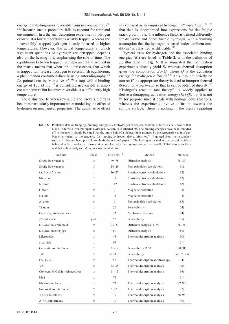
Typical traps for hydrogen and the associated binding energies (Eb) are listed in Table 2, with the definition of Eb illustrated in Fig. 6. It is suggested that permeation experiments directly yield Eb whereas thermal desorption gives the combination Eb+Q, where Q is the activation energy for hydrogen diffusion.58) This may not strictly be correct if the appropriate theory is used to interpret thermal desorption experiments so that Eb can be obtained directly.68) Kissinger’s reaction rate theory69) is widely applied to derive a detrapping activation energy (Eb+Q), but it is not fit for purpose since it deals with homogeneous reactions, whereas the experiments involve diffusion towards the sample surface. There is nothing in the theory regarding
Table 2. Published data on trapping (binding) energies Eb for hydrogen or deuterium atoms in ferritic steels. Notice that nickel in ferritic iron (α) repels hydrogen. Austenite is labelled ‘γ’. The binding energies have been rounded off to integers. It should be noted that the strain field of a dislocation is reduced by the segregation to it of car-bon or nitrogen, so the tendency for trapping hydrogen also diminishes.76) († quoted from the secondary source;2) it has not been possible to obtain the original paper.77) The hydrogen located at microscopic voids is believed to be in molecular form so it is not clear why the trapping energy is so small. ‘TDA’ stands for ther-mal desorption analysis. ‘M’ represents metal atoms.
Trap site Phase −Eb/kJ mol −1 Method Reference
Single iron-vacancy α 49–78 Diffusion analysis 78–80)
Single iron-vacancy α 24–29 First principles calculations 81)
Cr, Mo or V atom α 26–27 Elastic/electronic calculations 82)
Mn atom α 11 Elastic/electronic calculations 82)
Ni atom α −12 Elastic/electronic calculations 82)
C atom α 3 Magnetic relaxation 73)
N atom α 13 Magnetic relaxation 73)
Al atom γ 6 First principles calculation 83)
Ti atom α 26 Permeability 54)
General grain boundaries α 32 Mechanical analysis 84)
γ /α interface γ+α 52 Permeability 85)
Dislocation strain field α 23–27 Diffusion analysis, TDA 86–88)
sample shape and size. McNabb and Foster’s model,70) on the other hand, explicitly handles Q and Eb and therefore is able to deal with the capture and release of hydrogen from traps, and its diffusion through the lattice. There will, in any event, be considerable uncertainties in the measurement of Eb for all techniques since much of the theory is applied as if there is a single type of trap site, whereas in practice a real material will contain a variety of traps and a spectrum of binding energies. This kind of a problem is best handled using numerical or computational methods as in.68,71) In spite of these uncertainties in the absolute values of Eb, it is likely that the rankings of trap potencies are reasonable; for example, a dislocation core is expected to be a deeper trap for hydrogen than its elastic strain field (Table 2).
Table 2 also lists the trapping ability of individual solutes. The binding energies quoted are likely to be reliable as far as the separation of the activation energy of diffusion and Eb is concerned, because they come from calculations or magnetic relaxation methods. Furthermore, those deduced using techniques such as thermal desorption spectroscopy may not be rigorous because the solutes also cause micro-structural changes and hence trapping tendencies; this is reflected, for example, in the study of the role of tungsten on hydrogen trapping.72)
Voids into which hydrogen locates and combines to form the molecular variety would in general fall into the irrevers-ible category because the molecular hydrogen would need to dissociate before it can re-enter the iron lattice. On the other hand, although carbon atoms dissolved in the steel have an association with hydrogen,73) they represent weak traps;74) if the diffusible hydrogen in the lattice reaches a concentration below that expected in equilibrium with such a trap, then the hydrogen would be expected to re-enter solution.
Even weak traps reduce the ability of hydrogen to dif-fuse through the steel. Thus, water-quenched, martensitic 2.25Cr1Mo steel has an apparent hydrogen diffusivity at ambient temperature, as measured by permeation, to be DH = 0.21−0.31 × 10 −10 m2 s −1. After tempering at 640°C to generate a variety of carbides, the diffusivity increases to DH = 0.29−0.47×10¹⁰ m2 s −1, but the quantity of irre-versibly trapped hydrogen increases by about an order of magnitude relative to the untempered state.75)
6. Atomic Traps
We have seen from the data presented in Table 2 that indi-vidual atoms can attract hydrogen atoms but the mechanism of trapping can vary, and each solute atom is not in general likely to attract more than a couple of hydrogen atoms.
The chemical affinity of titanium for hydrogen is known to be potent. Hydride precipitation is possible in titanium based alloys and because the reaction is revers-ible, hydrides have been proposed for large scale hydrogen storage systems. Pressouyre and Bernstein54) demonstrated that titanium atoms in Fe–Ti ferritic alloys can act as low-occupation traps with −EB ≈ 26 kJ mol −1.
High-manganese twinning-induced plasticity steels (TWIP, typically Fe-18Mn-1.5Al-0.6C wt%) exhibit com-binations of elongation and strength that might be attrac-tive100–102) but can be susceptible to delayed, hydrogen-induced failure.103–108) However, it is known that adding less than 2 wt% of aluminium ameliorates the situation.60,109) Possible mechanisms of the role of aluminium include:• suppression of strain ageing due to carbon, with the
resulting reduction in the flow stress making hydrogen embrittlement less likely.110)
• Aluminium might reduce the absorption of hydro-gen111,112) but this is inconsistent with experimental data113,114) that indicate the opposite effect.• Phase transformation into ε-martensite, or mechanical
twinning, may mitigate hydrogen effects.113)
• Hydrogen reduces the shear modulus of the austenite whereas aluminium has the opposite effect in the presence of hydrogen. This might in some way relate to hydrogen embrittlement.114)
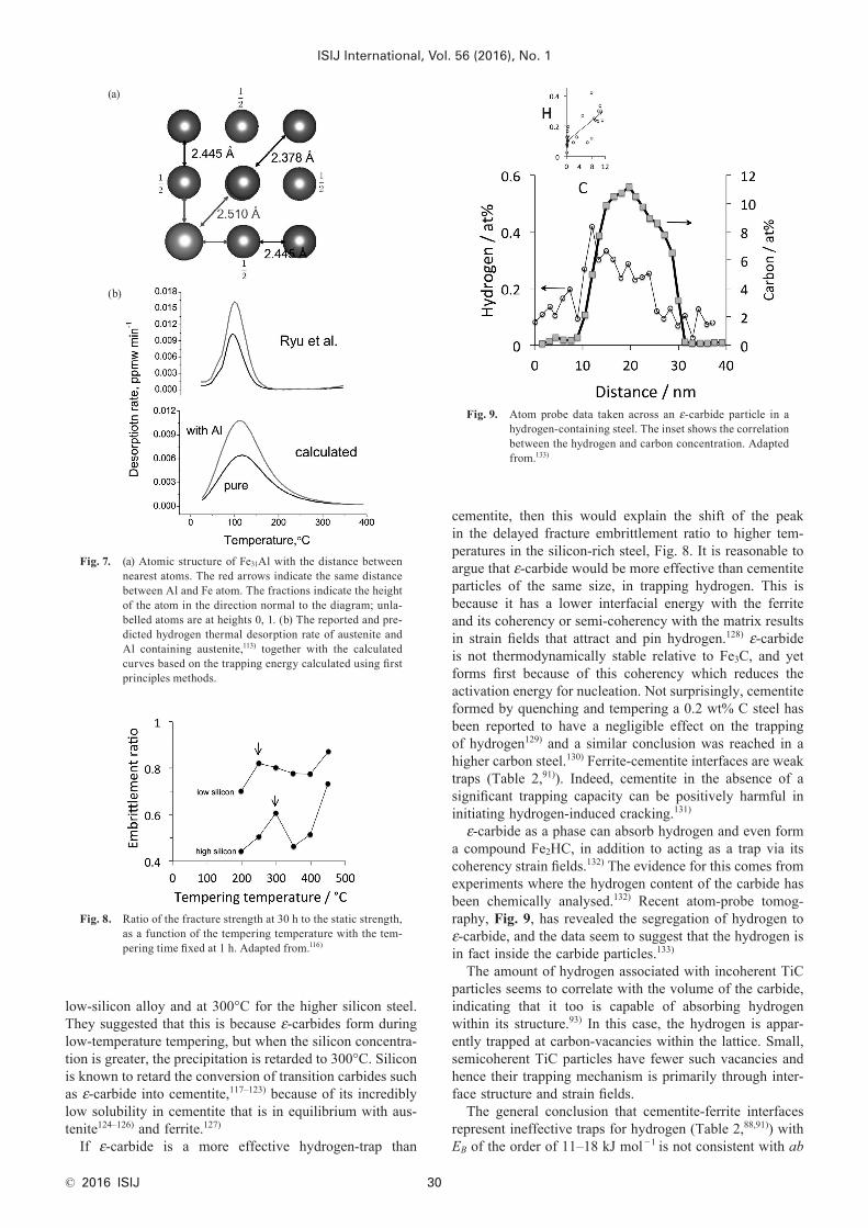
There is a further explanation that is generic to ferritic and austenitic steels, that aluminium influences binding energies and the local density around the aluminium atoms. Thus, in the context of low-alloy steels, first principles calcula-tions show that aluminium-alloyed ferrite should be more resistant to hydrogen than that which has silicon added.115) In austenite, the distance between a substituted aluminium atom and the adjacent iron atom is greater than between a corresponding pair of iron atoms (Fig. 7(a)). This additional space makes an atom of aluminium a weak trap with a binding energy of 6 kJ mol −1, which is the reason why the aluminium-alloyed TWIP steel absorbs more hydrogen in charging experiments (Fig. 7(b)).
7. ε-carbide and Cementite
Fukui et al.116) studied the delayed fracture behaviour of six different steels following immersion in a 0.1N HCl solution for 30 h. They characterised the response with the ratio of the fracture strength measured following immersion, to the strength determined in the unexposed samples. The steels were quenched and then tempered at a variety of tem-peratures, in all cases for 1 h. Two of the steels studied had similar carbon concentrations in the range 0.2–0.21 wt%, but quite different silicon contents at 0.27 and 0.75 wt%. It was noted that both steels exhibited favourable peaks in the embrittlement ratio6, with the peak at 250°C (Fig. 8) in the
6This ratio is sometimes known as the ‘delayed fracture ratio’.
Fig. 6. Illustration of the binding energy, and activation energy of diffusion in the perfect lattice.
low-silicon alloy and at 300°C for the higher silicon steel. They suggested that this is because ε-carbides form during low-temperature tempering, but when the silicon concentra-tion is greater, the precipitation is retarded to 300°C. Silicon is known to retard the conversion of transition carbides such as ε-carbide into cementite,117–123) because of its incredibly low solubility in cementite that is in equilibrium with aus-tenite124–126) and ferrite.127)
If ε-carbide is a more effective hydrogen-trap than
cementite, then this would explain the shift of the peak in the delayed fracture embrittlement ratio to higher tem-peratures in the silicon-rich steel, Fig. 8. It is reasonable to argue that ε-carbide would be more effective than cementite particles of the same size, in trapping hydrogen. This is because it has a lower interfacial energy with the ferrite and its coherency or semi-coherency with the matrix results in strain fields that attract and pin hydrogen.128) ε-carbide is not thermodynamically stable relative to Fe3C, and yet forms first because of this coherency which reduces the activation energy for nucleation. Not surprisingly, cementite formed by quenching and tempering a 0.2 wt% C steel has been reported to have a negligible effect on the trapping of hydrogen129) and a similar conclusion was reached in a higher carbon steel.130) Ferrite-cementite interfaces are weak traps (Table 2,91)). Indeed, cementite in the absence of a significant trapping capacity can be positively harmful in initiating hydrogen-induced cracking.131)
ε-carbide as a phase can absorb hydrogen and even form a compound Fe2HC, in addition to acting as a trap via its coherency strain fields.132) The evidence for this comes from experiments where the hydrogen content of the carbide has been chemically analysed.132) Recent atom-probe tomog-raphy, Fig. 9, has revealed the segregation of hydrogen to ε-carbide, and the data seem to suggest that the hydrogen is in fact inside the carbide particles.133)
The amount of hydrogen associated with incoherent TiC particles seems to correlate with the volume of the carbide, indicating that it too is capable of absorbing hydrogen within its structure.93) In this case, the hydrogen is appar-ently trapped at carbon-vacancies within the lattice. Small, semicoherent TiC particles have fewer such vacancies and hence their trapping mechanism is primarily through inter-face structure and strain fields.
The general conclusion that cementite-ferrite interfaces represent ineffective traps for hydrogen (Table 2,88,91)) with EB of the order of 11–18 kJ mol −1 is not consistent with ab
Fig. 8. Ratio of the fracture strength at 30 h to the static strength, as a function of the tempering temperature with the tem-pering time fixed at 1 h. Adapted from.116)
Fig. 9. Atom probe data taken across an ε-carbide particle in a hydrogen-containing steel. The inset shows the correlation between the hydrogen and carbon concentration. Adapted from.133)
Fig. 7. (a) Atomic structure of Fe31Al with the distance between nearest atoms. The red arrows indicate the same distance between Al and Fe atom. The fractions indicate the height of the atom in the direction normal to the diagram; unla-belled atoms are at heights 0, 1. (b) The reported and pre-dicted hydrogen thermal desorption rate of austenite and Al containing austenite,113) together with the calculated curves based on the trapping energy calculated using first principles methods.
initio calculations that suggest EB ≈ 47 kJ mol −1.134) How-ever, the calculations may not be representative because the interface studied had to be made coherent due to the nature of the method used, by artificially implementing a huge adjustment to particular lattice parameters.
8. Substitutionally-Alloyed Carbides and Nitrides
The carbide particles that precipitate at temperatures where substitutional solutes such as molybdenum, vana-dium, niobium and titanium become mobile over length scales of a few nanometres are particularly interesting from the point of view of hydrogen trapping. With appropriate tempering at temperatures in the range 500–600°C, the distance over which the atoms will move is in the range 1–1 000 nm135, p. 74) for typical tempering times. This means that the carbide dispersion can be carefully controlled while at the same time selecting tempering conditions that are suit-able for the other properties required of the steel.136)
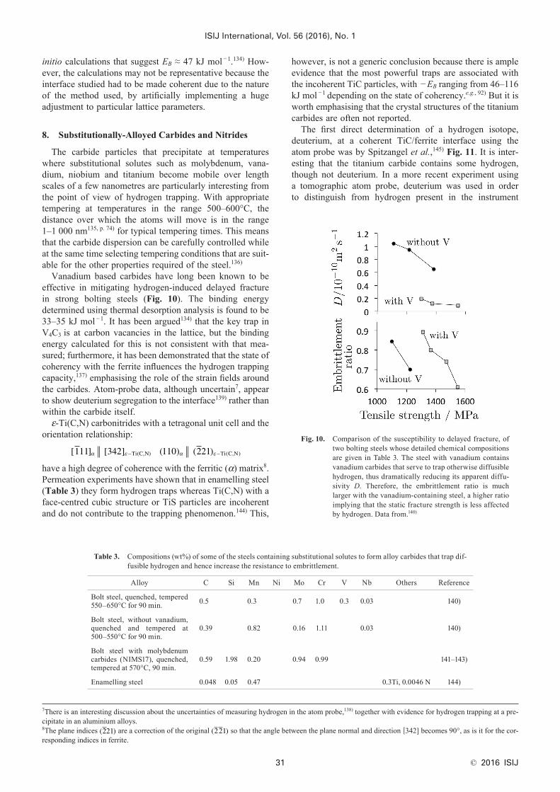
Vanadium based carbides have long been known to be effective in mitigating hydrogen-induced delayed fracture in strong bolting steels (Fig. 10). The binding energy determined using thermal desorption analysis is found to be 33–35 kJ mol −1. It has been argued134) that the key trap in V4C3 is at carbon vacancies in the lattice, but the binding energy calculated for this is not consistent with that mea-sured; furthermore, it has been demonstrated that the state of coherency with the ferrite influences the hydrogen trapping capacity,137) emphasising the role of the strain fields around the carbides. Atom-probe data, although uncertain7, appear to show deuterium segregation to the interface139) rather than within the carbide itself.ε-Ti(C,N) carbonitrides with a tetragonal unit cell and the
orientation relationship:
[ ] [ ] ( ) ( )(C,N) ( , )111 342 110 221α ε α ε− −Ti Ti C N
have a high degree of coherence with the ferritic (α) matrix8. Permeation experiments have shown that in enamelling steel (Table 3) they form hydrogen traps whereas Ti(C,N) with a face-centred cubic structure or TiS particles are incoherent and do not contribute to the trapping phenomenon.144) This,
however, is not a generic conclusion because there is ample evidence that the most powerful traps are associated with the incoherent TiC particles, with − EB ranging from 46–116 kJ mol −1 depending on the state of coherency.e.g., 92) But it is worth emphasising that the crystal structures of the titanium carbides are often not reported.
The first direct determination of a hydrogen isotope, deuterium, at a coherent TiC/ferrite interface using the atom probe was by Spitzangel et al.,145) Fig. 11. It is inter-esting that the titanium carbide contains some hydrogen, though not deuterium. In a more recent experiment using a tomographic atom probe, deuterium was used in order to distinguish from hydrogen present in the instrument
Fig. 10. Comparison of the susceptibility to delayed fracture, of two bolting steels whose detailed chemical compositions are given in Table 3. The steel with vanadium contains vanadium carbides that serve to trap otherwise diffusible hydrogen, thus dramatically reducing its apparent diffu-sivity D. Therefore, the embrittlement ratio is much larger with the vanadium-containing steel, a higher ratio implying that the static fracture strength is less affected by hydrogen. Data from.140)
7There is an interesting discussion about the uncertainties of measuring hydrogen in the atom probe,138) together with evidence for hydrogen trapping at a pre-cipitate in an aluminium alloys.8The plane indices ( )221 are a correction of the original ( )221 so that the angle between the plane normal and direction [342] becomes 90°, as is it for the cor-responding indices in ferrite.
Table 3. Compositions (wt%) of some of the steels containing substitutional solutes to form alloy carbides that trap dif-fusible hydrogen and hence increase the resistance to embrittlement.
Alloy C Si Mn Ni Mo Cr V Nb Others Reference
Bolt steel, quenched, tempered 550–650°C for 90 min. 0.5 0.3 0.7 1.0 0.3 0.03 140)
Bolt steel, without vanadium, quenched and tempered at 500–550°C for 90 min.
0.39 0.82 0.16 1.11 0.03 140)
Bolt steel with molybdenum carbides (NIMS17), quenched, tempered at 570°C, 90 min.
0.59 1.98 0.20 0.94 0.99 141–143)
Enamelling steel 0.048 0.05 0.47 0.3Ti, 0.0046 N 144)
itself;146) this work confirmed the segregation of deuterium in the proximity of the small titanium carbides. Spitzangel et al. suggested that it would be useful to examine larger, incoherent particles, to see whether the particles themselves contained hydrogen.
Atom probe tomography has been reported for deuterium segregation in the proximity of V4C3 precipitates.139) Simi-lar results have been reported for ε-carbide because there is a strong correlation between the carbon and hydrogen concentrations.133) Figure 12 shows two examples of experi-ments that demonstrate that carefully designed vanadium-molybdenum carbide can be very effective in trapping hydrogen. In the case of the bearing steel SUJ2,147,148) the sample was tested immediately after charging and it was established using a control experiment where the sample was heated at 3K min −1, that the peak below about 150°C is due to the evolution of diffusible hydrogen. Data con-firming the attribution of this peak to diffusible hydrogen are available also for lower carbon quenched and tempered steels149) and for pure iron and eutectoid steels.150) The actual temperature range over which diffusible hydrogen
is released will depend on the heating rate and sample size used in thermal desorption analysis9. The subsequent smaller peak at temperatures in excess of 350°C corresponds to the release of trapped hydrogen, although the nature of the traps was not stated.
The second steel is not a bearing alloy, and is tested after allowing the diffusible hydrogen to escape from the 8 mm diameter samples by holding at 20°C for 100 h.137) It is heat treated to precipitate fine particles of (V,Mo)4C3
which through their coherency strain fields are able to trap hydrogen. The peak corresponding to this particular alloy therefore represents only the trapped hydrogen.
8.1. Efficacy of TrapsWhile traps undoubtedly reduce the mobility of hydrogen
atoms in ferrite or austenite, in circumstances where the amount of hydrogen that enters the steel is large, they actu-ally increase the uptake of hydrogen. Given that the trapped hydrogen will be in local equilibrium with the lattice, if EB is small, then it would be easy for the trap to act as a source of diffusible hydrogen if the concentration in the matrix becomes depleted below the equilibrium value. The traps in these cases would not mitigate the embrittlement of the steel. Akiyama143) pointed out that a particular bolting steel (Table 3) containing molybdenum carbides did not show exceptional resistance to hydrogen embrittlement in cyclic corrosion tests because of the high hydrogen uptake of the steel.141) The molybdenum carbides are relatively weak traps (Table 2) and hence the supply of diffusible hydrogen would be maintained by equilibrium with the matrix. In order for traps to be effective, they must have a large enough binding energy so that the equilibrium concentration of diffusible hydrogen in the matrix is much smaller than required to cause embrittlement.
It has been suggested that there is a critical diffusible-hydrogen concentration HC below which delayed fracture does not occur for a steel with the microstructure defined. This is determined experimentally. If the amount of hydro-gen that enters the steel from the environment, HE, is less than HC, then delayed fracture is said not to occur in ser-vice.29,152,153) So the problem reduces to one in which the steel and its heat treatment are designed to maximise HC, possibly by using hydrogen trapping carbides. In the work described in the preceding paragraph,143) laboratory experi-ments were performed in which samples were charged with hydrogen, rather than exposed to an environment. There-fore, the traps would have been saturated, and subsequently served as sources for hydrogen. What really is needed in order to assess the efficacy of traps is a reliable measure of HE and this presumably cannot be achieved without exposure in an actual service environment. Tarui et al.153) claim that there is little correlation between accelerated tests (using hydrogen charging) and performance in actual environments. Figure 13 is a particularly useful extract from more comprehensive data,154) because the bolt did not contain diffusible hydrogen, only trapped hydrogen and in a quantity that turned out to be very small, at about 0.2 p.p.m. This is important to note because numbers like these define the trap capacity that must be built into bolts in order to
9A useful practical definition of diffusible hydrogen is that which escapes when the steel is left at room temperature for several days.151)
Fig. 12. Hydrogen evolution rates. Both alloys were cathodically charged with hydrogen at 0.2 mA cm −2. (a) A standard bearing steel,148, Table 1) charged for 20 h and then immedi-ately tested for hydrogen evolution.147) (b) An alloy containing coherent (V,Mo)4C3 hydrogen–trapping pre-cipitates, charged for 48 h, and tested after allowing dif-fusible hydrogen to escape.137)
Fig. 11. The horizontal lines represent the sequence of ions enter-ing the time of flight mass spectrometer of an atom probe, with the probe hole placed at the TiC/ferrite inter-face. Only the deuterium and hydrogen ions are plotted, the Fe, C, Ti omitted for clarity. No deuterium atoms were detected in the sequence far from the interface. The far field is not illustrated here but is available in 145) from which this figure is adapted.
avoid delayed fracture.Although some inclusions such as MnS are associated
with large trapping energies (Table 2), the inclusions them-selves can harm the overall properties depending on their size and distribution. It has, for example, been concluded that the experimentally observed accumulation of hydrogen around MnS inclusions is responsible for failure in fatigue testing.155) This applies also to fatigue initiated at oxide inclusions.156,157) Therefore, inclusions that are weakly bonded to the steel and at the same time initiate fracture because of their size, are not suitable as deliberate hydrogen traps. As emphasised in the introduction, it is the benign traps such as the semi-coherent carbides that should be exploited in this context.
9. Retained Austenite and Hydrogen Mobility
In a study of two quenched and tempered martensitic steels, Figueroa and Robinson33) concluded that martensite which is surrounded by retained austenite is more resistant to hydrogen embrittlement because the austenite is a sink for hydrogen. AerMet 100 (Table 4) often contains austenite that forms by reversion during the seondary-hardening heat treatment; this correlates with the absence of significant embrittlement following electroplating. In contrast, the same treatment causes a large loss of toughness at comparable strength, in 300 M steel which does not contain austenite in its microstructure.
Retained austenite is able to act as a trap for three rea-sons, first that the solubility of hydrogen is greater in that phase, secondly the low rate at which hydrogen can diffuse in austenite, and thirdly, the γ /α interface is a strong trap85) so that once the hydrogen enters the austenite, it is more difficult for it to leave. The ability of retained or reverted austenite to absorb excess hydrogen has been repeatedly demonstrated.33,158–164, e.g.) It should be noted that if the austenite during service transforms into brittle martensite,
the latter would inherit the hydrogen concentration of the austenite, which is likely to be detrimental to overall prop-erties.158)
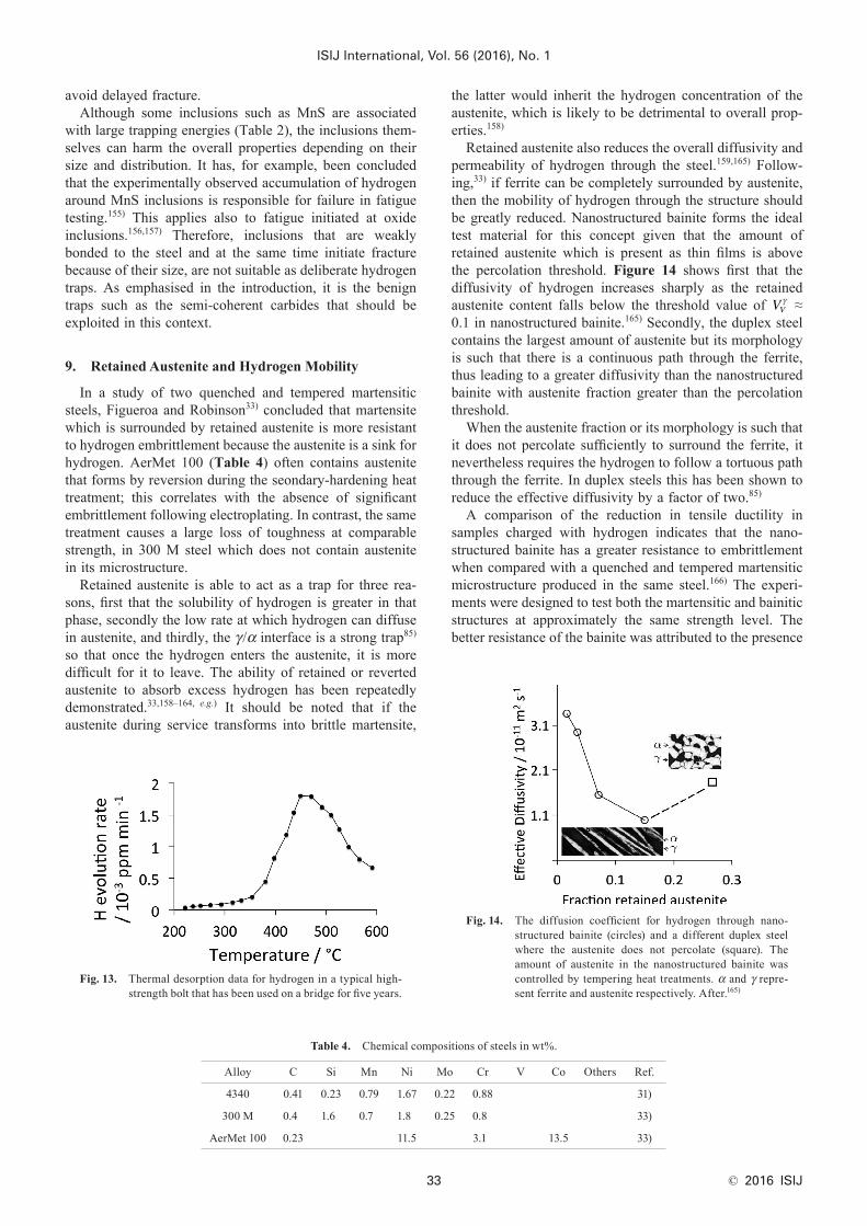
Retained austenite also reduces the overall diffusivity and permeability of hydrogen through the steel.159,165) Follow-ing,33) if ferrite can be completely surrounded by austenite, then the mobility of hydrogen through the structure should be greatly reduced. Nanostructured bainite forms the ideal test material for this concept given that the amount of retained austenite which is present as thin films is above the percolation threshold. Figure 14 shows first that the diffusivity of hydrogen increases sharply as the retained austenite content falls below the threshold value of VV
γ ≈ 0.1 in nanostructured bainite.165) Secondly, the duplex steel contains the largest amount of austenite but its morphology is such that there is a continuous path through the ferrite, thus leading to a greater diffusivity than the nanostructured bainite with austenite fraction greater than the percolation threshold.
When the austenite fraction or its morphology is such that it does not percolate sufficiently to surround the ferrite, it nevertheless requires the hydrogen to follow a tortuous path through the ferrite. In duplex steels this has been shown to reduce the effective diffusivity by a factor of two.85)
A comparison of the reduction in tensile ductility in samples charged with hydrogen indicates that the nano-structured bainite has a greater resistance to embrittlement when compared with a quenched and tempered martensitic microstructure produced in the same steel.166) The experi-ments were designed to test both the martensitic and bainitic structures at approximately the same strength level. The better resistance of the bainite was attributed to the presence
Fig. 14. The diffusion coefficient for hydrogen through nano-structured bainite (circles) and a different duplex steel where the austenite does not percolate (square). The amount of austenite in the nanostructured bainite was controlled by tempering heat treatments. α and γ repre-sent ferrite and austenite respectively. After.165)
Table 4. Chemical compositions of steels in wt%.
Alloy C Si Mn Ni Mo Cr V Co Others Ref.
4340 0.41 0.23 0.79 1.67 0.22 0.88 31)
300 M 0.4 1.6 0.7 1.8 0.25 0.8 33)
AerMet 100 0.23 11.5 3.1 13.5 33)
Fig. 13. Thermal desorption data for hydrogen in a typical high-strength bolt that has been used on a bridge for five years.
of retained austenite and a large density of interfaces that might trap hydrogen.
Finally, it is noteworthy that hydrogen per se does not influence the stability of the austenite.167)
10. Lath Boundaries
In a comparison of a variety of linepipe steel (0.05 wt% C) microstructures, permeation experiments established that bainite and acicular ferrite microstructures are far more effective in trapping hydrogen than ferrite-pearlite mixtures.168) The measured apparent diffusivities were reduced by a factor of two by the trapping of hydrogen at the finely dispersed cementite/lath interfaces. This led to a significant increase in the resistance to hydrogen induced cracking. In that study,168) cracks were found to nucleate at martensite-austenite boundaries (the so-called MA con-stituent). In a higher carbon steel containing three times as much carbon (0.15 wt% C), the microstructure at the lath boundaries was in addition found to be effective in trapping hydrogen, but cracks also initiated at those boundaries, pre-sumably because of the coarser cementite particles,169) and as a consequence, the tendency to crack normal to the lath boundaries.
11. Summary
That hydrogen embrittles iron, both austenitic and ferritic, is in no doubt and it does so at incredibly low average con-centrations. It has been known since 1875 that it is diffusible hydrogen that is harmful. The conventional wisdom is that diffusion is necessary so that the hydrogen can concentrate at stress concentrations such as the tips of sharp cracks and therefore has greater consequences than indicated by a low average concentration.
Figure 15 illustrates the key mechanisms that exist to ameliorate the effects of hydrogen in steel. A plethora of coatings exist that have been demonstrated to reduce either the outgassing of hydrogen in vacuum systems, or as dif-fusion barriers to the ingress of hydrogen. However, the choice of coatings available decreases when the coating has
to perform multiple functions, for example to resist abrasion and impact. Coatings will contain defects that locally expose the steel; some sort of a sacrificial mechanism is then called for as in the case of the Zn–Ni coatings. The thickness and integrity of the coating will vary with the manufacturing process and has to be compatible with the service conditions of the protected component. The quality of the coating can depend on the chemical composition and structure of the substrate. Ion implantation can be used to favourably alter the surface of the steel.
Some phases within steels can actually soak-up hydro-gen, for example the ε-carbide; however, retained austenite which is common in steels may be the most promiscuous hydrogen sink. In TRIP steels the austenite usually contains a large carbon concentration and is designed to transform into martensite under the influence of stress or plastic strain. The martensite would then inherit the hydrogen con-centration present originally in the austenite and this may compromise the overall properties. Reverted austenite in marageing steels or in secondary-hardened steels containing a stoichiometric concentration of carbon are not expected to suffer from this difficulty because of the zero or low carbon concentration of the alloys.
Retained austenite can have a different function, that of acting as a diffusion barrier to hydrogen in predominantly ferritic steels. However, its volume fraction must be above a percolation threshold so that the ferrite is microscopically isolated. Even when the fraction is below the percolation threshold, the austenite can increase the tortuousity of the path that the hydrogen must follow through the structure, and hence reduce its ingress.
There are many varieties of strong hydrogen traps in steels, but by far the most advanced application of the con-cept of capturing diffuisible hydrogen within the steel has been in the invention of strong bolting steels that are not susceptible to delayed fracture. The bolts have been tested for many years in service and demonstrated to outperform those that do not contain the hydrogen traps. Furthermore, even after years of service, the bolts in their operating environment were found to contain less than 1 p.p.m. of hydrogen. The actual trapping capacity from the vanadium carbides is in fact much greater that that.
REFERENCES
1) W. H. Johnson: Proc. Royal Soc. Lon., 23 (1875), 168.2) E. Serra, A. Perujo and G. Benamati: J. Nucl. Mater., 245 (1997), 108.3) M. Wang, E. Akiyama and K. Tsuzaki: Corros. Sci., 49 (2007),
4081.4) G. T. Park, S. U. Koh, H. G. Jung and K. Y. Kim: Corros. Sci., 50
(2008), 1865.5) Y. D. Han, H. Y. Jing and L. Y. Xu: Mater. Chem. Phys., 132
(2012), 216.6) L. P. Pfeil: Proc. Royal Soc. Lond., 112 (1926), 182.7) L. S. Darken and R. P. Smith: Corrosion, 5 (1949), 1.8) G. M. Pressouyre: Metall. Mater. Trans. A, 14 (1983), 2189.9) R. M. Hurd and N. Hackerman: J.Electrochem. Soc., 104 (1957),
482.10) L. H. Wagner: Corrosion Resistance of Black Oxide Coatings on
Mild andCorrosion Resistant Steel, Tech. Rep. 64-3580, Rock Island Arsenal Laboratory, IL, (1964).
11) K. Stadler, B. Han, V. Brizmer and R. Pasaribu: Technology Evolu-tion, (2015), No. 2, 25.
12) K. Nomura: Mössbauer Spectroscopy in Materials Science, Ch. 4, Springer, Netherlands, (1999), 63.
13) R. H. Wolff: Hydrogen Embrittlement of Steel in Metal Finishing Processes of Black Oxide and Zinc Phosphate, Tech. Rep. 66-2008, Rock Island Arsenal Laboratory, IL, (1966).
Fig. 15. Mechanisms available for the modification of steel to bet-ter resist hydrogen.
14) R. D. Evans, C. H. Hager and R. D. Logsdon: Int. Joint Tribology Conf., IJTC2009-15206, ASME, New York, (2009), 1.
15) R. D. Evans, C. H. Hager Jr., Y. S. Kang and G. L. Doll: Tribology Trans., 58 (2015), 444.
16) A. A. bin Ahmad Fauzi: Master’s thesis, Universitat Politècnica de Catalunya: Barcelona, Spain, (2014).
17) R. Errichello, S. Sheng, J. Keller and A. Greco: Wind turbine Tri-bology Seminar, Tech. Rep. DOE/GO-102012-3496 Feb. 2012, U. S. Department of Energy: Golden, CO, (2012).
18) R. H. Song, S. I. Pyung and R. A. Oriani: Electrochim. Acta, 36 (1991), 825.
19) B. Han, B. X. Zhou and R. Pasaribu: Proc. Eur. Corrosion Cong., European Federation of Corrosion, Frankfurt, (2011), 615.
20) D. Khatamian and F. D. Manchester: J. Nucl. Mater., 166 (1989), 300.
21) G. W. Hollenberg, E. P. Simonen, G. Kalinin and A. Terlain: Fusion Eng. Design, 28 (1995), 190.
22) E. Serra and G. Benamati: Mater. Sci. Technol., 14 (1998), 573.23) M. Reichelt, T. E. Weirich, J. Meyer, T. Wolf, J. Loos, P. W. Gold
and M. Fajfrowski: J. Mater. Sci., 41 (2006), 4543.24) H. R. Pasaribu and P. M. Lugt: Tribology Trans., 55 (2012), 351.25) B. Mahmoudi, B. Tury, C. H. Hager and G. L. Doll: Tribol. Lett.,
58 (2015), 1.26) F. R. Coe: Welding Steels without Hydrogen Cracking: Tech. Rep.,
The Welding Institute: Abingdon, U. K. (1973).27) M. L. Hill and E. W. Johnson: Acta Metall., 3 (1955), 566.28) M. Zamanzadeh, A. Allam, C. Kato, B. Ateya and H. W. Pickering:
J. Electrochem. Soc., 129 (1982), 284.29) S. Yamasaki and T. Takahashi: Tetsu-to-Hagané, 83 (1997), 454.30) M. P. Nascimento, R. C. Souza, W. L. Pigatin and H. J. C.
Voorwald: Int. J. Fatigue, 23 (2001), 607.31) E. M. K. Hillier and M. J. Robinson: Corros. Sci., 48 (2004), 715.32) M. J. Carr and M. J. Robinson: Trans. IMF, 73 (1995), 58.33) D. Figueroa and M. J. Robinson: Corros. Sci., 50 (2006), 1066.34) T. Fukagawa, H. Okada and Y. Maehara: ISIJ Int., 34 (1994), 906.35) H. Okada, T. Dukagawa, A. Okamoto, M. Azuma and Y. Matsuda:
ISIJ Int., 35 (1995), 886.36) S. Taniguchi, K. Yamamoto, D. Megumi and T. Shibata: Mater. Sci.
Eng. A, 308 (2001), 250.37) E. J. Song, D. W. Suh and H. K. D. H. Bhadeshia: Ironmaking
Steelmaking, 39 (2012), 599.38) H. Kim, B. N. Popov and K. S. Chen: Corros. Sci., 45 (2003), 1505.39) Y. Hatano, T. Nozaki, H. Homma and M. Matsuyama: Annual
Report of Hydrogen Isotope Research Center, Vol. 26, Toyama University, Japan, (2006), 31.
40) J. B. Bates, J. C. Wang and R. A. Perkins: Phys. Rev. B, 19 (1979), 4130.
41) A. B. Belonoshko, A. Rosengren, Q. Dong, G. Hultquist and C. Leygraf: Phys. Rev. B, 69 (2004), 024302.
42) G. C. Yu and S. K. Yen: Appl. Surf. Sci., 201 (2002), 204.43) K. Saito, Y. Inayoshi, Y. Ikeda, Y. Yang and S. Tsukahara: J. Vac.
Sci. Technol., 13 (1995), 556.44) M. Takeda, H. Kurisu, S. Yamamoto and H. Nakagama: Vacuum,
84 (2010), 352.45) Y. Ishikawa and T. Yoshimura: J. Vac. Sci. Technol., 13 (1995),
1847.46) Y. Hatano, T. Nozaki, H. Homma and M. Matsuyama: Annual
Report of Hydrogen Isotope Research Center, Vol. 27, Toyama University, Japan, (2007), 27.
47) P. Bruzzoni, S. P. Brühl, B. A. Gómez, L. Nosei, M. Ortiz and J. N. Feugeas: Surf Interface Anal., 110 (1998), 13.
48) D. Levchuk, F. Koch, H. Maier and H. Bolt: J. Nucl. Mater., 328 (2004), 103.
49) K. S. Forcey, D. K. Ross and C. H. Wu: J. Nucl. Mater., 182 (1991), 36.
50) W. Ensinger and G. K. Wolf: Nucl. Instrum. Meth. B, 39 (1989), 552.
51) D. S. Dos Santos and P. V. De Miranda: J. Mater. Sci., 32 (1997), 6311.
52) J. Dong, H. Vetters, F. Hoffmann and H. W. Zoch: J. ASTM Int., 7 (2010), JAI 102511.
53) R. A. Oriani: Acta Metall., 18 (1970), 147.54) G. M. Pressouyre and I. M. Bernstein: Metall. Trans. A, 9 (1978),
1571.55) J. P. Hirth: Metall. Mater. Trans. A, 11 (1980), 861.56) P. Nordlander, J. K. Norskov and F. Besenbacher: J. Phys. F: Metal
Phys., 16 (1986), 1161.57) R. Griessen: Phys. Rev. B, 38 (1988), 3690.58) I. Maroef, D. L. Olson, M. Eberhart and G. R. Edwards: Int. Mater.
Rev., 47 (2002), 191.59) S. Frappart, A. Oudriss, X. Feaugas, J. Creus, J. Bouhattate, F.
Thébault, L. Delattre and H. Marchbois: Scr. Mater., 65 (2011), 859.60) D. W. Suh: Mater. Sci. Technol., 30 (2014), 1131.61) R. P. Frohmberg, W. J. Barnett and A. R. Troiano: Delayed Failure
and Hydrogen Embrittlement in Steel, Tech. Rep. 54-320, Wright-
Patterson Air Force Base, OH, (1954).62) T. Michler and M. P. Balogh: Int. J. Hydrogen Energ., 35 (2010),
9746.63) G. Katano, K. Ueyama and M. Mori: J. Mater. Sci., 36 (2001), 2277.64) Y. D. Li, Z. G. Yang, Y. B. Liu, S. X. Li, G. Y. Li, W. J. Hui and
Y. Q.Weng: Mater. Sci. Eng. A, 489 (2008), 373.65) Y. Li, Z. Yang, S. Li, Y. Liu, S. Chen, W. Hui and Y. Weng: Adv.
Eng. Mater., 11 (2009), 561.66) Y. D. Li, W. M. Guo, N. Xu, X. F. Wu, J. B. Shi and H. Ma: Mater.
Sci. Technol., 30 (2013), 1463.67) J. B. Shi, Y. D. Li, W. M. Guo, N. Xu, X. F. Wu, M. Zhao and H.
Ma: Mater. Sci. Technol., 29 (2013), 1290.68) E. J. Song, D. W. Suh and H. K. D. H. Bhadeshia: Comput. Mater.
Sci., 79 (2013), 36.69) H. E. Kissinger: Anal. Chem., 29 (1957), 1702.70) A. McNabb and P. K. Foster: Trans. AIME, 227 (1963), 618.71) M. Dadfarnia, P. Sofronis and T. Neeraj: Int. J. Hydrogen Energ.,
36 (2011), 10141.72) J. Zhao, Z. Jiang and C. S. Lee: Corros. Sci., 82 (2014), 380.73) J. J. Au and H. K. Birnbaum: Acta Metall., 26 (1978), 1105.74) K. S. Forcey, I. Iordanova and D. K. Ross: Mater. Sci. Technol., 6
(1990), 357.75) R. Valentini and A. Solina: Mater. Sci. Technol., 10 (1994), 908.76) H. Hagi and Y. Hayashi: Trans. JIM, 28 (1987), 375.77) J. Chene, J. O. Garcia, C. P. de Oliveira, M. Aucouturier and P.
Lacombe: Journal de Microscopie et de Spectroscopie Electron-iques, 4 (1979), 37.
78) S. M. Myers, S. T. Picraux and R. E. Stoltz: J. Appl. Phys., 50 (1979), 5710.
79) K. B. Kim and S. I. Pyun: Arch. Eisenhuttenwes., 53 (1982), 397.80) K. T. Kim, S. L. Pyun and E. M. Riecke: J. Mater. Sci. Lett., 4
(1985), 624.81) A. T. Paxton: Mater. Sci. Technol., 30 (2014), 1063.82) A. I. Shirley and C. K. Hall: Scr. Metall., 17 (1983), 1003.83) E. J. Song, H. K. D. H. Bhadeshia and D. W. Suh: Scr. Mater., 87
(2014), 9.84) I. M. Bernstein: Scr. Mater., 8 (1974), 343.85) A. Turnbull and R. B. Hutchings: Mater. Sci. Eng. A, 177 (1994),
161.86) H. Hagi and Y. Hayashi: Trans. JIM, 28 (1987), 368.87) K. Takai, Y. Homma, K. Izutsu and M. Nagumo: J. Jpn. Inst. Met.,
60 (1996), 1155.88) W. Y. Choo and J. Y. Lee: Metall. Trans. A, 13 (1982), 135.89) A. J. Kumnick and H. H. Johnson: Acta Metall., 28 (1980), 33.90) J. L. Lee and J. Y. Lee: Met. Sci., 17 (1983), 426.91) G. W. Hong and J. Y. Lee: J. Mater. Sci., 18 (1983), 271.92) F. G. Wei, T. Hara and K. Tsuzaki: Metall. Mater. Trans. B, 35
(2004), 587.93) F. G. Wei and K. Tsuzaki: Metall. Mater. Trans. A, 37 (2006), 331.94) D. Pérez Escobar, L. Duprez, A. Atrens and K. Verbeken: Mater.
Sci. Technol., 29 (2013), 261.95) H. Asahi, D. Hirakami and S. Yamasaki: ISIJ Int., 43 (2003), 527.96) D. Li, R. P. Gangloff and J. R. Scully: Metall. Mater. Trans. A, 35
(2004), 849.97) K. Y. Lee, J. Y. Lee and D. R. Kim: Mater. Sci. Eng., 67 (1984),
213.98) I. Maroef and D. L. Olson: Joining of Advanced Specialty Materials
II, ASM International, OH, (1999), 227.99) J. L. Lee and J. Y. Lee: Metall. Trans. A, 17 (1986), 2183.
100) L. Remy and A. Pineau: Mater. Sci. Eng., 28 (1977), 99.101) G. Frommeyer, U. Brüx and P. Neumann: ISIJ Int., 43 (2003), 438.102) O. Bouaziz, O. S. Allain and C. Scott: Scr. Mater., 58 (2008), 484.103) J. K. Jung, O. Y. Lee, Y. K. Park, D. E. Kim and K. G. Jin: Korean
J. Mater. Res., 18 (2008), 394.104) K. H. So, J. S. Kim, Y. S. Chun, K. T. Park, Y. K. Lee and C. S.
Lee: ISIJ Int., 49 (2009), 1952.105) J. A. Ronevich, S. K. Kim, J. G. Speer and D. K. Matlock: Scr.
Mater., 66 (2012), 956.106) K. G. Chin, C. Y. Kang, S. Y. Shin, S. K. Hong, S. H. Lee, H. S.
Kim, K. H. Kim and N. J. Kim: Mater. Sci. Eng. A, 528 (2011), 2922.
107) M. Koyama, E. Akiyama, T. Sawaguchi, D. Raabe and K. Tsuzaki: Scr. Mater., 66 (2012), 459.
108) P. Lan, L. Song, C. Du and J. Zhang: Mater. Sci. Technol., 30 (2014), 1297.
109) H.-J. Kim and S.-K. Youn: J. Manufacturing Sci. Eng., Trans. ASME, 130 (2008), 0310051.
110) M. Koyama, E. Akiyama and K. Tsuzaki: ISIJ Int., 53 (2013), 1268.111) I. Park, K. Jeong, J. Jung, C. Lee and Y. Lee: Int. J. Hydrogen
Energ., 37 (2012), 9925.112) Y. Chun, K. Park and C. Lee: Scr. Mater, 66 (2012), 960.113) J. H. Ryu, S. K. Kim, C. S. Lee, D. W. Suh and H. K. D. H.
Bhadeshia: Proc. Royal Soc. A, 469 (2013), 20120458.114) D. K. Han, Y. Kim, H. N. Han, H. K. D. H. Bhadeshia and D. W.
115) Y. Li, C. Chen and F. Zhang: Adv. Mater. Sci. Eng., 2013 (2013), 382060.
116) S. Fukui: Testu-to-Hagané, 55 (1969), 151.117) E. C. Bain: Alloying Elements in Steel, American Society of Materi-
als, Cleveland, OH, (1939), 239.118) A. G. Allten and P. Payson: Trans. ASM, 45 (1953), 498.119) W. S. Owen: Trans. ASM, 46 (1954), 812.120) A. S. Keh: Acta Metall., 11 (1963), 1101.121) J. Gordine and I. Codd: J. Iron Steel Inst., 207 (1969), 461.122) R. M. Hobbs, G. W. Lorimer and N. Ridley: J. Iron Steel Inst., 210
(1972), 757.123) W. J. Nam: ISIJ Int., 39 (1999), 1181.124) E. Kozeschnik and H. K. D. H. Bhadeshia: Mater. Sci. Technol., 24
(2008), 343.125) J. H. Jang, I. G. Kim and H. K. D. H. Bhadeshia: Comput.l Mater.
Sci., 44 (2009), 1319.126) J. H. Jang, I. G. Kim and H. K. D. H. Bhadeshia: Mater. Sci. Forum,
638–642 (2010), 3319.127) G. Miyamoto, J. C. Oh, K. Hono, T. Furuhara and T. Maki: Acta
Mater., 55 (2007), 5027.128) B. D. Craig: Acta Metall., 25 (1977), 1027.129) F. G. Wei and K. Tsuzaki: Scr. Mater., 52 (2005), 467.130) F. G.Wei, T. Hara, T. Tsuchida and K. Tsuzaki: ISIJ Int., 43 (2003),
539.131) M. F. Stevens and I. M. Bernstein: Metall. Trans. A, 20 (1989), 909.132) T. G. Owe Berg: The Effect of ε-Carbide on the Passivity of Steel
133) X. Zhu, W. Li, T. Y. Hsu, S. Zhou, L. Wang and X. Jin: Scr. Mater., 97 (2015), 21.
134) K. Kawakami and T. Matsumiya: ISIJ Int., 52 (2012), 1693.135) H. K. D. H. Bhadeshia: Bainite in Steels: Theory and Practice: 3rd
ed., Maney Publishing, Leeds, UK, (2015).136) S. Yamasaki and H. K. D. H. Bhadeshia: Mater. Sci. Technol., 19
(2003), 723.137) S. Yamasaki and H. K. D. H. Bhadeshia: Proc. Royal Soc. Lond. A,
462 (2006), 2315.138) R. K. W. Marceau: Mater. Sci. Technol., 31 (2015), DOI:
10.1179/1743284715Y.0000000088.139) J. Takahashi, K. Kawakami and T. Tarui: Scr. Mater., 67 (2012), 213.140) T. Kushida, N. Kuratomi, T. Kudoh, H. Matsumoto, T. Tsumura and
F. Nakasato: Tetsu-to-Hagané, 82 (1996), 297.141) Y. Kimura, T. Hara and K. Tsuzaki: CAMP-ISIJ, 14 (2001), 1307.142) S. Li, E. Akiyama, K. Yuuji, K. Tsuzaki, N. Uno and B. Zhang: Sci.
Technol.Adv. Mater., 11 (2010), 025005.143) E. Akiyama: ISIJ Int., 52 (2012), 307.144) S. Matera and E. Anelli: Microsc. Microanal. M., 6 (1995), 633.145) J. A. Spitzangel, S. S. Brenner, M. K. Miller and W. J. Choyke: J.
Nucl. Mater., 122–123 (1984), 252.146) J. Takahashi, K. Kawakami, Y. Kobayashi and T. Tarui: Scr. Mater.,
63 (2010), 261.147) Y. Matsubara and H. Hamada: Bearing Steel Technology–Advances
and State of the Art in Bearing Steel Quality Assurance, ed. by J. M. Beswick, ASTM International, West Conshohocken, PA, (2007), 153.
148) H. K. D. H. Bhadeshia: Prog. Mater. Sci., 57 (2012), 268.149) Y. Furuya, H. Hirukawa and M. Hayakawa: Metall. Mater. Trans.
A, 41 (2010), 2248.150) M. Nagumo, K. Takai and N. Okuda: J. Alloy. Compds., 293–295
(1999), 310.151) M. Aoki, H. Saito, M. Mori, Y. Ishida and M. Nagumo: J. Jpn. Inst.
Met., 58 (1994), 1141.152) S. Suzuki, N. Ishii, T. Miyagawa and H. Harada: Tetsu-to-Hagané,
79 (1993), 227.153) T. Tarui and S. Yamasaki: Tetsu-to-Hagané, 88 (2002), 612.154) S. Suzuki, G. Rees and H. K. D. H. Bhadeshia: Modelling and
Control of Joining Processes, ed. by T. Zacharia, American Welding Society, FL, (1993),186.
155) G. Mansilla, S. Herenu and E. Brandaleze: Mater. Sci. Technol., 30 (2013), 501.
156) T. Karsch, H. Bomas, H. W. Zoch and S. Mändl: Int. J. Fatigue, 60 (2014), 74.
157) H. K. D. H. Bhadeshia and W. Solano-Alvarez: Mach. Sci. Technol., 31 (2015), 1011.
158) Y. D. Park, I. S. Maroef, A. Landau and D. L. Olson: Weld. J. Res. Suppl., 81 (2002), 27S.
159) J. L. Gu, K. D. Chang, H. S. Fang, Z. G. Yang and B. Z. Bai: J. Iron Steel Res. Int., 11 (2004), 42.
160) T. Hojo, S. M. Song, K. Sugimoto, Y. Mukai and S. Ikeda: 2nd Int. Conf. on Hydrogen Advanced Structural Steels, Chinese Society for Metals, Beijing, (2004), 638.
161) T. Hojo, S. M. Song, K. Sugimoto, A. Nagasaka, S. Ikeda, H. Akamizu and M. Mayuzumi: Tetsu-to-Hagané, 90 (2004), 65.
162) K. I. Sugimoto: Mater. Sci. Technol., 25 (2009), 1108.163) H. Tsubakino, H. Harada and J. Yin: ISIJ Int., 39 (1999), 298.164) M. Wang, C. C. Tasan, M. Koyama, D. Ponge and D. Raabe: Metall.
Mater. Trans. A, 46 (2015), 3797.165) L. C. D. Fielding, E. J. Song, D. K. Han, H. K. D. H. Bhadeshia and
D. W. Suh: Proc. Royal Soc. Lond. A, 470 (2014), 20140108.166) E. Skolek, S. Marciniak, P. Skoczylas, J. Kaminski and W.
Swiatnicki: Arch. Metall. Mater., 60 (2015), 491.167) K. J. L. Iyer: Mater. Sci. Eng., 100 (1988), L7.168) G. T. Park, S. U. Koh, H. G. Jung and K. Y. Kim: Corros. Sci., 50
(2008), 1865.169) H. Ma, Z. Liu, C. Du, H. Wang and X. Li: Mater. Sci. Eng. A, 642


![Effect of Cathodic Potentials on the Hydrogen ... › papers › vol14 › 140908479.pdfsusceptibility of some high-strength steels [15-23]. In China, the hydrogen embrittlement sensitivity](https://static.documents.pub/doc/80x56/60cd82256f91b5451e3f1ef8/effect-of-cathodic-potentials-on-the-hydrogen-a-papers-a-vol14-a-140908479pdf.jpg)


