26
RFID User Guide Read this User Guide before and during usage of the above product. Keep this document handy for future reference. www.satoamerica.com PN: 9001147D

RFID User Guide
Read this User Guide before and during usage of the above product.Keep this document handy for future reference.
www.satoamerica.com
PN: 9001147D
RFID User Guide
Read this User Guide before and during usage of the above product.Keep this document handy for future reference.
www.satoamerica.com
PN: 9001147D

PN: 9001147D
SATO America, Inc.10350A Nations Ford Road
Charlotte, NC 28273Main Phone: (704) 644.1650
Technical Support: (704) 644.1660Technical Support Fax: (704) 644.1661E-Mail: [email protected]
Copyright 2008 SATO America, Inc. All rights reserved

SCOPEThis document is to serve as a guide on how to control the RFID portion of the printer using SATO BarcodeProgramming Language (SBPL) and Label Gallery Plus/TruePro software. It will include menu selection and allrelative command code sequences.
OVERVIEWThe RFID Reader and antenna are integrated into printer among the standard components. A data cable connectsthe main circuit board to the RFID Reader. The Reader is, in turn, connected to the antenna by its own antennacable. Through software configuration and hardware installation, the printer is then capable of writing and verifyingEPC RFID tags. Tag location and orientation within the label is critical to the performance of the unit.
All “e” series, plug-in interfaces may be used with the RFID print engine, including Ethernet and 802.11b wirelessinterfaces.
The following process details the steps involved in writing to the EPC tag:
Figure 1, EPC Writing Diagram
Antenna determines presence of RFID
Tag.
Tag Present
Tag data erased and erasure verified.
EPC data written to tag and verified.
Print data printed on label.
Good Verification
Good Verification
No Tag
VerificationError
VerificationError
Tag Error information printed on label.
Tag error output on Pin 3 of EXT connector.
RFID User Guide 1 PN: 9001147D
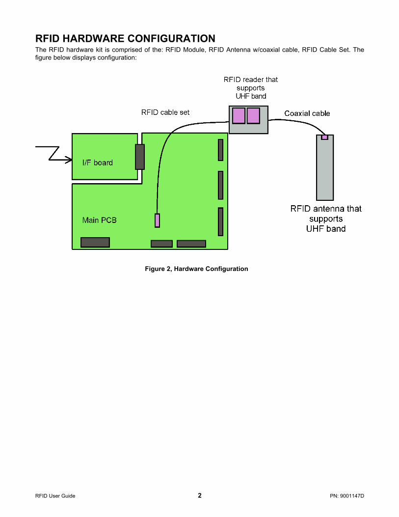
RFID HARDWARE CONFIGURATIONThe RFID hardware kit is comprised of the: RFID Module, RFID Antenna w/coaxial cable, RFID Cable Set. Thefigure below displays configuration:
Figure 2, Hardware Configuration
RFID User Guide 2 PN: 9001147D
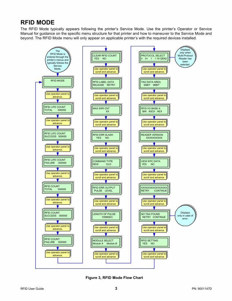
RFID MODEThe RFID Mode typically appears following the printer’s Service Mode. Use the printer’s Operator or ServiceManual for guidance on the specific menu structure for that printer and how to maneuver to the Service Mode andbeyond. The RFID Mode menu will only appear on applicable printer’s with the required devices installed.
Figure 3, RFID Mode Flow Chart
Use operator panel to advance.
RFID MODE
PROTOCOL SELECT0 0+ 1 1.19 GEN2
Use operator panel to scroll and advance.
Use operator panel to scroll and advance.
Use operator panel to scroll and advance.
LENGTH OF PULSE 100MSEC
Use operator panel to scroll and advance.
Use operator panel to scroll and advance.
Use operator panel to scroll and advance.
Use operator panel to scroll and advance.
Use operator panel to scroll and advance.
Use operator panel to scroll and advance.
Use operator panel to scroll and advance.
Use operator panel to scroll and advance.
Use operator panel to advance.
Use operator panel to advance.
Use operator panel to advance.
Use operator panel to advance.
Use operator panel to advance.
MAX ERR CNT XX
RFID COUNTSUCCESS 000000
RFID COUNTTOTAL 000000
RFID LIFE COUNTFAILURE 000000
RFID LIFE COUNTTOTAL 000000
RFID LIFE COUNTSUCCESS 000000
RFID LABEL DATARELEASE RETRY
RFID COUNTFAILURE 000000
RFID ERR SLASH YES NO
RFID I/O BASE-X BIN ASCII HEX
VIEW EPC DATA YES NO
COMMAND TYPENEW OLD
RFID ERR OUTPUT PULSE LEVEL
READER VERSIONXXXXXXXXXX
TAG DATA AREA 64BIT 96BIT
XXXXXXXXXXXXXXXXRETRY CONTINUE
NO TAG FOUND RETRY CONTINUE
RFID SETTING YES NO
The RFID Mode is
entered through the printer’s menus and typically follows the
ServiceMode.
Use operator panel to advance.
Use operator panel to scroll and advance.
Use operator panel to scroll and advance.
Use operator panel to scroll and advance.
MODULE SELECTModule A Module B
CLEAR RFID COUNT YES NO
Use operator panel to scroll and advance.
Use operator panel to scroll and advance.
Displays only when
Multi-Protocol Reader has
been selected.
Displays only in case of
error.
RFID User Guide 3 PN: 9001147D
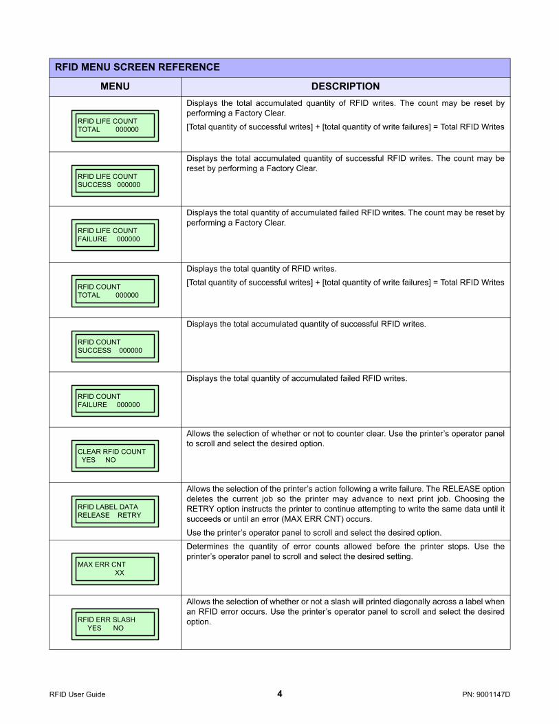
RFID MENU SCREEN REFERENCE
MENU DESCRIPTIONDisplays the total accumulated quantity of RFID writes. The count may be reset byperforming a Factory Clear.
[Total quantity of successful writes] + [total quantity of write failures] = Total RFID Writes
Displays the total accumulated quantity of successful RFID writes. The count may bereset by performing a Factory Clear.
Displays the total quantity of accumulated failed RFID writes. The count may be reset byperforming a Factory Clear.
Displays the total quantity of RFID writes.
[Total quantity of successful writes] + [total quantity of write failures] = Total RFID Writes
Displays the total accumulated quantity of successful RFID writes.
Displays the total quantity of accumulated failed RFID writes.
Allows the selection of whether or not to counter clear. Use the printer’s operator panelto scroll and select the desired option.
Allows the selection of the printer’s action following a write failure. The RELEASE optiondeletes the current job so the printer may advance to next print job. Choosing theRETRY option instructs the printer to continue attempting to write the same data until itsucceeds or until an error (MAX ERR CNT) occurs.
Use the printer’s operator panel to scroll and select the desired option.
Determines the quantity of error counts allowed before the printer stops. Use theprinter’s operator panel to scroll and select the desired setting.
Allows the selection of whether or not a slash will printed diagonally across a label whenan RFID error occurs. Use the printer’s operator panel to scroll and select the desiredoption.
RFID LIFE COUNTTOTAL 000000
RFID LIFE COUNTSUCCESS 000000
RFID LIFE COUNTFAILURE 000000
RFID COUNTTOTAL 000000
RFID COUNTSUCCESS 000000
RFID COUNTFAILURE 000000
CLEAR RFID COUNT YES NO
RFID LABEL DATARELEASE RETRY
MAX ERR CNT XX
RFID ERR SLASH YES NO
RFID User Guide 4 PN: 9001147D
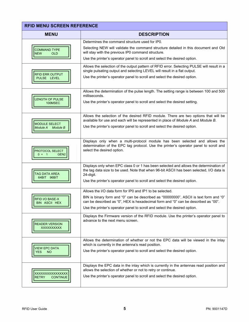
Determines the command structure used for IP0.
Selecting NEW will validate the command structure detailed in this document and Oldwill stay with the previous IP0 command structure.
Use the printer’s operator panel to scroll and select the desired option.
Allows the selection of the output pattern of RFID error. Selecting PULSE will result in asingle pulsating output and selecting LEVEL will result in a flat output.
Use the printer’s operator panel to scroll and select the desired option.
Allows the determination of the pulse length. The setting range is between 100 and 500milliseconds.
Use the printer’s operator panel to scroll and select the desired setting.
Allows the selection of the desired RFID module. There are two options that will beavailable for use and each will be represented in place of Module A and Module B.
Use the printer’s operator panel to scroll and select the desired option.
Displays only when a multi-protocol module has been selected and allows thedetermination of the EPC tag protocol. Use the printer’s operator panel to scroll andselect the desired option.
Displays only when EPC class 0 or 1 has been selected and allows the determination ofthe tag data size to be used. Note that when 96-bit ASCII has been selected, I/O data is24-digit.
Use the printer’s operator panel to scroll and select the desired option.
Allows the I/O data form for IP0 and IP1 to be selected.
BIN is binary form and “0” can be described as “00000000”, ASCII is text form and “0”can be described as “0”, HEX is hexadecimal form and “0” can be described as “00”.
Use the printer’s operator panel to scroll and select the desired option.
Displays the Firmware version of the RFID module. Use the printer’s operator panel toadvance to the next menu screen.
Allows the determination of whether or not the EPC data will be viewed in the inlaywhich is currently in the antenna’s read position.
Use the printer’s operator panel to scroll and select the desired option.
Displays the EPC data in the inlay which is currently in the antennas read position andallows the selection of whether or not to retry or continue.
Use the printer’s operator panel to scroll and select the desired option.
RFID MENU SCREEN REFERENCE
MENU DESCRIPTION
COMMAND TYPENEW OLD
RFID ERR OUTPUT PULSE LEVEL
LENGTH OF PULSE 100MSEC
MODULE SELECTModule A Module B
PROTOCOL SELECT 0 + 1 GEN2
PROTOCOL SELECT 0 + 1 GEN2
PROTOCOL SELECT 0 + 1 GEN2
TAG DATA AREA 64BIT 96BIT
RFID I/O BASE-X BIN ASCII HEX
READER VERSIONXXXXXXXXXX
VIEW EPC DATA YES NO
XXXXXXXXXXXXXXXXRETRY CONTINUE
RFID User Guide 5 PN: 9001147D
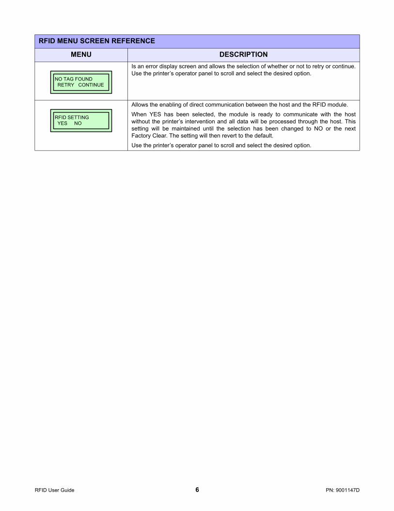
Is an error display screen and allows the selection of whether or not to retry or continue.Use the printer’s operator panel to scroll and select the desired option.
Allows the enabling of direct communication between the host and the RFID module.
When YES has been selected, the module is ready to communicate with the hostwithout the printer’s intervention and all data will be processed through the host. Thissetting will be maintained until the selection has been changed to NO or the nextFactory Clear. The setting will then revert to the default.
Use the printer’s operator panel to scroll and select the desired option.
RFID MENU SCREEN REFERENCE
MENU DESCRIPTION
NO TAG FOUND RETRY CONTINUE
RFID SETTING YES NO
RFID User Guide 6 PN: 9001147D

CALIBRATION MODEThe Calibration Mode typically appears following the RFID Mode. Use the printer’s Operator or Service Manual forguidance on the specific menu structure for that printer and how to maneuver to the Service Mode and beyond.The Configuration Mode menu will only appear on applicable printer’s with the required devices installed.
If using RFID labels that are printer specific, RFID transponder calibration is not necessary because the printer willautomatically place the labels in the optimal programming position. Contact SATO America Technical Support forinlay + placement specifications as necessary.
Where printer specific RFID labels are not to be used or in cases of new inlay types, RFID calibration may berequired to determine the optimal programming position and transmission/reception power conducive to thatmedia.
Figure 4, Calibration Mode Flow Chart
Use operator panel to scroll and advance.
ANTENNA POWER XXXmW
Labelprinted
Use operator panel to advance.
CALIBRATION MODE
Use operator panel to scroll and advance.
Use operator panel to scroll and advance.
Use operator panel to scroll and advance.
Use operator panel to advance.
Use operator panel to scroll and advance.
Use operator panel to scroll and advance.
Use operator panel to scroll and advance.
TAG OFFSET AUTO MANUAL
CALIBRATING. .P:XXX Ap:XX.XdBM
CAL. START YES NO
MAX. WRITE COUNT XXX
CAL. LABEL CNT 1 2 3
LABEL SIZE XXXMM
PRINT AGAIN YES NO
RFID TAG OFFSET +XXXmm
The Calibration Mode is entered through the printer’s menus and typically follows the
RFID Mode.
Use operator panel to scroll and advance.
SET LABEL YES NO
Use operator panel to scroll and advance.
CAL. OVERFINISH PRINT
RFID User Guide 7 PN: 9001147D
CALIBRATION MENU SCREEN REFERENCE
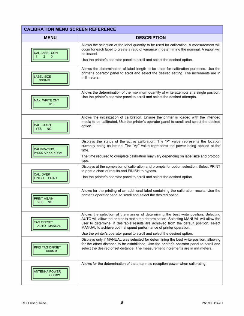
MENU DESCRIPTIONAllows the selection of the label quantity to be used for calibration. A measurement willoccur for each label to create a ratio of variance in determining the nominal. A report willbe issued.
Use the printer’s operator panel to scroll and select the desired option.
Allows the determination of label length to be used for calibration purposes. Use theprinter’s operator panel to scroll and select the desired setting. The increments are inmillimeters.
Allows the determination of the maximum quantity of write attempts at a single position.Use the printer’s operator panel to scroll and select the desired attempts.
Allows the initialization of calibration. Ensure the printer is loaded with the intendedmedia to be calibrated. Use the printer’s operator panel to scroll and select the desiredoption.
Displays the status of the active calibration. The “P” value represents the locationcurrently being calibrated. The “Ap” value represents the power being applied at thetime.
The time required to complete calibration may vary depending on label size and protocoltype.
Displays at the completion of calibration and prompts for option selection. Select PRINTto print a chart of results and FINISH to bypass.
Use the printer’s operator panel to scroll and select the desired option.
Allows for the printing of an additional label containing the calibration results. Use theprinter’s operator panel to scroll and select the desired option.
Allows the selection of the manner of determining the best write position. SelectingAUTO will allow the printer to make the determination. Selecting MANUAL will allow theuser to determine. If desirable results are achieved from the default position, selectMANUAL to achieve optimal speed performance of printer operation.
Use the printer’s operator panel to scroll and select the desired option.
Displays only if MANUAL was selected for determining the best write position, allowingfor the offset distance to be established. Use the printer’s operator panel to scroll andselect the desired offset distance. The measurement increments are in millimeters.
Allows for the determination of the antenna’s reception power when calibrating.
CAL.LABEL CON 1 2 3
LABEL SIZE XXXMM
MAX. WRITE CNT 010
CAL. START YES NO
CALIBRATING..P:XXX AP:XX.XDBM
CAL. OVERFINISH PRINT
PRINT AGAIN YES NO
TAG OFFSET AUTO MANUAL
RFID TAG OFFSET XXXMM
ANTENNA POWER XXXMW
RFID User Guide 8 PN: 9001147D

COMMAND STRUCTUREThis chapter provides the command sequences applicable to establishing RFID control through the use of anexternal host device instead of through the printer’s integrated operator panel.
EPC CODE WRITE DESIGNATION COMMAND (NEW)FUNCTION Writes EPC code in RFID supply that supports EPC code.
FORMAT <ESC>IP0e:z,d:xxxxxxxxxxxxxxxxxxxxxxxx;
PARAMETER x= EPC data
EXAMPLE <ESC>A
<ESC>V50<ESC>H50<ESC>XMTESTTEXT
<ESC>IP0e:z,d:123456781234567812345678;
<ESC>Q1
<ESC>Z
NOTES If the EPC code cannot be coded into the tag, an error message will print.
RFID User Guide 9 PN: 9001147D
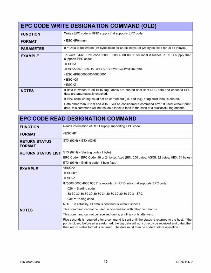
EPC CODE WRITE DESIGNATION COMMAND (OLD)FUNCTION Writes EPC code in RFID supply that supports EPC code.
FORMAT <ESC>IP0n.nnn
PARAMETER n = Data to be written (16 bytes fixed for 64 bit inlays) or (24 bytes fixed for 96 bit inlays).
EXAMPLE To write 64-bit EPC code “8000 0000 4000 0001” for label issuance in RFID supply thatsupports EPC code:
<ESC>A
<ESC>V50<ESC>H50<ESC>BD3020654912345678904
<ESC>IP08000000040000001
<ESC>Q1
<ESC>Z
NOTES If data is written to an RFID tag, labels are printed after sent EPC data and encoded EPCdata are automatically checked.
If EPC code writing could not be carried out (i.e. bad tag), a tag error label is printed.
Data other than 0 to 9 and A to F will be considered a command error. If used without printdata, this command will not cause a label to feed in the case of a successful tag encode.
EPC CODE READ DESIGNATION COMMANDFUNCTION Reads information of RFID supply supporting EPC code.
FORMAT <ESC>IP1
RETURN STATUS FORMAT
STX (02H) + ETX (03H)
RETURN STATUS LIST STX (02H) = Starting code (1 byte)
EPC Code = EPC Code; 16 or 24 bytes fixed (BIN: 256 bytes, ASCII: 32 bytes, HEX: 64 bytes)
ETX (03H) = Ending code (1 byte fixed)
EXAMPLE <ESC>A
<ESC>IP1
<ESC>Z
If “8000 0000 4000 0001” is recorded in RFID inlay that supports EPC code:
02H = Starting code
38 30 30 30 30 30 30 30 34 30 30 30 30 30 30 31 EPC
03H = Ending code
NOTE: In actuality, all data is continuous without spaces.
NOTES This command cannot be used in combination with other commands.
This command cannot be received during printing - only afterward.
Five seconds is required after a command is sent until the status is returned to the host. If theport is closed before all are returned, the tag data will not correctly be received and data otherthan return status format is returned. The data must then be sorted before operation.
RFID User Guide 10 PN: 9001147D

EPC TRADE MARK PRINT COMMANDFUNCTION Specifies the print of EPC trademark on a tag label.
FORMAT <ESC>TMx
PARAMETER
x = Logo ID number 0 1
EXAMPLE <ESC>A
<ESC>V50<ESC>H50<ESC>TM1<ESC>Q1
<ESC>Z
NOTES Rotation <ESC>% and Enlargement <ESC>L are also available.
Specify the command Enlargement <ESC>L right before <ESC>TM in case of its usage.
The original print area is of 143W x 101H dots (without the designation of enlargement).
When parameter “x” is left blank, logo “1” will be printed.
RFID User Guide 11 PN: 9001147D
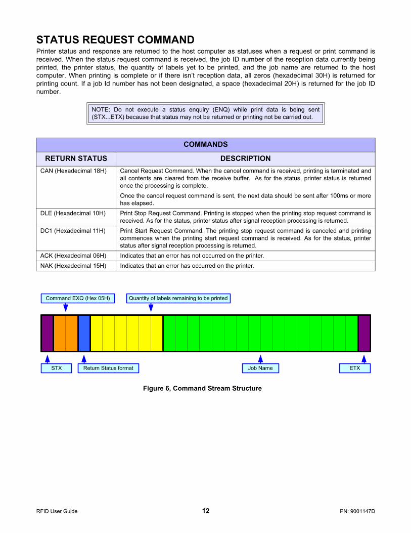
STATUS REQUEST COMMANDPrinter status and response are returned to the host computer as statuses when a request or print command isreceived. When the status request command is received, the job ID number of the reception data currently beingprinted, the printer status, the quantity of labels yet to be printed, and the job name are returned to the hostcomputer. When printing is complete or if there isn’t reception data, all zeros (hexadecimal 30H) is returned forprinting count. If a job Id number has not been designated, a space (hexadecimal 20H) is returned for the job IDnumber.
Figure 6, Command Stream Structure
NOTE: Do not execute a status enquiry (ENQ) while print data is being sent(STX...ETX) because that status may not be returned or printing not be carried out.
COMMANDS
RETURN STATUS DESCRIPTIONCAN (Hexadecimal 18H) Cancel Request Command. When the cancel command is received, printing is terminated and
all contents are cleared from the receive buffer. As for the status, printer status is returnedonce the processing is complete.
Once the cancel request command is sent, the next data should be sent after 100ms or morehas elapsed.
DLE (Hexadecimal 10H) Print Stop Request Command. Printing is stopped when the printing stop request command isreceived. As for the status, printer status after signal reception processing is returned.
DC1 (Hexadecimal 11H) Print Start Request Command. The printing stop request command is canceled and printingcommences when the printing start request command is received. As for the status, printerstatus after signal reception processing is returned.
ACK (Hexadecimal 06H) Indicates that an error has not occurred on the printer.
NAK (Hexadecimal 15H) Indicates that an error has occurred on the printer.
Command EXQ (Hex 05H) Quantity of labels remaining to be printed
Job NameReturn Status formatSTX ETX
RFID User Guide 12 PN: 9001147D

RETURN STATUS LISTCONTENTS ASCII HEX
OFFLINE STATUS
No error 0 30
Ribbon near end 1 31
Buffer near full 2 32
Ribbon near end & buffer near full 3 33
Printing stopped (no error) 4 34
ONLINE STATUS
Reception Standby No error A 41
Ribbon near end B 42
Buffer near full C 43
Ribbon near end & buffer near full D 44
Printing stopped (no error) E 45
Printing No error G 47
Ribbon near end H 48
Buffer near full I 49
Ribbon near end & buffer near full J 4A
Printing stopped (no error) K 4B
Standby No error M 4D
Ribbon near end N 4E
Buffer near full O 4F
Ribbon near end & buffer near full P 50
Printing stopped (no error) Q 51
Analysis/Editing No error S 53
Ribbon near end T 54
Buffer near full U 55
Ribbon near end & buffer near full V 56
Printing stopped (no error) W 57
ERROR DETECTION
Head open b 62
Paper end c 63
Ribbon end d 64
Media error e 65
Sensor error f 66
Head error g 67
Cover open h 68
Card error i 69
Cutter error (CL4e only) j 6A
Other errors k 6B
Cutter sensor error (CL4e only) l 6C
Stacker or rewinder full (CL4e only) m 6D
RFID STATUS Successful write n 6E
Failed write o 6F
RFID User Guide 13 PN: 9001147D

EXT CONNECTORThe EXT Port pin-out information for the RFID has changed to accommodate the addition of a “tag error” output.
Figure 7, EXT Connector
PIN ASSIGNMENTS
PIN DESCRIPTION DIRECTION1 Media Out - Pin goes low (0V) when label or ribbon is out. Output
2 Signal Ground Reference
3 RFID Tag Error - Pin goes low (0V) when a bad RFID tag is identified. Output
4 Printer Error - Pin goes low (0V) when the printer detects an error condition such as head open,receiving buffer full or when the user specified number of RFID errors has been reached.
Output
5 Print Start - The printer will print one label when this pin is pulled to ground. Input
6 End Print - Used to drive external devices requiring synchronization with the print cycle. Output
7 Reprint - Prints a duplicate of the last label when this signal is received. Input
8 Reserved. Input
9 Offline - Pin goes low (0V) when the printer is offline. Output
10 Ribbon Near End - Pin goes high when the amount of ribbon on the unwind shaft isapproximately 46 feet (14 m). The output will be low when the ribbon is gone.
Output
11 Reserved Output
12 +24 +/- 10% @ 2A - Power for external devices. Output
13 Vcc - +5V Output
14 Frame Ground Reference
RFID User Guide 14 PN: 9001147D
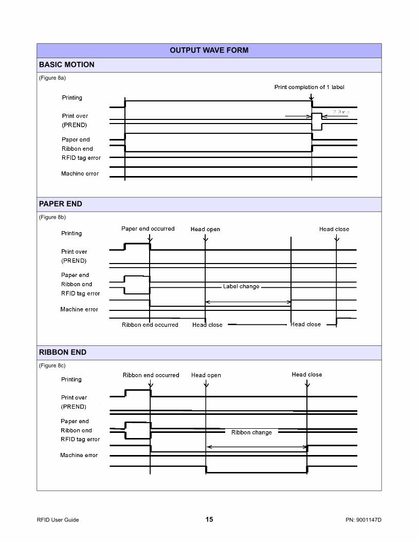
OUTPUT WAVE FORM
BASIC MOTION(Figure 8a)
PAPER END(Figure 8b)
RIBBON END(Figure 8c)
RFID User Guide 15 PN: 9001147D
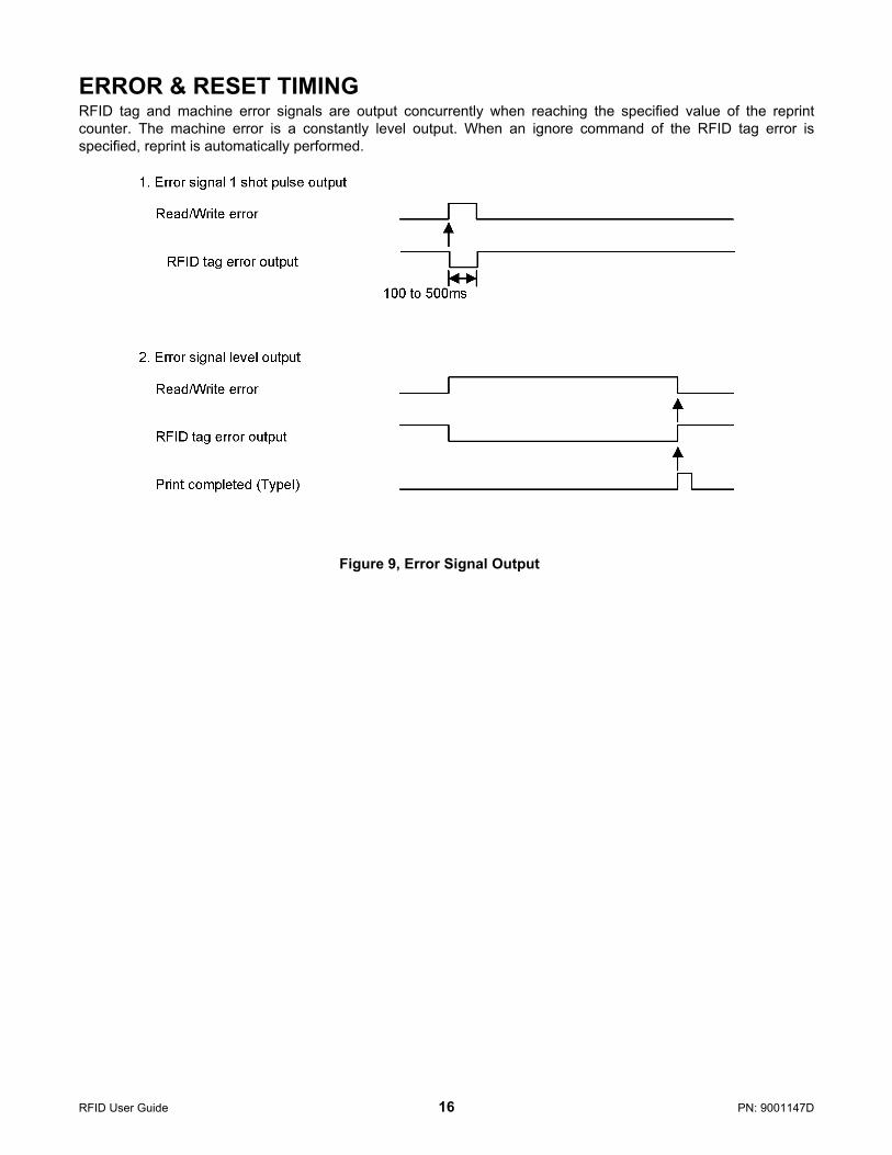
ERROR & RESET TIMINGRFID tag and machine error signals are output concurrently when reaching the specified value of the reprintcounter. The machine error is a constantly level output. When an ignore command of the RFID tag error isspecified, reprint is automatically performed.
Figure 9, Error Signal Output
RFID User Guide 16 PN: 9001147D
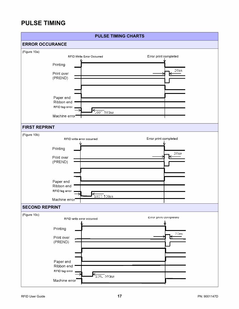
PULSE TIMING
PULSE TIMING CHARTS
ERROR OCCURANCE(Figure 10a)
FIRST REPRINT(Figure 10b)
SECOND REPRINT(Figure 10c)
RFID User Guide 17 PN: 9001147D
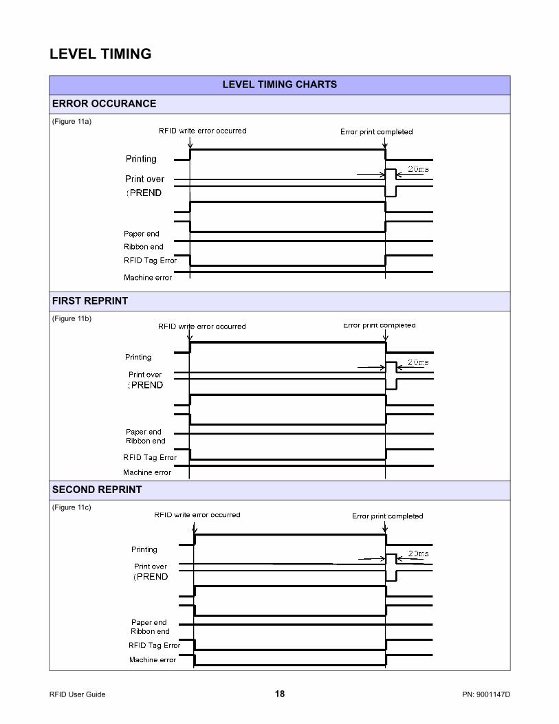
LEVEL TIMING
LEVEL TIMING CHARTS
ERROR OCCURANCE(Figure 11a)
FIRST REPRINT(Figure 11b)
SECOND REPRINT(Figure 11c)
RFID User Guide 18 PN: 9001147D

+Open Label Gallery Plus. The following main menu screen will appear.
Figure 12, Screen 1
Click inside the label displayed on the screen and Screen 2 will appear. Select the appropriate RFID Printer Driverand any other options needed relative to the labels used (i.e.: dimensions, batch printing, cutter settings, etc.).
Figure 13, Screen 2
RFID User Guide 19 PN: 9001147D
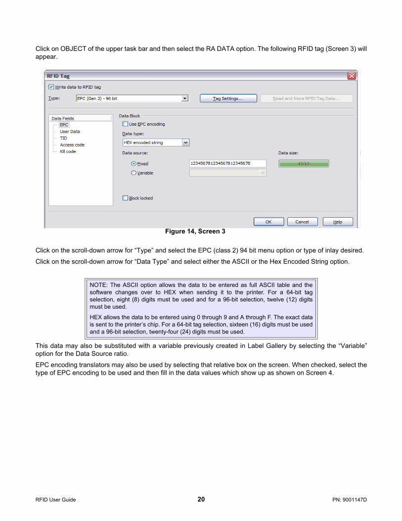
Click on OBJECT of the upper task bar and then select the RA DATA option. The following RFID tag (Screen 3) willappear.
Figure 14, Screen 3
Click on the scroll-down arrow for “Type” and select the EPC (class 2) 94 bit menu option or type of inlay desired.
Click on the scroll-down arrow for “Data Type” and select either the ASCII or the Hex Encoded String option.
This data may also be substituted with a variable previously created in Label Gallery by selecting the “Variable”option for the Data Source ratio.
EPC encoding translators may also be used by selecting that relative box on the screen. When checked, select thetype of EPC encoding to be used and then fill in the data values which show up as shown on Screen 4.
NOTE: The ASCII option allows the data to be entered as full ASCII table and thesoftware changes over to HEX when sending it to the printer. For a 64-bit tagselection, eight (8) digits must be used and for a 96-bit selection, twelve (12) digitsmust be used.
HEX allows the data to be entered using 0 through 9 and A through F. The exact datais sent to the printer’s chip. For a 64-bit tag selection, sixteen (16) digits must be usedand a 96-bit selection, twenty-four (24) digits must be used.
RFID User Guide 20 PN: 9001147D

Figure 15, Screen 4
Click on the OK button when complete and the label will display on the next screen with the RFID inlay outlinedaround the label. Refer to Screen 5.
RFID User Guide 21 PN: 9001147D
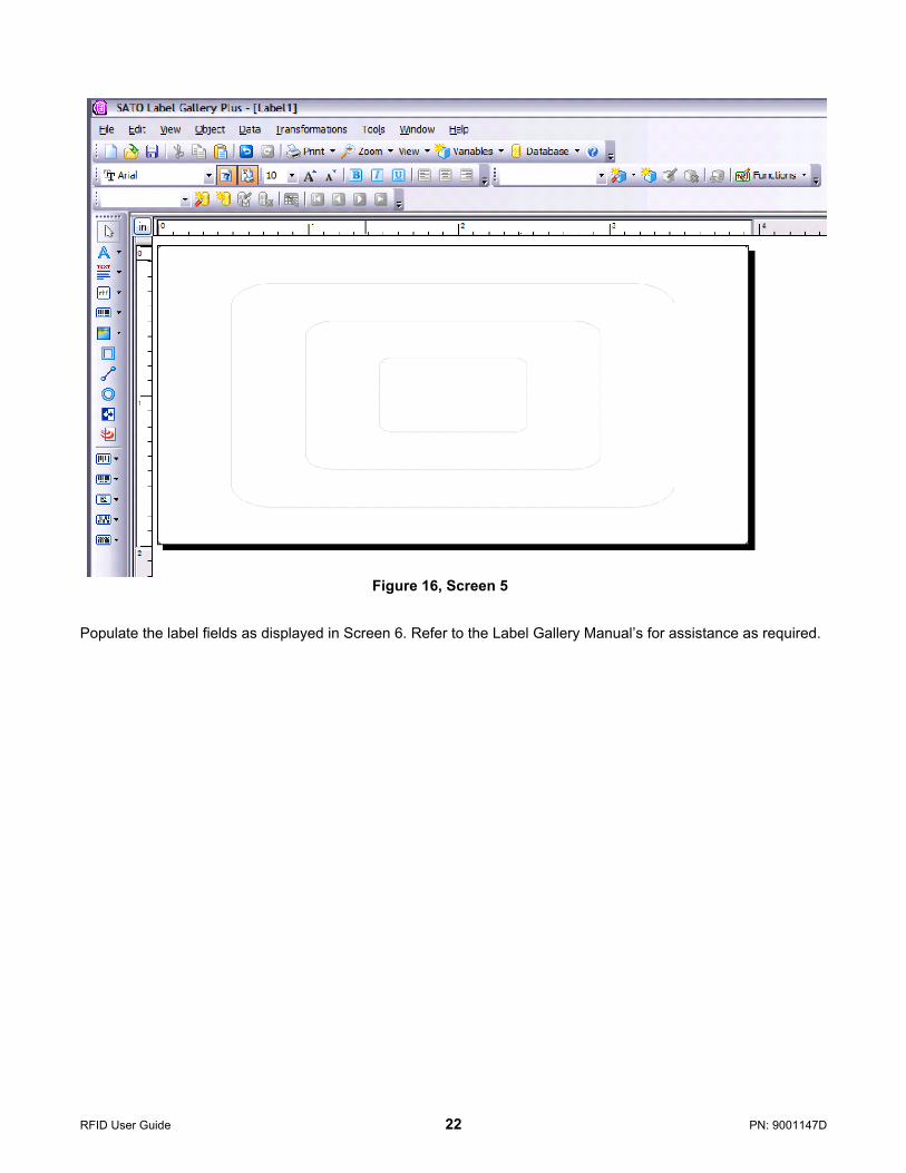
Figure 16, Screen 5
Populate the label fields as displayed in Screen 6. Refer to the Label Gallery Manual’s for assistance as required.
RFID User Guide 22 PN: 9001147D
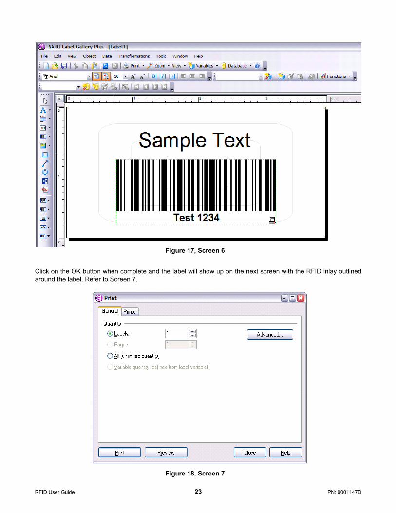
Figure 17, Screen 6
Click on the OK button when complete and the label will show up on the next screen with the RFID inlay outlinedaround the label. Refer to Screen 7.
Figure 18, Screen 7
RFID User Guide 23 PN: 9001147D

This page left blank intentionally.
RFID User Guide 24 PN: 9001147D


