87
1 Dr Youssef Hammida Diaphragm For Seismic Analysi s ﺗﺻﻣﯾم ﺑﻼطﺔ اﻟدﯾﺎﻓرام ﻟﻣﻘﺎوﻣﺔ ﻗو ى اﻟزﻻزلRigid – Semi Rigid - Flixible
| Date post: | 11-Jan-2017 |
| Category: |
Engineering |
| Upload: | dryoussef-hammida |
| View: | 547 times |
| Download: | 18 times |

1
Dr Youssef Hammida
Diaphragm For Seismic Analysis
الزالزل ىقو لمقاومة تصمیم بالطة الدیافرام
Rigid – Semi Rigid - Flixible
2
The rigid diaphragmالدیافرام الصلب
is a convenient analytical technique for distributing the lateral forces
to the frames and walls; forces are distributed to those elements as a
function of their relative stiffnesses and position.
Analysis using the rigid diaphragm assumption is generally adequate
when the diaphragm in-plane stiffness is high relative to that of the
frames.
There are some circumstances, however, where the rigid diaphragm
assumption may not be appropriate: floors with numerous openings,
roof diaphragms of metal decking without concrete fill or of plywood
sheathing, etc. Long, narrow diaphragms may be considered rigid in
one direction but not in the other.
For structures with multiple wings, such as L- or C-shaped buildings
where the ends of the wings can drift independently of each other,
the rigid diaphragm analysis may not be appropriate since it would
lock the ends of the wings together, constraining them to move in
unison.
In these cases it may be necessary or required to analyze the
structure modeled with semi-rigid diaphragms. It is often appropriate
to analyze some stories using the rigid diaphragm assumption and
other stories using the semi-rigid assumption.
ریاح والزالزلالدیافرام الصلب ھو الذي یحول الحموالت األفقیة من ال
الى العناصر الرأسیة من الجدران واألعمدة كل وفق صالبتھ
في التصمیم یمكن فرض الدیافرام صلب عندما تكون صالبتھ كبیرة
العناصر الرأسیة ومقارنتھا مع صالبة

3
أن یمكن األجنحة نھایات حیث C شكل على المباني أو -L مثل متعددة، أجنحة مع مباني ھیاكل
دیافرام صلب تحلیل یكون ال قد البعض، بعضھا عن مستقل بشكل تنتقل
من الحركة لھم وتقیید معا، األجنحة لنھایات قفل سیكون ألنھ ھو المناسب
لذلك یفضل دیافرام غیر صلب
diaphragm can be considered "flexible" if it is constructed of
untopped steel decking or wood structural panels and the structural
system is steel, concrete or masonry frames or walls, or when the
maximum in-plane deflection of the diaphragm under lateral load is
more than two times the average drift of the adjacent lateral frames.
In contrast, it specifies that a diaphragm can be considered "rigid" if it
is a concrete slab or concrete-filled metal deck, with some limitations.
Otherwise, the diaphragm must be modeled and analyzed as semi-
rigid.
It may also be more practical to analyze the diaphragms as semi-rigid
and avoid the need to perform the deflection calculations necessary
to classify the diaphragms otherwise.
It is permissible in any case to model and analyze the diaphragm as
semi-rigid.

4
الدیافرامات التي ال تحوي بالطة خرسانة مسلحة مثل السقف
الخشبي والمعدني من الواح الصاج الفوالذي یمكن اعتبارھا غیر صلبة
یمكن فرض الدیافرام شبھ صلب عوضا عن اجراء الحساب الالزم لإلنتقاالت
ویمكن مباشرة التصمیم وقبول فرض الدیافرام نصف او شبھ
كان صلباصلب حتى ولو
Diaphragm": "لدیافراما
األفقیة التي تقوم بنقل األحمال المستویة یطلق على العناص
المرتبطة بھا ارأسیة في مستویھا إلى العناصر االخرى من الریاح والزالزل
عندما تقوم بنقل األحمال الجانبیة الناتجة عن القوى صلبة حیث تعتبر البالطات دیافرامات
.الزلزالیة أو الریاح إلى العناصر الراسیة كاالعمدة وحوائط القص
وتوزع القوى الى العناصر كل وفق صالبتھ

5
ویتأثر الدیافرام سواء كان صلب او مرن فھو یعتمد
بصالبة العناصر الرأسیة
في الدیافرام المرن الحموالت األفقیة تنتقل الى المساند -
المساحات من البالطة على طرفيالجدران بطریقة منصف
الجدار كما في حال حساب حمولة العامود
6
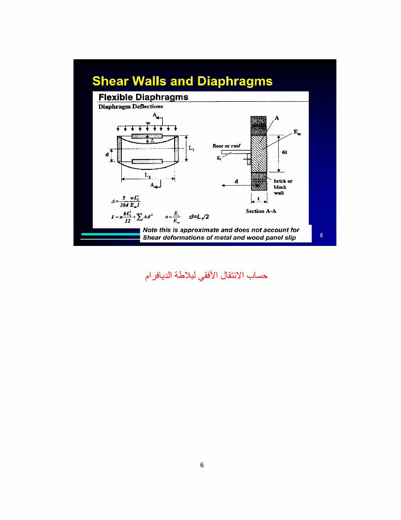
حساب االنتقال األفقي لبالطة الدیافرام

7

8
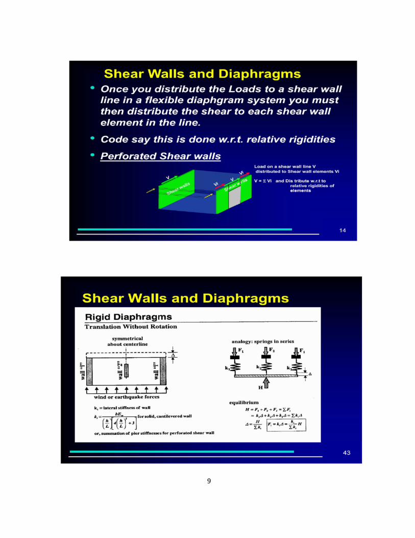
حساب حصة الجدران من القص وفق صالبة
الجدران في دیافرام صلب
9

10
كیفیة انتقال قوى القص القاعدي بین بالطات الدیافرام
من األعلى الى األسفل

11
المرن -شبھ صلب –الدیافرام = الصلب

12
انتقال قوى القص من بالطة الدیافرام الى الجدران
كمرة مدفونة – وفق مسارات ومجمعات قصیة

13
اختیار نوع الدیافرام حددھا الكود وفق سماكة
بالطة الدیافرام ونوعیة المادة
فكل بالطات الخرسانة المسلحة بانواعھا -
التغطیة في المسیق الصنعحتى بالطات
صلبة Rigid تعتبر
انتقال دیافرام وبعض الكودات یتطلب حساب-
بالطة السقف ضمن حدود معینة واال تعتبر
– semi
اما باقى بالطات واسقف الستیل المعدنیة
من الواح الصاج والصندویش العازل
flexibleفتعتبر مرنة
14
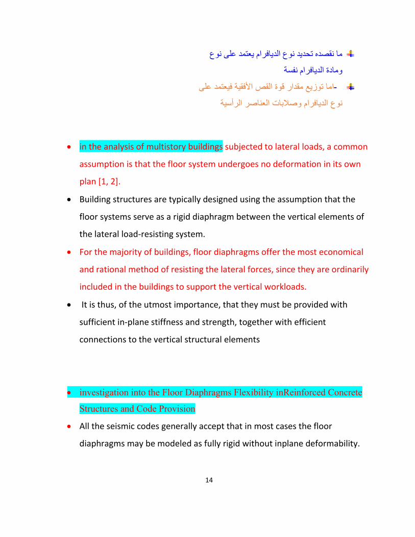
یعتمد على نوع ما نقصده تحدید نوع الدیافرام
ومادة الدیافرام نفسة
اما توزیع مقدار قوة القص األفقیة فیعتمد على -
نوع الدیافرام وصالبات العناصر الرأسیة
in the analysis of multistory buildings subjected to lateral loads, a common
assumption is that the floor system undergoes no deformation in its own
plan [1, 2].
Building structures are typically designed using the assumption that the
floor systems serve as a rigid diaphragm between the vertical elements of
the lateral load-resisting system.
For the majority of buildings, floor diaphragms offer the most economical
and rational method of resisting the lateral forces, since they are ordinarily
included in the buildings to support the vertical workloads.
It is thus, of the utmost importance, that they must be provided with
sufficient in-plane stiffness and strength, together with efficient
connections to the vertical structural elements
investigation into the Floor Diaphragms Flexibility inReinforced Concrete
Structures and Code Provision
All the seismic codes generally accept that in most cases the floor
diaphragms may be modeled as fully rigid without inplane deformability.

15
Even though a rigid floor diaphragm is a good assumption for seismic
analysis of the most buildings, several building configurations may exhibit
significant flexibility in floor diaphragms.
In these configurations, some codes like (EC8, NZS4203, GSC- 2000) set
certain qualitative criteria related to the shape of the diaphragm, while
some others (2800, UBC-97, SEAOC-90, FEMA-273) set quantitative criteria
relating the in-plane deformation of the diaphragm with the average drift
of the associated storey

16
من نوع الدیافرام صلب ام شبھ صلب وذلك بحسابالتحقق
انتقال الدیافرام وانتقال العنصر الراسي
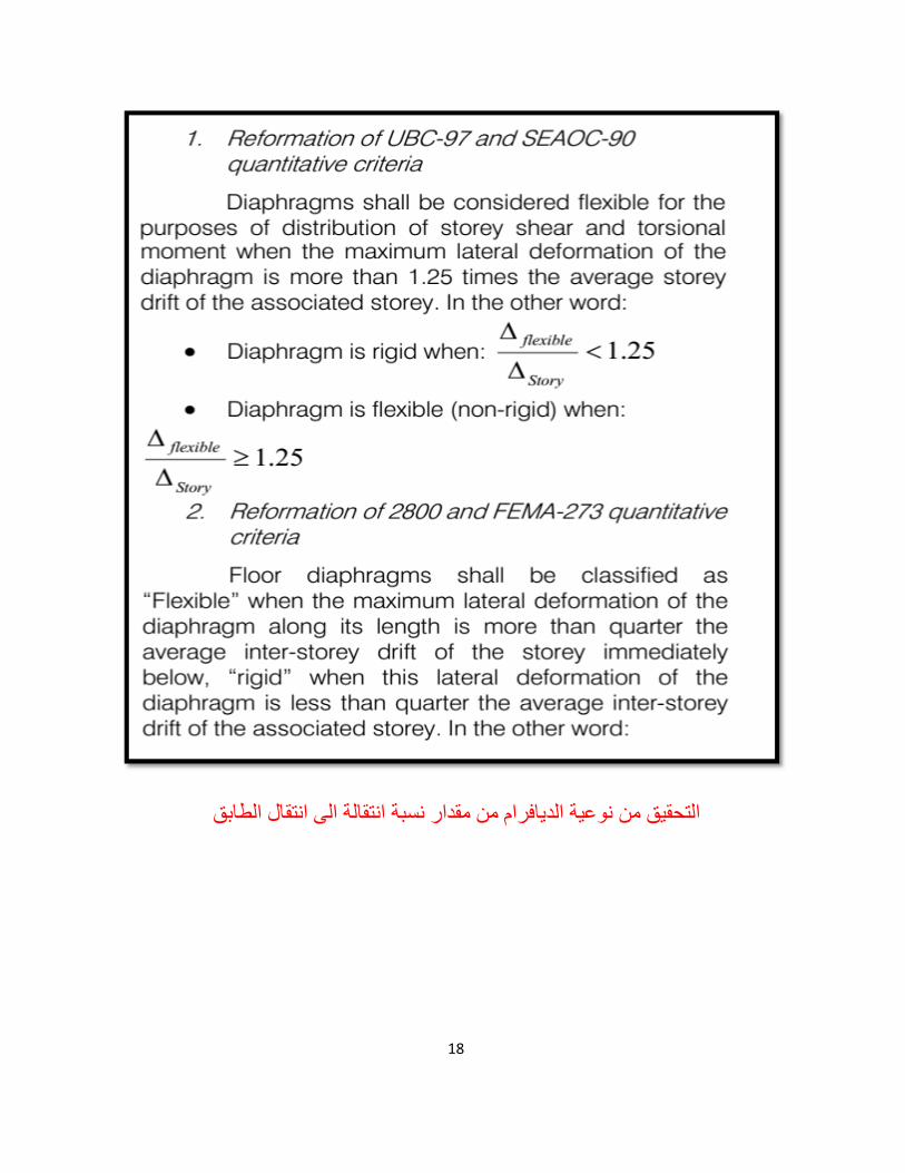
A. Floor diaphragms shall be classified as either
“flexible”, “stiff”, or “rigid”.
B. “Flexible” when the maximum lateral deformation of the diaphragm along
its length is more than twice the average inter-storey drift of the storey
immediately below ( λ ≥ 2 ),
C. “rigid” when this
lateral deformation of the diaphragm is less than half the
average inter-storey drift of the associated storey (
λ < 5.0 ) and
D. “stiff” when the diaphragm it is neither
flexible nor rigid ( 0. λ <≤ 25 ).

17
حساب قوى مثلث القص القاعدى التى تعمل في بالطات الدیافرام
في كل طابق
18
الدیافرام من مقدار نسبة انتقالة الى انتقال الطابق یةنوع من تحقیقال

19
Eccentricity – For rigid diaphragms, the accidental eccentricity associated with seismic loading is concentrated
and applied at the center of mass, whereas for semi-rigid diaphragms,
accidental eccentricity is applied to every node for seismic loads.
If no diaphragm is assigned eccentricity will not be applied to any node.
For wind cases and rigid diaphragm, load is applied at geometric centroid,
in case of semi-rigid diaphragm loads are distributed in 10 nodes, so that
the summation of these forces with respect to centroid will be equivalent
to lateral and torsional wind cases.
Reporting forces – In-plane chord, shear, and collector forces are only
reported when using semi-rigid diaphragms.
تطبق في مركز الكتلة الدیافرام الصلب قوى العطالة في
لكن في حال الدیافرام غیر صلب تطبق في عقد األعمدة والجدران
Forces in diaphragms under earthquakes ‘Inertia’ forces – Inertia at a particular floor • ‘Transfer’ forces – Forces develop between primary lateral force resisting structures

20
– These forces are often very large. Force distribution in a floor diaphragm = Inertia + Transfer forces
Floor plan configuration issues
دیافرام األشكال الغیر منتظمة یقضل قرضھا في التصمیم شبھ صلبىة
حركةاو الفصل بین األجنحة وحریة ال
:( rigid diaphragm)دیافرام صلب
أي أن البالطة ذات صالبة كبیرة وبالتالي ال یحدث تشوه في مستوي البالطة و یكون توزیع األحمال على العناصر اإلنشائیة تبعا لنسب جسائتھا
(Simi rigid diaphragm دیافرام شبھ صلب
أي أن صالبة الدیافرام غیر كافیة و یحدث تشوه في مستوي البالطة وبالتالي ال یكون توزیع األحمال
على العناصر اإلنشائیة تبعا لنسب جسائتھا

21
عندما یكون االنتقال الجانبي األعظمي للدیافرام أكبر من ضعفي متوسط اإلزاحة للطابق المرافق.
المحسوبة في المستوي األفقي للنقطة في منتصف المسافة للدیافرام ویمكن تحدید ذلك بمقارنة اإلزاحة
ذاتھ، بتأثیر الحمل الجانبي، مع إزاحة الدور للعناصر الرأسیة
.عندما یكون وجود انقطاعات في بعض أجزاء الدیافرام وبالتالي تنخفض صالبة البالطة
بالطة خرسانة او خشبیةالدیافرام المرن ھو للسقوف والبالطات المعدنیة ستیل دون
الديافرام الصلب يقوم بتوزيع القوى الجانبیة إلى العناصر المقاومة الرأسیة بحسب صالبة ھذه العناصر وھو ال ينحني تحت تأثیر القوى الجانبیة (أي ال
يتشوه) لذلك ھو قادر على نقل الفتل إلى العناصر المقاومة الرأسیة. إنشائي نحیف، ينحني تحت تأثیر القوى الجانبیة، أما الديافرام اللین فھو عنصر
لذلك ھو غیر قادر على نقل الفتل إلى العناصر المقاومة الرأسیة، ويعتمد على صالبة ھذه العناصر للحد من تشوھاته، وال يوزع القوى الجانبیة إلى العناصر
المقاومة الرأسیة بحسب صالبتھا، وإنما بحسب نسبة المساحة التي تحملھا .ھذه العناصر
تعتبر البالطة الخرسانیة ديافرام صلب أما الفوالذية الخفیفة والخشبیة فتعتبران
ديافرام لین.
وبما أن المطلوب ھو ديافرام السقف الصلب فھذا يعني أنه ال يتشوه عند تعرضه لقوة جانبیة، وبما أنه ال يتشوه فإنه يقوم بنقل الفتل أيضاً إلى العناصر المقاومة

22
تورشن –انتقال ودوران الدیافرام الصلب في تواجد فتل
المركزیة بین مركز الكتلة والصالبة للجدران القصیة

23
ا
اشكال غیر مفضلة وتواجد الفتحات والسالم والمصاعد
في الدیافرامات ویفضل تجنبھا

24
اشكال وانواع بالطات الدیافرام

25
Structural Behaviour of Diaphragms
نعمل الدیافرام ونقل القوى األفقیة الى الكور والجدرا كیفیة
Beam Analogy العمل الجائزي والكمرة العمیقة- deep beaam
تعمل البالطة كجائز عمیق مسنود على العناصر الرأسیة
من الكور والجدران واألعمدة وتتولد فیھا عزوم انحناء وقوى قص
ویجب ایجاد التسلیح الالزم لكل حالھ وقوى محوریة شادة ضاغطة
واضافتھ الى تسلیح الحموالت الشاقولیة

26

27

28

29
The code is allowing the designer to consider Rigid Diaphragm for reinforced concrete monolithic slab-beam floors or those consisting of prefabricated/ precast elements with topping reinforced screed.
The following condition has been proposed to evaluate the flexibility of a diaphragm.
حصة الجدار تصمیم كمرات مدفونة كلیكتور مجمعات لنقل
من القص من البالطة الى الجدار

30
انتقال الدیافرام وفق نوعھ وقیمة توزیع قوى القص
على الجدران وفق صالبة الدیافرام

31
الشاقولیة الحیة والمیتةاالضافھ لتصمیم البالطھ تحت االحمال ب وقوى القص مقدار قوه الشد و الضغط البد من التحقق من
التسلیح الالزمو حساب مقدار diaphragmالمتولده في ىالذي یقاوم ھذه القو

32

33

34
تصمیم بالطة الدیافرام كجائز عمیق
ایجاد مخطط العزم والجھد القاطع
عند األطراف وتسلیح القص العرضي ایجاد تسلیح االنعطاف
الكمراتكما العمل في
ثم تسلیح كلیكتور من القوى الشادة المساویة لقیمة رد الفعل األفقي
عند مساند الجدار

35
TYPES OF DIAPHRAGM
Rigid Diaphragms
A diaphragm may be considered rigid when its midpoint displacement, under lateral load, is less than twice the average displacements at its ends.
Rigid diaphragm distributes the horizontal forces to the vertical resisting elements in direct proportion to the relative rigidities.
It is based on the assumption that the diaphragm does not deform itself and will cause each vertical element to deflect the same amount.
Rigid diaphragms capable of transferring torsional and shear deflections and forces are also based on the assumption that the diaphragm and shear walls undergo rigid body rotation and this produces additional shear forces in the shear wall.
Rigid diaphragms consist of reinforced concrete diaphragms, precast concrete diaphragms, and composite steel deck.
36
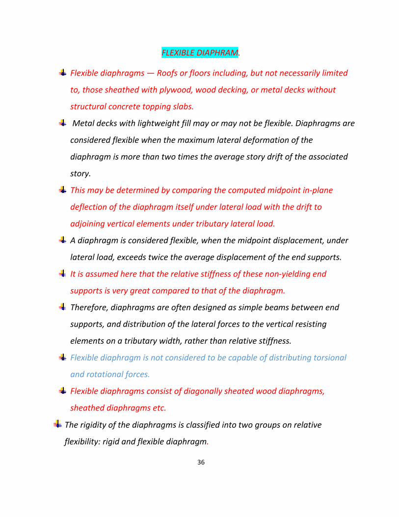
FLEXIBLE DIAPHRAM.
Flexible diaphragms — Roofs or floors including, but not necessarily limited
to, those sheathed with plywood, wood decking, or metal decks without
structural concrete topping slabs.
Metal decks with lightweight fill may or may not be flexible. Diaphragms are
considered flexible when the maximum lateral deformation of the
diaphragm is more than two times the average story drift of the associated
story.
This may be determined by comparing the computed midpoint in-plane
deflection of the diaphragm itself under lateral load with the drift to
adjoining vertical elements under tributary lateral load.
A diaphragm is considered flexible, when the midpoint displacement, under
lateral load, exceeds twice the average displacement of the end supports.
It is assumed here that the relative stiffness of these non-yielding end
supports is very great compared to that of the diaphragm.
Therefore, diaphragms are often designed as simple beams between end
supports, and distribution of the lateral forces to the vertical resisting
elements on a tributary width, rather than relative stiffness.
Flexible diaphragm is not considered to be capable of distributing torsional
and rotational forces.
Flexible diaphragms consist of diagonally sheated wood diaphragms,
sheathed diaphragms etc.
The rigidity of the diaphragms is classified into two groups on relative
flexibility: rigid and flexible diaphragm.

37

38

39

40

41
42
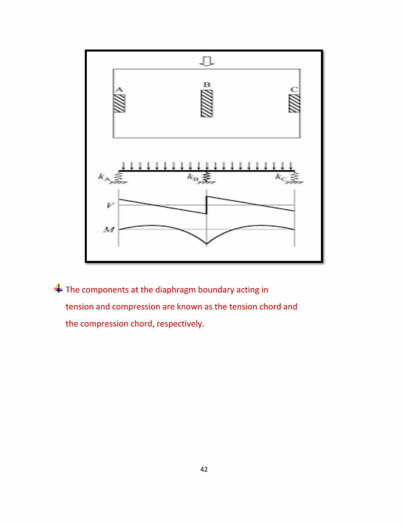
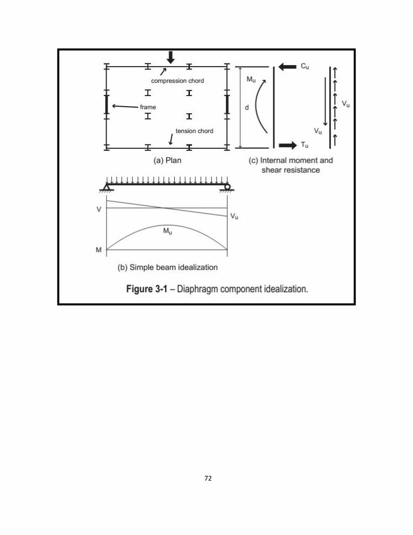
The components at the diaphragm boundary acting in
tension and compression are known as the tension chord and
the compression chord, respectively.

43
If the diaphragm moment is resisted by tension and compression
chords at the boundaries of the diaphragm as shown in Figure
3-1a, then equilibrium requires that the diaphragm shear be
distributed uniformly along the depth of the diaphragm as
shown in Figure 3-1c.
Tension and compression elements
called collectors are required to “collect” this shear and transmit
it to the walls
A collector can transmit all its forces into the
ends of the walls as shown on the right side of Figure 3-2a,
or if the forces and resulting congestion are beyond practical

44
limits, the collector can be spread into the adjacent slab as
shown on the left side of Figure 3-2a.
Figure 3-3. As used in this Guide, a collector is an element that takes distributed
load from the diaphragm and delivers it to a vertical element, whereas a
distributor takes force from a vertical element and distributes it into the diaphragm.
وكمرات مدفونة في سقف طابق األقبیة صلب تأمین دیافرام
األقبیة -م لتحویل قوى القص الى جدران البدرومالبدرو

45
In addition, the inclined ramps can act as unintended diagonal braces
that interrupt intended framing action of the vertical elements and result
in considerable axial load in the diaphragm. Expansion joints can relieve
this action
if provided at every level.

46
السیاراتفي حال تواجد بالطات الساللم ورمب
یجب تصمیم بالطة الدیافرام على قوى الضغط
عند اتصال البالطة المائلة مع السقف األفقي

47
حال تواجد فتحات كبیرة في بالطة الدیافرام في
فیجب تصمیم جوانب الفتحات على القوى الشادة
الضاغطة

48
كذلك في حال شكل بالطة الدیافرام غیر منتظم ویحوي كسرات
كلیكتور -یجب وضع كمرات مدفونة وتسلیح المجمع او رجوعات

49
القوى األفقیة من الریاح او الزالزل ھي دائما
موجودة وموزعة بانتظام في بالطة الدیافرام

50
توزع قوى الریاح او الزالزل وانتقالھا
الى بالطات الدیافرام السفلي

51
كمرة عمیقة -تصیم بالطة الدیافرام مثل جائز
التسلیح الالزم من العزم والقصوایجاد
واضافتھ الى مقطع التسلیح الشاقولي
52

53
الدیافرام المستمر المرن یقایلھ كمرة عمیقة على مساند مرنة مستمرة

54
Horizontal Diaphragms of Complex shape

55

56

57
diaphragm ACI 318 -14 كود امریكي –

58

59

60

61

62
What is the center of rigidity for a semi-rigid diaphragm?
Answer: Center of rigidity is only applicable to rigid diaphragms because in-plane slab
deformation is variable across laterally loaded semi-rigid diaphragms.
During computation, an arbitrary coordinate is selected and loaded, then center of rigidity
is derived, as a function of stiffness, according to the displacement at this specific poin
ASCE 2009 -األمریكيالكود السوري الموافق للكود
63
diaphragm - دیافرام

64
65

66

67

68
Diaphragm Reinforcement

69
Large diameter diaphragm and collector reinforcing bars are
commonly spliced using mechanical couplers.
Because lap splices of No. 14 bars or larger are prohibited by ACI
318,mechanical couplers are required.
Location of Construction Joints
Construction joints create weakened planes within a diaphragm.
They can also impact development and splices of reinforcement.
Shear-friction reinforcement can be provided across construction
joints if necessary to maintain continuity of the diaphragm in
shear.
The impacts to the continuity and development of chord
and collector reinforcement at construction joints should also
be understood

70
seismic Design of Composite Steel Deck and Concrete-
filled Diaphragms
Flexibility of the diaphragm material. Among the usual building materials, wood or steel decking without concrete are the most flexible.
Aspect ratio (length/width) of the diaphragm. The greater the length/width ratio of the diaphragm, the greater the lateral distortions may be. In general, diaphragms with aspect ratios greater than 5 may be considered flexible.
Stiffness of the vertical structure. The flexibility of the diaphragm should also be judged in accordance with the distribution of rigid vertical elements in the plan. In the extreme case of a diaphragm in which llelements are of equal stiffness, better performance is expected than when there are major differences in this respect.

71
Openings in the diaphragm. Large openings in the diaphragm for purposes of illumination, ventilation, and visual connections between stories cause flexible areas that impede the rigid assembly of the vertical structures.
72

73

74

75

76

77

78
Shear Transfer
The strength of the diaphragm deck determined for the field of
the diaphragm must be adequately transferred to the perimeter
framing members if that strength is to be utilized.
A variety of fasteners can be utilized to accomplish this load transfer.
These include arc-spot (or puddle) welds, self-tapping/self
drilling screws, powder-actuated fasteners, and steel headedstud anchors.
Additionally, the side seam fastening can be accomplished using welds,
screws, or crimping, either traditional “button-punching” or proprietary
seaming.
As has already been mentioned, the side seam fastening has little
influence on composite deck diaphragm strength.
DESING EXAMPLE

79

80

81

82

83
Diaphragm forces- برنامج ایتاب

84

85

86

87


