10
I I I I I I I I RIV000130 Submitted: October 11, 2012

I
I
I
I
I
I
I
I
I
I
I
I
I
I
I
I
I
I
I
I
RIV000130 Submitted: October 11, 2012

r ~bntergy
uJtrasomc cxammauon l'(epon:
Sys./ Comp. ID: Main Feedwater I FW-02.4-15E
DWG No. or Sketch: 9321-F-20193 Rev. 56
QA Category: Non Cat ASME XI Class: N/A Cat: N/A
Component Configuration: Pipe to Elbow to Pipe.
Orientation: 0 Degree
Angle: 0 ° Mode: Longitudinal
Equipment
IPEC Unit# 3 Report No.: 03UT081 Page_1_of S
Exam Item: FW·02.4-15E I Pipe, Elbow, Pipe
WR/Mod: IPJ-02-24705
Procedure: NDEP 9.4-12(1) Rev.: 4
Type of Material:
Size: 30"
Carbon Steel
Thickness: 1.260"
002144201 Panametrics 36DL+ Due: 3/16/2004 Attenuator Linearity Check
Sianal1 1 ~·_uu I.':'!'. I_?X 1 }!". l_u~- 15'!'. ~-~~ 1 ,~ ~-~~ 1_~11_ I I so%~ 1
so%-12db I"0%+6dbp0%+rdb I N/A NfAN/A N/
(32 to 48) (16 to 24) (64·96) (64-96)
502080 Panametrics 5 Mhz 0.312" Round D791/ Dual Element Wedge: N/A 6' Self-Cont. Wedge Meas. Angle: N/A 0 Exit Point-Front:
Sonotech I Sono 600 Gel Thermometer: 103284 Due: 3/11/2004 103309 Step Wedge T= .75" • 1.5" Material: Carbon Steel
Simulator Block: N/A Reference Block: A13082 IIW-2 T= N/A Material: CARBON STEEL
N/A" Temperature
90 Of
N/A °F 78 °f
Entry Surface: OD Component:
Distance Amplitude Curve Instrument Settings Each Major Screen Division = 0.5"
%
':fl f± lilliE Orient. FSH Pos. dB -,·-step 80 2.0 N/A
Step 80 3.0 N/A
Range (in.): 5.0" Thick Cal: 2-PT Velocity (in./f.ls): 2332 Sensitivity (dB): 58
Step 80 8.0 N/A Scan Sensitivity 80% Frequency (mHz): 5
50 Reject: Off Filter: Full Pulse Length: Fixed Damping: Fixed Mode Select: Dual Rep. Rate: Fixed DEC/Gate: On ;~1111 ~ 111 II
'·······¥•······-¥·-·-
Calibration Times: 1 o945 I 1o3o]J1so I 1 -~
1 2 3 4 5 6 7 8 9 10 Jacks: T/R
Acceptance Standard: 87.5% of nominal as per AP-49 requirements. Recordable lndication(s}: Yes Recording Level: N/A% DAC Evaluation Level: N/A% DAC 100 %Complete Limitations: Integral Attachment Remarks: Recordable Indications reference page 2 & 4 of 5.
Obstruction due to Integral Attachment reference page 2 of 5. Reference page 4 of 5 for Lamination.
Examiner: cC,_- c::Z------ Christopher J. Danson Level: Ill Date: 3/31/2003
Examiner. ~~ Mich .. l W Julison Llllllii·IIL
Reviewed by: ~ ~ - Levet' J:1?t.
ANII Review: r; +
Date: 3/31/2003
Date: Y/3/~3-Date: ___ _
IPEC00020854
98 Of

'1J m () 0 0
2 0 OJ 01 01

'1J m () 0 0 0 1\.)
0 ()) 0'1 0')
NDEP 9.4· ,_,,, Rev.4 nent 2
·, _,., 1 of 1
• Report No.: 03UT081
~Entergy Page 2 of 5
Sys. I Comp. ID: Main Feedwater I FW-02.4-15E Material: Carbon Steel High Reading: 1.625" Exam Item: Pipe, Elbow,Pipe Size: 30" Low Reading: 0.513"
DWG No.: 9321-F-20193 rev. 56 Thickness: 1.260" Grid Size: 6" WR/Mod: IP3-02-24705 Configuration: See drawing below Datum Point: Outside Radius of Elbow QA Category: Non Cat. 1 ASME XI Class: N/A Cat: N/A
Acceptance Standard: 1.103" Procedure: NDEP 9.4-12 !Q Rev.: 4
FW-02.4-lSE
t.l/m; 11 a It~ '~'1 6" Grid Spacing
FW-02.4-15E-02
p A~ .- Integral 13 -· Attachment 7 17 A1 11
12
~ lr-
11 EW::Il2 !1-l§E::Il2
~ ~
Min: 0.513" FW.02.4-16P.03 ~ !
FW-02.4-lSE ;- i LOW READING
Looking DIS Max: 1.625" FW.02.4-15E.02 ~ 10
I ~
-- 0.496"
I' r-A1- \_ FW.027-16P-03
9
I Ellll::Q2 !1·l !iE::Il2 6 Obstruction due to
l~ Min: 1.348"
Integral Attachment EW.0~.~·14P.Oj
~ Max: 1.401" 8 AOS, A09 & A10
Min: 1.379" FW.02.4-14P.01 10
Max: 1.399"
I A1-~
7
6 A B c D E
Remarks: All thickness readings above are in thousandths of ce.-- £?__ an inch. Examiner: 6hristoeher J. Danson Level: Ill Date: 3/31/2003
For Min. & Max. Readings reference above Sketch. Examiner: JffaLJ, (/j_~tJ~/~.-.~ Low readings due to lamination. Michael W. Julison Level: IlL Date: 3/31/2003
Obstruction due to Integral Attachment see above. lt?z [j,J/ '7/2-/o:J Reviewed by: Level: rn- Date:
ANII Review: r-;J Date: Method Used: Grid Point Readings REA1-01
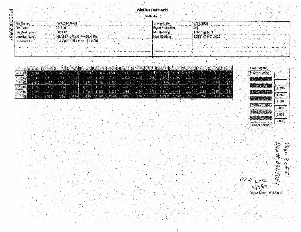
·. WinPiusoate.-f3rid · .. · rw-o2.4.:;" · .
' ;: •• v ,· '': • ~' ••
F< f~v£!1 ~. . "t['kll),.
R.epoit .Date: 3/3.112003

Report Date: :mt;2oo3· ·.

..... ·~. ··'· .... .
..... ~· .. ~: . .. :,.. '. ' ....
.·.~··.~·· ~·. ·~· .. ··
·~· .. Rl··
.~.· .. · .·~.· :"-.) . \
. \..S 10
\[~ ~ q{?.{o? •. . J..v1£'[::
~· ... ·-1). - \ ·•·()..,
~. I
"

8 7 6 5
D ®.
.
. .
c
B
A
8 7 5
.,..,,>;-·.:·· .. · .. ·
4.
to REVISIONS
2
· ·, ·. 11Ait la:·zaas .· . ·:',·:.·•>-.-.· •... ....•.. ,.,, ;,_'
~ ... ~. ' . c.~ .. .
··· ....
CH<•o INDIAN POINT NO.3 NUCLE "OES--SIP=Vc-· I .
=x"'""' EROSION GORROSIDN AUXILIARY SOILER .I
lnSCIPLli<E:OIR . BOILER-FEED PIPINI FROM 30'' HEADER T( ...-----'-tp ... RciruJ:APPiPAAiJ<OVWi••cc f, WATER LINES. IN AU.
""" BGI.LER BUILDJNG sc.o.~r
• NewYorkPower ·· · """ Allthorlty
2

1.
2.
3.
4.
5.
6.
7.
8.
,.
TRAVELER PACKAGE CHECKLIST
Preinspection b~efing given by Erosion/Corrosion Engineer ~%~··~~~ E/C ng. 0 e /
~ UTTech UTTech jJTTech UTTech
Traveler package contents __§f{_ ~ UTTech EIC Eng.
a. b. c. d.
Copy of procedure NDEP 9.4-12 Calibration sheet Drawing with point highlighted Data sheet
e. E/C Engineers phone number ~(-2{(:,· ··z. Location verified against drawing:
UTTech
Preinspection point setup per procedure NDEP-9.4-12: (If gridding is used) a. Correct grid size used b. Grid correctly laid out c. Grid lettered and numbered correctly d. Grid low stress stamped correctly e. Area up/downstream of component ~~o__1y laid out
Data Logger
a. b. c.
UTTech Inspection point used as file name Operators ID correct Instrument ID correct
Data Sheet
a. Flow direction correct b. Sketch drawn correctly c. Component number verified
Calibration Sheet correct
Daily review complete
if
urf ol ~· . ~7 03
t
~--
2 UTTech
~~ E/C Eng.
NOTE: • UT Technician sign-off is required prior to start of inspeCtion activity. • Engineering sign-off is required after verification of activity.
R12 Traveler
IPEC00020861

Inspection Point
Work Order
Pipe Size, inches
Tnom
Screen (87.5°/o Tnom)
Screen (70°/o Tnom)
Grid Size, in.
Pipe Class
INDIAN POINT 3 R012
FW-02.4-15E
I P3-02-24 705
30
1.260
1.103
0.882
6"
B-1
Pipe Spec, Grade A-672 Gr. 870 Class 21
Fitting Spec, Grade A-234 WPC
Schedule N/A
Design Pressure, psi 1440
Design Temperature °F 450
Allowable Stress, psi 17500
IPEC00020862


