272
ROBOTICS Product manual IRB 120
ROBOTICS
Product manualIRB 120

Trace back information:Workspace R17-2 version a11Checked in 2017-09-20Skribenta version 5.1.011

Product manualIRB 120 - 3/0.6
IRB 120T - 3/0.6IRC5
Document ID: 3HAC035728-001Revision: N
© Copyright 2009-2017 ABB. All rights reserved.

The information in this manual is subject to change without notice and should notbe construed as a commitment by ABB. ABB assumes no responsibility for any errorsthat may appear in this manual.Except as may be expressly stated anywhere in this manual, nothing herein shall beconstrued as any kind of guarantee or warranty by ABB for losses, damages topersons or property, fitness for a specific purpose or the like.In no event shall ABB be liable for incidental or consequential damages arising fromuse of this manual and products described herein.This manual and parts thereof must not be reproduced or copied without ABB'swritten permission.Keep for future reference.Additional copies of this manual may be obtained from ABB.
Original instructions.
© Copyright 2009-2017 ABB. All rights reserved.ABB AB, Robotics
Robotics and MotionSe-721 68 Västerås
Sweden

Table of contents9Overview of this manual ...................................................................................................................
14Product documentation, IRC5 ..........................................................................................................16How to read the product manual ......................................................................................................
171 Safety171.1 Introduction to safety information .........................................................................181.2 General safety information ..................................................................................181.2.1 Introduction to general safety information ....................................................191.2.2 Safety in the robot system ........................................................................211.2.3 Protective stop and emergency stop ...........................................................221.2.4 Safety risks ............................................................................................221.2.4.1 Safety risks during installation and service work on manipulators .........251.2.4.2 CAUTION - Hot parts may cause burns! ...........................................261.2.4.3 Safety risks related to tools/work pieces ..........................................271.2.4.4 Safety risks related to pneumatic/hydraulic systems ..........................281.2.4.5 Safety risks during operational disturbances .....................................291.2.4.6 Risks associated with live electric parts ...........................................311.2.5 Safety actions .........................................................................................311.2.5.1 Safety fence dimensions ...............................................................321.2.5.2 Fire extinguishing ........................................................................331.2.5.3 Emergency release of the robot arm ...............................................341.2.5.4 Brake testing ..............................................................................351.2.5.5 Risk of disabling function "Reduced speed 250 mm/s" ........................361.2.5.6 Enabling device and hold-to-run functionality ....................................371.2.5.7 Work inside the working range of the robot .......................................381.3 Safety signals and symbols .................................................................................381.3.1 Safety signals in the manual ......................................................................401.3.2 Safety symbols on product labels ...............................................................461.4 Safety related instructions ..................................................................................461.4.1 DANGER - Moving robots are potentially lethal! ............................................471.4.2 DANGER - First test run may cause injury or damage! ...................................481.4.3 DANGER - Make sure that the main power has been switched off! ....................501.4.4 WARNING - The unit is sensitive to ESD! .....................................................521.4.5 WARNING - Safety risks during handling of batteries .....................................531.4.6 WARNING - Safety risks during work with gearbox lubricants (oil or grease) ......
552 Installation and commissioning552.1 Introduction ......................................................................................................562.2 Unpacking .......................................................................................................562.2.1 Pre-installation procedure .........................................................................602.2.2 Working range and type of motion ..............................................................622.2.3 Risk of tipping/stability .............................................................................632.3 On-site installation ............................................................................................632.3.1 Lifting the robot with roundslings ...............................................................662.3.2 Manually releasing the brakes ...................................................................702.3.3 Orienting and securing the robot ...............................................................722.3.4 Fitting equipment on robot ........................................................................752.3.5 Setting the system parameters for a suspended or tilted robot .........................802.3.6 Loads fitted to the robot, stopping time and braking distances .........................812.4 Restricting the working range ..............................................................................812.4.1 Axes with restricted working range .............................................................822.4.2 Mechanically restricting the working range ...................................................842.5 Making robot ready for operation ..........................................................................842.5.1 Additional installation procedure, Clean Room ..............................................852.6 Electrical connections ........................................................................................852.6.1 Robot cabling and connection points ..........................................................
Product manual - IRB 120 53HAC035728-001 Revision: N
© Copyright 2009-2017 ABB. All rights reserved.
Table of contents

872.6.2 Customer connections on the robot ............................................................892.7 Start of robot in cold environments ......................................................................
913 Maintenance913.1 Introduction ......................................................................................................923.2 Maintenance schedule .......................................................................................923.2.1 Specification of maintenance intervals ........................................................933.2.2 Maintenance schedule .............................................................................953.3 Inspection activities ...........................................................................................953.3.1 Inspecting the robot cabling .....................................................................963.3.2 Inspecting mechanical stops ....................................................................993.3.3 Inspecting dampers .................................................................................
1013.3.4 Inspecting timing belts ............................................................................1053.3.5 Inspecting plastic covers ..........................................................................1073.4 Replacement/changing activities ..........................................................................1073.4.1 Type of lubrication in gearboxes ................................................................1093.4.2 Replacing the battery pack ........................................................................1123.5 Cleaning activities .............................................................................................1123.5.1 Cleaning the IRB 120 ...............................................................................
1154 Repair1154.1 Introduction ......................................................................................................1164.2 General procedures ...........................................................................................1164.2.1 Mounting instructions for seals ..................................................................1184.2.2 Replacing parts on the robot .....................................................................1204.3 Cable harness ..................................................................................................1204.3.1 Removing the cable harness .....................................................................1344.3.2 Refitting the cable harness ........................................................................1484.3.3 Replacing the Encoder Interface board ........................................................1514.4 Plastic covers ...................................................................................................1514.4.1 Replacing plastic covers ...........................................................................1554.5 Upper arm .......................................................................................................1554.5.1 Replacing the upper arm ..........................................................................1644.6 Lower arm .......................................................................................................1644.6.1 Replacing the lower arm ...........................................................................1694.7 Motors and motors with gearboxes .......................................................................1694.7.1 Replacing axis-1 motor with gearbox ..........................................................1904.7.2 Replacing axis-2 motor with gearbox ..........................................................2024.7.3 Replacing axis-3 motor with gearbox ..........................................................2104.7.4 Replacing motor axis 4, with gearbox ..........................................................2114.7.5 Replacing motor axis 5 .............................................................................2174.7.6 Replacing motor axis 6 .............................................................................2184.8 Gearboxes .......................................................................................................2184.8.1 Replacing gearbox axis 1 ..........................................................................2194.8.2 Replacing gearbox axis 2 ..........................................................................2204.8.3 Replacing gearbox axis 3 ..........................................................................2214.8.4 Replacing gearbox axis 4 ..........................................................................2224.8.5 Replacing gearbox axis 5 ..........................................................................2234.8.6 Replacing gearbox axis 6 ..........................................................................
2255 Calibration2255.1 Introduction to calibration ...................................................................................2255.1.1 Introduction and calibration terminology ......................................................2265.1.2 Calibration methods .................................................................................2275.1.3 When to calibrate ...................................................................................2285.2 Synchronization marks and axis movement directions .............................................2285.2.1 Synchronization marks and synchronization position for axes .........................2305.2.2 Calibration movement directions for all axes ................................................
6 Product manual - IRB 1203HAC035728-001 Revision: N
© Copyright 2009-2017 ABB. All rights reserved.
Table of contents

2315.3 Updating revolution counters ...............................................................................2355.4 Calibrating with Axis Calibration method ...............................................................2355.4.1 Description of Axis Calibration ..................................................................2375.4.2 Axis Calibration - Running the calibration procedure ......................................2425.5 Calibrating with manual calibration method ............................................................2485.6 Verifying the calibration ......................................................................................2495.7 Checking the synchronization position ..................................................................
2516 Decommissioning2516.1 Introduction ......................................................................................................2526.2 Environmental information ..................................................................................2536.3 Scrapping of robot .............................................................................................
2557 Reference information2557.1 Introduction ......................................................................................................2567.2 Applicable standards .........................................................................................2577.3 Unit conversion .................................................................................................2587.4 Screw joints ....................................................................................................2597.5 Weight specifications .........................................................................................2607.6 Standard toolkit ................................................................................................2617.7 Special tools ....................................................................................................2627.8 Lifting equipment and lifting instructions ................................................................
2638 Spare parts2638.1 Spare part lists and illustrations ...........................................................................
2659 Circuit diagrams2659.1 Circuit diagrams ................................................................................................
267Index
Product manual - IRB 120 73HAC035728-001 Revision: N
© Copyright 2009-2017 ABB. All rights reserved.
Table of contents

This page is intentionally left blank

Overview of this manualAbout this manual
This manual contains instructions for:• mechanical and electrical installation of the robot• maintenance of the robot• mechanical and electrical repair of the robot.
UsageThis manual should be used during:
• installation, from lifting the robot to its work site and securing it to thefoundation, to making it ready for operation
• maintenance work• repair work and calibration.
Who should read this manual?This manual is intended for:
• installation personnel• maintenance personnel• repair personnel.
PrerequisitesMaintenance/repair/installation personnel working with an ABB Robot must:
• be trained by ABB and have the required knowledge of mechanical andelectrical installation/repair/maintenance work.
Organization of chaptersThe manual is organized in the following chapters:
ContentsChapter
Safety information that must be read through before performingany installation or service work on the robot. Contains generalsafety aspects as well as more specific information on how toavoid personal injuries and damage to the product.
Safety
Required information about lifting and installation of the robot.Installation and commis-sioning
Step-by-step procedures that describe how to perform mainten-ance of the robot. Based on a maintenance schedule that maybe used to plan periodical maintenance.
Maintenance
Step-by-step procedures that describe how to perform repairactivities of the robot. Based on available spare parts.
Repair
Procedures that do not require specific calibration equipment.General information about calibration.
Calibration information
Environmental information about the robot and its components.Decommissioning
Useful information when performing installation, maintenanceor repair work. Includes lists of necessary tools, additional doc-uments, safety standards etc.
Reference information
Continues on next pageProduct manual - IRB 120 93HAC035728-001 Revision: N
© Copyright 2009-2017 ABB. All rights reserved.
Overview of this manual
ContentsChapter
Complete spare part list and complete list of robot components,shown in exploded views.
Spare part / part list
Detailed illustrations of the robot with reference numbers to thepart list.
Exploded views
Reference to the circuit diagram for the robot.Circuit diagram
References
Document IDReference
3HAC035960-001Product specification - IRB 120
3HAC049098-001Product manual, spare parts - IRB 120
3HAC021313-001Product manual - IRC5IRC5 with main computer DSQC 639.
3HAC047136-001Product manual - IRC5IRC5 with main computer DSQC1000.
3HAC035738-001Product manual - IRC5 Compact
3HAC027707-001Product manual - IRC5 Panel Mounted Controller
3HAC042927-001Technical reference manual - Lubrication in gearboxes
3HAC050941-001Operating manual - IRC5 with FlexPendant
3HAC027098-001Operating manual - Emergency safety informationSame document num-ber regardless of lan-guage.
3HAC031045-001Operating manual - General safety information i
i This manual contains all safety instructions from the product manuals for the manipulators and thecontrollers.
Revisions
DescriptionRevision
First edition-
This revision includes the following additions and/or changes:A• Section "Product documentation, M2004" added.• Section "How to read the product manual" added.• Safety chapter-Updated safety signal graphics for levels Danger! and
Warning! See section Safety signals in the manual on page 38.• Safety chapter - New safety labels on the manipulators, see Safety
symbols on product labels on page 40.• Safety chapter- Revised terminology: robot replaced withmanipulator.• Safety chapter - Information not applicable to IRB 120 in WARNING
- Safety risks during work with gearbox lubricants (oil or grease) onpage 53 removed.
• Installation chapter- Illustration updated in Risk of tipping/stabilityon page 62.
• Installation chapter- Attachment screws added in Lifting the robotwith roundslings on page 63.
• Installation chapter- Value in illustration updated in Orienting andsecuring the robot on page 70.
Continues on next page10 Product manual - IRB 120
3HAC035728-001 Revision: N© Copyright 2009-2017 ABB. All rights reserved.
Overview of this manualContinued
DescriptionRevision• Installation chapter - Section Setting the system parameters for a
suspended or tilted robot on page 75 new.• Installation chapter - Section Robot cabling and connection points
on page 85 updated.• Installation chapter - Section Customer connections on the robot on
page 87 art. no. on connection at upper arm updated.• Maintenance chapter - Value for timing belt tension axis 5 updated.• Repair chapter - New chapter.• Calibration chapter - Section Calibrating with manual calibration
method on page 242 updated.• Calibration chapter - Section Synchronizationmarks and synchroniz-
ation position for axes on page 228 updated.• Reference information chapter - New chapter.• Spare parts chapter - Article numbers and illustrations updated.
This revision includes the following additions and/or changes:B• Installation chapter - Lifting capacity of roundslings updated. See:
Lifting the robot with roundslings on page 63.• Installation chapter - New illustration showing IRB 120 added. See:
Setting the system parameters for a suspended or tilted robot onpage 75.
• Repair chapter - Illustrations xx0900001009 and xx0900000782 up-dated. See:Removing the cable harness on page120 andRefitting thecable harness on page 134.
• Repair chapter - Illustration xx0900000924 updated. See: Replacingthe upper arm on page 155.
• Repair chapter - Motor axis 4 now delivered as part of the upper arm.The procedures Removal and Refitting are updated accordingly. See:Replacing the upper arm on page 155.
• Repair chapter - Motor axis 4 now delivered as part of the upper arm.The section is updated accordingly. See: Replacing motor axis 4, withgearbox on page 210.
• Repair chapter - Illustration xx0900001009 updated. See: Replacingmotor axis 5 on page 211.
• Calibration chapter updated. See sections: Calibrating with manualcalibration method on page 242 and Synchronization marks and syn-chronization position for axes on page 228.
• Reference information chapter - "Other standards" added. See: Ap-plicable standards on page 256.
• Reference information chapter - Standard toolkit updated. See:Standard toolkit on page 260.
• Spare parts chapter - Motor axis 4 (art. no. 3HAC037282-001) re-moved. Now part of the upper arm. See Spare parts - Upper arm unitin Product manual, spare parts - IRB 120.
• Circuit diagram - Updated after circuit diagrams now are deliveredas separate files. See: Circuit diagrams on page 265.
This revision includes the following additions and/or changes:C• Repair chapter - Text added on how to position axis 5. See section
Removing the cable harness on page 120.• Repair chapter - Text added on how to position axis 5. See section
Refitting the cable harness on page 134.• Repair chapter - Text added on how to position axis 5. See section
Replacing the upper arm on page 155.• Calibration chapter - Text added about updating the revolution
counters. See section Calibrating with manual calibration method onpage 242.
Continues on next pageProduct manual - IRB 120 113HAC035728-001 Revision: N
© Copyright 2009-2017 ABB. All rights reserved.
Overview of this manualContinued
DescriptionRevision• Calibration chapter - Introduction updated. See section Synchroniza-
tion marks and synchronization position for axes on page 228.• Spare parts chapter - Illustration xx0900000544 updated. See Spare
parts - Upper arm unit in Product manual, spare parts - IRB 120.
This revision includes the following additions and/or changes:D• A new block, about general illustrations, added in sectionHow to read
the product manual on page 16.• Clean Room protection added.• Illustrations updated throughout the manual.• Calibration chapter - Text removed:Updating the revolution counters.• Added WARNING - Safety risks during handling of batteries on
page 52.
This revision includes the following additions and/or changes:E• Section Expected component life removed from the manual.• Added inspection activity for regular/daily inspection of robot to the
maintenance schedule, see Maintenance schedule on page 93.• Added the spare part number for the gearbox grease in section Type
of grease, gearboxes.• Changed the working range of axis 3, see Working range and type of
motion on page 60.• Changed the illustration that shows the mounting surface of the tool
flange, see Fitting equipment on robot on page 72.• Added variant IRB 120T - 3/0.6 to the manual.
This revision includes the following additions and/or changes:F• Information regarding disassembly of Clean Room robots added to
concerned repair instructions.• All data about type of lubrication in gearboxes is moved from the
manual to a separate lubrication manual, see Type of lubrication ingearboxes on page 107.
• Added data for extended working range of axis 6, see Working rangeand type of motion on page 60.
This revision includes the following additions and/or changes:G• Added information about brake release for other controller variants
than IRC5 Compact, see Manually releasing the brakes on page 66.• Procedure how to replace the axis-1 motor with gearbox has been
updated. See Replacing axis-1 motor with gearbox on page 169.• Procedure how to replace the axis-2 motor with gearbox has been
updated. See Replacing axis-2 motor with gearbox on page 190.
This revision includes the following additions and/or changes:H• Changed torque value in instruction for refitting the axis-5 motor, see
Replacing motor axis 5 on page 211.• Added information about risks when scrapping a decommissioned
robot, see Scrapping of robot on page 253.• Added information about how to update the revolution counters, see
Updating revolution counters on page231, andChecking the synchron-ization position on page 249.
• Spare parts and exploded views are not included in this documentbut delivered as a separate document. See Spare part lists in Productmanual, spare parts - IRB 120
This revision includes the following additions and/or changes:J• The list of applicable safety standards is updated. The IRB 120 does
not comply with the CSA/UL standards, see id(19755)Applicable safetystandards_en.xml.
Continues on next page12 Product manual - IRB 120
3HAC035728-001 Revision: N© Copyright 2009-2017 ABB. All rights reserved.
Overview of this manualContinued
DescriptionRevision
This revision includes the following additions and/or changes:K• Procedure how to change Cable harness has been updated.• Procedure how to change axis-1 motor with gearbox has been updated.
Replacing axis-1 motor with gearbox on page 169.• Release holes in swing plate and lower arm housing added (repair
instructions motor axis-1 and motor axis-2 changed)• Tightening torque for axis-3 motor changed• Updated timing belt tension for axis-3 motor and axis-5 motor
This revision includes the following additions and/or changes:L• Removed information about signal lamp from the manual since it is
not a valid option for IRB 120.• Information about manual break release added to installation chapter.• New standard calibration method is introduced (Axis Calibration). See
Calibration on page 225.• Information about Absolute Accuracy removed from the robot.• Food grade lubrication option added.
Published in release R16.2. The following updates are done in this revision:M• Information of some attachment screws and washers added.• Modified specification of attachment screws from M4x8 to M4x10 for
fitting the bracket securing the upper arm to the base.
Published in release R17.2. The following updates are made in this revision:N• Location and replacing procedure of lower arm have been updated.
Lower arm on page 164.• Procedure about how to replace axis-1 motor with gearbox has been
updated. Replacing axis-1 motor with gearbox on page 169.• Information about minimum resonance frequency added.• Bending radius for static floor cables added.• Updated list of applicable standards.• Section Start of robot in cold environments on page 89 added.
Product manual - IRB 120 133HAC035728-001 Revision: N
© Copyright 2009-2017 ABB. All rights reserved.
Overview of this manualContinued

Product documentation, IRC5Categories for user documentation from ABB Robotics
The user documentation from ABB Robotics is divided into a number of categories.This listing is based on the type of information in the documents, regardless ofwhether the products are standard or optional.All documents listed can be ordered from ABB on a DVD. The documents listedare valid for IRC5 robot systems.
Product manualsManipulators, controllers, DressPack/SpotPack, and most other hardware isdelivered with a Product manual that generally contains:
• Safety information.• Installation and commissioning (descriptions of mechanical installation or
electrical connections).• Maintenance (descriptions of all required preventive maintenance procedures
including intervals and expected life time of parts).• Repair (descriptions of all recommended repair procedures including spare
parts).• Calibration.• Decommissioning.• Reference information (safety standards, unit conversions, screw joints, lists
of tools).• Spare parts list with exploded views (or references to separate spare parts
lists).• Circuit diagrams (or references to circuit diagrams).
Technical reference manualsThe technical reference manuals describe reference information for roboticsproducts.
• Technical reference manual - Lubrication in gearboxes: Description of typesand volumes of lubrication for the manipulator gearboxes.
• Technical reference manual - RAPID overview: An overview of the RAPIDprogramming language.
• Technical referencemanual - RAPID Instructions, Functions and Data types:Description and syntax for all RAPID instructions, functions, and data types.
• Technical reference manual - RAPID kernel: A formal description of theRAPID programming language.
• Technical reference manual - System parameters: Description of systemparameters and configuration workflows.
Continues on next page14 Product manual - IRB 120
3HAC035728-001 Revision: N© Copyright 2009-2017 ABB. All rights reserved.
Product documentation, IRC5

Application manualsSpecific applications (for example software or hardware options) are described inApplication manuals. An application manual can describe one or severalapplications.An application manual generally contains information about:
• The purpose of the application (what it does and when it is useful).• What is included (for example cables, I/O boards, RAPID instructions, system
parameters, DVD with PC software).• How to install included or required hardware.• How to use the application.• Examples of how to use the application.
Operating manualsThe operating manuals describe hands-on handling of the products. The manualsare aimed at those having first-hand operational contact with the product, that isproduction cell operators, programmers, and troubleshooters.The group of manuals includes (among others):
• Operating manual - Emergency safety information• Operating manual - General safety information• Operating manual - Getting started, IRC5 and RobotStudio• Operating manual - IRC5 Integrator's guide• Operating manual - IRC5 with FlexPendant• Operating manual - RobotStudio• Operating manual - Troubleshooting IRC5
Product manual - IRB 120 153HAC035728-001 Revision: N
© Copyright 2009-2017 ABB. All rights reserved.
Product documentation, IRC5Continued

How to read the product manualReading the procedures
The procedures contain references to figures, tools, material, and so on. Thereferences are read as described below.
References to figuresThe procedures often include references to components or attachment pointslocated on the manipulator/controller. The components or attachment points aremarked with italic text in the procedures and completed with a reference to thefigure where the current component or attachment point is shown.The denomination in the procedure for the component or attachment pointcorresponds to the denomination in the referenced figure.The table below shows an example of a reference to a figure from a step in aprocedure.
Note/IllustrationAction
Shown in the figure Location ofgearbox on page xx.
Remove the rear attachment screws, gearbox.8.
References to required equipmentThe procedures often include references to equipment (spare parts, tools, etc.)required for the different actions in the procedure. The equipment is marked withitalic text in the procedures and completed with a reference to the section wherethe equipment is listed with further information, that is article number anddimensions.The designation in the procedure for the component or attachment pointcorresponds to the designation in the referenced list.The table below shows an example of a reference to a list of required equipmentfrom a step in a procedure.
Note/IllustrationAction
Art. no. is specified in Requiredequipment on page xx.
Fit a new sealing, axis 2 to the gearbox.3.
Safety informationThe manual includes a separate safety chapter that must be read through beforeproceeding with any service or installation procedures. All procedures also includespecific safety information when dangerous steps are to be performed.Read more in the chapter Safety on page 17.
IllustrationsThe robot is illustrated with general figures that does not take painting or protectiontype in consideration.Likewise, certain work methods or general information that is valid for several robotmodels, can be illustrated with illustrations that show a different robot model thanthe one that is described in the current manual.
16 Product manual - IRB 1203HAC035728-001 Revision: N
© Copyright 2009-2017 ABB. All rights reserved.
How to read the product manual
1 Safety1.1 Introduction to safety information
OverviewThe safety information in this manual is divided into the following categories:
• General safety aspects, important to attend to before performing any servicework on the robot. These are applicable for all service work and are foundin General safety information on page 18.
• Safety signals and symbols shown in the manual and on the robot, warningfor different types of dangers, are found in Safety signals and symbols onpage 38.
• Specific safety information, pointed out in the procedures. How to avoid andeliminate the danger is either described directly in the procedure, or in specificinstructions in the section Safety related instructions on page 46.
Product manual - IRB 120 173HAC035728-001 Revision: N
© Copyright 2009-2017 ABB. All rights reserved.
1 Safety1.1 Introduction to safety information
1.2 General safety information
1.2.1 Introduction to general safety information
DefinitionsThis section details general safety information for personnel performing installation,maintenance and repair work.
SectionsThe general safety information is divided into the following sections.
Examples of contentSection
This section describes the following:• safety, service• limitation of liability• related information
Safety in the robot system on page 19
This section describes protective stop andemergency stop.
Protective stop and emergency stop onpage 21
This section lists dangers relevant when work-ing with the product. The dangers are split intodifferent categories.
• safety risks during installation or service• risks associated with live electrical parts
Safety risks on page 22
This section describes actions which may betaken to remedy or avoid dangers.
• fire extinguishing• safe use of the teach pendant or jogging
device
Safety actions on page 31
18 Product manual - IRB 1203HAC035728-001 Revision: N
© Copyright 2009-2017 ABB. All rights reserved.
1 Safety1.2.1 Introduction to general safety information
1.2.2 Safety in the robot system
Validity and responsibilityThe information does not cover how to design, install and operate a completesystem, nor does it cover all peripheral equipment that can influence the safety ofthe entire system. To protect personnel, the complete system must be designedand installed in accordance with the safety requirements set forth in the standardsand regulations of the country where the robot is installed.The users of ABB industrial robots are responsible for ensuring that the applicablesafety laws and regulations in the country concerned are observed and that thesafety devices necessary to protect people working with the robot system aredesigned and installed correctly. Personnel working with robot must be familiarwith the operation and handling of the industrial robot as described in the applicabledocuments, for example:
• Operating manual - IRC5 with FlexPendant• Operating manual - General safety information I
• Product manualI This manual contains all safety instructions from the product manuals for the robots and the
controllers.The robot system shall be designed and constructed in such a way as to allow safeaccess to all areas where intervention is necessary during operation, adjustment,and maintenance.Where it is necessary to perform tasks within the safeguarded space there shallbe safe and adequate access to the task locations.Users shall not be exposed to hazards, including slipping, tripping, and fallinghazards.
Connection of external safety devicesApart from the built-in safety functions, the robot is also supplied with an interfacefor the connection of external safety devices. An external safety function caninteract with other machines and peripheral equipment via this interface. Thismeans that control signals can act on safety signals received from the peripheralequipment as well as from the robot.
Limitation of liabilityAny information given in this manual regarding safety must not be construed as awarranty by ABB that the industrial robot will not cause injury or damage even ifall safety instructions are complied with.
Related information
SectionDetailed in documentType of information
Installation andcommissioning
Product manual for the robotInstallation of safety devices
Operating modesOperatingmanual - IRC5with FlexPend-ant
Changing operating modes
Continues on next pageProduct manual - IRB 120 193HAC035728-001 Revision: N
© Copyright 2009-2017 ABB. All rights reserved.
1 Safety1.2.2 Safety in the robot system

SectionDetailed in documentType of information
Installation andcommissioning
Product manual for the robotRestricting the working space
Load diagramsProduct specification for the robotLoad limits for tools andworkpieces
Application manual - Functional safetyand SafeMove
Configuration of safety mod-ule (requires Functional safetyoptions)
20 Product manual - IRB 1203HAC035728-001 Revision: N
© Copyright 2009-2017 ABB. All rights reserved.
1 Safety1.2.2 Safety in the robot systemContinued

1.2.3 Protective stop and emergency stop
OverviewThe protective stops and emergency stops are described in the product manualfor the controller.
Product manual - IRB 120 213HAC035728-001 Revision: N
© Copyright 2009-2017 ABB. All rights reserved.
1 Safety1.2.3 Protective stop and emergency stop

1.2.4 Safety risks
1.2.4.1 Safety risks during installation and service work on manipulators
OverviewThis section includes information on general safety risks to be considered whenperforming installation and service work on the manipulator.These safety instructions have to be read and followed by any person who dealswith the installation and maintenance of the manipulator. Only persons who knowthe robot and are trained in the operation and handling of the manipulator areallowed to maintain the manipulator. Persons who are under the influence of alcohol,drugs or any other intoxicating substances are not allowed to install, maintain,repair, or use the manipulator.The integrator of the final application is required to perform an assessment of thehazards and risks (HRA).
General risks during installation and service• The instructions in the product manual in the chapters Installation and
commissioning, and Repair must always be followed.• Emergency stop buttons must be positioned in easily accessible places so
that the robot can be stopped quickly.• Those in charge of operations must make sure that safety instructions are
available for the installation in question.• Those who install or service/maintain the robot must have the appropriate
training for the equipment in question and in any safety matters associatedwith it.
Spare parts and special equipmentABB does not supply spare parts and special equipment which have not beentested and approved by ABB. The installation and/or use of such products couldnegatively affect the structural properties of the robot and as a result of that affectthe active or passive safety operation. ABB is not liable for damages caused bythe use of non-original spare parts and special equipment. ABB is not liable fordamages or injuries caused by unauthorized modifications to the robot system.
Personal protective equipmentAlways use suitable personal protective equipment, based on the risk assessmentfor the robot installation.
Nation/region specific regulationsTo prevent injuries and damages during the installation of the robot, the regulationsapplicable in the country concerned and the instructions of ABB Robotics must becomplied with.
Continues on next page22 Product manual - IRB 120
3HAC035728-001 Revision: N© Copyright 2009-2017 ABB. All rights reserved.
1 Safety1.2.4.1 Safety risks during installation and service work on manipulators

Non-voltage related risks• Make sure that no one else can turn on the power to the controller and robot
while you are working with the system. A good method is to always lock themain switch on the controller cabinet with a safety lock.
• Safety zones, which must be crossed before admittance, must be set up infront of the robot's working space. Light beams or sensitive mats are suitabledevices.
• Turntables or the like should be used to keep the operator out of the robot'sworking space.
• If the robot is installed at a height, hanging, or other than standing directlyon the floor, there may be additional risks than those for a robot standingdirectly on the floor.
• The axes are affected by the force of gravity when the brakes are released.In addition to the risk of being hit by moving robot parts, there is a risk ofbeing crushed by the parallel arm (if there is one).
• Energy stored in the robot for the purpose of counterbalancing certain axesmay be released if the robot, or parts thereof, are dismantled.
• When dismantling/assembling mechanical units, watch out for falling objects.• Be aware of stored heat energy in the controller.• Never use the robot as a ladder, which means, do not climb on the motors
or other parts during service work. There is a serious risk of slipping becauseof the high temperature of the motors and oil spills that can occur on therobot. There is also a risk of the robot being damaged.
To be observed by the supplier of the complete systemWhen integrating the robot with external devices and machines:
• The supplier of the complete system must ensure that all circuits used in thesafety function are interlocked in accordance with the applicable standardsfor that function.
• The supplier of the complete system must ensure that all circuits used in theemergency stop function are interlocked in a safe manner, in accordancewith the applicable standards for the emergency stop function.
Complete robot
DescriptionSafety risk
CAUTION
Motors and gearboxes are HOT after runningthe robot! Touching motors and gearboxesmay result in burns!With a higher environment temperature, moresurfaces on the manipulator will get HOT andmay also result in burns.
Hot components!
Continues on next pageProduct manual - IRB 120 233HAC035728-001 Revision: N
© Copyright 2009-2017 ABB. All rights reserved.
1 Safety1.2.4.1 Safety risks during installation and service work on manipulators
Continued
DescriptionSafety risk
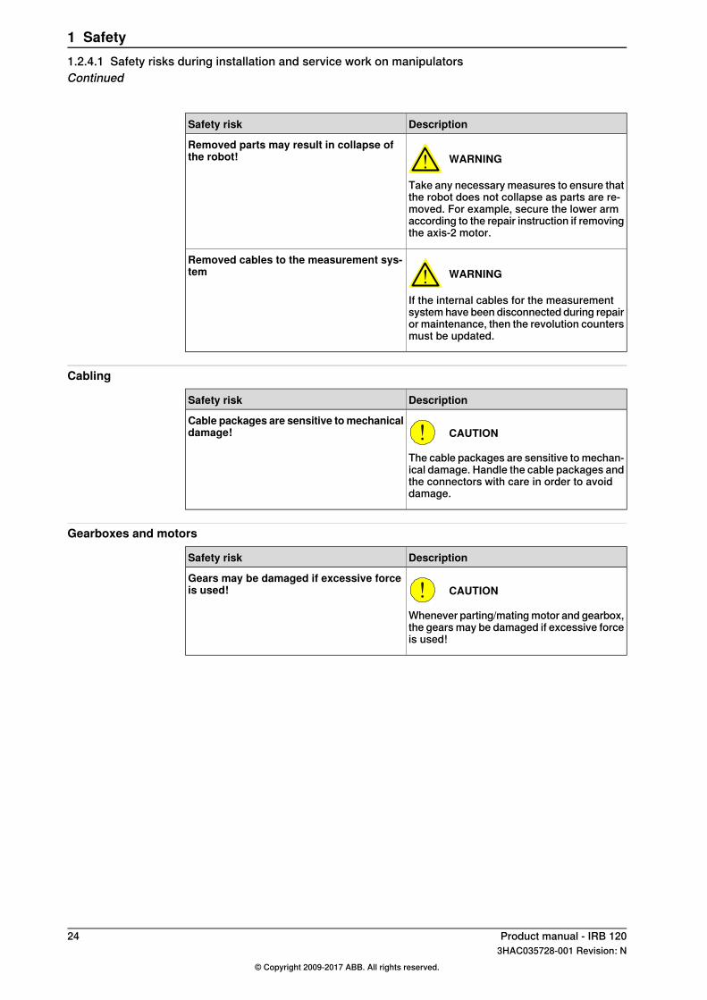
WARNING
Take any necessary measures to ensure thatthe robot does not collapse as parts are re-moved. For example, secure the lower armaccording to the repair instruction if removingthe axis-2 motor.
Removed parts may result in collapse ofthe robot!
WARNING
If the internal cables for the measurementsystem have been disconnected during repairor maintenance, then the revolution countersmust be updated.
Removed cables to the measurement sys-tem
Cabling
DescriptionSafety risk
CAUTION
The cable packages are sensitive to mechan-ical damage. Handle the cable packages andthe connectors with care in order to avoiddamage.
Cable packages are sensitive tomechanicaldamage!
Gearboxes and motors
DescriptionSafety risk
CAUTION
Whenever parting/mating motor and gearbox,the gears may be damaged if excessive forceis used!
Gears may be damaged if excessive forceis used!
24 Product manual - IRB 1203HAC035728-001 Revision: N
© Copyright 2009-2017 ABB. All rights reserved.
1 Safety1.2.4.1 Safety risks during installation and service work on manipulatorsContinued
1.2.4.2 CAUTION - Hot parts may cause burns!
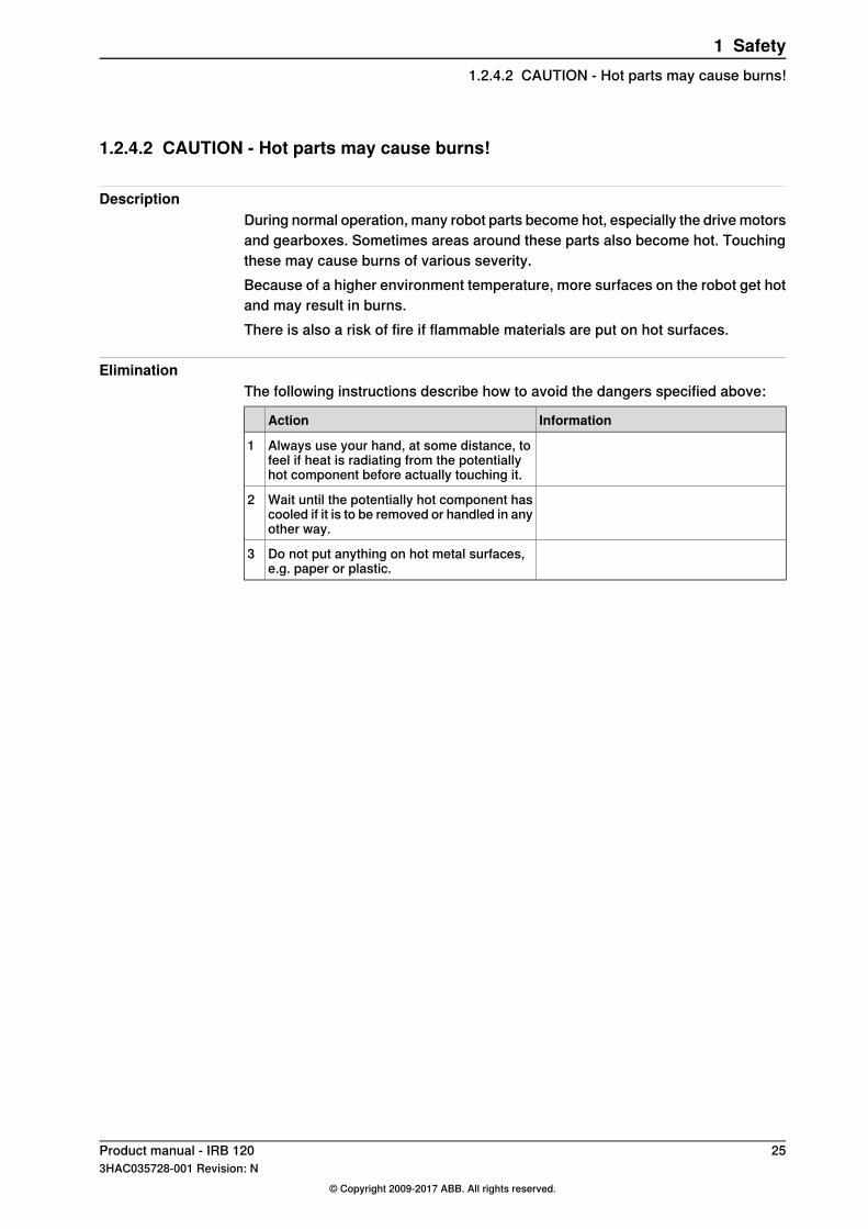
DescriptionDuring normal operation, many robot parts become hot, especially the drive motorsand gearboxes. Sometimes areas around these parts also become hot. Touchingthese may cause burns of various severity.Because of a higher environment temperature, more surfaces on the robot get hotand may result in burns.There is also a risk of fire if flammable materials are put on hot surfaces.
EliminationThe following instructions describe how to avoid the dangers specified above:
InformationAction
Always use your hand, at some distance, tofeel if heat is radiating from the potentiallyhot component before actually touching it.
1
Wait until the potentially hot component hascooled if it is to be removed or handled in anyother way.
2
Do not put anything on hot metal surfaces,e.g. paper or plastic.
3
Product manual - IRB 120 253HAC035728-001 Revision: N
© Copyright 2009-2017 ABB. All rights reserved.
1 Safety1.2.4.2 CAUTION - Hot parts may cause burns!
1.2.4.3 Safety risks related to tools/work pieces
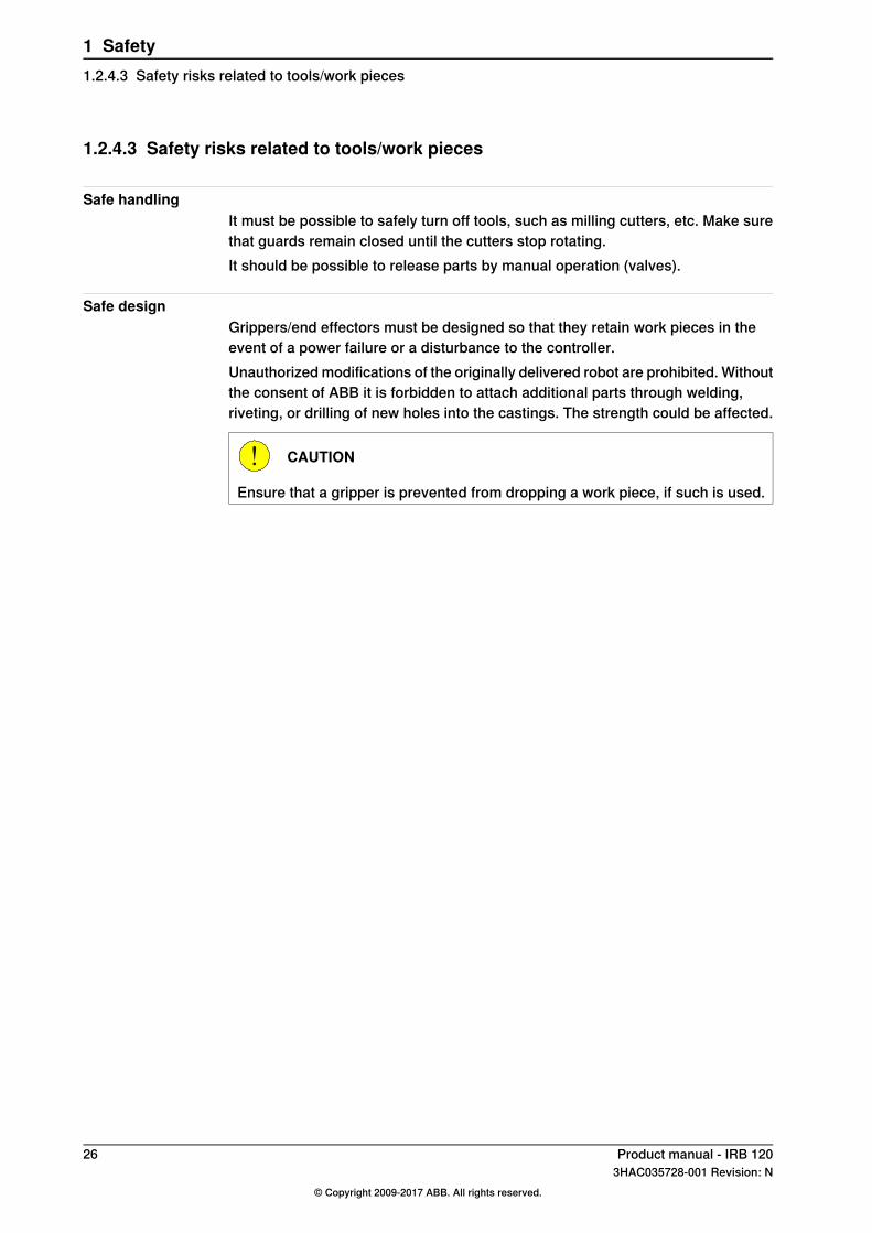
Safe handlingIt must be possible to safely turn off tools, such as milling cutters, etc. Make surethat guards remain closed until the cutters stop rotating.It should be possible to release parts by manual operation (valves).
Safe designGrippers/end effectors must be designed so that they retain work pieces in theevent of a power failure or a disturbance to the controller.Unauthorized modifications of the originally delivered robot are prohibited. Withoutthe consent of ABB it is forbidden to attach additional parts through welding,riveting, or drilling of new holes into the castings. The strength could be affected.
CAUTION
Ensure that a gripper is prevented from dropping a work piece, if such is used.
26 Product manual - IRB 1203HAC035728-001 Revision: N
© Copyright 2009-2017 ABB. All rights reserved.
1 Safety1.2.4.3 Safety risks related to tools/work pieces

1.2.4.4 Safety risks related to pneumatic/hydraulic systems
GeneralSpecial safety regulations apply to pneumatic and hydraulic systems.
Note
All components that remain pressurized after separating the machine from thepower supply must be provided with clearly visible drain facilities and a warningsign that indicates the need for pressure relief before adjustments or performingany maintenance on the robot system.
Residual energy• Residual energy can be present in these systems. After shutdown, particular
care must be taken.• The pressure must be released in the complete pneumatic or hydraulic
systems before starting to repair them.• Work on hydraulic equipment may only be performed by persons with special
knowledge and experience of hydraulics.• All pipes, hoses, and connections have to be inspected regularly for leaks
and damage. Damage must be repaired immediately.• Splashed oil may cause injury or fire.
Safe design• Gravity may cause any parts or objects held by these systems to drop.• Dump valves should be used in case of emergency.• Shot bolts should be used to prevent tools, etc., from falling due to gravity.
Product manual - IRB 120 273HAC035728-001 Revision: N
© Copyright 2009-2017 ABB. All rights reserved.
1 Safety1.2.4.4 Safety risks related to pneumatic/hydraulic systems

1.2.4.5 Safety risks during operational disturbances
General• The industrial robot is a flexible tool that can be used in many different
industrial applications.• All work must be carried out professionally and in accordance with the
applicable safety regulations.• Care must be taken at all times.
Qualified personnelCorrective maintenance must only be carried out by qualified personnel who arefamiliar with the entire installation as well as the special risks associated with itsdifferent parts.
Extraordinary risksIf the working process is interrupted, extra care must be taken due to risks otherthan those associated with regular operation. Such an interruption may have to berectified manually.
28 Product manual - IRB 1203HAC035728-001 Revision: N
© Copyright 2009-2017 ABB. All rights reserved.
1 Safety1.2.4.5 Safety risks during operational disturbances

1.2.4.6 Risks associated with live electric parts
Voltage related risks, generalWork on the electrical equipment of the robot must be performed by a qualifiedelectrician in accordance with electrical regulations.
• Although troubleshooting may, on occasion, need to be carried out while thepower supply is turned on, the robot must be turned off (by setting the mainswitch to OFF) when repairing faults, disconnecting electric leads anddisconnecting or connecting units.
• The main supply to the robot must be connected in such a way that it canbe turned off from outside the working space of the robot.
• Make sure that no one else can turn on the power to the controller and robotwhile you are working with the system. A good method is to always lock themain switch on the controller cabinet with a safety lock.
The necessary protection for the electrical equipment and robot system duringconstruction, commissioning, and maintenance is guaranteed if the valid regulationsare followed.All work must be performed:
• by qualified personnel• on machine/robot system in deadlock• in an isolated state, disconnected from power supply, and protected against
reconnection.
Voltage related risks, IRC5 controllerA danger of high voltage is associated with, for example, the following parts:
• Be aware of stored electrical energy (DC link, Ultracapacitor bank unit) inthe controller.
• Units such as I/O modules, can be supplied with power from an externalsource.
• The main supply/main switch• The transformers• The power unit• The control power supply (230 VAC)• The rectifier unit (262/400-480 VAC and 400/700 VDC. Note: capacitors!)• The drive unit (400/700 VDC)• The drive system power supply (230 VAC)• The service outlets (115/230 VAC)• The customer power supply (230 VAC)• The power supply unit for additional tools, or special power supply units for
the machining process.• The external voltage connected to the controller remains live even when the
robot is disconnected from the mains.• Additional connections.
Continues on next pageProduct manual - IRB 120 293HAC035728-001 Revision: N
© Copyright 2009-2017 ABB. All rights reserved.
1 Safety1.2.4.6 Risks associated with live electric parts
Voltage related risks, robotA danger of low voltage is associated with the robot in:
• The power supply for the motors (up to 800 VDC).• The user connections for tools or other parts of the installation (max. 230
VAC).
Voltage related risks, tools, material handling devices, etc.Tools, material handling devices, etc., may be live even if the robot system is inthe OFF position. Power supply cables which are in motion during the workingprocess may be damaged.
30 Product manual - IRB 1203HAC035728-001 Revision: N
© Copyright 2009-2017 ABB. All rights reserved.
1 Safety1.2.4.6 Risks associated with live electric partsContinued

1.2.5 Safety actions
1.2.5.1 Safety fence dimensions
GeneralInstall a safety cell around the robot to ensure safe robot installation and operation.
DimensioningThe fence or enclosure must be dimensioned to withstand the force created if theload being handled by the robot is dropped or released at maximum speed.Determine the maximum speed from the maximum velocities of the robot axes andfrom the position at which the robot is working in the work cell (see the sectionRobot motion in the Product specification).Also consider the maximum possible impact caused by a breaking or malfunctioningrotating tool or other device fitted to the robot.
Product manual - IRB 120 313HAC035728-001 Revision: N
© Copyright 2009-2017 ABB. All rights reserved.
1 Safety1.2.5.1 Safety fence dimensions

1.2.5.2 Fire extinguishing
Note
Use a CARBON DIOXIDE (CO2) extinguisher in the event of a fire in the robot orcontroller!
32 Product manual - IRB 1203HAC035728-001 Revision: N
© Copyright 2009-2017 ABB. All rights reserved.
1 Safety1.2.5.2 Fire extinguishing
1.2.5.3 Emergency release of the robot arm
DescriptionIn an emergency situation, the brakes on a robot axis can be released manuallyby pushing a brake release button.How to release the brakes is detailed in the section:
• Manually releasing the brakes on page 66.The robot arm may be moved manually on smaller robot models, but larger modelsmay require using an overhead crane or similar equipment.
Increased injuryBefore releasing the brakes, make sure that the weight of the arms does notincrease the pressure on the trapped person, further increasing any injury!
DANGER
When releasing the holding brakes, the robot axes may move very quickly andsometimes in unexpected ways.Make sure no personnel is near or beneath the robot arm.
Product manual - IRB 120 333HAC035728-001 Revision: N
© Copyright 2009-2017 ABB. All rights reserved.
1 Safety1.2.5.3 Emergency release of the robot arm

1.2.5.4 Brake testing
When to testDuring operation, the holding brake of each axis normally wears down. A test canbe performed to determine whether the brake can still perform its function.
How to testThe function of the holding brake of each axis motor may be verified as describedbelow:
1 Run each robot axis to a position where the combined weight of the robotarm and any load is maximized (maximum static load).
2 Switch the motor to the MOTORS OFF.3 Inspect and verify that the axis maintains its position.
If the robot does not change position as the motors are switched off, thenthe brake function is adequate.
34 Product manual - IRB 1203HAC035728-001 Revision: N
© Copyright 2009-2017 ABB. All rights reserved.
1 Safety1.2.5.4 Brake testing

1.2.5.5 Risk of disabling function "Reduced speed 250 mm/s"
Note
Do not change Transm gear ratio or other kinematic system parameters fromthe FlexPendant or a PC. This will affect the safety function "Reduced speed 250mm/s".
Product manual - IRB 120 353HAC035728-001 Revision: N
© Copyright 2009-2017 ABB. All rights reserved.
1 Safety1.2.5.5 Risk of disabling function "Reduced speed 250 mm/s"

1.2.5.6 Enabling device and hold-to-run functionality
Three-position enabling deviceThe three-position enabling device is a manually operated, constant pressurepush-button which, when continuously activated in one position only, allowspotentially hazardous functions but does not initiate them. In any other position,hazardous functions are stopped safely.The three-position enabling device is of a specific type where you must press thepush-button only half-way to activate it. In the fully in and fully out positions,operating the robot is impossible.
Note
The three-position enabling device is a push-button located on the teach pendantwhich, when pressed halfway in, switches the system to MOTORS ON. Whenthe enabling device is released or pushed all the way in, the manipulator switchesto the MOTORS OFF state.To ensure safe use of the teach pendant, the following must be implemented:
• The enabling device must never be rendered inoperational in any way.• During programming and testing, the enabling device must be released as
soon as there is no need for the robot to move.• Anyone entering the working space of the robot must always hold the teach
pendant. This is to prevent anyone else from taking control of the robotwithout his/her knowledge.
Hold-to-run functionThe hold-to-run function allows movement when a button connected to the functionis actuated manually and immediately stops any movement when released. Thehold-to-run function can only be used in manual mode.How to operate the hold-to-run function for IRC5 is described in Operatingmanual - IRC5 with FlexPendant.
36 Product manual - IRB 1203HAC035728-001 Revision: N
© Copyright 2009-2017 ABB. All rights reserved.
1 Safety1.2.5.6 Enabling device and hold-to-run functionality

1.2.5.7 Work inside the working range of the robot
WARNING
If work must be carried out within the work area of the robot, then the followingpoints must be observed:
• The operating mode selector on the controller must be in the manual modeposition to render the three-position enabling device operational and to blockoperation from a computer link or remote control panel.
• The maximum speed of the robot is limited to 250 mm/s when the operatingmode selector is in the position Manual mode with reduced speed. Thisshould be the normal position when entering the working space.The position Manual mode with full speed (100%) may only be used bytrained personnel who are aware of the risks that this entails. Manual modewith full speed (100%) is not available in USA or Canada.
• Pay attention to the rotating axes of the robot. Keep away from axes to notget entangled with hair or clothing. Also, be aware of any danger that maybe caused by rotating tools or other devices mounted on the robot or insidethe cell.
• Test the motor brake on each axis, according to the section Brake testingon page 34.
• To prevent anyone else from taking control of the robot, always put a safetylock on the cell door and bring the three-position enabling device with youwhen entering the working space.
WARNING
NEVER, under any circumstances, stay beneath any of the robot's axes! Thereis always a risk that the robot will move unexpectedly when robot axes are movedusing the three-position enabling device or during other work inside the workingrange of the robot.
Product manual - IRB 120 373HAC035728-001 Revision: N
© Copyright 2009-2017 ABB. All rights reserved.
1 Safety1.2.5.7 Work inside the working range of the robot

1.3 Safety signals and symbols
1.3.1 Safety signals in the manual
Introduction to safety signalsThis section specifies all dangers that can arise when doing the work describedin the user manuals. Each danger consists of:
• A caption specifying the danger level (DANGER, WARNING, or CAUTION)and the type of danger.
• A brief description of what will happen if the operator/service personnel donot eliminate the danger.
• Instruction about how to eliminate danger to simplify doing the work.
Danger levelsThe table below defines the captions specifying the danger levels used throughoutthis manual.
SignificanceDesignationSymbol
Warns that an accident will occur if the instructionsare not followed, resulting in a serious or fatal injuryand/or severe damage to the product. It applies towarnings that apply to danger with, for example,contact with high voltage electrical units, explosionor fire risk, risk of poisonous gases, risk of crushing,impact, fall from height, and so on.
DANGER
xx0200000022
Warns that an accident may occur if the instructionsare not followed that can lead to serious injury, pos-sibly fatal, and/or great damage to the product. Itapplies to warnings that apply to danger with, forexample, contact with high voltage electrical units,explosion or fire risk, risk of poisonous gases, riskof crushing, impact, fall from height, etc.
WARNING
xx0100000002
Warns for electrical hazards which could result insevere personal injury or death.
ELECTRICALSHOCK
xx0200000024
Warns that an accident may occur if the instructionsare not followed that can result in injury and/ordamage to the product. It also applies to warningsof risks that include burns, eye injury, skin injury,hearing damage, crushing or slipping, tripping, im-pact, fall from height, etc. Furthermore, it applies towarnings that include function requirements whenfitting and removing equipment where there is a riskof damaging the product or causing a breakdown.
CAUTION
xx0100000003
Warns for electrostatic hazards which could resultin severe damage to the product.
ELECTROSTATICDISCHARGE (ESD)
xx0200000023
Continues on next page38 Product manual - IRB 120
3HAC035728-001 Revision: N© Copyright 2009-2017 ABB. All rights reserved.
1 Safety1.3.1 Safety signals in the manual
SignificanceDesignationSymbol
Describes important facts and conditions.NOTE
xx0100000004
Describes where to find additional information orhow to do an operation in an easier way.
TIP
xx0100000098
Product manual - IRB 120 393HAC035728-001 Revision: N
© Copyright 2009-2017 ABB. All rights reserved.
1 Safety1.3.1 Safety signals in the manual
Continued

1.3.2 Safety symbols on product labels
Introduction to labelsThis section describes safety symbols used on labels (stickers) on the product.Symbols are used in combinations on the labels, describing each specific warning.The descriptions in this section are generic, the labels can contain additionalinformation such as values.
Note
The safety and health symbols on the labels on the product must be observed.Additional safety information given by the system builder or integrator must alsobe observed.
Types of labelsBoth the manipulator and the controller are marked with several safety andinformation labels, containing important information about the product. Theinformation is useful for all personnel handling the robot, for example duringinstallation, service, or operation.The safety labels are language independent, they only use graphics. See Symbolson safety labels on page 40.The information labels can contain information in text (English, German, andFrench).
Symbols on safety labels
DescriptionSymbol
Warning!
xx0900000812
Warns that an accident may occur if the instructions are notfollowed that can lead to serious injury, possibly fatal, and/orgreat damage to the product. It applies to warnings that applyto danger with, for example, contact with high voltage electricalunits, explosion or fire risk, risk of poisonous gases, risk ofcrushing, impact, fall from height, etc.
Caution!
xx0900000811
Warns that an accident may occur if the instructions are notfollowed that can result in injury and/or damage to the product.It also applies to warnings of risks that include burns, eye injury,skin injury, hearing damage, crushing or slipping, tripping, im-pact, fall from height, etc. Furthermore, it applies to warningsthat include function requirements when fitting and removingequipment where there is a risk of damaging the product orcausing a breakdown.
Prohibition
xx0900000839
Used in combinations with other symbols.
Continues on next page40 Product manual - IRB 120
3HAC035728-001 Revision: N© Copyright 2009-2017 ABB. All rights reserved.
1 Safety1.3.2 Safety symbols on product labels

DescriptionSymbol
See user documentation
xx0900000813
Read user documentation for details.Which manual to read is defined by the symbol:
• No text: Product manual.• EPS: Application manual - Electronic Position Switches.
Before disassemble, see product manual
xx0900000816
Do not disassemble
xx0900000815
Disassembling this part can cause injury.
Extended rotation
xx0900000814
This axis has extended rotation (working area) compared tostandard.
Brake release
xx0900000808
Pressing this button will release the brakes. This means thatthe robot arm can fall down.
Continues on next pageProduct manual - IRB 120 413HAC035728-001 Revision: N
© Copyright 2009-2017 ABB. All rights reserved.
1 Safety1.3.2 Safety symbols on product labels
Continued
DescriptionSymbol
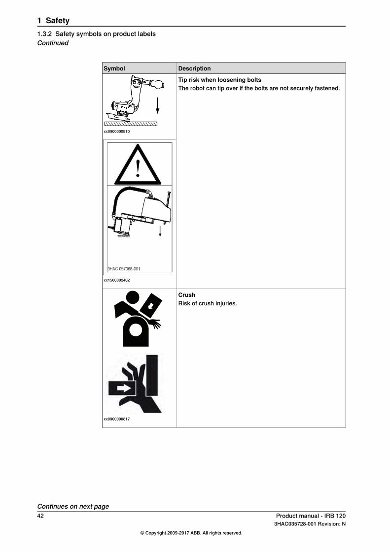
Tip risk when loosening bolts
xx0900000810
The robot can tip over if the bolts are not securely fastened.
xx1500002402
Crush
xx0900000817
Risk of crush injuries.
Continues on next page42 Product manual - IRB 120
3HAC035728-001 Revision: N© Copyright 2009-2017 ABB. All rights reserved.
1 Safety1.3.2 Safety symbols on product labelsContinued

DescriptionSymbol
Heat
xx0900000818
Risk of heat that can cause burns. (Both signs are used)
3H
AC
44
31
-1/0
6
!
xx1300001087
Moving robot
1
2
34
56
xx0900000819
The robot can move unexpectedly.
xx1000001141
1
2 3
4
xx1500002616
Continues on next pageProduct manual - IRB 120 433HAC035728-001 Revision: N
© Copyright 2009-2017 ABB. All rights reserved.
1 Safety1.3.2 Safety symbols on product labels
Continued

DescriptionSymbol
Brake release buttons
xx0900000820
xx1000001140
Lifting bolt
xx0900000821
Chain sling with shortener
xx1000001242
Lifting of robot
xx0900000822
Oil
xx0900000823
Can be used in combination with prohibition if oil is not allowed.
Mechanical stop
xx0900000824
Continues on next page44 Product manual - IRB 120
3HAC035728-001 Revision: N© Copyright 2009-2017 ABB. All rights reserved.
1 Safety1.3.2 Safety symbols on product labelsContinued

DescriptionSymbol
No mechanical stop
xx1000001144
Stored energy
xx0900000825
Warns that this part contains stored energy.Used in combination with Do not disassemble symbol.
Pressure
xx0900000826
Warns that this part is pressurized. Usually contains additionaltext with the pressure level.
Shut off with handle
xx0900000827
Use the power switch on the controller.
Do not step
xx1400002648
Warns that stepping on these parts can cause damage to theparts.
Product manual - IRB 120 453HAC035728-001 Revision: N
© Copyright 2009-2017 ABB. All rights reserved.
1 Safety1.3.2 Safety symbols on product labels
Continued
1.4 Safety related instructions
1.4.1 DANGER - Moving robots are potentially lethal!
DescriptionAny moving robot is a potentially lethal machine.When running, the robot may perform unexpected and sometimes irrationalmovements. Moreover, all movements are performed with great force and mayseriously injure any personnel and/or damage any piece of equipment locatedwithin the working range of the robot.
Elimination
NoteAction
Emergency stop equipment such as gates,tread mats, light curtains, etc.
Before attempting to run the robot, makesure all emergency stop equipment is cor-rectly installed and connected.
1
How to use the hold-to-run function is de-scribed in section How to use the hold-to-run function in theOperatingmanual - IRC5with FlexPendant.
Usually the hold-to-run function is activeonly in manual full speed mode. To in-crease safety it is also possible to activatehold-to-run for manual reduced speed witha system parameter.
2
The hold-to-run function is used in manualmode, not in automatic mode.
Make sure no personnel are present withinthe working range of the robot beforepressing the start button.
3
46 Product manual - IRB 1203HAC035728-001 Revision: N
© Copyright 2009-2017 ABB. All rights reserved.
1 Safety1.4.1 DANGER - Moving robots are potentially lethal!

1.4.2 DANGER - First test run may cause injury or damage!
DescriptionSince performing a service activity often requires disassembly of the robot, thereare several safety risks to take into consideration before the first test run.
EliminationFollow the procedure below when performing the first test run after a serviceactivity, such as repair, installation, or maintenance.
DANGER
Running the robot without fulfilling the following aspects, may cause severedamage to the robot.
Action
Remove all service tools and foreign objects from the robot and its working area.1
Verify that the robot is secured to its position, see installation section in the productmanual for the robot.
2
Verify that any safety equipment installed to secure the robot arm position or restrictthe robot arm motion during service activity is removed.
3
Verify that the fixture and work piece are well secured, if applicable.4
Install all safety equipment properly.5
Make sure all personnel are standing at a safe distance from the robot, that is out ofits reach behind safety fences, and so on.
6
Pay special attention to the function of the part that previously was serviced.7
Collision risks
CAUTION
When programming the movements of the robot, always identify potential collisionrisks before the first test run.
Product manual - IRB 120 473HAC035728-001 Revision: N
© Copyright 2009-2017 ABB. All rights reserved.
1 Safety1.4.2 DANGER - First test run may cause injury or damage!

1.4.3 DANGER - Make sure that the main power has been switched off!
DescriptionWorking with high voltage is potentially lethal. Persons subjected to high voltagemay suffer cardiac arrest, burn injuries, or other severe injuries. To avoid thesedangers, do not proceed working before eliminating the danger as detailed below.
Elimination, IRC5 Single Cabinet Controller
Note/illustrationAction
xx0600002782
Switch off the main switch on the controllercabinet.
1
A: Main switch
Elimination, IRC5 Dual Cabinet Controller
Note/illustrationAction
xx0600002783
Switch off the main switch on the DriveModule.
1
K: Main switch, Drive Module
A: Main switch, Control ModuleSwitch off the main switch on the ControlModule.
2
Continues on next page48 Product manual - IRB 120
3HAC035728-001 Revision: N© Copyright 2009-2017 ABB. All rights reserved.
1 Safety1.4.3 DANGER - Make sure that the main power has been switched off!

Elimination, IRC5 Compact Controller
Note/illustrationAction
Note that the position of the main switch can vary depend-ing on the year model.
A
xx0900000313
Switch off the main powerswitch on the controllercabinet.
1
A: Main power switch
Disconnect the input powercable from the wall socket.
2
Product manual - IRB 120 493HAC035728-001 Revision: N
© Copyright 2009-2017 ABB. All rights reserved.
1 Safety1.4.3 DANGER - Make sure that the main power has been switched off!
Continued

1.4.4 WARNING - The unit is sensitive to ESD!
DescriptionESD (electrostatic discharge) is the transfer of electrical static charge between twobodies at different potentials, either through direct contact or through an inducedelectrical field. When handling parts or their containers, personnel not groundedmay potentially transfer high static charges. This discharge may destroy sensitiveelectronics.
Elimination
NoteAction
Wrist straps must be tested frequently to ensurethat they are not damaged and are operating cor-rectly.
Use a wrist strap.1
The mat must be grounded through a current-limit-ing resistor.
Use an ESD protective floor mat.2
The mat should provide a controlled discharge ofstatic voltages and must be grounded.
Use a dissipative table mat.3
Location of wrist strap buttonThe location of the wrist strap button is shown in the following illustration.
IRC5
A
xx1300000856
Wrist strap buttonA
Continues on next page50 Product manual - IRB 120
3HAC035728-001 Revision: N© Copyright 2009-2017 ABB. All rights reserved.
1 Safety1.4.4 WARNING - The unit is sensitive to ESD!

IRC5 Compact Controller
A
xx1400001622
Wrist strap buttonA
Product manual - IRB 120 513HAC035728-001 Revision: N
© Copyright 2009-2017 ABB. All rights reserved.
1 Safety1.4.4 WARNING - The unit is sensitive to ESD!
Continued
1.4.5 WARNING - Safety risks during handling of batteries
DescriptionUnder normal conditions of use, the electrode materials and liquid electrolyte inthe batteries are not exposed to the outside, provided the battery integrity ismaintained and seals remain intact.There is a risk of exposure only in case of abuse (mechanical, thermal, electrical)which leads to the activation of safety valves and/or the rupture of the batterycontainer. Electrolyte leakage, electrode materials reaction with moisture/water orbattery vent/explosion/fire may follow, depending upon the circumstances.
Note
Appropriate disposal regulations must be observed.
Elimination
NoteAction
Operating temperaturesare listed in Pre-install-ation procedure onpage 56.
Do not short circuit, recharge, puncture, incinerate, crush,immerse, force discharge or expose to temperatures abovethe declared operating temperature range of the product.Risk of fire or explosion.
1
Use safety glasses when handling the batteries.2
In the event of leakage, wear rubber gloves and chemicalapron.
3
In the event of fire, use self-contained breathing apparatus.4
52 Product manual - IRB 1203HAC035728-001 Revision: N
© Copyright 2009-2017 ABB. All rights reserved.
1 Safety1.4.5 WARNING - Safety risks during handling of batteries
1.4.6 WARNING - Safety risks during work with gearbox lubricants (oil or grease)
DescriptionWhen handling gearbox lubricants, there is a risk of both personal injury andproduct damage occurring. The following safety information must be regardedbefore performing any work with lubricants in the gearboxes.
Note
When handling oil, grease, or other chemical substances the safety informationof the manufacturer must be observed.
Note
When aggressive media is handled, an appropriate skin protection must beprovided. Gloves and goggles are recommended.
Note
Appropriate disposal regulations must be observed.
Note
Take special care when handling hot lubricants.
Warnings and elimination
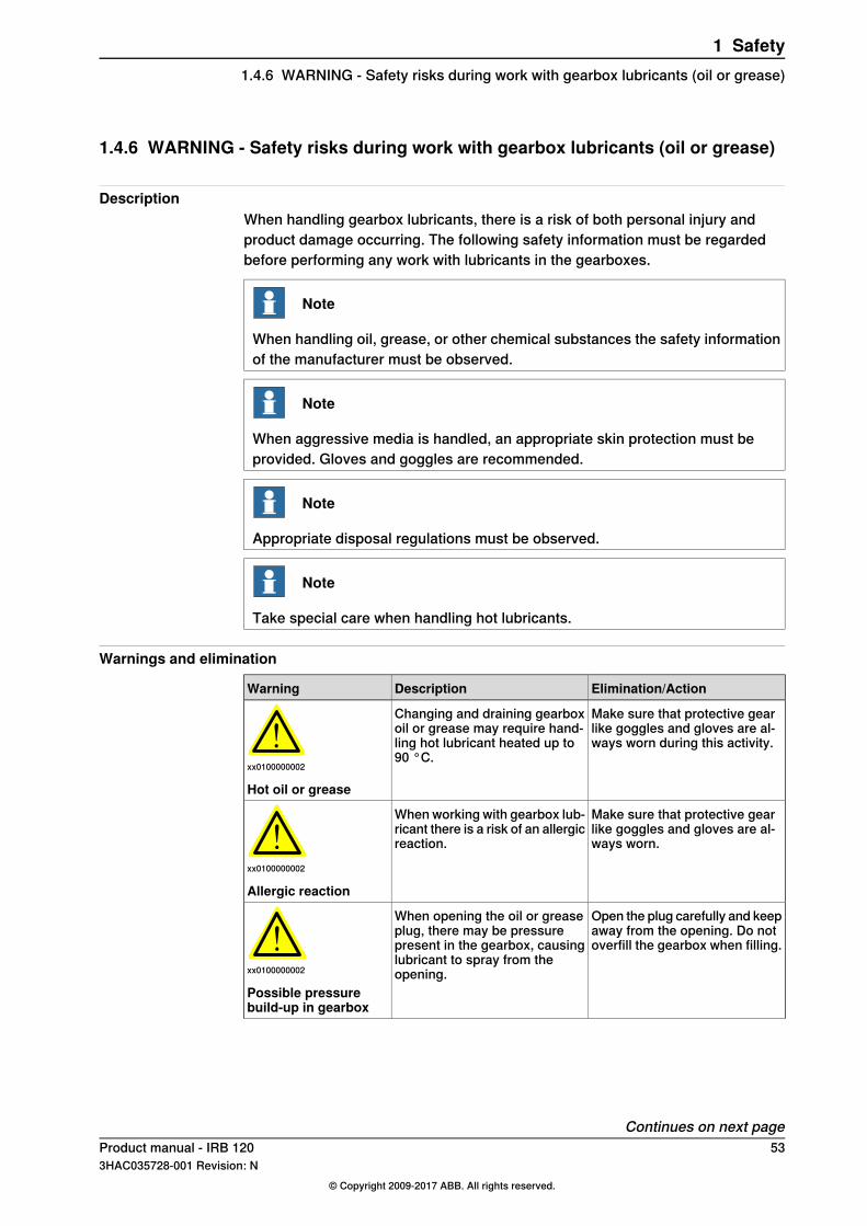
Elimination/ActionDescriptionWarning
Make sure that protective gearlike goggles and gloves are al-ways worn during this activity.
Changing and draining gearboxoil or grease may require hand-ling hot lubricant heated up to90 °C.
xx0100000002
Hot oil or grease
Make sure that protective gearlike goggles and gloves are al-ways worn.
When working with gearbox lub-ricant there is a risk of an allergicreaction.
xx0100000002
Allergic reaction
Open the plug carefully and keepaway from the opening. Do notoverfill the gearbox when filling.
When opening the oil or greaseplug, there may be pressurepresent in the gearbox, causinglubricant to spray from theopening.xx0100000002
Possible pressurebuild-up in gearbox
Continues on next pageProduct manual - IRB 120 533HAC035728-001 Revision: N
© Copyright 2009-2017 ABB. All rights reserved.
1 Safety1.4.6 WARNING - Safety risks during work with gearbox lubricants (oil or grease)
Elimination/ActionDescriptionWarning
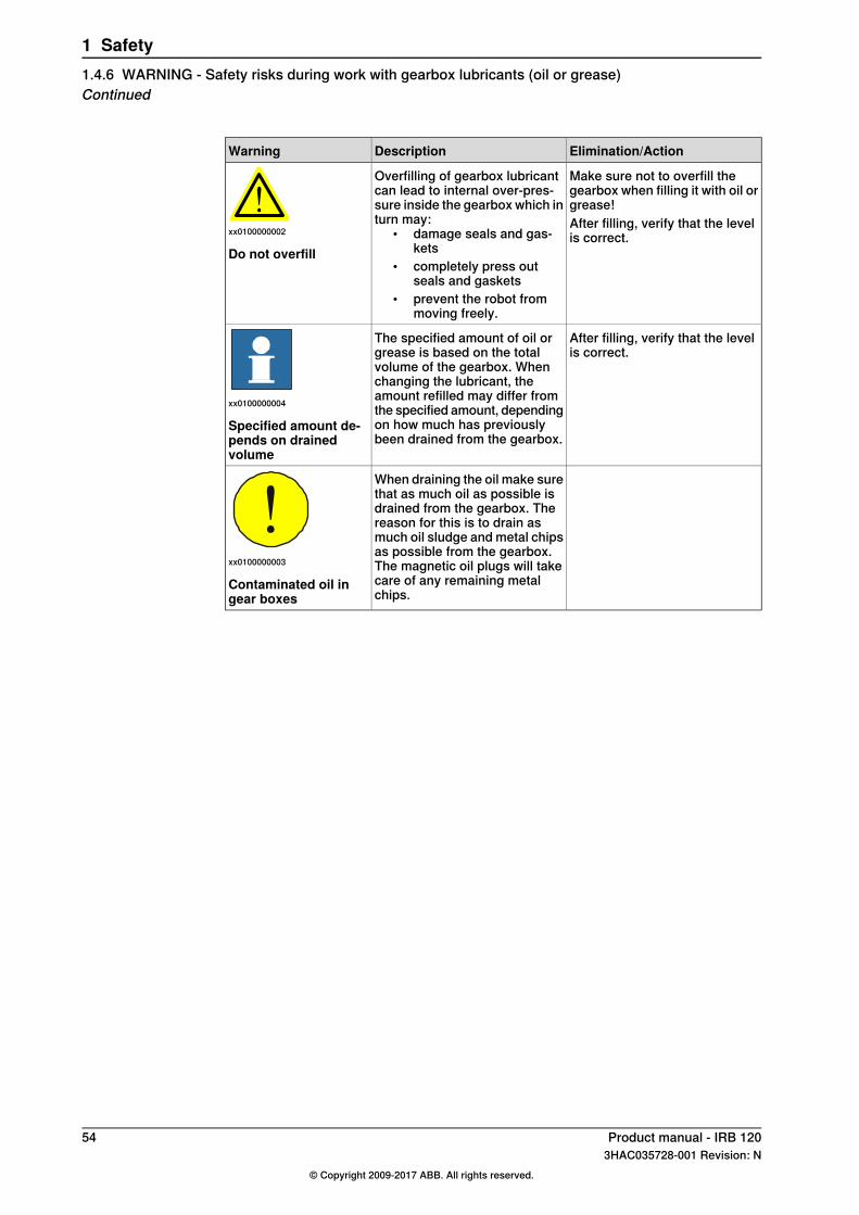
Make sure not to overfill thegearbox when filling it with oil orgrease!
Overfilling of gearbox lubricantcan lead to internal over-pres-sure inside the gearbox which inturn may:
• damage seals and gas-kets
• completely press outseals and gaskets
• prevent the robot frommoving freely.
xx0100000002
Do not overfill
After filling, verify that the levelis correct.
After filling, verify that the levelis correct.
The specified amount of oil orgrease is based on the totalvolume of the gearbox. Whenchanging the lubricant, theamount refilled may differ fromthe specified amount, dependingon how much has previouslybeen drained from the gearbox.
xx0100000004
Specified amount de-pends on drainedvolume
When draining the oil make surethat as much oil as possible isdrained from the gearbox. Thereason for this is to drain asmuch oil sludge and metal chipsas possible from the gearbox.The magnetic oil plugs will takecare of any remaining metalchips.
xx0100000003
Contaminated oil ingear boxes
54 Product manual - IRB 1203HAC035728-001 Revision: N
© Copyright 2009-2017 ABB. All rights reserved.
1 Safety1.4.6 WARNING - Safety risks during work with gearbox lubricants (oil or grease)Continued
2 Installation and commissioning2.1 Introduction
GeneralThis chapter contains assembly instructions and information for installing the IRB120 at the working site.More detailed technical data can be found in the Product specification for the IRB120, such as:
• Load diagram• Permitted extra loads (equipment), if any• Location of extra loads (equipment), if any.
Safety informationBefore any installation work is commenced, it is extremely important that all safetyinformation is observed!There are general safety aspects that must be read through, as well as more specificsafety information that describes the danger and safety risks when performing theprocedures. Read the chapterSafety on page17 before performing any installationwork.
Note
If the IRB 120 is connected to power, always make sure that the robot isconnected to protective earth before starting any installation work!For more information see:
• Product manual - IRC5
Product manual - IRB 120 553HAC035728-001 Revision: N
© Copyright 2009-2017 ABB. All rights reserved.
2 Installation and commissioning2.1 Introduction
2.2 Unpacking
2.2.1 Pre-installation procedure
IntroductionThis section is intended for use when unpacking and installing the robot for thefirst time. It also contains information useful during later re-installation of the robot.
Prerequisites for installation personnelInstallation personnel working with an ABB product must:
• be trained by ABB and have the required knowledge of mechanical andelectrical installation/maintenance/repair work
• conform to all national and local codes.
Checking the pre-requisites for installation
Action
Make a visual inspection of the packaging and make sure that nothing is damaged.1
Remove the packaging.2
Check for any visible transport damage.
Note
Stop unpacking and contact ABB if transport damages are found.
3
Clean the unit with a lint-free cloth, if necessary.4
Make sure that the lifting accessory used (if required) is suitable to handle the weightof the robot as specified in: Weight, robot on page 56
5
If the robot is not installed directly, it must be stored as described in: Storage condi-tions, robot on page 58
6
Make sure that the expected operating environment of the robot conforms to thespecifications as described in: Operating conditions, robot on page 59
7
Before taking the robot to its installation site, make sure that the site conforms to:• Loads on foundation, robot on page 57• Protection classes, robot on page 59• Requirements, foundation on page 58
8
Before moving the robot, please observe the stability of the robot: Risk of tipping/sta-bility on page 62
9
When these prerequisites are met, the robot can be taken to its installation site asdescribed in section: On-site installation on page 63
10
Install required equipment, if any.11
Weight, robotThe table shows the weight of the robot.
WeightRobot model
25 kgIRB 120
Continues on next page56 Product manual - IRB 120
3HAC035728-001 Revision: N© Copyright 2009-2017 ABB. All rights reserved.
2 Installation and commissioning2.2.1 Pre-installation procedure

Note
The weight does not include tools and other equipment fitted on the robot!
Loads on foundation, robotThe illustration shows the directions of the robots stress forces.The directions are valid for all floor mounted, suspended and inverted robots.
xy
xy
z
z
T
F
F
T
xx1100000521
Force in any direction in the XY planeFxy
Force in the Z planeFz
Bending torque in any direction in the XY planeTxy
Bending torque in the Z planeTz
The table shows the various forces and torques working on the robot during differentkinds of operation.
Note
These forces and torques are extreme values that are rarely encountered duringoperation. The values also never reach their maximum at the same time!
Floor mounted
Max. load (emergency stop)Endurance load (in operation)Force
±515 N±265 NForce xy
-265 ±365 N-265 ±200 NForce z
±400 Nm±195 NmTorque xy
±155 Nm±85 NmTorque z
Continues on next pageProduct manual - IRB 120 573HAC035728-001 Revision: N
© Copyright 2009-2017 ABB. All rights reserved.
2 Installation and commissioning2.2.1 Pre-installation procedure
Continued

Wall mounted
Max. load (emergency stop)Endurance load (in operation)Force
±735 N±470 NForce xy
0 ±630 N0 ±200 NForce z
±450 Nm±240 NmTorque xy
±175 Nm±90 NmTorque z
Suspended
Max. load (emergency stop)Endurance load (in operation)Force
±515 N±265 NForce xy
265 ±365 N265 ±200 NForce z
±400 Nm±195 NmTorque xy
±155 Nm±85 NmTorque z
Requirements, foundationThe table shows the requirements for the foundation where the weight of theinstalled robot is included:
NoteValueRequirement
Flat foundations give better repeatability of theresolver calibration compared to original settingson delivery from ABB.
0.1/500 mmFlatness of foundationsurface
The value for levelness aims at the circumstanceof the anchoring points in the robot base.
5°Maximum tilt
The value is recommended for optimal perform-ance.
22 Hz
Note
It may affect themanipulator life-time to have alower resonancefrequency thanrecommended.
Minimum resonancefrequency
Due to foundation stiffness, consider robot massincluding equipment. i
For information about compensating for founda-tion flexibility, see Application manual - Control-ler software IRC5, sectionMotion ProcessMode.
i The minimum resonance frequency given should be interpreted as the frequency of the robotmass/inertia, robot assumed stiff, when a foundation translational/torsional elasticity is added, i.e.,the stiffness of the pedestal where the robot is mounted. The minimum resonance frequency shouldnot be interpreted as the resonance frequency of the building, floor etc. For example, if the equivalentmass of the floor is very high, it will not affect robot movement, even if the frequency is well belowthe stated 25 Hz. The robot should be mounted as rigid as possibly to the floor.Disturbances from other machinery will affect the robot and the tool accuracy. The robot hasresonance frequencies in the region 10 – 20 Hz and disturbances in this region will be amplified,although somewhat damped by the servo control. This might be a problem, depending on therequirements from the applications. If this is a problem, the robot needs to be isolated from theenvironment.
Storage conditions, robotThe table shows the allowed storage conditions for the robot:
ValueParameter
-25° CMinimum ambient temperature
Continues on next page58 Product manual - IRB 120
3HAC035728-001 Revision: N© Copyright 2009-2017 ABB. All rights reserved.
2 Installation and commissioning2.2.1 Pre-installation procedureContinued

ValueParameter
+55° CMaximum ambient temperature
+70° CMaximum ambient temperature (less than 24 hrs)
95% at constant temperature(gaseous only)
Maximum ambient humidity
Operating conditions, robotThe table shows the allowed operating conditions for the robot:
ValueParameter
+5ºC iMinimum ambient temperature
+45ºCMaximum ambient temperature
+35ºC iiMaximum ambient temperature for robots with food gradelubrication
Max 95% at constant temperatureMaximum ambient humidityi At low environmental temperature < 10ºC is, as with any other machine, a warm-up phase
recommended to be run with the robot. Otherwise there is a risk that the robot stops or run withlower performance due to temperature dependent oil and grease viscosity.
ii For robots with food grade lubrication, if environment temperature > 35ºC, contact ABB for furtherinformation.
Protection classes, robotThe table shows the available protection types of the robot, with the correspondingprotection class.
Protection classProtection type
IP 30Manipulator, protection type Standard
IP 30Manipulator, protection type Clean Room
Product manual - IRB 120 593HAC035728-001 Revision: N
© Copyright 2009-2017 ABB. All rights reserved.
2 Installation and commissioning2.2.1 Pre-installation procedure
Continued

2.2.2 Working range and type of motion
Working rangeThe figures show the working ranges of the robot.The extreme positions of the robot arm are specified at the wrist center (dimensionsin mm).
Working rangeThe illustration shows the unrestricted working range of the robot.
580 580
11
2
98
2
R 556,1
X
Pos 1
Pos 0
Pos 7
Pos 8
Pos 3
Pos 4
Pos 2
Pos 6
Pos 5
Z
xx0900000263
Angle (degrees)Position at wrist center (mm)Posi-tion
Axis 3Axis 2ZX
0°0°630 mm302 mmA
-77°0°870 mm0 mmB
+70°0°300 mm169 mmC
-77°+90°270 mm580 mmD
-77°+110°91 mm545 mmE
-110°-110°-50 mm-440 mmF
+70°-110°445 mm-67 mmG
-77°-90°270 mm-580 mmH
-77°-110°91 mm-545 mmJ
Continues on next page60 Product manual - IRB 120
3HAC035728-001 Revision: N© Copyright 2009-2017 ABB. All rights reserved.
2 Installation and commissioning2.2.2 Working range and type of motion

Turning radiusThe turning radius of robot is shown in the figure.
A B
C
165°
165°
xx0900000157
Pos. CPos. BPos. ARobot variant
R169.4R580R121 iIRB 120-3/0.6i Minimum turning radius axis 1.
Robot motionThe table specifies the types and ranges of motion in every axes.
Range of movementType of motionLocation of motion
+165° to -165°Rotation motionAxis 1
+110° to -110°Arm motionAxis 2
+70° to -110°Arm motionAxis 3
+160° to -160°Wrist motionAxis 4
+120° to -120°Bend motionAxis 5
+400° to -400° (default)Turn motionAxis 6+242 revolutions to -242 re-volutions maximum i
i The default working range for axis 6 can be extended by changing parameter values in the software.Option 610-1 Independent axis can be used for resetting the revolution counter after the axis hasbeen rotated (no need for "rewinding" the axis).
Product manual - IRB 120 613HAC035728-001 Revision: N
© Copyright 2009-2017 ABB. All rights reserved.
2 Installation and commissioning2.2.2 Working range and type of motion
Continued
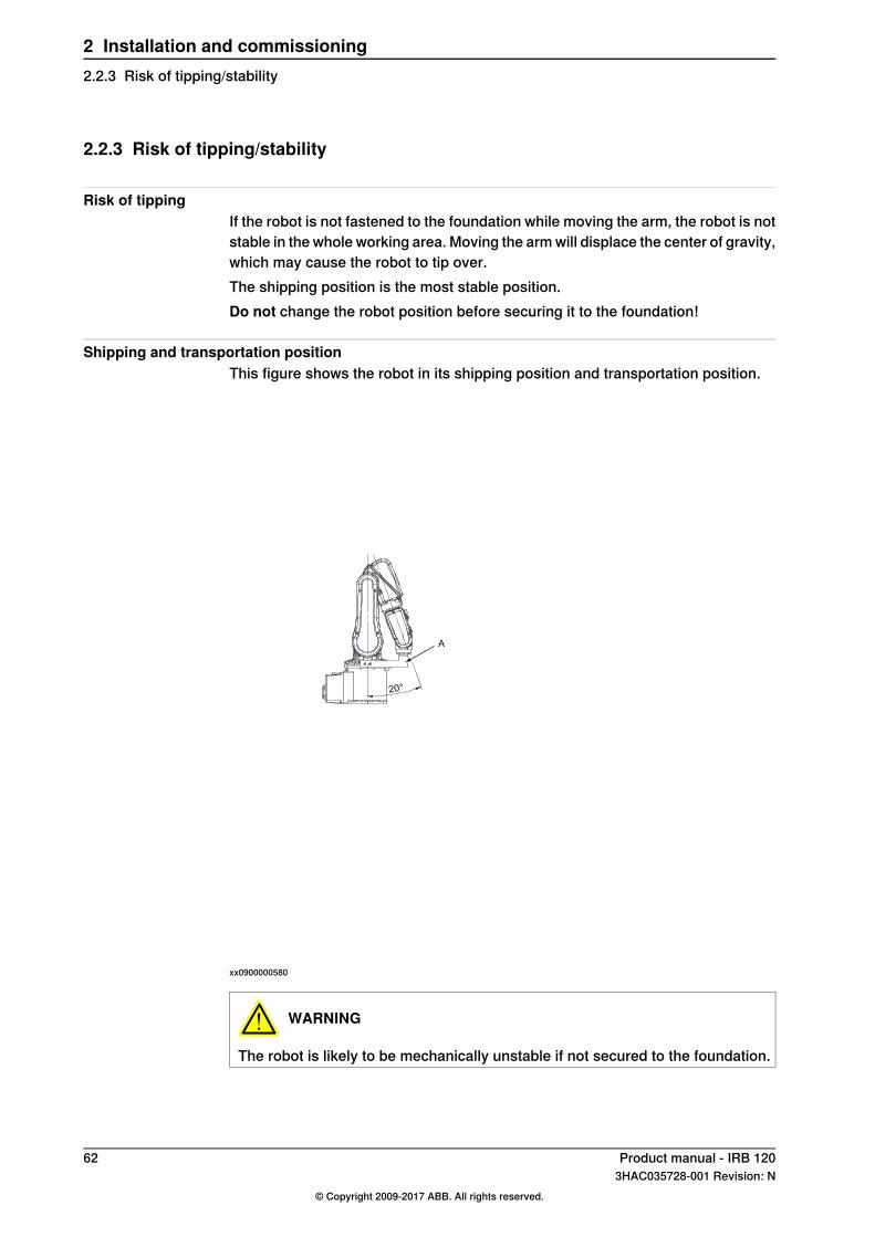
2.2.3 Risk of tipping/stability
Risk of tippingIf the robot is not fastened to the foundation while moving the arm, the robot is notstable in the whole working area. Moving the arm will displace the center of gravity,which may cause the robot to tip over.The shipping position is the most stable position.Do not change the robot position before securing it to the foundation!
Shipping and transportation positionThis figure shows the robot in its shipping position and transportation position.
20°
A
xx0900000580
WARNING
The robot is likely to be mechanically unstable if not secured to the foundation.
62 Product manual - IRB 1203HAC035728-001 Revision: N
© Copyright 2009-2017 ABB. All rights reserved.
2 Installation and commissioning2.2.3 Risk of tipping/stability

2.3 On-site installation
2.3.1 Lifting the robot with roundslings
IntroductionThis procedure details how to lift the robot using roundslings.
Required equipment
NoteEquipment
-Overhead crane
(Circle) Length: 3 mRoundslingsLifting capacity: 100 kg
The set includes:• bracket• attachment screws• washers.
For art. no. and details see chapter Referenceinformation section:
• Special tools on page 261
Lifting tool, set
LiftingAttach the roundslings as shown in the figure.
CAUTION
Use a thick cloth between round sling and robot where robot surface directlycontact with round sling.
Continues on next pageProduct manual - IRB 120 633HAC035728-001 Revision: N
© Copyright 2009-2017 ABB. All rights reserved.
2 Installation and commissioning2.3.1 Lifting the robot with roundslings
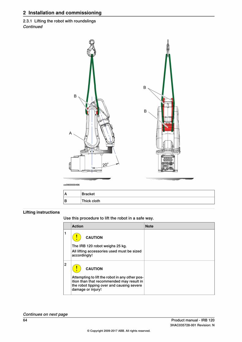
20°
A
B
B
B
xx0900000496
BracketA
Thick clothB
Lifting instructionsUse this procedure to lift the robot in a safe way.
NoteAction
CAUTION
The IRB 120 robot weighs 25 kg.All lifting accessories used must be sizedaccordingly!
1
CAUTION
Attempting to lift the robot in any other pos-ition than that recommended may result inthe robot tipping over and causing severedamage or injury!
2
Continues on next page64 Product manual - IRB 120
3HAC035728-001 Revision: N© Copyright 2009-2017 ABB. All rights reserved.
2 Installation and commissioning2.3.1 Lifting the robot with roundslingsContinued

NoteAction
WARNING
Personnel must not, under any circum-stances, be present under the suspendedload!
3
Detailed in section:• Risk of tipping/stability on page 62
Move the robot to its most stable position.4
DANGER
Turn off all electric power, hydraulic andpneumatic pressure supplies to the robot!
5
See Required equipment on page 63.
A CB D
E
xx0900000636
Fit the bracket with its attachment screwsand washers, in order to secure the upperarm to the base.
6
Parts:• A: Attachment screws M4x10 qual-
ity steel 8.8 ELZN (2 pcs)• B: Base• C: Bracket• D: Attachment screws M5x12 qual-
ity 8.8-A2F (2 pcs)• E: Upper arm
See the figure in:• Lifting on page 63
Attach the roundsling.7
Lift the robot with an overhead crane.8
Product manual - IRB 120 653HAC035728-001 Revision: N
© Copyright 2009-2017 ABB. All rights reserved.
2 Installation and commissioning2.3.1 Lifting the robot with roundslings
Continued
2.3.2 Manually releasing the brakes
Introduction to manually releasing the brakesThis section describes how to release the holding brakes for the motors of eachaxis.This can be done in three ways:
• using the brake release unit (placed on the front of the IRC5 Compactcontroller) when the robot is connected to the controller. For other controllervariants, the placing depends on the design of the cell.
• using the brake release unit when the robot is disconnected from thecontroller, but connected to an external power supply at the connector R1.MP.
• using an external voltage supply directly on the motor connector.
Note
On the single controller there is no brake release button. The customer orintegrator is responsible to ensure that it in case of emergency is possible torelease the brakes to move the manipulator axes without using motion power.
Continues on next page66 Product manual - IRB 120
3HAC035728-001 Revision: N© Copyright 2009-2017 ABB. All rights reserved.
2 Installation and commissioning2.3.2 Manually releasing the brakes

Brake release button at the front of IRC5 Compact controllerThe IRB 120 robot has no brake release button, instead use the brake releasebutton on the IRC5 Compact controller. For other controller variants, the placingdepends on the design of the cell.
xx0900000559
Brake release button (beneath the cover)A
Using the brake release unit when the robot is connected to the controllerUse this procedure to release the holding brakes using the internal brake releaseunit in the controller cabinet.
NoteAction
See the figure in:• Brake release button at the front of
IRC5 Compact controller onpage 67
The brake release button is located on thefront of the IRC5 Compact controller.
Note
The single brake release button, is used torelease the brakes on all axes.
1
Continues on next pageProduct manual - IRB 120 673HAC035728-001 Revision: N
© Copyright 2009-2017 ABB. All rights reserved.
2 Installation and commissioning2.3.2 Manually releasing the brakes
Continued

NoteAction
DANGER
When releasing the holding brakes, the ro-bot axes may move very quickly and some-times in unexpected ways!Make sure no personnel is near the robotwhen brakes are released!
2
Note
The controller must be powered on!
Release the holding brakes by pushing thebrake release button.The brake will function again as soon as thebutton is released.
3
Using the brake release unit with an external power supplyUse this procedure to release the holding brakes, when the robot is not connectedto the controller.
NoteAction
Note
Do not interchange the 24V and 0V pins.If they are mixed up, damage can be causedto the brake release unit and to the systemboard.
1
Continues on next page68 Product manual - IRB 120
3HAC035728-001 Revision: N© Copyright 2009-2017 ABB. All rights reserved.
2 Installation and commissioning2.3.2 Manually releasing the brakesContinued
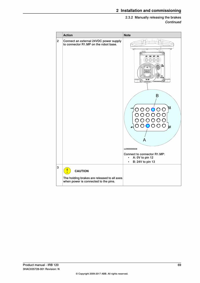
NoteAction
xx0900000638
Connect an external 24VDC power supplyto connector R1.MP on the robot base.
2
Connect to connector R1.MP:• A: 0V to pin 12• B: 24V to pin 13
CAUTION
The holding brakes are released to all axeswhen power is connected to the pins.
3
Product manual - IRB 120 693HAC035728-001 Revision: N
© Copyright 2009-2017 ABB. All rights reserved.
2 Installation and commissioning2.3.2 Manually releasing the brakes
Continued
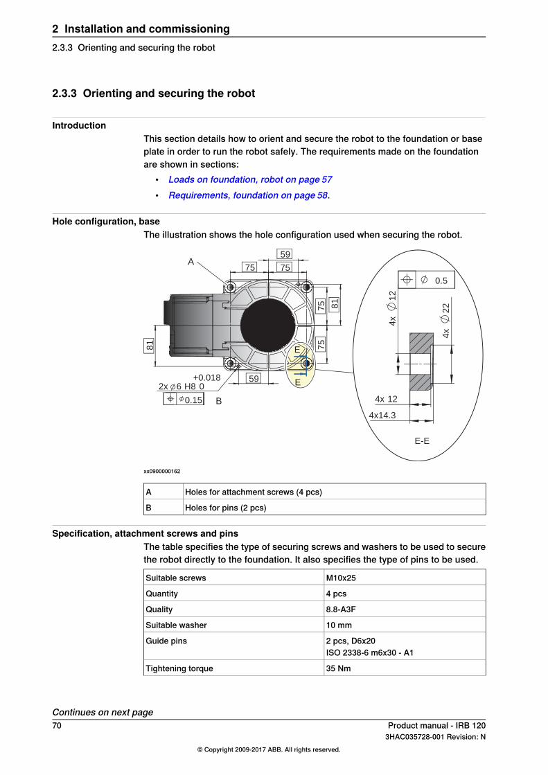
2.3.3 Orienting and securing the robot
IntroductionThis section details how to orient and secure the robot to the foundation or baseplate in order to run the robot safely. The requirements made on the foundationare shown in sections:
• Loads on foundation, robot on page 57• Requirements, foundation on page 58.
Hole configuration, baseThe illustration shows the hole configuration used when securing the robot.
0.5
E-E
4x
22
1212
4x
4x
4x14.3
0.15
2x
75
+0.0186
59 0H8
81
81
75
75
75
59 A
B
E
E
xx0900000162
Holes for attachment screws (4 pcs)A
Holes for pins (2 pcs)B
Specification, attachment screws and pinsThe table specifies the type of securing screws and washers to be used to securethe robot directly to the foundation. It also specifies the type of pins to be used.
M10x25Suitable screws
4 pcsQuantity
8.8-A3FQuality
10 mmSuitable washer
2 pcs, D6x20Guide pinsISO 2338-6 m6x30 - A1
35 NmTightening torque
Continues on next page70 Product manual - IRB 120
3HAC035728-001 Revision: N© Copyright 2009-2017 ABB. All rights reserved.
2 Installation and commissioning2.3.3 Orienting and securing the robot

xx0900000643
Level surface requirements
Orienting and securing the robotUse this procedure to orient and secure the robot.
InformationAction
Make sure the installation site for the robot con-forms to the specifications in section:
• Pre-installation procedure on page 56.
1
The hole configuration of the baseis shown in the figure in:
• Hole configuration, base onpage 70
Prepare the installation site with attachmentholes.
2
CAUTION
The robot weighs 25 kg. All lifting equipmentmust be sized accordingly!
3
CAUTION
When the robot is put down after being lifted ortransported, there is a risk of it tipping, if notproperly secured.
4
How to lift the robot is described insection:
• Lifting the robot with round-slings on page 63
Lift the robot to its installation site.5
2 pcs, D6x20Fit two pins to the holes in the base.6ISO 2338-6 m6x30 - A1
Make sure the robot base is cor-rectly fitted onto the pins.
Guide the robot gently, using the attachmentscrews while lowering it into its mounting posi-tion.
7
Screws: M10x25, quality: 8.8-A3FFit the securing screws andwashers in the attach-ment holes of the base.
8
Tightening torque:Tighten the bolts in a criss-cross pattern to en-sure that the base is not distorted.
935 Nm
Securing robot on a mounting plateWhen bolting a mounting plate or frame to a concrete floor, follow the generalinstructions for expansion-shell bolts.Screw joints must be able to withstand the stress loads defined in section Loadson foundation, robot on page 57.
Product manual - IRB 120 713HAC035728-001 Revision: N
© Copyright 2009-2017 ABB. All rights reserved.
2 Installation and commissioning2.3.3 Orienting and securing the robot
Continued

2.3.4 Fitting equipment on robot
IntroductionThe robot features mounting holes for additional equipment.Access to any of the following mounting holes may be obstructed by any additionalcabling, equipment, etc., fitted by the robot user. Make sure the required mountingholes are accessible when planning the robot cell.
Note
All equipment and cables used on the robot, must be designed and fitted not todamage the robot and/or its parts.
Note
Never drill a hole in the robot without first consulting ABB!
Maximum loadsThe table shows the maximum permitted loads for any extra equipment fitted inthe holes intended for this purpose. See figure in Fitting equipment on base andupper arm on page 73.
Max load B(upper arm)
Max load A(base, on each side)
Robot
0.3 kg0.5 kgIRB 120
Continues on next page72 Product manual - IRB 120
3HAC035728-001 Revision: N© Copyright 2009-2017 ABB. All rights reserved.
2 Installation and commissioning2.3.4 Fitting equipment on robot

Fitting equipment on base and upper armThe illustration shows the fitting holes available for fitting extra equipment on thebase and upper arm of the robot.
25±0.152xM4 8
25±0.15
2xM4 8A
B
53
187
D
C
xx0900000203
Load area base, max load 0.5 kg (on each side)A
Load area upper arm, max load 0.3 kgB
Max. 172 mmC
Max. radius 75 mmD
NOTE! Fitting holes at the base of the robot are placed on each side.
Continues on next pageProduct manual - IRB 120 733HAC035728-001 Revision: N
© Copyright 2009-2017 ABB. All rights reserved.
2 Installation and commissioning2.3.4 Fitting equipment on robot
Continued
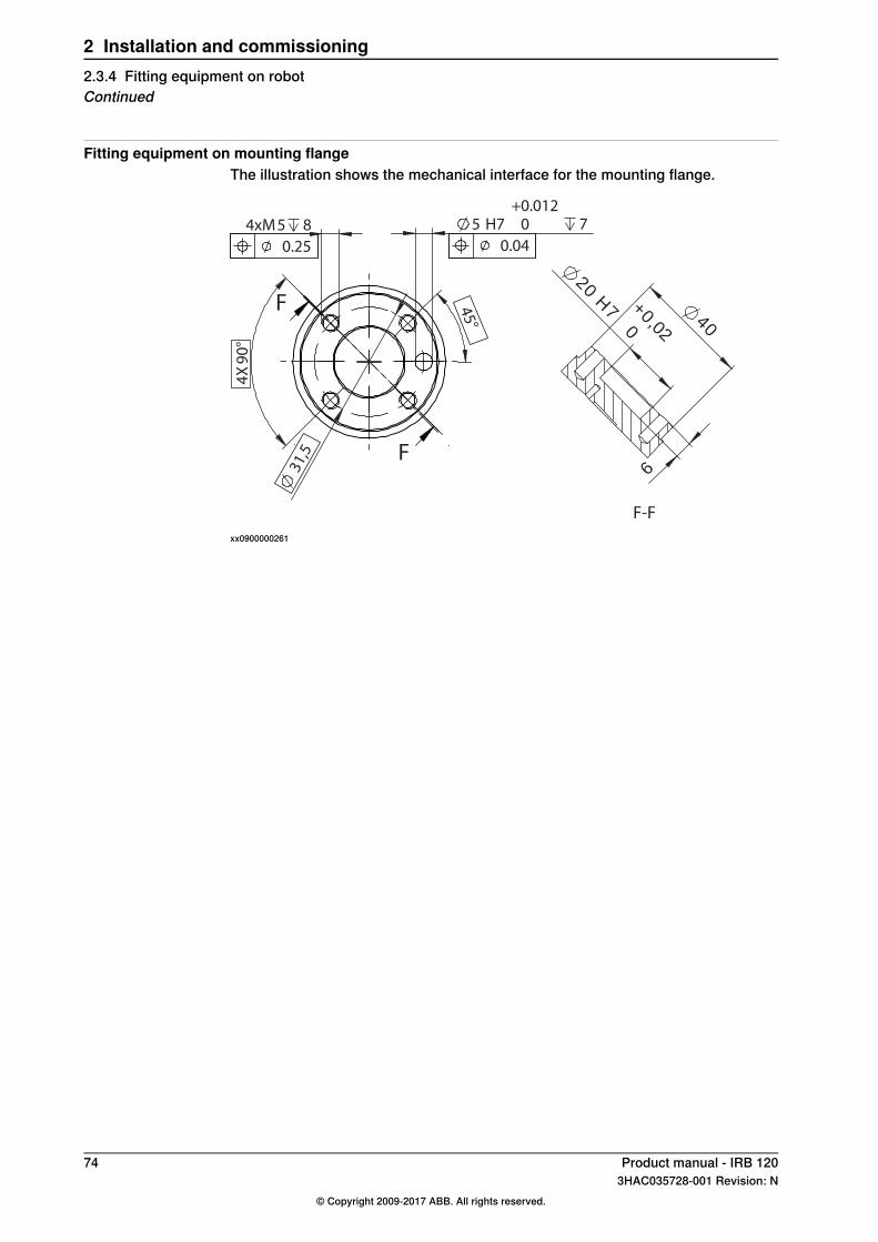
Fitting equipment on mounting flangeThe illustration shows the mechanical interface for the mounting flange.
F-F
0,02
+
20H7
0
6
40
4X
90
°4xM5 8 5 H7 0
+0.012
7
45
°
31
,5
F
F
0.25 0.04
xx0900000261
74 Product manual - IRB 1203HAC035728-001 Revision: N
© Copyright 2009-2017 ABB. All rights reserved.
2 Installation and commissioning2.3.4 Fitting equipment on robotContinued

2.3.5 Setting the system parameters for a suspended or tilted robot
GeneralThe robot is configured for mounting parallel to the floor, without tilting, on delivery.The method for mounting the robot in a suspended (upside down) or tilted positionis basically the same as for floor mounting, but the system parameters that describethe mounting angle (how the robot is oriented relative to the gravity) must beredefined.
Note
With suspended installation, make sure that the gantry or corresponding structureis rigid enough to prevent unacceptable vibrations and deflections, so thatoptimum performance can be achieved.
Note
The allowed mounting positions are described in the product specification forthe robot. The requirements on the foundation are described in Requirements,foundation on page 58.
The x-direction in the base coordinate systemIf the robot is wall mounted or mounted in a tilted position, it is important that thex-direction of the robot base coordinate system points downwards, as shown inthe following figure.
Y
Y+X
+X
Z
Z
xx1400000737
Continues on next pageProduct manual - IRB 120 753HAC035728-001 Revision: N
© Copyright 2009-2017 ABB. All rights reserved.
2 Installation and commissioning2.3.5 Setting the system parameters for a suspended or tilted robot
System parameters
Note
The mounting angle must be configured correctly in the system parameters sothat the robot system can control the movements in the best possible way. Anincorrect definition of the mounting angle will result in:
• Overloading the mechanical structure.• Lower path performance and path accuracy.• Some functions will not work properly, for example Load Identification and
Collision detection.
Gravity BetaIf the robot is mounted upside down or on a wall (rotated around the y-axis), thenthe robot base frame and the system parameter Gravity Beta must be redefined.Gravity Beta should then be π (±3.141593) if the robot is mounted upside down(suspended), or ±π/2 (±3.141593/2) if mounted on a wall.The Gravity Beta is a positive rotation direction around the y-axis in the basecoordinate system. The value is set in radians.
Gravity AlphaIf the robot is mounted on a wall (rotated around the x-axis), then the robot baseframe and the system parameter Gravity Alpha must be redefined. The value ofGravity Alpha should then be ±π/2 (±3.141593/2).The Gravity Alpha is a positive rotation direction around the x-axis in the basecoordinate system. The value is set in radians.
Note
The system parameter Gravity Alpha is not supported for all robot types. It is notsupported for IRB 140, IRB 1410, IRB 1600ID, IRB 2400, IRB 4400, IRB 6400R,IRB 6400 (except for IRB 6400 200/2.5 and IRB 6400 200/2.8), IRB 6600, IRB6650, IRB 6650S and IRB 7600 (except for IRB 7600 325/3.1).If the robot does not support Gravity Alpha, then use Gravity Beta along with therecalibration of axis 1 to define the rotation of the robot around the x-axis.
Note
The parameter is supported for all robots on track when the system parameter7 axes high performancemotion is set, see Technical referencemanual - Systemparameters.
Gamma RotationGamma Rotation defines the orientation of the robot foot on the travel carriage(track motion).
Continues on next page76 Product manual - IRB 120
3HAC035728-001 Revision: N© Copyright 2009-2017 ABB. All rights reserved.
2 Installation and commissioning2.3.5 Setting the system parameters for a suspended or tilted robotContinued
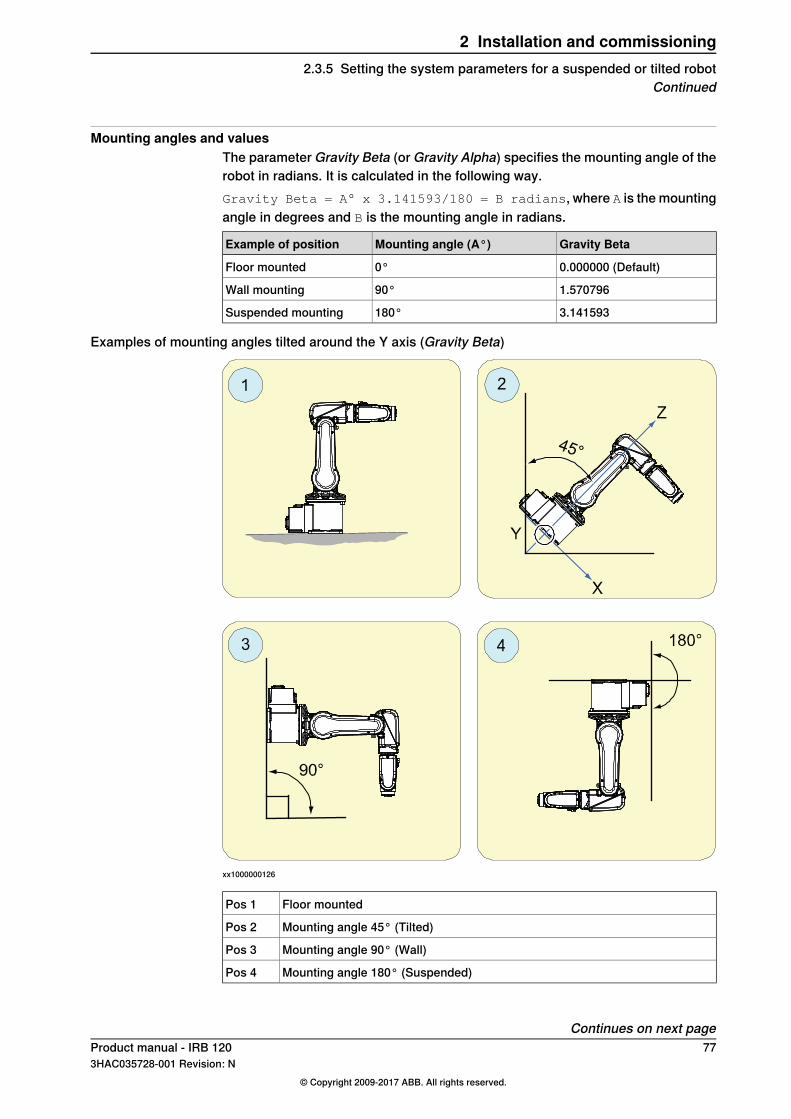
Mounting angles and valuesThe parameter Gravity Beta (or Gravity Alpha) specifies the mounting angle of therobot in radians. It is calculated in the following way.Gravity Beta = A° x 3.141593/180 = B radians, where A is the mountingangle in degrees and B is the mounting angle in radians.
Gravity BetaMounting angle (A°)Example of position
0.000000 (Default)0°Floor mounted
1.57079690°Wall mounting
3.141593180°Suspended mounting
Examples of mounting angles tilted around the Y axis (Gravity Beta)
xx1000000126
Floor mountedPos 1
Mounting angle 45° (Tilted)Pos 2
Mounting angle 90° (Wall)Pos 3
Mounting angle 180° (Suspended)Pos 4
Continues on next pageProduct manual - IRB 120 773HAC035728-001 Revision: N
© Copyright 2009-2017 ABB. All rights reserved.
2 Installation and commissioning2.3.5 Setting the system parameters for a suspended or tilted robot
Continued

Examples of mounting angles tilted around the X axis (Gravity Alpha)
-
xx1500000532
Gravity AlphaMounting anglePos
00° (Floor mounted)1
0.78539845° (Tilted)2
1.57079690° (Wall)3
-1.570796-90° (Wall)4
Note
For suspended robots (180°), it is recommended to use Gravity Beta instead ofGravity Alpha.
Defining the parameter in the IRC5 softwareThe value of the system parameters that define the mounting angle must beredefined when changing the mounting angle of the robot. The parameters belongto the type Robot, in the topic Motion.How to calculate a new value is detailed in Mounting angles and values on page77.
Continues on next page78 Product manual - IRB 120
3HAC035728-001 Revision: N© Copyright 2009-2017 ABB. All rights reserved.
2 Installation and commissioning2.3.5 Setting the system parameters for a suspended or tilted robotContinued

The system parameters are described in Technical reference manual - Systemparameters.The system parameters are redefined in the Configuration Editor, in RobotStudioor on the FlexPendant.
Product manual - IRB 120 793HAC035728-001 Revision: N
© Copyright 2009-2017 ABB. All rights reserved.
2 Installation and commissioning2.3.5 Setting the system parameters for a suspended or tilted robot
Continued

2.3.6 Loads fitted to the robot, stopping time and braking distances
GeneralAny loads mounted on the robot must be defined correctly and carefully (withregard to the position of center of gravity and mass moments of inertia) in orderto avoid jolting movements and overloading motors, gears and structure.
CAUTION
Incorrectly defined loads may result in operational stops or major damage to therobot.
ReferencesLoad diagrams, permitted extra loads (equipment) and their positions are specifiedin the product specification. The loads must also be defined in the software asdetailed in:
• Operating manual - IRC5 with FlexPendant
Stopping time and braking distancesThe performance of the motor brake depends on if there are any loads attachedto the robot. For more information, see product specification for the robot.
80 Product manual - IRB 1203HAC035728-001 Revision: N
© Copyright 2009-2017 ABB. All rights reserved.
2 Installation and commissioning2.3.6 Loads fitted to the robot, stopping time and braking distances

2.4 Restricting the working range
2.4.1 Axes with restricted working range
GeneralWhen installing the robot, make sure that it can move freely within its entire workingspace. If there is a risk that it may collide with other objects, its working spaceshould be limited.The working range of the following axes may be restricted:This section describes how to install hardware that restricts the working range.
Note
Adjustments must also be made in the robot configuration software (systemparameters). References to relevant manuals are included in the installationprocedures.
Product manual - IRB 120 813HAC035728-001 Revision: N
© Copyright 2009-2017 ABB. All rights reserved.
2 Installation and commissioning2.4.1 Axes with restricted working range

2.4.2 Mechanically restricting the working range
Location of mechanical stopsThe figures shows where the mechanical stops are placed on the robot.
xx1000000002
Mechanical stop axis 1 (base)A
Mechanical stop axis 1 (swing plate)B
xx0900000583
Mechanical stop axis 2 (swing housing)A
Mechanical stops axis 2 (upper arm)B
Continues on next page82 Product manual - IRB 120
3HAC035728-001 Revision: N© Copyright 2009-2017 ABB. All rights reserved.
2 Installation and commissioning2.4.2 Mechanically restricting the working range

xx1000000003
Mechanical stop axis 3 (lower arm)A
Mechanical stops axis 2 (lower arm)B
Product manual - IRB 120 833HAC035728-001 Revision: N
© Copyright 2009-2017 ABB. All rights reserved.
2 Installation and commissioning2.4.2 Mechanically restricting the working range
Continued
2.5 Making robot ready for operation
2.5.1 Additional installation procedure, Clean Room
GeneralRobots with protection type Clean Room are specially designed to work in a cleanroom environment.Clean Room robots are designed to prevent from particle emission from the robot.For example, the maintenance work possible to perform without cracking the paint.The robot is painted with four layers of polyurethane paint. The last layer being avarnish over labels to simplify cleaning. The paint has been tested regardingoutgassing of Volatile Organic Compounds (VOC) and been classified in accordancewith ISO 14644-8.Any Clean Room parts that are replaced must be replaced with parts designed foruse in Clean Room environments.
Clean Room class 5According to IPA test result, the robot IRB 120 is suitable for use in Clean Roomenvironment when these requirements are fulfilled:
• Air cleanliness Class 5 according to ISO 14644-1, when operated at a velocityof 50%.
• Air cleanliness Class 4 according to ISO 14644-1, when operated at a velocityof 100%.
Classification of airborne molecular contamination
Outgassing amountParameter
Classifica-tion in ac-cordance toISO 14644-8
Norm basedon 1m2and1s(g)
Total detec-ted (ng)
Performedtest
Temp (°C)Test dura-tion (s)
Area (m2 )
-6.81.7E-072848TVOC2336004.5E-03
-3.81.7E-0446524TVOC90604.5E-03
Preparations before commissioning a Clean Room robotDuring transport and handling of a Clean Room robot, it is likely that the robot hasbeen contaminated with particles of different kinds. Therefore the robot must becarefully cleaned before installation.Do not apply force on the plastic covers when lifting the robot! This may result indamage or cracks in the paint around the plastic cover.
84 Product manual - IRB 1203HAC035728-001 Revision: N
© Copyright 2009-2017 ABB. All rights reserved.
2 Installation and commissioning2.5.1 Additional installation procedure, Clean Room
2.6 Electrical connections
2.6.1 Robot cabling and connection points
IntroductionConnect the robot and the controller to each other after securing them to thefoundation. The lists specify which cables to use for each respective application.
Connection point locationsFor information about the connection point locations, see the chapter Circuitdiagram.
Main cable categoriesAll cables between the robot and controller are divided into the following categories:
DescriptionCable category
Handles power supply to, and the control of the robot’s motorsas well as feedback from the encoder interface board.
Robot cables
Specified in the table in Robot cable, power on page 85.
The cable categories are divided into sub-categories. See Robot cables on page85.
Robot cablesThe robot cable is included in the standard delivery of the robot. They are completelypre-manufactured and ready to plug in.
Connectionpoint, robot
Connectionpoint, cabinet
DescriptionCable sub-category
R1.MPXS1Transfers drive powerfrom the drive units inthe control cabinet to therobot motors
Robot cable, power
R1.SMBXS2Transfers encoder datafrom and power supplyto the encoder interfaceboard.
Robot cable, signal
Robot cable, power
Art. no.Cable
3HAC032694-001Robot cable, power: L=3 m
3HAC032695-001Robot cable, power: L=7 m
3HAC032696-001Robot cable, power: L=15 m
Robot cable, signal
Art. no.Cable
3HAC035320-001Robot cable, signal: L=3 m
3HAC2493-1Robot cable, signal: L=7 m
3HAC2530-1Robot cable, signal: L=15 m
Continues on next pageProduct manual - IRB 120 853HAC035728-001 Revision: N
© Copyright 2009-2017 ABB. All rights reserved.
2 Installation and commissioning2.6.1 Robot cabling and connection points

Bending radius for static floor cablesThe minimum bending radius is 10 times the cable diameter for static floor cables.
A
B
xx1600002016
DiameterA
Diameter x10B
86 Product manual - IRB 1203HAC035728-001 Revision: N
© Copyright 2009-2017 ABB. All rights reserved.
2 Installation and commissioning2.6.1 Robot cabling and connection pointsContinued

2.6.2 Customer connections on the robot
IntroductionThe customer cables are integrated in the robot and the connectors are placed onthe upper arm housing and at the base.
ConnectorsThe tables describes the connectors on base and upper arm housing.
Connectors, base
Art. no.DescriptionPosition
3HAC022117-002UTOW71210PH06 pin connector 10p,bulkhead
Robot
3HAC037038-001Connector set R1.CP/CSCustomer connector
Connectors, upper arm housing
Art. no.DescriptionPosition
3HAC023624-002UTOW01210SH05 socket connector 10p,flange mounted
Robot
3HAC037070-001Connector set R3.CP/CSCustomer connector
Air, connector
Art. no.DescriptionPosition
4xM5Robot
3HAC032049-001SMC KJS04-M5 air connectorCustomer cable
Continues on next pageProduct manual - IRB 120 873HAC035728-001 Revision: N
© Copyright 2009-2017 ABB. All rights reserved.
2 Installation and commissioning2.6.2 Customer connections on the robot

Customer connectionsThe location of the customer connections on the base and at the upper arm housing,are shown in the figures:
Customer connections, baseCustomer connections, base.
A
B
xx0900000639
ValueNumberDescriptionConnectionPos
49 V, 500 mA10Customer power/signalR1.CP/CSA
Inner house diameter 4 mm4Max 5 barAirB
Customer connections, upper arm housingCustomer connections, upper arm housing.
BA
xx0900000640
ValueNumberDescriptionConnectionPos
49 V, 500 mA10Customer power/signalR3.CP/CSA
Inner house diameter 4 mm4Max 5 barAirB
88 Product manual - IRB 1203HAC035728-001 Revision: N
© Copyright 2009-2017 ABB. All rights reserved.
2 Installation and commissioning2.6.2 Customer connections on the robotContinued

2.7 Start of robot in cold environments
IntroductionThis section describes how to start the robot in a cold environment if it is not startingthe normal way.
Problems with starting the robot
Event message from Motion supervisionUse this procedure if an event message indicates a problem with Motion supervisionat start-up.
NoteAction
Turn off motion supervision.1
Start the robot.2
When the robot has reached normal working temper-ature, the motion supervision can be turned onagain.
3
Robot stopping with other event messageUse this procedure if the robot is not starting.
NoteAction
The speed can be regulated with theRAPID instruction VelSet.
Start the robot with its normal program butwith reduced speed.
1
Adjusting the speed and acceleration during warm-upDepending on how cold the environment is and what program is being used, thespeed might need to be ramped up until reached maximum. The table showsexamples of how to adjust the speed:
Speed/velocityAccSetWork cycles
v100 (100 mm/s)20, 203 Work cycles
v400 (400 mm/s)40, 405 Work cycles
v600 (600 mm/s)60, 605 Work cycles
v1000 (1000 mm/s)100, 1005 Work cycles
Max.100, 100More than 5 Work cycles
If the program consists of large wrist movements, it is possible that the reorientationvelocity, which is always high in predefined velocities, needs to be included in theramping up.
Product manual - IRB 120 893HAC035728-001 Revision: N
© Copyright 2009-2017 ABB. All rights reserved.
2 Installation and commissioning2.7 Start of robot in cold environments

This page is intentionally left blank

3 Maintenance3.1 Introduction
Structure of this chapterThis chapter describes all the maintenance activities recommended for the IRB120.It is based on the maintenance schedule found at the beginning of the chapter.The schedule contains information about required maintenance activities includingintervals, and refers to procedures for the activities.Each procedure contains all the information required to perform the activity,including required tools and materials.The procedures are gathered in different sections and divided according to themaintenance activity.
Safety informationObserve all safety information before conducting any service work!There are general safety aspects that must be read through, as well as more specificsafety information that describes the danger and safety risks when performing theprocedures. Read the chapter Safety on page 17 before performing any servicework!
Note
If the IRB 120 is connected to power, always make sure that the IRB 120 isconnected to protective earth before starting any maintenance work!For more information see:
• Product manual - IRC5
Product manual - IRB 120 913HAC035728-001 Revision: N
© Copyright 2009-2017 ABB. All rights reserved.
3 Maintenance3.1 Introduction

3.2 Maintenance schedule
3.2.1 Specification of maintenance intervals
IntroductionThe intervals are specified in different ways depending on the type of maintenanceactivity to be carried out and the working conditions of the IRB 120:
• Calendar time: specified in months regardless of whether the system isrunning or not.
• Operating time: specified in operating hours. More frequent running meansmore frequent maintenance activities.
• SIS: specified by the robot's SIS (Service Information System). A typicalvalue is given for a typical work cycle, but the value will differ depending onhow hard each part is run. The SIS used in M2004 is further described in theOperating manual - Service Information System.
92 Product manual - IRB 1203HAC035728-001 Revision: N
© Copyright 2009-2017 ABB. All rights reserved.
3 Maintenance3.2.1 Specification of maintenance intervals

3.2.2 Maintenance schedule
GeneralThe robot, consisting of robot and controller cabinet, must be maintained regularlyto ensure its function. The maintenance activities and their respective intervals arespecified in the table below.Non-predictable situations also give rise to inspections of the robot. Any damagesmust be attended to immediately!The inspection intervals do not specify the life of each component.
Activities and intervals, standard equipmentThe sections referred to in the table can be found in the different chapters for everymaintenance activity.The table below specifies the required maintenance activities and intervals:
Detailed in section:IntervalEquipmentMaintenanceactivity
Check for abnormal wearor contamination
Regularly i
For Clean Room robots:Daily
RobotInspection
Inspecting dampers onpage 99
Regularly iDamper, axes 1, 2and 3
Inspection
Inspecting the robotcabling on page 95
Regularly iCable harnessesInspection
Inspecting timing belts onpage 101
36 mthsii
Timing beltsInspection
Inspecting plastic coverson page 105
Regularly iPlastic coversInspection
Inspecting mechanicalstops on page 96
Regularly iMechanical stoppins
Inspection
Replacing the batterypack on page 109
36 months or battery lowalert iii
Battery pack,measurementsystem of typeRMU101 orRMU102 (3-polebattery contact)
Replacement
Replacing the batterypack on page 109
Battery low alert ivBattery pack,measurementsystem with 2-pole battery con-tact, e.g.DSQC633A
Replacement
Cleaning the IRB 120 onpage 112
Regularly iComplete robotCleaning
i "Regularly" implies that the activity is to be performed regularly, but the actual interval may not bespecified by the robot manufacturer. The interval depends on the operation cycle of the robot, itsworking environment and movement pattern. Generally, the more contaminated environment, theshorter intervals. The more demanding movement pattern (sharper bending cable harness), theshorter intervals.
ii Service inspection including dismounting of robot parts shall always be done outside the cleanroom area.
Continues on next pageProduct manual - IRB 120 933HAC035728-001 Revision: N
© Copyright 2009-2017 ABB. All rights reserved.
3 Maintenance3.2.2 Maintenance schedule

iii The battery low alert (38213Battery charge low) is displayed when the battery needs to be replaced.The recommendation to avoid an unsynchronized robot is to keep the power to the controller turnedon until the battery is to be replaced.See the replacement instruction for more details.
iv The battery low alert (38213 Battery charge low) is displayed when remaining backup capacity(robot powered off) is less than 2 months. The typical lifetime of a new battery is 36 months if therobot is powered off 2 days/week or 18 months if the robot is powered off 16 h/day. The lifetimecan be extended with a battery shutdown service routine. See Operating manual - IRC5 withFlexPendant for instructions.
94 Product manual - IRB 1203HAC035728-001 Revision: N
© Copyright 2009-2017 ABB. All rights reserved.
3 Maintenance3.2.2 Maintenance scheduleContinued

3.3 Inspection activities
3.3.1 Inspecting the robot cabling
Introduction
CAUTION
Always read the specific instructions if the robot has protection type Clean Room,before doing any repair work, see Replacing parts on the robot on page 118
Location of robot cablingThe robot cabling comprises the cabling between the robot and controller cabinet.
Required tools and equipmentVisual inspection, no tools are required.Other tools and procedures may be required if the spare part needs to be replaced.These are specified in the replacement procedure.
Inspection, robot cablingUse this procedure to inspect the robot cabling.
NoteAction
DANGER
Turn off all:• electric power supply to the robot• hydraulic pressure supply to the robot• air pressure supply to the robot
Before entering the robot working area.
1
Visually inspect:• the control cabling between the robot and
control cabinetLook for abrasions, cuts or crush damages.
2
Replace the cabling if wear or damage is detected.3
Product manual - IRB 120 953HAC035728-001 Revision: N
© Copyright 2009-2017 ABB. All rights reserved.
3 Maintenance3.3.1 Inspecting the robot cabling
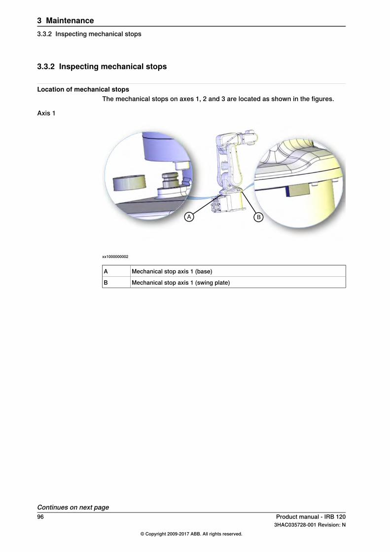
3.3.2 Inspecting mechanical stops
Location of mechanical stopsThe mechanical stops on axes 1, 2 and 3 are located as shown in the figures.
Axis 1
xx1000000002
Mechanical stop axis 1 (base)A
Mechanical stop axis 1 (swing plate)B
Continues on next page96 Product manual - IRB 120
3HAC035728-001 Revision: N© Copyright 2009-2017 ABB. All rights reserved.
3 Maintenance3.3.2 Inspecting mechanical stops
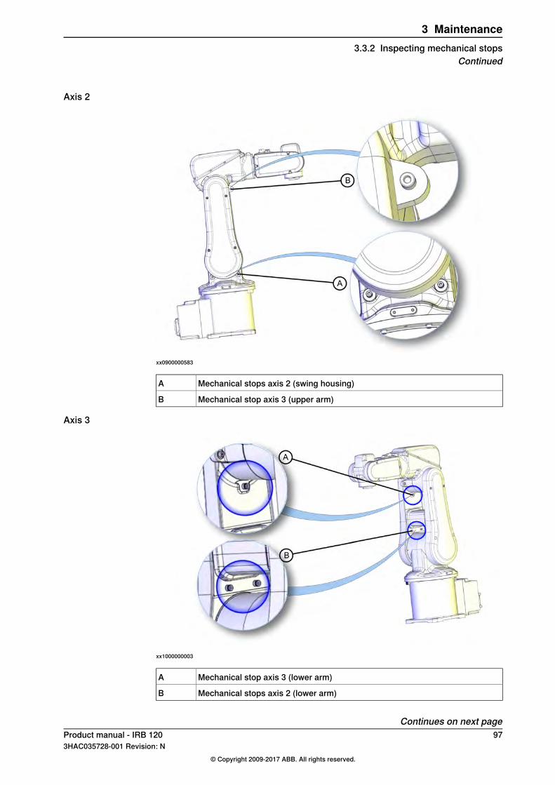
Axis 2
xx0900000583
Mechanical stops axis 2 (swing housing)A
Mechanical stop axis 3 (upper arm)B
Axis 3
xx1000000003
Mechanical stop axis 3 (lower arm)A
Mechanical stops axis 2 (lower arm)B
Continues on next pageProduct manual - IRB 120 973HAC035728-001 Revision: N
© Copyright 2009-2017 ABB. All rights reserved.
3 Maintenance3.3.2 Inspecting mechanical stops
Continued
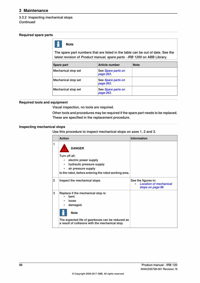
Required spare parts
Note
The spare part numbers that are listed in the table can be out of date. See thelatest revision of Product manual, spare parts - IRB 1200 on ABB Library.
NoteArticle numberSpare part
See Spare parts onpage 263.
Mechanical stop set
See Spare parts onpage 263.
Mechanical stop set
See Spare parts onpage 263.
Mechanical stop set
Required tools and equipmentVisual inspection, no tools are required.Other tools and procedures may be required if the spare part needs to be replaced.These are specified in the replacement procedure.
Inspecting mechanical stopsUse this procedure to inspect mechanical stops on axes 1, 2 and 3.
InformationAction
DANGER
Turn off all:• electric power supply• hydraulic pressure supply• air pressure supply
to the robot, before entering the robot working area.
1
See the figures in:• Location of mechanical
stops on page 96
Inspect the mechanical stops.2
Replace if the mechanical stop is:• bent• loose• damaged.
Note
The expected life of gearboxes can be reduced asa result of collisions with the mechanical stop.
3
98 Product manual - IRB 1203HAC035728-001 Revision: N
© Copyright 2009-2017 ABB. All rights reserved.
3 Maintenance3.3.2 Inspecting mechanical stopsContinued

3.3.3 Inspecting dampers
Location of dampersThe location of dampers are shown in the figures.
xx0900000579
Damper, axis 1A
Mechanical stop axis 1 (swing plate)B
xx0900000582
Damper, axis 3A
Dampers, axis 2B
Required equipment
NoteArt. no.Equipment
The content is defined in the section Standard toolkit onpage 260.
-Standard toolkit
Continues on next pageProduct manual - IRB 120 993HAC035728-001 Revision: N
© Copyright 2009-2017 ABB. All rights reserved.
3 Maintenance3.3.3 Inspecting dampers

Inspecting dampersUse this procedure to inspect the dampers.
InformationAction
DANGER
Turn off all electric power, hydraulic and pneu-matic pressure supplies to the robot!
1
See the figure in:• Location of dampers on
page 99
Check all dampers for damage such as:• cracks• existing impressions larger than 1 mm.
2
Check all attachment screws for deformation.3
If any damage is detected, the damper must bereplaced with a new one!
4
100 Product manual - IRB 1203HAC035728-001 Revision: N
© Copyright 2009-2017 ABB. All rights reserved.
3 Maintenance3.3.3 Inspecting dampersContinued
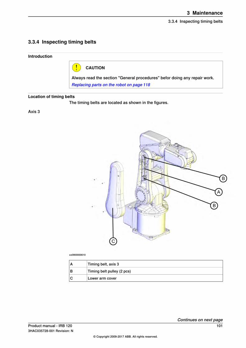
3.3.4 Inspecting timing belts
Introduction
CAUTION
Always read the section "General procedures" befor doing any repair work.Replacing parts on the robot on page 118
Location of timing beltsThe timing belts are located as shown in the figures.
Axis 3
xx0900000610
Timing belt, axis 3A
Timing belt pulley (2 pcs)B
Lower arm coverC
Continues on next pageProduct manual - IRB 120 1013HAC035728-001 Revision: N
© Copyright 2009-2017 ABB. All rights reserved.
3 Maintenance3.3.4 Inspecting timing belts

Axis 5
xx0900000611
Wrist side coverA
Timing belt pulley (2 pcs)B
Timing belt, axis 5C
Required tools and equipment
NoteEquipment
The content is defined in the section Stand-ard toolkit on page 260.
Standard toolkit
Other tools and procedures may be requiredif the spare part needs to be replaced. Theseare specified in the replacement procedure.
Timing belt tensionThe table describes the timing belt tension.
Timing belt tensionAxis
New belt: F = 18-19.7NAxis 3Used belt: F = 12.5-14.3N
New belt: F = 7.6-8.4NAxis 5Used belt: F = 5.3-6.1N
Continues on next page102 Product manual - IRB 120
3HAC035728-001 Revision: N© Copyright 2009-2017 ABB. All rights reserved.
3 Maintenance3.3.4 Inspecting timing beltsContinued
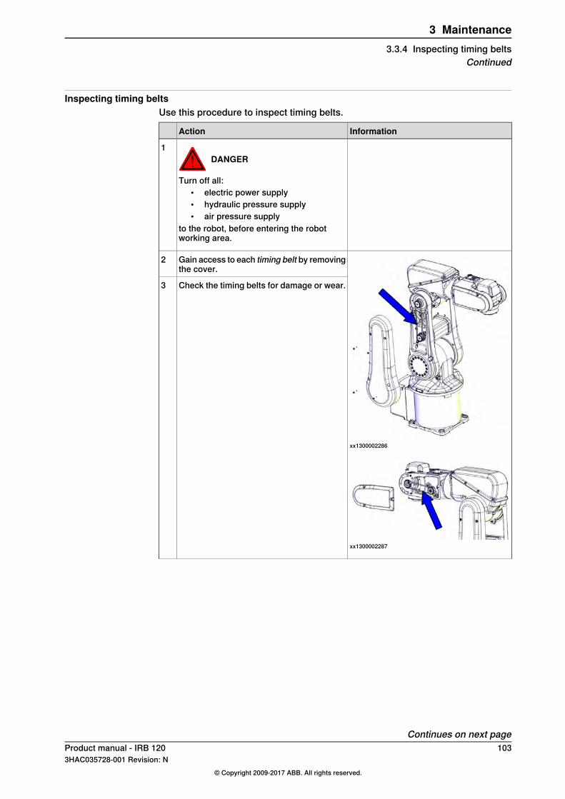
Inspecting timing beltsUse this procedure to inspect timing belts.
InformationAction
DANGER
Turn off all:• electric power supply• hydraulic pressure supply• air pressure supply
to the robot, before entering the robotworking area.
1
xx1300002286
xx1300002287
Gain access to each timing belt by removingthe cover.
2
Check the timing belts for damage or wear.3
Continues on next pageProduct manual - IRB 120 1033HAC035728-001 Revision: N
© Copyright 2009-2017 ABB. All rights reserved.
3 Maintenance3.3.4 Inspecting timing belts
Continued

InformationAction
xx1300002288
xx1300002289
Check the timing belt pulleys for damage.4
If any damage or wear is detected, the partmust be replaced!
5
Axis 3: .Check each belt for tension.6New belt: F = 18-19.7NIf the belt tension is not correct, adjust it!Used belt: F = 12.5-14.3NAxis 5: .New belt: F = 7.6-8.4NUsed belt: F = 5.3-6.1N
104 Product manual - IRB 1203HAC035728-001 Revision: N
© Copyright 2009-2017 ABB. All rights reserved.
3 Maintenance3.3.4 Inspecting timing beltsContinued
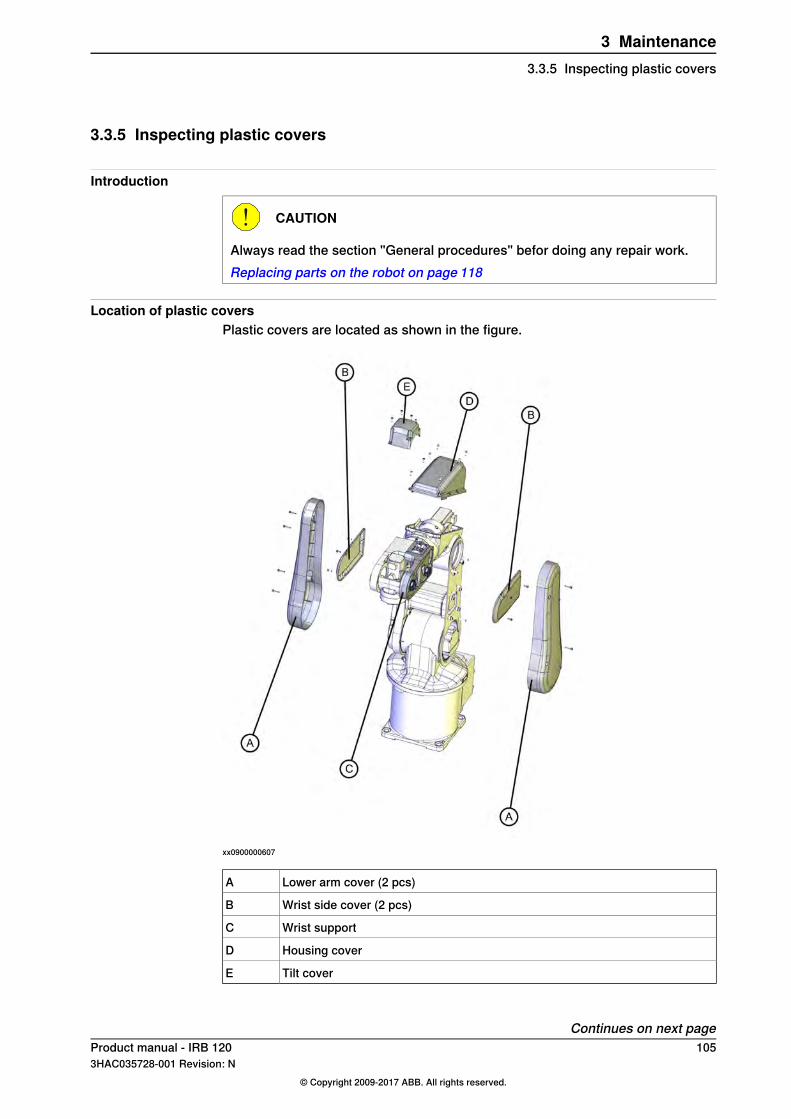
3.3.5 Inspecting plastic covers
Introduction
CAUTION
Always read the section "General procedures" befor doing any repair work.Replacing parts on the robot on page 118
Location of plastic coversPlastic covers are located as shown in the figure.
xx0900000607
Lower arm cover (2 pcs)A
Wrist side cover (2 pcs)B
Wrist supportC
Housing coverD
Tilt coverE
Continues on next pageProduct manual - IRB 120 1053HAC035728-001 Revision: N
© Copyright 2009-2017 ABB. All rights reserved.
3 Maintenance3.3.5 Inspecting plastic covers
Inspecting plastic coversUse this procedure to inspect the plastic covers on the robot.
InformationAction
DANGER
Turn off all electric power, hydraulic and pneumaticpressure supplies to the robot!
1
Check the plastic covers for:• cracks• other kind of damage.
2
Replace the plastic cover if cracks or damage isdetected.
3
106 Product manual - IRB 1203HAC035728-001 Revision: N
© Copyright 2009-2017 ABB. All rights reserved.
3 Maintenance3.3.5 Inspecting plastic coversContinued

3.4 Replacement/changing activities
3.4.1 Type of lubrication in gearboxes
IntroductionThis section describes where to find information about the type of lubrication,article number and the amount of lubrication in the specific gearbox. It alsodescribes the equipment needed when working with lubrication.
CAUTION
Always read the specific instructions for Clean Room robots before doing anyrepair work, see Replacing parts on the robot on page 118.
Type and amount of oil in gearboxesInformation about the type of lubrication, article number as well as the amount inthe specific gearbox can be found in Technical reference manual - Lubrication ingearboxes on the Documentation DVD (released twice a year). The revision of themanual published on the Documentation DVD, will contain the latest updates whenthe Documentation DVD is released.Before starting any inspection, maintenance, or changing activities of lubrication,always contact the local ABB Service organization for more information.For ABB personnel: Always check ABB Library for the latest revision of the manualTechnical reference manual - Lubrication in gearboxes, in order to always get thelatest information of updates about lubrication in gearboxes. A new revision willbe published on ABB Library immediately after any updates. Therefore the manualpublished on the documentation DVD may not contain the latest updates aboutlubrication.
Continues on next pageProduct manual - IRB 120 1073HAC035728-001 Revision: N
© Copyright 2009-2017 ABB. All rights reserved.
3 Maintenance3.4.1 Type of lubrication in gearboxes

Location of gearboxesThe figure shows the location of the gearboxes.
xx0900000612
Gearbox. axis 1 (inside the base)A
Gearbox, axis 2B
Gearbox, axis 3C
Gearbox, axis 4D
Gearbox, axis 5E
Gearbox, axis 6F
Equipment
NoteEquipment
Includes pump with outlet pipe.Oil dispenserUse the suggested dispenser or a similar one:
• Orion OriCan article number 22590(pneumatic)
Nipple for quick connect fitting, with o-ring
108 Product manual - IRB 1203HAC035728-001 Revision: N
© Copyright 2009-2017 ABB. All rights reserved.
3 Maintenance3.4.1 Type of lubrication in gearboxesContinued
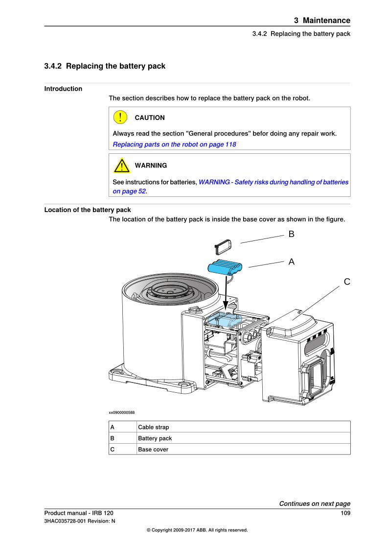
3.4.2 Replacing the battery pack
IntroductionThe section describes how to replace the battery pack on the robot.
CAUTION
Always read the section "General procedures" befor doing any repair work.Replacing parts on the robot on page 118
WARNING
See instructions for batteries,WARNING - Safety risks during handling of batterieson page 52.
Location of the battery packThe location of the battery pack is inside the base cover as shown in the figure.
A
B
C
xx0900000588
Cable strapA
Battery packB
Base coverC
Continues on next pageProduct manual - IRB 120 1093HAC035728-001 Revision: N
© Copyright 2009-2017 ABB. All rights reserved.
3 Maintenance3.4.2 Replacing the battery pack
Required equipment
NoteEquipment
The content is defined in the section Standardtoolkit on page 260.
Standard toolkit
These procedures include references to the toolsrequired.
Other tools and procedures may be re-quired. See references to these proced-ures in the step-by-step instructions be-low.
Removing the battery packUse this procedure to remove the battery pack.
InformationAction
DANGER
Turn off all electric power, hydraulic and pneu-matic pressure supplies to the robot!
1
CAUTION
Always cut the paint with a knife and grind thepaint edge when disassembling parts of a CleanRoom robot! See Replacing parts on the roboton page 118
2
The battery pack is located inside thebase cover as shown in the figure in:
• Location of the battery pack onpage 109
Remove the base cover from the robot by re-moving its attachment screws.
3
Disconnect the battery cable from the EncoderInterface Board.
4
Cut the cable strap.5
Remove the battery pack.6
Refitting the battery packUse this procedure to refit the battery pack.
InformationAction
Clean Room robots: clean the joints that have beenopened. See Replacing parts on the robot onpage 118
1
See the figure in:• Location of the battery
pack on page 109
Fit the new battery pack with a cable strap.2
Connect the battery cable to the Encoder InterfaceBoard.
3
See the figure in:• Location of the battery
pack on page 109
Refit the base cover to the robot with its attachmentscrews.
4
Continues on next page110 Product manual - IRB 120
3HAC035728-001 Revision: N© Copyright 2009-2017 ABB. All rights reserved.
3 Maintenance3.4.2 Replacing the battery packContinued
InformationAction
Clean Room robots: seal and paint the joints thathave been opened. See Replacing parts on the ro-bot on page 118
Note
After all repair work, wipe the robot free fromparticles with spirit on a lint free cloth.
5
Update the revolution counters.6
Product manual - IRB 120 1113HAC035728-001 Revision: N
© Copyright 2009-2017 ABB. All rights reserved.
3 Maintenance3.4.2 Replacing the battery pack
Continued

3.5 Cleaning activities
3.5.1 Cleaning the IRB 120
WARNING
Turn off all electrical power supplies to the manipulator before entering its workspace.
GeneralTo secure high uptime it is important that the IRB 120 is cleaned regularly. Thefrequency of cleaning depends on the environment in which the manipulator works.Different cleaning methods are allowed depending on the type of protection of theIRB 120.
Note
Always verify the protection type of the robot before cleaning.
Dos and don'ts!This section specifies some special considerations when cleaning the robot.Always!
• Always use cleaning equipment as specified! Any other cleaning equipmentmay shorten the life of the robot.
• Always check that all protective covers are fitted to the robot before cleaning!Never!
• Never use compressed air to clean the robot!• Never use solvents that are not approved by ABB to clean the robot!• Never remove any covers or other protective devices before cleaning the
robot!
Cleaning methodsThese following table defines what cleaning methods are allowed for ABBmanipulators depending on the protection type.
Cleaning methodProtectiontype
High pressure water orsteam
Rinse with waterWipewith clothVacuumcleaner
NoNoYes. With lightcleaning deter-gent.
YesStandard
NoNoYes. With lightcleaning deter-gent, spirit orisopropyl alco-hol.
YesClean room
Continues on next page112 Product manual - IRB 120
3HAC035728-001 Revision: N© Copyright 2009-2017 ABB. All rights reserved.
3 Maintenance3.5.1 Cleaning the IRB 120

Wiping with cloth
Additional cleaning instructions for robots with food grade lubricationMake sure that no liquid flows into the robot or stagnates in any gap or surfaceafter cleaning.
CablesMovable cables need to be able to move freely:
• Remove waste material, such as sand, dust and chips, if it prevents cablemovement.
• Clean the cables if they have a crusty surface, for example from dry releaseagents.
Product manual - IRB 120 1133HAC035728-001 Revision: N
© Copyright 2009-2017 ABB. All rights reserved.
3 Maintenance3.5.1 Cleaning the IRB 120
Continued

This page is intentionally left blank
4 Repair4.1 Introduction
Structure of this chapterThis chapter describes all repair activities recommended for the IRB 120 and anyexternal unit.It is made up of separate procedures, each describing a specific repair activity.Each procedure contains all the information required to perform the activity, forexample spare parts numbers, required special tools, and materials.
WARNING
Repair activities not described in this chapter must only be carried out by ABB.Otherwise damage to the mechanics and electronics may occur.
Required equipmentThe details of the equipment required to perform a specific repair activity are listedin the respective procedures.The details of equipment are also available in different lists in the chapter Referenceinformation on page 255.
Safety informationThere are general safety information and specific safety information. The specificsafety information describes the danger and safety risks while performing specificsteps in a procedure. Make sure to read through the chapter Safety on page 17before commencing any service work.
Note
If the IRB 120 is connected to power, always make sure that the IRB 120 isconnected to earth before starting any repair work.For more information see:
• Product manual - IRC5
Product manual - IRB 120 1153HAC035728-001 Revision: N
© Copyright 2009-2017 ABB. All rights reserved.
4 Repair4.1 Introduction

4.2 General procedures
4.2.1 Mounting instructions for seals
GeneralThis section describes how to mount different types of seals onto the robot.
Equipment
NoteArticle numberEquipment, etc.
Used to lubricate the seals.3HAB3537-1Grease
Used to lubricate the seals ofrobots with food grade lubric-ation.
3HAC043771-001Grease
Rotating sealsThe procedure below describes how to fit rotating seals.
CAUTION
Please observe the following before commencing any assembly of seals:• Protect the sealing surfaces during transport and mounting.• Keep the seal in its original wrappings or protect it well before actual
mounting.• The fitting of seals and gears must be carried out on clean workbenches.• Use a protective sleeve for the sealing lip during mounting, when sliding
over threads, keyways, etc.
NoteAction
Check the seal to ensure that:• The seal is of the correct type (provided with cutting
edge).• There is no damage to the sealing edge (feel with a
fingernail).
1
Inspect the sealing surface before mounting. If scratchesor damage are found, the seal must be replaced since itmay result in future leakage.
2
Article number is specifiedin Equipment on page116.
Lubricate the seal with grease just before fitting. (Not tooearly - there is a risk of dirt and foreign particles adheringto the seal.)
3
Fill 2/3 of the space between the dust tongue and sealinglip with grease. The rubber coated external diameter mustalso be greased, unless otherwise specified.
Mount the seal correctly with a mounting tool.4Never hammer directly on the seal as this may result inleakage.
Make sure no grease left on the robot surface.5
Continues on next page116 Product manual - IRB 120
3HAC035728-001 Revision: N© Copyright 2009-2017 ABB. All rights reserved.
4 Repair4.2.1 Mounting instructions for seals
Flange seals and static sealsThe following procedure describes how to fit flange seals and static seals.
Action
Check the flange surfaces. They must be even and free from pores.1It is easy to check flatness using a gauge on the fastened joint (without sealing com-pound).If the flange surfaces are defective, the parts may not be used because leakage couldoccur.
Clean the surfaces properly in accordance with the recommendations of ABB.2
Distribute the sealing compound evenly over the surface, preferably with a brush.3
Tighten the screws evenly when fastening the flange joint.4
O-ringsThe following procedure describes how to fit o-rings.
NoteAction
Ensure that the correct o-ring size is used.1
Defective o-rings, including damagedor deformed o-rings, may not be used.
Check the o-ring for surface defects, burrs,shape accuracy, or deformation.
2
Defective o-rings may not be used.Check the o-ring grooves.3The grooves must be geometrically correct andshould be free of pores and contamination.
Lubricate the o-ring with grease.4
Tighten the screws evenly while assembling.5
Make sure that no grease is left on the robotsurface.
6
Product manual - IRB 120 1173HAC035728-001 Revision: N
© Copyright 2009-2017 ABB. All rights reserved.
4 Repair4.2.1 Mounting instructions for seals
Continued

4.2.2 Replacing parts on the robot
GeneralFollow the procedures in this section whenever breaking the surface paint of therobot during replacement of parts.When replacing parts on a robot with protection type Clean Room, it is importantto make sure that after the replacement, no particles will be emitted from the jointbetween the structure and the new part, and that the easy cleaned surface isretained.
Required equipment
NoteSpare partsEquipment
Sikaflex 521 FC. Color white.Sealing compound
Width 6-9 mm, made of wood.Tooling pin
EthanolCleaning agent
Knife
Lint free cloth
3HAC036639-001Touch up paint Clean Room,White
3HAC037052-001Touch up paint Standard/FoundryPlus, ABB Orange
Removing
DescriptionAction
xx0900000121
Cut the paint with a knife in the joint betweenthe part that will be removed and the struc-ture, to avoid that the paint cracks.
CAUTION
Be careful not to damage the plastic coverswhen cutting!
CAUTION
Seal glue is filled in the gap between lowerarm cover and lower arm (axis 3 timing beltside). The glue should be removed and thesurface cleaned.
1
Carefully grind the paint edge that is left onthe structure to a smooth surface.
2
Refitting
DescriptionAction
Use ethanol on a lint free cloth.Before the parts are refitted, clean the jointso that it is free from oil and grease.
1
Place the tooling pin in hot water.2
Continues on next page118 Product manual - IRB 120
3HAC035728-001 Revision: N© Copyright 2009-2017 ABB. All rights reserved.
4 Repair4.2.2 Replacing parts on the robot

DescriptionAction
xx0900000122
Seal all refitted joints with Sikaflex 521FC.3
xx0900000125
Use the tooling pin to even out the surfaceof the Sikaflex seal.
4
Sikaflex 521FC skin dry time (15 minutes).Wait 15 minutes.5
3HAC035355-001Note
Always read the instruction in the productdata sheet in the paint repair kit for FoundryPrime.
6
3HAC036639-001Use Touch up paint Clean Room, white topaint the joint.
Note
Always read the instruction in the productdata sheet in the paint repair kit for CleanRoom.
7
Note
After all repair work, wipe the robot free from particles with spirit on a lint freecloth.
Product manual - IRB 120 1193HAC035728-001 Revision: N
© Copyright 2009-2017 ABB. All rights reserved.
4 Repair4.2.2 Replacing parts on the robot
Continued

4.3 Cable harness
4.3.1 Removing the cable harness
IntroductionThese procedures describes how to remove the complete cable harness in:
1 the wrist - Removing the cable harness in the wrist on page 1212 the upper arm housing - Removing the cable harness in the upper arm
housing on page 1263 the lower arm and swing plate - Removing the cable harness in the lower
arm on page 1284 the base - Removing the cable harness in the base on page 130.
Note
It is necessary to perform the removal in the order as listed above!
CAUTION
Always read the section "General procedures" before doing any repair work.Replacing parts on the robot on page 118
Location of the cable harness.The cable harness is located as shown in the figure.
xx0900000905
Motor axis 6A
Motor axis 5B
Continues on next page120 Product manual - IRB 120
3HAC035728-001 Revision: N© Copyright 2009-2017 ABB. All rights reserved.
4 Repair4.3.1 Removing the cable harness

Motor axis 4C
Cable harnessD
Motor axis 3E
Motor axis 2F
Plate (part of the cable harness)G
Motor axis 1H
Required equipment
NoteEquipment
The content is defined in the section Standardtoolkit on page 260.
Standard toolkit
These procedures include references to the toolsrequired.
Other tools and procedures may be re-quired. See references to these proced-ures in the step-by-step instructions be-low.
for example Loctite 574Flange sealant
Shell Alvania Grease WR2Cable grease
Mobil FM222. Used for lubrication of cable con-tact areas for robots with food grade lubrication.
Cable grease, for food grade lubrication
Removing the cable harness in the wrist
InformationAction
Jog axis 1 to 90° position.1
xx1300001598
Unscrew two attachment screws securingthe swing housing to the base, not possibleto reach with axis 1 in 0° position.
2
Jog• axis 1 to 0° position• axis 2 to -50° position• axis 3 to +50° position• axis 4 to 0° position• axis 5 to +90° position• axis 6 - no significance
3
Continues on next pageProduct manual - IRB 120 1213HAC035728-001 Revision: N
© Copyright 2009-2017 ABB. All rights reserved.
4 Repair4.3.1 Removing the cable harness
Continued
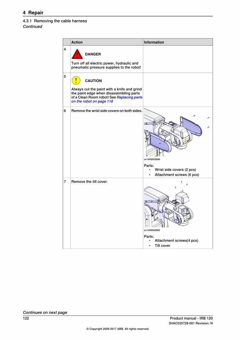
InformationAction
DANGER
Turn off all electric power, hydraulic andpneumatic pressure supplies to the robot!
4
CAUTION
Always cut the paint with a knife and grindthe paint edge when disassembling partsof a Clean Room robot! SeeReplacing partson the robot on page 118
5
xx1400002899
Remove thewrist side covers on both sides.6
Parts:• Wrist side covers (2 pcs)• Attachment screws (6 pcs)
xx1400002900
Remove the tilt cover.7
Parts:• Attachment screws(4 pcs)• Tilt cover
Continues on next page122 Product manual - IRB 120
3HAC035728-001 Revision: N© Copyright 2009-2017 ABB. All rights reserved.
4 Repair4.3.1 Removing the cable harnessContinued
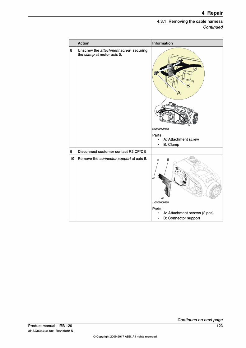
InformationAction
A
B
xx0900000912
Unscrew the attachment screw securingthe clamp at motor axis 5.
8
Parts:• A: Attachment screw• B: Clamp
Disconnect customer contact R2.CP/CS9
xx0900000888
Remove the connector support at axis 5.10
Parts:• A: Attachment screws (2 pcs)• B: Connector support
Continues on next pageProduct manual - IRB 120 1233HAC035728-001 Revision: N
© Copyright 2009-2017 ABB. All rights reserved.
4 Repair4.3.1 Removing the cable harness
Continued

InformationAction
xx0900000902
Remove the connector cover.11
Parts:• A: Attachment screw• B: Connector cover• C: Axis 5 shall be in 90° position
xx0900001000
Unscrew the attachment screw securing theclamp at motor axis 6.
12
Parts:• A: Attachment screw• B: Clamp
Disconnect connectors:• R2.MP5 and R2. ME5, motor axis 5• R2.MP6 and R2. ME6, motor axis 6.
13
Gently pull the cables from motor axis 5 andmotor axis 6 out of the wrist housing.
14
Continues on next page124 Product manual - IRB 120
3HAC035728-001 Revision: N© Copyright 2009-2017 ABB. All rights reserved.
4 Repair4.3.1 Removing the cable harnessContinued
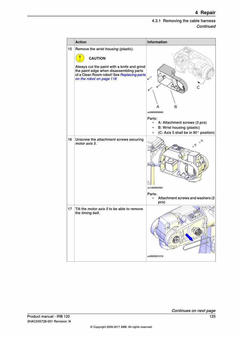
InformationAction
A B
C
xx0900000900
Remove the wrist housing (plastic).
CAUTION
Always cut the paint with a knife and grindthe paint edge when disassembling partsof a Clean Room robot! SeeReplacing partson the robot on page 118
15
Parts:• A: Attachment screws (3 pcs)• B: Wrist housing (plastic)• (C: Axis 5 shall be in 90° position)
xx1400002901
Unscrew the attachment screws securingmotor axis 5.
16
Parts:• Attachment screws and washers (2
pcs)
xx0900001019
Tilt the motor axis 5 to be able to removethe timing belt.
17
Continues on next pageProduct manual - IRB 120 1253HAC035728-001 Revision: N
© Copyright 2009-2017 ABB. All rights reserved.
4 Repair4.3.1 Removing the cable harness
Continued

InformationAction
xx1400002906
Carefully remove motor axis 5.18
Disconnect air hoses.19
Removing the cable harness in the upper arm housing
InformationAction
CAUTION
Always cut the paint with a knife and grindthe paint edge when disassembling partsof a Clean Room robot! SeeReplacing partson the robot on page 118
1
xx0900001018
Unscrew the two attachment screws secur-ing the cable harness in the bracket. Leavethe bracket fastened in the housing.
2
Parts:• A: Attachment screws (4 pcs)• B: Cable bracket• (C: Axis 5 shall be in 90° position)
Continues on next page126 Product manual - IRB 120
3HAC035728-001 Revision: N© Copyright 2009-2017 ABB. All rights reserved.
4 Repair4.3.1 Removing the cable harnessContinued

InformationAction
xx1400002909
Remove thehousing cover.3
Parts:• Housing cover• Attachment screws (8 pcs)
Carefully pull the cable harness out of thewrist housing to axis 4.
4
xx0900001023
Cut cable ties at cable bracket A.5
Parts:• A: Cable bracket• B: Cable bracket
Disconnect connectors:• R2.MP4• R2.ME4.
6
Continues on next pageProduct manual - IRB 120 1273HAC035728-001 Revision: N
© Copyright 2009-2017 ABB. All rights reserved.
4 Repair4.3.1 Removing the cable harness
Continued
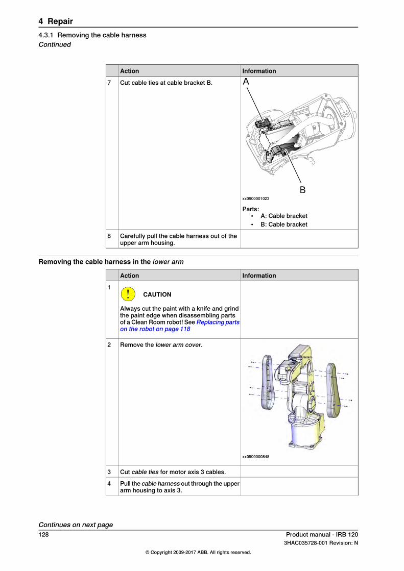
InformationAction
xx0900001023
Cut cable ties at cable bracket B.7
Parts:• A: Cable bracket• B: Cable bracket
Carefully pull the cable harness out of theupper arm housing.
8
Removing the cable harness in the lower arm
InformationAction
CAUTION
Always cut the paint with a knife and grindthe paint edge when disassembling partsof a Clean Room robot! SeeReplacing partson the robot on page 118
1
xx0900000848
Remove the lower arm cover.2
Cut cable ties for motor axis 3 cables.3
Pull the cable harness out through the upperarm housing to axis 3.
4
Continues on next page128 Product manual - IRB 120
3HAC035728-001 Revision: N© Copyright 2009-2017 ABB. All rights reserved.
4 Repair4.3.1 Removing the cable harnessContinued
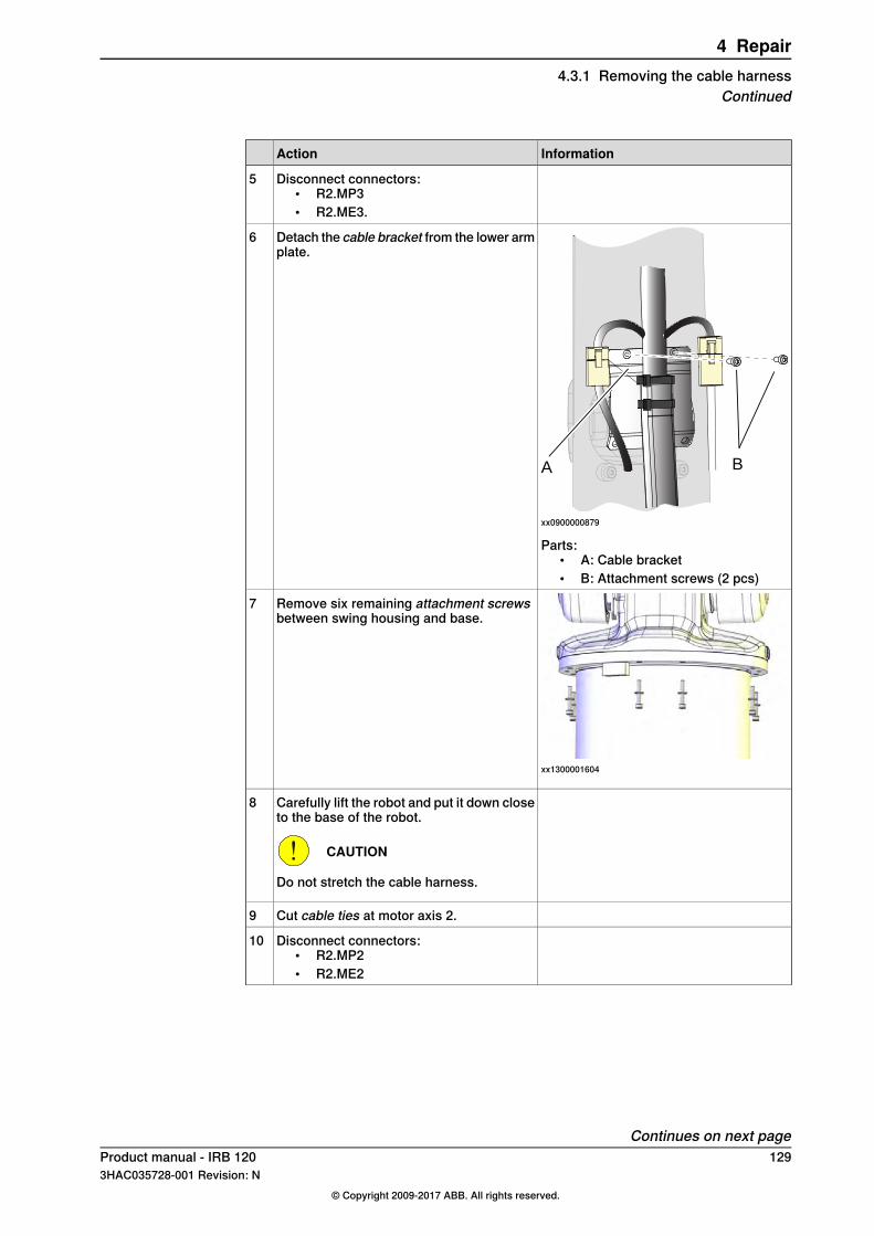
InformationAction
Disconnect connectors:• R2.MP3• R2.ME3.
5
A B
xx0900000879
Detach the cable bracket from the lower armplate.
6
Parts:• A: Cable bracket• B: Attachment screws (2 pcs)
xx1300001604
Remove six remaining attachment screwsbetween swing housing and base.
7
Carefully lift the robot and put it down closeto the base of the robot.
CAUTION
Do not stretch the cable harness.
8
Cut cable ties at motor axis 2.9
Disconnect connectors:• R2.MP2• R2.ME2
10
Continues on next pageProduct manual - IRB 120 1293HAC035728-001 Revision: N
© Copyright 2009-2017 ABB. All rights reserved.
4 Repair4.3.1 Removing the cable harness
Continued
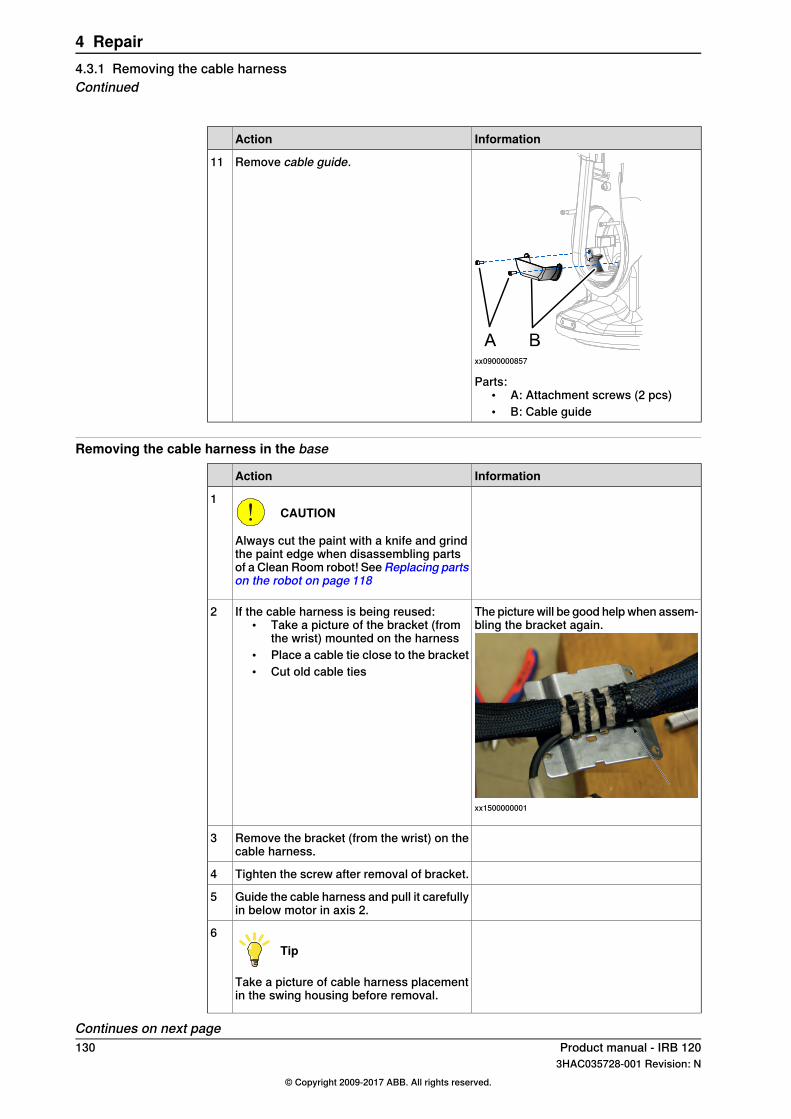
InformationAction
xx0900000857
Remove cable guide.11
Parts:• A: Attachment screws (2 pcs)• B: Cable guide
Removing the cable harness in the base
InformationAction
CAUTION
Always cut the paint with a knife and grindthe paint edge when disassembling partsof a Clean Room robot! SeeReplacing partson the robot on page 118
1
The picture will be good help when assem-bling the bracket again.
xx1500000001
If the cable harness is being reused:• Take a picture of the bracket (from
the wrist) mounted on the harness• Place a cable tie close to the bracket• Cut old cable ties
2
Remove the bracket (from the wrist) on thecable harness.
3
Tighten the screw after removal of bracket.4
Guide the cable harness and pull it carefullyin below motor in axis 2.
5
Tip
Take a picture of cable harness placementin the swing housing before removal.
6
Continues on next page130 Product manual - IRB 120
3HAC035728-001 Revision: N© Copyright 2009-2017 ABB. All rights reserved.
4 Repair4.3.1 Removing the cable harnessContinued
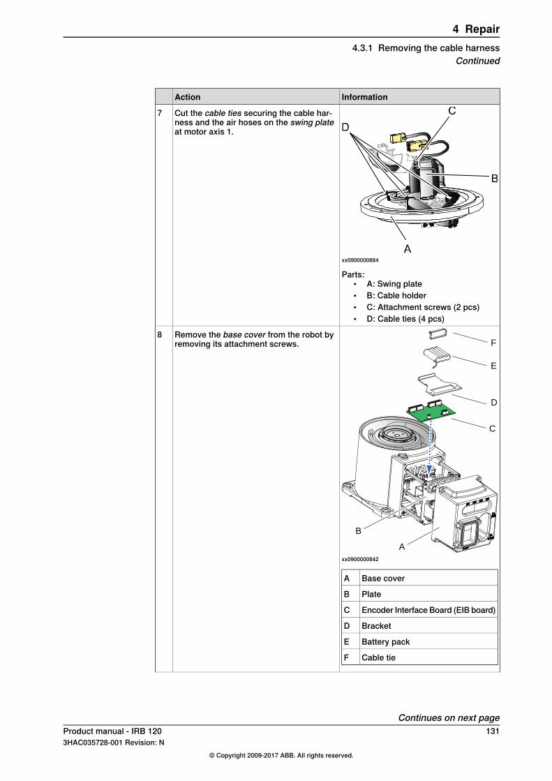
InformationAction
xx0900000884
Cut the cable ties securing the cable har-ness and the air hoses on the swing plateat motor axis 1.
7
Parts:• A: Swing plate• B: Cable holder• C: Attachment screws (2 pcs)• D: Cable ties (4 pcs)
C
D
E
F
A
B
xx0900000842
Base coverA
PlateB
Encoder Interface Board (EIB board)C
BracketD
Battery packE
Cable tieF
Remove the base cover from the robot byremoving its attachment screws.
8
Continues on next pageProduct manual - IRB 120 1313HAC035728-001 Revision: N
© Copyright 2009-2017 ABB. All rights reserved.
4 Repair4.3.1 Removing the cable harness
Continued
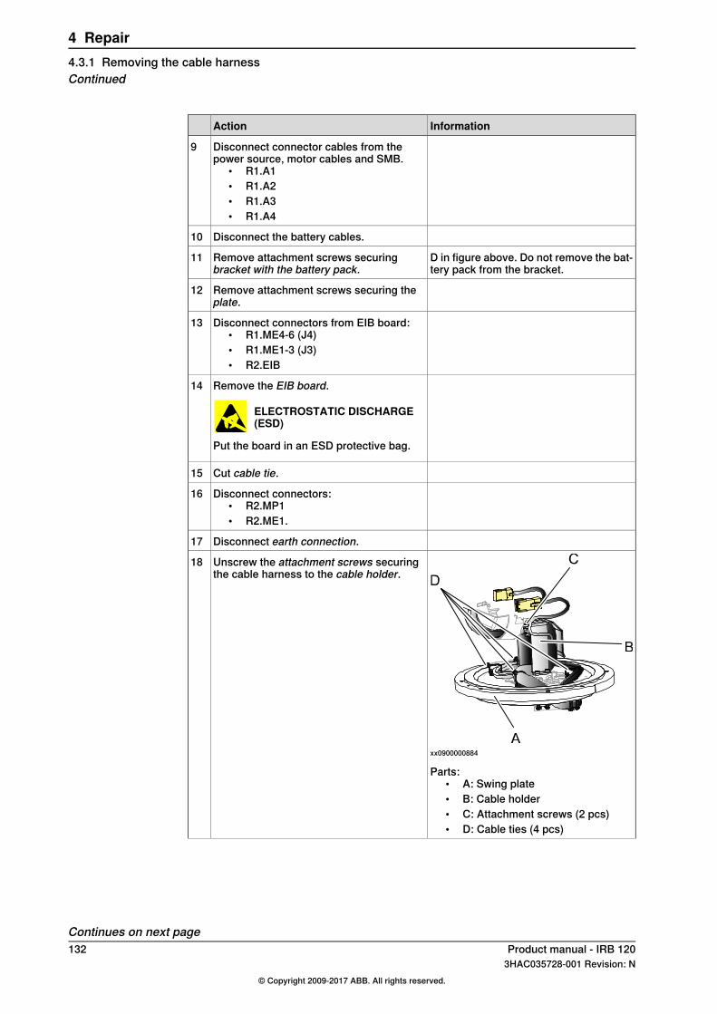
InformationAction
Disconnect connector cables from thepower source, motor cables and SMB.
• R1.A1• R1.A2• R1.A3• R1.A4
9
Disconnect the battery cables.10
D in figure above. Do not remove the bat-tery pack from the bracket.
Remove attachment screws securingbracket with the battery pack.
11
Remove attachment screws securing theplate.
12
Disconnect connectors from EIB board:• R1.ME4-6 (J4)• R1.ME1-3 (J3)• R2.EIB
13
Remove the EIB board.
ELECTROSTATIC DISCHARGE(ESD)
Put the board in an ESD protective bag.
14
Cut cable tie.15
Disconnect connectors:• R2.MP1• R2.ME1.
16
Disconnect earth connection.17
xx0900000884
Unscrew the attachment screws securingthe cable harness to the cable holder.
18
Parts:• A: Swing plate• B: Cable holder• C: Attachment screws (2 pcs)• D: Cable ties (4 pcs)
Continues on next page132 Product manual - IRB 120
3HAC035728-001 Revision: N© Copyright 2009-2017 ABB. All rights reserved.
4 Repair4.3.1 Removing the cable harnessContinued

InformationAction
CAUTION
Cable harness and hoses are sensitiveequipment. Use caution when handlingcable harness.
19
Carefully push and pull the complete cableharness past motor axis 1.
20
Product manual - IRB 120 1333HAC035728-001 Revision: N
© Copyright 2009-2017 ABB. All rights reserved.
4 Repair4.3.1 Removing the cable harness
Continued
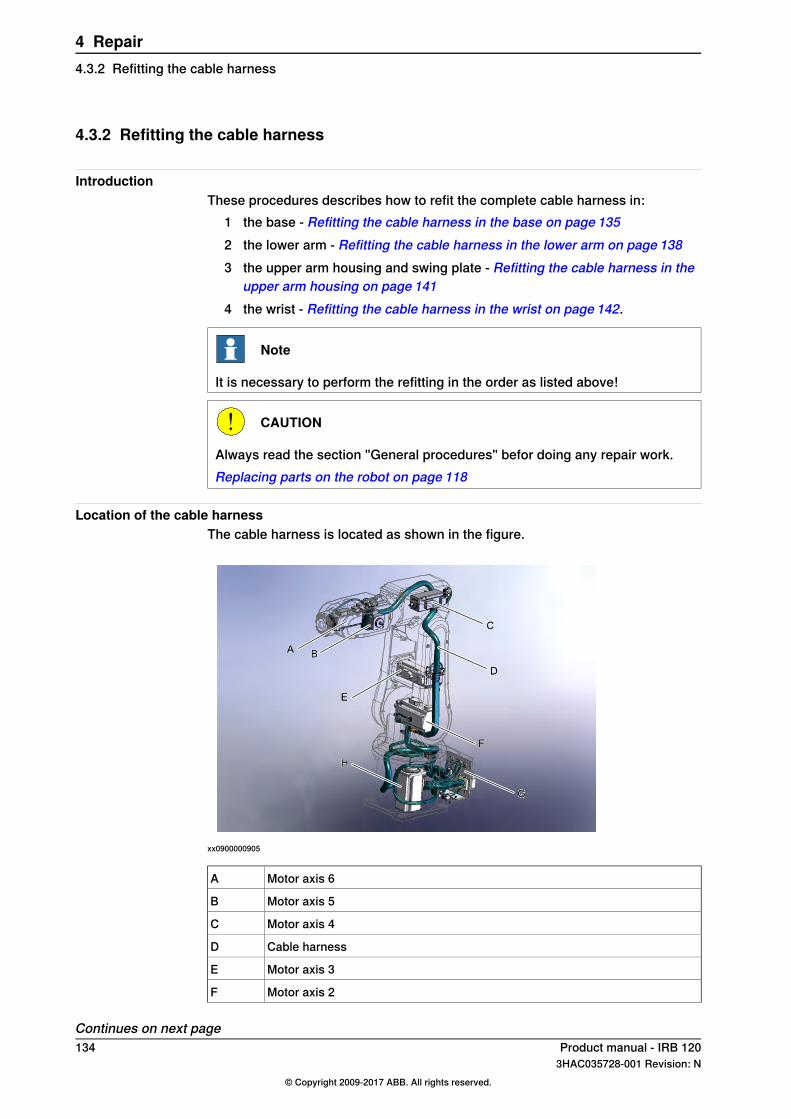
4.3.2 Refitting the cable harness
IntroductionThese procedures describes how to refit the complete cable harness in:
1 the base - Refitting the cable harness in the base on page 1352 the lower arm - Refitting the cable harness in the lower arm on page 1383 the upper arm housing and swing plate - Refitting the cable harness in the
upper arm housing on page 1414 the wrist - Refitting the cable harness in the wrist on page 142.
Note
It is necessary to perform the refitting in the order as listed above!
CAUTION
Always read the section "General procedures" befor doing any repair work.Replacing parts on the robot on page 118
Location of the cable harnessThe cable harness is located as shown in the figure.
xx0900000905
Motor axis 6A
Motor axis 5B
Motor axis 4C
Cable harnessD
Motor axis 3E
Motor axis 2F
Continues on next page134 Product manual - IRB 120
3HAC035728-001 Revision: N© Copyright 2009-2017 ABB. All rights reserved.
4 Repair4.3.2 Refitting the cable harness
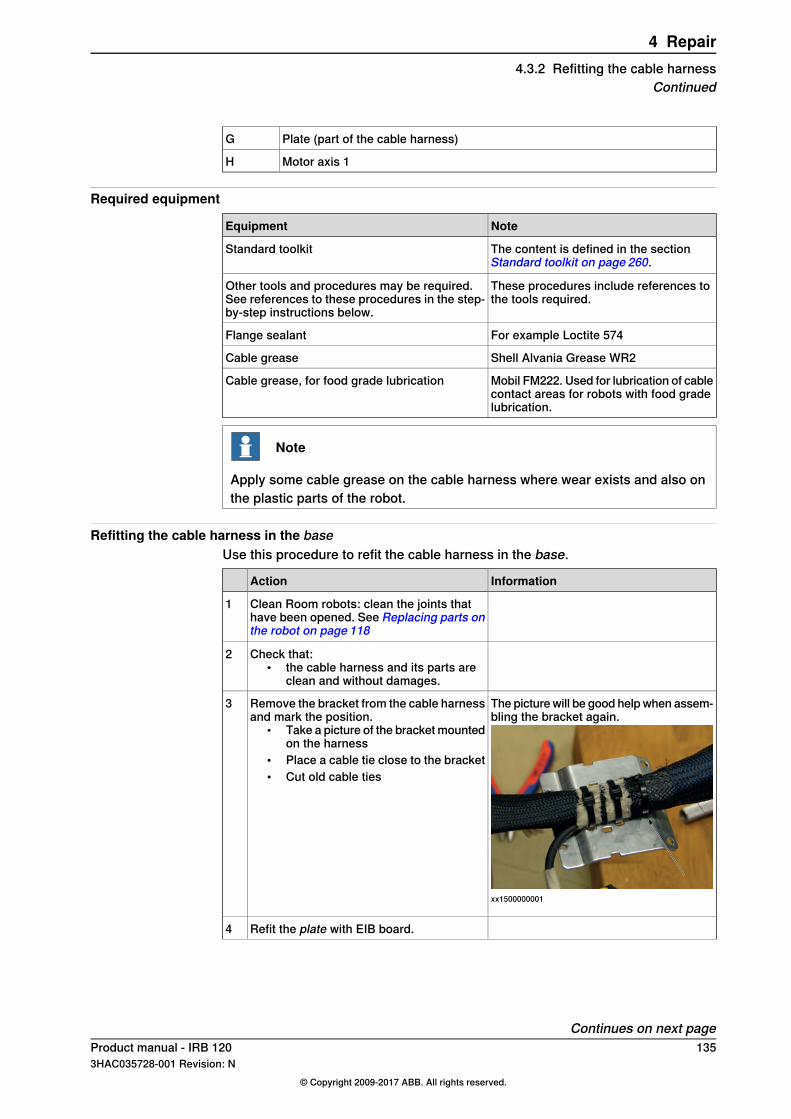
Plate (part of the cable harness)G
Motor axis 1H
Required equipment
NoteEquipment
The content is defined in the sectionStandard toolkit on page 260.
Standard toolkit
These procedures include references tothe tools required.
Other tools and procedures may be required.See references to these procedures in the step-by-step instructions below.
For example Loctite 574Flange sealant
Shell Alvania Grease WR2Cable grease
Mobil FM222. Used for lubrication of cablecontact areas for robots with food gradelubrication.
Cable grease, for food grade lubrication
Note
Apply some cable grease on the cable harness where wear exists and also onthe plastic parts of the robot.
Refitting the cable harness in the baseUse this procedure to refit the cable harness in the base.
InformationAction
Clean Room robots: clean the joints thathave been opened. See Replacing parts onthe robot on page 118
1
Check that:• the cable harness and its parts are
clean and without damages.
2
The picture will be good help when assem-bling the bracket again.
xx1500000001
Remove the bracket from the cable harnessand mark the position.
• Take a picture of the bracket mountedon the harness
• Place a cable tie close to the bracket• Cut old cable ties
3
Refit the plate with EIB board.4
Continues on next pageProduct manual - IRB 120 1353HAC035728-001 Revision: N
© Copyright 2009-2017 ABB. All rights reserved.
4 Repair4.3.2 Refitting the cable harness
Continued
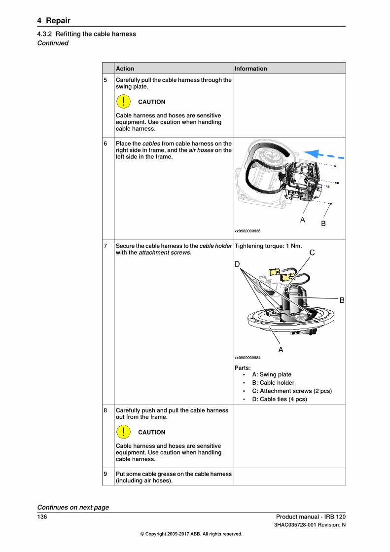
InformationAction
Carefully pull the cable harness through theswing plate.
CAUTION
Cable harness and hoses are sensitiveequipment. Use caution when handlingcable harness.
5
xx0900000836
Place the cables from cable harness on theright side in frame, and the air hoses on theleft side in the frame.
6
Tightening torque: 1 Nm.
xx0900000884
Secure the cable harness to the cable holderwith the attachment screws.
7
Parts:• A: Swing plate• B: Cable holder• C: Attachment screws (2 pcs)• D: Cable ties (4 pcs)
Carefully push and pull the cable harnessout from the frame.
CAUTION
Cable harness and hoses are sensitiveequipment. Use caution when handlingcable harness.
8
Put some cable grease on the cable harness(including air hoses).
9
Continues on next page136 Product manual - IRB 120
3HAC035728-001 Revision: N© Copyright 2009-2017 ABB. All rights reserved.
4 Repair4.3.2 Refitting the cable harnessContinued

InformationAction
Place the cable harness inside the cableholder.
10
xx1500000002
Loosen the cable bracket next to motor axis1.
11
Reconnect connectors:• R2.MP1• R2.ME1.
12
Secure the motor cables to the cablebracket with cable ties.
13
M3x8 (2 pcs)Fasten cable bracket.14
Är detta earth connection? Om inte, vadär det för kabel?
Refit the PE cable.15
Attachment screw (4 pcs) M3x8Refit the EIB board.
Note
Use ESD protective equipment.
16
Connect board.• R1.ME4-6 (J4)• R1.ME1-3 (J3)• R2.EIB.
17
Connect battery cables.18
Attachment screw (4 pcs) M3x8Refit the battery plate.19
Attachment screw (4 pcs) M3x8Refit the EIB plate.
CAUTION
Cables are sensitive equipment. Use cautionwhen handling cables.
20
Continues on next pageProduct manual - IRB 120 1373HAC035728-001 Revision: N
© Copyright 2009-2017 ABB. All rights reserved.
4 Repair4.3.2 Refitting the cable harness
Continued

InformationAction
Tightening torque: 4 Nm
A B
xx0900000829
Refit the base cover.21
Clean Room robots: seal and paint the jointsthat have been opened. SeeReplacing partson the robot on page 118
Note
After all repair work, wipe the robot free fromparticles with spirit on a lint free cloth.
22
Refitting the cable harness in the lower arm
InformationAction
Clean Room robots: clean the joints thathave been opened. See Replacing parts onthe robot on page 118
1
Place the cable harness in the holder on theswing plate.
• Put cable R2.MP2 towards back• Put cable R2.ME2 towards front
2
Attachment screw M3x8 (2 pcs)Tighten screws in bracket.3
Secure air hoses on the swing plate withcable ties.
4
Secure the cable harness on the swing platewith cable ties.
5
xx1500000003
Put cable ties on the motor connections toease the mounting in axis-2 motor.
6
Continues on next page138 Product manual - IRB 120
3HAC035728-001 Revision: N© Copyright 2009-2017 ABB. All rights reserved.
4 Repair4.3.2 Refitting the cable harnessContinued
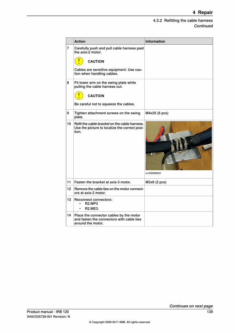
InformationAction
Carefully push and pull cable harness pastthe axis-2 motor.
CAUTION
Cables are sensitive equipment. Use cau-tion when handling cables.
7
Fit lower arm on the swing plate whilepulling the cable harness out.
CAUTION
Be careful not to squeeze the cables.
8
M4x25 (6 pcs)Tighten attachment screws on the swingplate.
9
xx1500000001
Refit the cable bracket on the cable harness.Use the picture to localize the correct posi-tion.
10
M3x8 (2 pcs)Fasten the bracket at axis-3 motor.11
Remove the cable ties on the motor connect-ors at axis-2 motor.
12
Reconnect connectors:• R2.MP3• R2.ME3.
13
Place the connector cables by the motorand fasten the connectors with cable tiesaround the motor.
14
Continues on next pageProduct manual - IRB 120 1393HAC035728-001 Revision: N
© Copyright 2009-2017 ABB. All rights reserved.
4 Repair4.3.2 Refitting the cable harness
Continued

InformationAction
Tightening torque: 1 Nm.
xx0900000857
Fit the cable guide.
CAUTION
The plastic will crack if screws are tightenedtoo hard.
15
Parts:• A: Attachment screws (2 pcs)• B: Cable guide
Reconnect the motor connections, axis-3motor
• R2.ME3• R2.MP3.
16
Fasten motor cables with cable ties on thecable bracket.
17
Tightening torque: 1 Nm.
A B
xx0900000879
Fit the cable bracket to the lower arm plate.18
Parts:• A: Cable bracket• B: Attachment screws (2 pcs)
Pull the cable harness through the upperarm housing.
19
Verify that the cable harness is not twisted.20
Continues on next page140 Product manual - IRB 120
3HAC035728-001 Revision: N© Copyright 2009-2017 ABB. All rights reserved.
4 Repair4.3.2 Refitting the cable harnessContinued
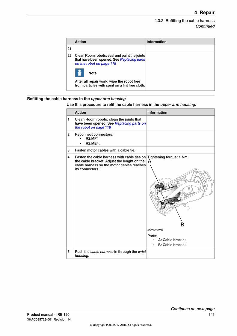
InformationAction
21
Clean Room robots: seal and paint the jointsthat have been opened. SeeReplacing partson the robot on page 118
Note
After all repair work, wipe the robot freefrom particles with spirit on a lint free cloth.
22
Refitting the cable harness in the upper arm housingUse this procedure to refit the cable harness in the upper arm housing.
InformationAction
Clean Room robots: clean the joints thathave been opened. See Replacing parts onthe robot on page 118
1
Reconnect connectors:• R2.MP4• R2.ME4.
2
Fasten motor cables with a cable tie.3
Tightening torque: 1 Nm.
xx0900001023
Fasten the cable harness with cable ties onthe cable bracket. Adjust the lenght on thecable harness so the motor cables reachesits connectors.
4
Parts:• A: Cable bracket• B: Cable bracket
Push the cable harness in through the wristhousing.
5
Continues on next pageProduct manual - IRB 120 1413HAC035728-001 Revision: N
© Copyright 2009-2017 ABB. All rights reserved.
4 Repair4.3.2 Refitting the cable harness
Continued

InformationAction
Tightening torque: 1 Nm.
xx0900001018
Refit the cable bracket in the housing withits attachment screws.
6
Parts:• A: Attachment screws (2 pcs)• B: Cable bracket
Clean Room robots: seal and paint the jointsthat have been opened. SeeReplacing partson the robot on page 118
Note
After all repair work, wipe the robot free fromparticles with spirit on a lint free cloth.
7
Refitting the cable harness in the wristUse this procedure to refit the cable harness in the wrist.
InformationAction
Clean Room robots: clean the joints thathave been opened. See Replacing parts onthe robot on page 118
1
Reconnect air hoses. Put them flat to makeroom for the motor.
2
Reconnect customer contact R2.CS3
Place the motor in axis 5.4
Refit the timing belt.5
M5x16 (2 pcs) and washersFasten the motor just enough to still be ableto move the motor.
6
Tip
Use a tension scale to have the correcttorque.
Tension the timing belt to 7.6 - 8.4 Nm.7
Tightening torque: 5.5 NmTighten motor attachment screws.8
Continues on next page142 Product manual - IRB 120
3HAC035728-001 Revision: N© Copyright 2009-2017 ABB. All rights reserved.
4 Repair4.3.2 Refitting the cable harnessContinued

InformationAction
Tightening torque: 2 Nm
A B
C
xx0900000900
Refit the wrist housing (plastic).9
• A: Attachment screws, M3x25 (3pcs)
• B: Wrist housing (plastic)• C: (Axis 5 shall be in 90° position)
Reconnect connectors:• R2.MP5• R2.ME5.
10
Put the cables around the motor.11
Tightening torque: 1 Nm.
xx0900000888
Refit connector support (plastic).12
Parts:• A: Attachment screws, M3x8 (2
pcs)• B: Connector support (plastic)
Fasten cables to axis 6 in the connectorsupport.
13
Continues on next pageProduct manual - IRB 120 1433HAC035728-001 Revision: N
© Copyright 2009-2017 ABB. All rights reserved.
4 Repair4.3.2 Refitting the cable harness
Continued
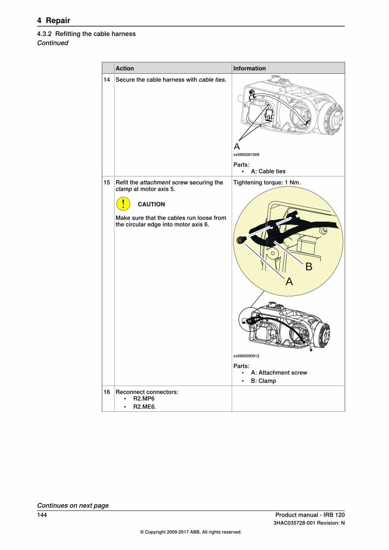
InformationAction
xx0900001009
Secure the cable harness with cable ties.14
Parts:• A: Cable ties
Tightening torque: 1 Nm.
A
B
xx0900000912
Refit the attachment screw securing theclamp at motor axis 5.
CAUTION
Make sure that the cables run loose fromthe circular edge into motor axis 6.
15
Parts:• A: Attachment screw• B: Clamp
Reconnect connectors:• R2.MP6• R2.ME6.
16
Continues on next page144 Product manual - IRB 120
3HAC035728-001 Revision: N© Copyright 2009-2017 ABB. All rights reserved.
4 Repair4.3.2 Refitting the cable harnessContinued

InformationAction
Tightening torque: 1 Nm.
xx0900001000
Refit the attachment screw securing theclamp at motor axis 6.
17
Parts:• A: Attachment screw• B: Clamp
Tightening torque: 1 Nm.
xx0900000902
Refit the connector cover.18
Parts:• A: Attachment screw M3x8 (1 pcs)• B: Connector cover• C: (Axis 5 shall be in 90° position)
Put cable grease on the cable harness inthe wrist.
19
Clean all the covers if they are dirty.20
Put cable grease inside the covers.21
Continues on next pageProduct manual - IRB 120 1453HAC035728-001 Revision: N
© Copyright 2009-2017 ABB. All rights reserved.
4 Repair4.3.2 Refitting the cable harness
Continued

InformationAction
Tightening torque: 1 Nm.Refit the wrist side covers.22Attachment screw M3x8 (3 pcs)
Tightening torque: 1 Nm.
A
B
Cxx0900000901
Refit the tilt cover.23
Parts:• A: Attachment screw M3x8 (4 pcs)• B: Tilt cover• C: Motor axis 6
Put cable grease on the sleeve in axis 4.24
Tightening torque: 1 NmRefit the housing cover at axis 4.• housing cover and• lower arm cover.
25Attachment screw M3x8 (8 pcs)
Put cable grease on the cable harness andsleeve in lower arm.
26
Tightening torque: 1 NmRefit the lower arm cover at axis 4.27Attachment screw M3x8 (4 pcs)
Connect the robot to the power source.
DANGER
Make sure all safety requirements are metwhen performing the first test run. Theseare further detailed in the section DANGER- First test run may cause injury or damage!on page 47.
28
Jog the robot to 90° in axis 1.29
Fasten the two remaining screws at swingplate/base.
30
Continues on next page146 Product manual - IRB 120
3HAC035728-001 Revision: N© Copyright 2009-2017 ABB. All rights reserved.
4 Repair4.3.2 Refitting the cable harnessContinued
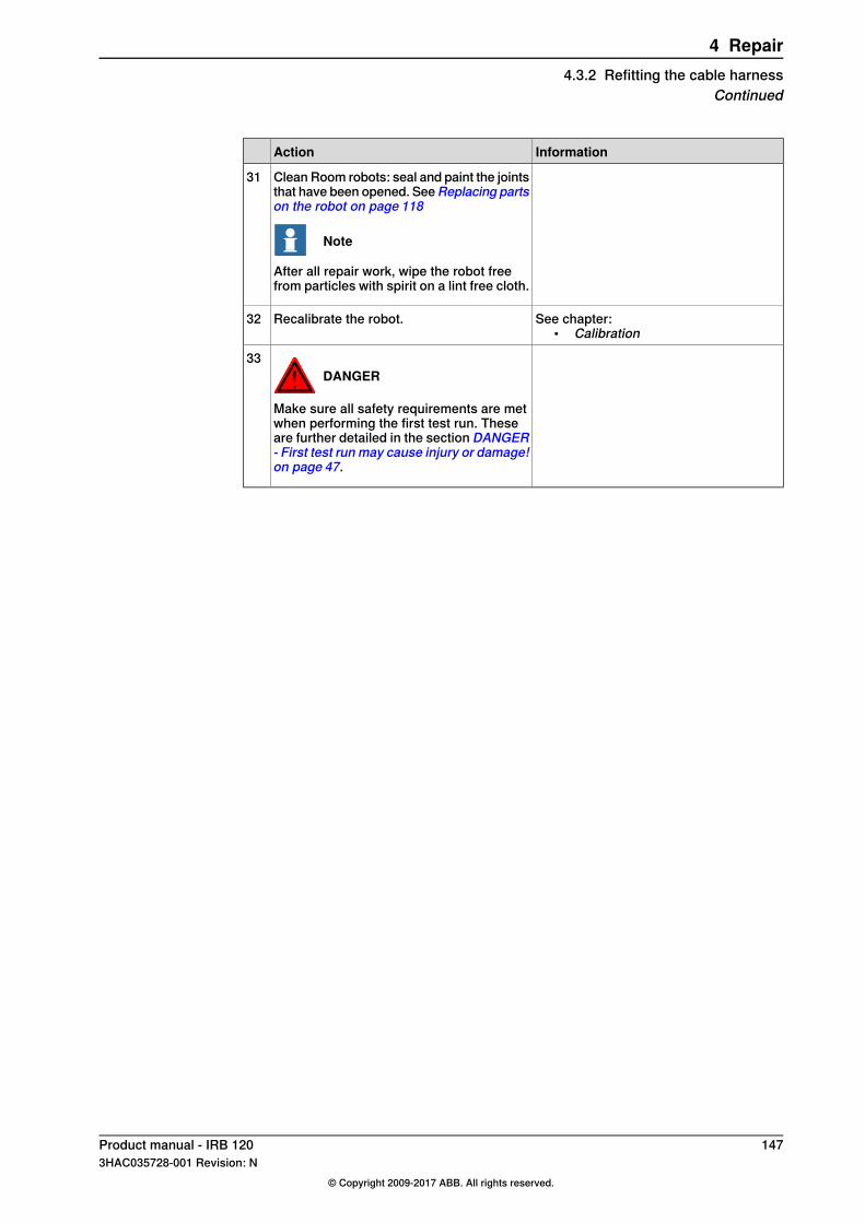
InformationAction
Clean Room robots: seal and paint the jointsthat have been opened. SeeReplacing partson the robot on page 118
Note
After all repair work, wipe the robot freefrom particles with spirit on a lint free cloth.
31
See chapter:• Calibration
Recalibrate the robot.32
DANGER
Make sure all safety requirements are metwhen performing the first test run. Theseare further detailed in the section DANGER- First test run may cause injury or damage!on page 47.
33
Product manual - IRB 120 1473HAC035728-001 Revision: N
© Copyright 2009-2017 ABB. All rights reserved.
4 Repair4.3.2 Refitting the cable harness
Continued

4.3.3 Replacing the Encoder Interface board
IntroductionThis procedure describes how to replace the Encoder Interface board.
Location of the Encoder Interface board
C
D
E
F
A
B
xx0900000842
Base coverA
PlateB
Encoder Interface Board (EIB board)C
BracketD
Battery packE
Cable strapF
Required equipment
NoteEquipment
The content is defined in the sectionStandardtoolkit on page 260.
Standard tools
These procedures include references to thetools required.
Other tools and procedures may be required.See references to these procedures in thestep-by-step instructions below.
Continues on next page148 Product manual - IRB 120
3HAC035728-001 Revision: N© Copyright 2009-2017 ABB. All rights reserved.
4 Repair4.3.3 Replacing the Encoder Interface board

Removing the EIB boardUse this procedure to remove the EIB board.
InformationAction
DANGER
Turn off all electric power, hydraulic andpneumatic pressure supplies to the robot!
1
CAUTION
Always cut the paint with a knife and grindthe paint edge when disassembling partsof a Clean Room robot! SeeReplacing partson the robot on page 118
2
See the figure in :• Location of the Encoder Interface
board on page 148
Remove the base cover.3
See the figure in:• Location of the Encoder Interface
board on page 148
Remove the attachment screws securingthe plate.
4
Pull carefully out the cable harnesss maina little in order to reach the EIB board.
5
Disconnect the battery cable.6
See the figure in:• Location of the Encoder Interface
board on page 148
Remove the bracket where the battery isfitted.
7
Disconnect connectors:• R1.ME1-3• R1.ME4-6• R2.EIB.
8
See the figure in:• Location of the Encoder Interface
board on page 148
Remove the EIB board.9
Refitting the EIB boardUse this procedure to refit the EIB board.
InformationAction
Clean Room robots: clean the joints thathave been opened. See Replacing parts onthe robot on page 118
1
Tightening torque: 2 Nm.Fit the EIB board.2See the figure in:
• Location of the Encoder Interfaceboard on page 148
Reconnect connectors:• R1.ME1-3• R1.ME4-6• R2.EIB.
3
Continues on next pageProduct manual - IRB 120 1493HAC035728-001 Revision: N
© Copyright 2009-2017 ABB. All rights reserved.
4 Repair4.3.3 Replacing the Encoder Interface board
Continued
InformationAction
See the figure in:• Location of the Encoder Interface
board on page 148
Fit the plate where the battery is fitted.4
Reconnect the battery cable.5
CAUTION
Arrange the cable harness inside correctlyin a way that:
• it is not damaged in the continuedrefitting process
• extra wear will not occur after pro-duction is restarted, which willshorten the life of the harness.
See section• Refitting the cable harness on
page 134.
Push the cable harness main carefully intothe base.
6
Tightening torque: 2 Nm.Secure the platewith its attachment screws.7See the figure in:
• Location of the Encoder Interfaceboard on page 148
Tightening torque: 4 Nm.Refit the base cover.8See the figure in:
• Location of the Encoder Interfaceboard on page 148
Clean Room robots: seal and paint the jointsthat have been opened. SeeReplacing partson the robot on page 118
Note
After all repair work, wipe the robot freefrom particles with spirit on a lint free cloth.
9
See chapter:• Calibration on page 225
Recalibrate the robot.10
DANGER
Make sure all safety requirements are metwhen performing the first test run. Theseare further detailed in the section DANGER- First test run may cause injury or damage!on page 47.
11
150 Product manual - IRB 1203HAC035728-001 Revision: N
© Copyright 2009-2017 ABB. All rights reserved.
4 Repair4.3.3 Replacing the Encoder Interface boardContinued
4.4 Plastic covers
4.4.1 Replacing plastic covers
IntroductionThe section describes how to replace the plastic covers on the robot.
CAUTION
Always read the section "General procedures" before doing any repair work.Replacing parts on the robot on page 118
Continues on next pageProduct manual - IRB 120 1513HAC035728-001 Revision: N
© Copyright 2009-2017 ABB. All rights reserved.
4 Repair4.4.1 Replacing plastic covers
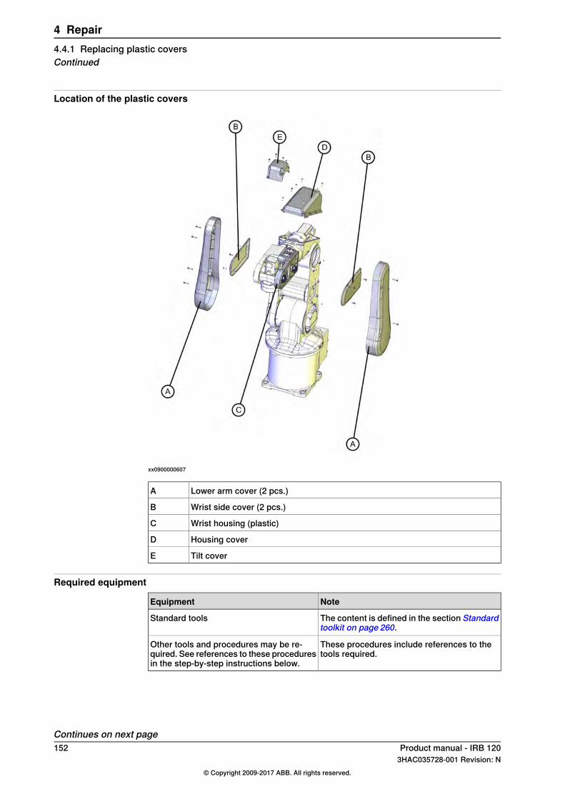
Location of the plastic covers
xx0900000607
Lower arm cover (2 pcs.)A
Wrist side cover (2 pcs.)B
Wrist housing (plastic)C
Housing coverD
Tilt coverE
Required equipment
NoteEquipment
The content is defined in the section Standardtoolkit on page 260.
Standard tools
These procedures include references to thetools required.
Other tools and procedures may be re-quired. See references to these proceduresin the step-by-step instructions below.
Continues on next page152 Product manual - IRB 120
3HAC035728-001 Revision: N© Copyright 2009-2017 ABB. All rights reserved.
4 Repair4.4.1 Replacing plastic coversContinued

Attachment screws and tightening torquesThe table shows what attachment screws and tightening torques to be used.
Tighteningtorque
Qty.Screw qualityAttachmentscrew
Cover
1 Nm4+4Steel 12.9 Black oxideM3x16Lower arm cover
1 Nm3+3Steel 12.9 Black oxideM3x8Wrist side cover
1 Nm3Steel 12.9 Black oxideM3x25Wrist housing (plastic)
1 Nm8Steel 12.9 Black oxideM3x8Housing cover
1 Nm4Steel 12.9 Black oxideM3x8Tilt cover
Removing plastic coversUse this procedure to remove the plastic covers.
InformationAction
DANGER
Turn off all electric power, hydraulic andpneumatic pressure supplies to the robot!
1
CAUTION
Always cut the paint with a knife and grind thepaint edge when disassembling parts of aClean Room robot! See Replacing parts on therobot on page 118
2
Remove the attachment screws securing theplastic cover.
3
Remove the plastic cover.4
If the cover shall be reused, keep it clean andput in a safe place.
5
Refitting plastic coversUse this procedure to refit the plastic covers.
InformationAction
Clean Room robots: clean the joints that havebeen opened. SeeReplacing parts on the roboton page 118
1
If the plastic cover is cracked or hasany other damage it must be replacedwith a new one.
Before fitting the plastic cover, check it forcracks or any other damage.
2
Fit the plastic cover and secure it with its attach-ment screws.
3
Which attachment screws to use is describedin the table:
• Attachment screws and tighteningtorques on page 153
Continues on next pageProduct manual - IRB 120 1533HAC035728-001 Revision: N
© Copyright 2009-2017 ABB. All rights reserved.
4 Repair4.4.1 Replacing plastic covers
Continued
InformationAction
For tightening torques, see the table:• Attachment screws and tightening
torques on page 153
4
Clean Room robots: seal and paint the jointsthat have been opened. See Replacing partson the robot on page 118
Note
After all repair work, wipe the robot free fromparticles with spirit on a lint free cloth.
5
154 Product manual - IRB 1203HAC035728-001 Revision: N
© Copyright 2009-2017 ABB. All rights reserved.
4 Repair4.4.1 Replacing plastic coversContinued

4.5 Upper arm
4.5.1 Replacing the upper arm
IntroductionThis procedure describes how to replace the upper arm.
CAUTION
Always read the section "General procedures" befor doing any repair work.Replacing parts on the robot on page 118
Location of upper armThe upper and lower arms are located as shown in the figure.
xx0900000924
Upper arm, complete with wristA
Continues on next pageProduct manual - IRB 120 1553HAC035728-001 Revision: N
© Copyright 2009-2017 ABB. All rights reserved.
4 Repair4.5.1 Replacing the upper arm
Attachment screws (16 pcs)B
Gearbox, axis 3C
Lower armD
Required equipment
NoteEquipment
The content is defined in the section Standardtoolkit on page 260.
Standard toolkit
These procedures include references to the toolsrequired.
Other tools and procedures may be re-quired. See references to these proced-ures in the step-by-step instructions be-low.
For removing residues of Loctite.Loctite 7063
Loctite 574
Removing the upper armUse this procedure to remove the upper arm.
InformationAction
Move axis 5 to a 90° position.1
DANGER
Turn off all electric power, hydraulic andpneumatic pressure supplies to the robot!
2
CAUTION
Always cut the paint with a knife and grindthe paint edge when disassembling partsof a Clean Room robot! SeeReplacing partson the robot on page 118
3
Continues on next page156 Product manual - IRB 120
3HAC035728-001 Revision: N© Copyright 2009-2017 ABB. All rights reserved.
4 Repair4.5.1 Replacing the upper armContinued

InformationAction
A
B
C
B
xx0900000999
Remove the wrist covers.4
Parts:• A: Wrist covers (2 pcs)• B: Attachment screws (3+3 pcs)• C: Axis 5 shall be in 90° position
See section• Replacingmotor axis 5 on page211
Remove motor axis 5.5
See section• Removing the cable harness on
page 120.
Remove the cable harness in the wrist.6
Pull the cable harness out of the wristhousing.
7
A B
C
xx0900000900
Remove the wrist housing (plastic).8
Parts:• A: Attachment screws (3 pcs)• B: Wrist housing (plastic)• C: Axis 5 shall be in 90° position
See section• Removing the cable harness on
page 120.
Remove the cable harness in the upper armhousing.
9
Continues on next pageProduct manual - IRB 120 1573HAC035728-001 Revision: N
© Copyright 2009-2017 ABB. All rights reserved.
4 Repair4.5.1 Replacing the upper arm
Continued

InformationAction
xx0900001023
Unscrew the attachment screws securingthe cable brackets on both sides of motoraxis 4.
10
Parts:• A: Cable bracket• B: Cable bracket
xx0900000848
Remove the lower arm covers on both sidesof the robot.
11
See section• Removing the cable harness on
page 120.
Remove the cable harness in the lower arm.12
Continues on next page158 Product manual - IRB 120
3HAC035728-001 Revision: N© Copyright 2009-2017 ABB. All rights reserved.
4 Repair4.5.1 Replacing the upper armContinued

InformationAction
xx0900000851
Unscrew the attachment screws securingthe lower arm plate to the motor cover.
13
Parts:• A: Cable harness• B: Lower arm plate• C: Motor cover• D: Attachment screws (4 pcs)• E: Holes for attachment screws (4
pcs)• F: Cable guide
Pull out the cable harness through the upperarm housing.
14
Secure the upper arm by holding it firmly.15
See the figure in:• Location of upper arm on page155
Unscrew the attachment screws securingthe upper arm with wrist to gearbox axis 3.
16
Remove the upper arm.17
Refitting the upper armUse this procedure to refit the upper arm.
InformationAction
Clean Room robots: clean the joints thathave been opened. See Replacing parts onthe robot on page 118
1
Check that:• All assembly surfaces are clean and
without damages.
2
SeeReplacing the upper arm on page155.• Required equipment on page 156
Remove old residues of Loctite from theassembly surfaces on gearbox axis 3 andupper arm, using Loctite 7063.
3
Apply Loctite 574 on the assembly surfaceson gearbox axis 3 and the upper arm.
4
Continues on next pageProduct manual - IRB 120 1593HAC035728-001 Revision: N
© Copyright 2009-2017 ABB. All rights reserved.
4 Repair4.5.1 Replacing the upper arm
Continued
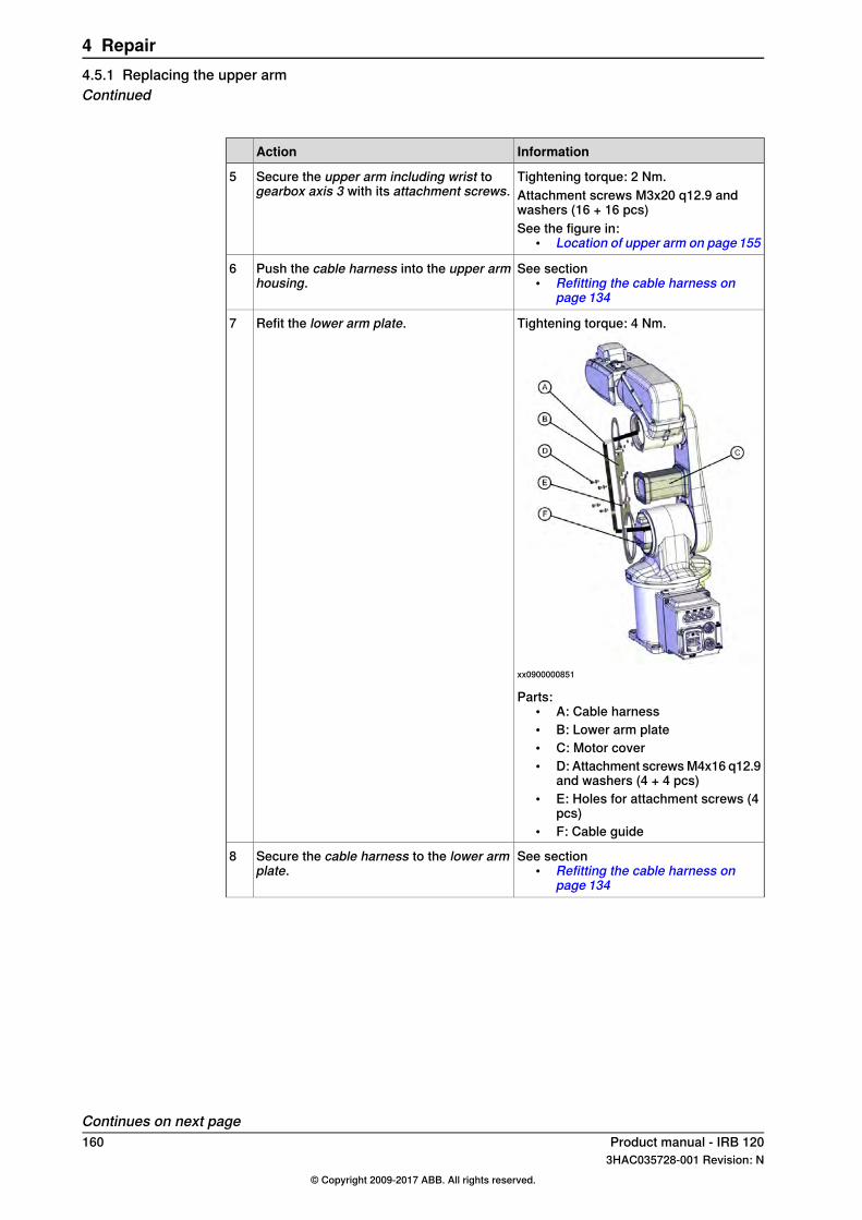
InformationAction
Tightening torque: 2 Nm.Secure the upper arm including wrist togearbox axis 3 with its attachment screws.
5Attachment screws M3x20 q12.9 andwashers (16 + 16 pcs)See the figure in:
• Location of upper arm on page155
See section• Refitting the cable harness on
page 134
Push the cable harness into the upper armhousing.
6
Tightening torque: 4 Nm.
xx0900000851
Refit the lower arm plate.7
Parts:• A: Cable harness• B: Lower arm plate• C: Motor cover• D: Attachment screws M4x16 q12.9
and washers (4 + 4 pcs)• E: Holes for attachment screws (4
pcs)• F: Cable guide
See section• Refitting the cable harness on
page 134
Secure the cable harness to the lower armplate.
8
Continues on next page160 Product manual - IRB 120
3HAC035728-001 Revision: N© Copyright 2009-2017 ABB. All rights reserved.
4 Repair4.5.1 Replacing the upper armContinued

InformationAction
Tightening torque: 1 Nm.
xx0900000848
Refit the lower arm covers.9
See section• Refitting the cable harness on
page 134
Secure the cable harness in the upper armhousing.
10
Tightening torque: 1 Nm.
xx0900001023
Refit the two cable brackets on either sideof motor axis 4.
11
Parts:• A: Cable bracket• B: Cable bracket
Push the cable harness into the wrist.12
Continues on next pageProduct manual - IRB 120 1613HAC035728-001 Revision: N
© Copyright 2009-2017 ABB. All rights reserved.
4 Repair4.5.1 Replacing the upper arm
Continued
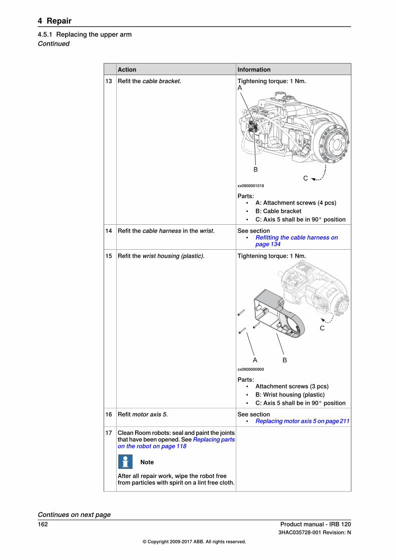
InformationAction
Tightening torque: 1 Nm.
xx0900001018
Refit the cable bracket.13
Parts:• A: Attachment screws (4 pcs)• B: Cable bracket• C: Axis 5 shall be in 90° position
See section• Refitting the cable harness on
page 134
Refit the cable harness in the wrist.14
Tightening torque: 1 Nm.
A B
C
xx0900000900
Refit the wrist housing (plastic).15
Parts:• Attachment screws (3 pcs)• B: Wrist housing (plastic)• C: Axis 5 shall be in 90° position
See section• Replacingmotor axis 5 on page211
Refit motor axis 5.16
Clean Room robots: seal and paint the jointsthat have been opened. SeeReplacing partson the robot on page 118
Note
After all repair work, wipe the robot freefrom particles with spirit on a lint free cloth.
17
Continues on next page162 Product manual - IRB 120
3HAC035728-001 Revision: N© Copyright 2009-2017 ABB. All rights reserved.
4 Repair4.5.1 Replacing the upper armContinued
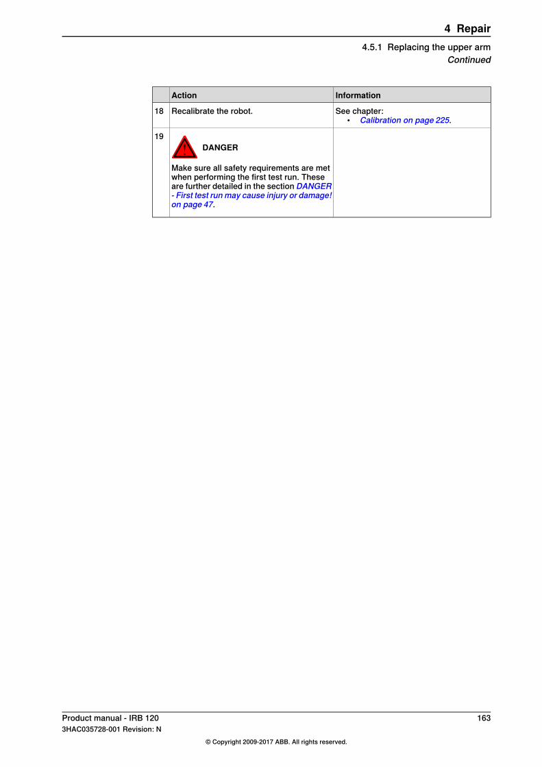
InformationAction
See chapter:• Calibration on page 225.
Recalibrate the robot.18
DANGER
Make sure all safety requirements are metwhen performing the first test run. Theseare further detailed in the section DANGER- First test run may cause injury or damage!on page 47.
19
Product manual - IRB 120 1633HAC035728-001 Revision: N
© Copyright 2009-2017 ABB. All rights reserved.
4 Repair4.5.1 Replacing the upper arm
Continued
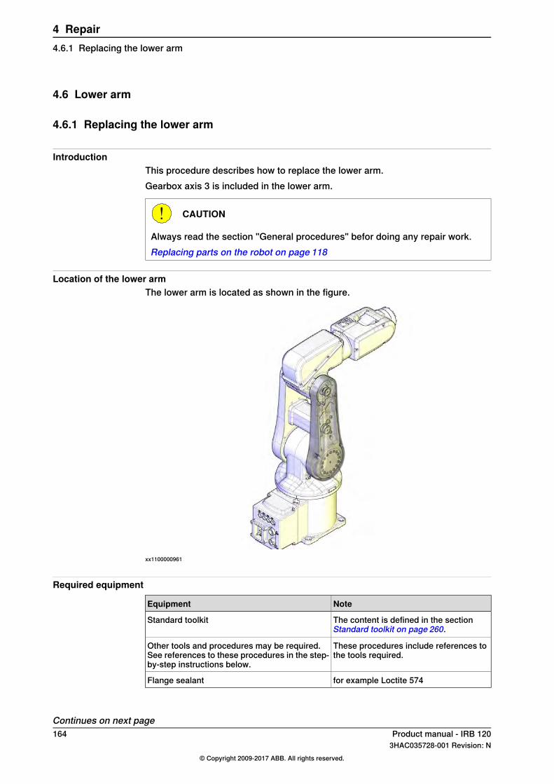
4.6 Lower arm
4.6.1 Replacing the lower arm
IntroductionThis procedure describes how to replace the lower arm.Gearbox axis 3 is included in the lower arm.
CAUTION
Always read the section "General procedures" befor doing any repair work.Replacing parts on the robot on page 118
Location of the lower armThe lower arm is located as shown in the figure.
xx1100000961
Required equipment
NoteEquipment
The content is defined in the sectionStandard toolkit on page 260.
Standard toolkit
These procedures include references tothe tools required.
Other tools and procedures may be required.See references to these procedures in the step-by-step instructions below.
for example Loctite 574Flange sealant
Continues on next page164 Product manual - IRB 120
3HAC035728-001 Revision: N© Copyright 2009-2017 ABB. All rights reserved.
4 Repair4.6.1 Replacing the lower arm

Removing the lower armUse this procedure to remove the lower arm.
InformationAction
DANGER
Turn off all electric power, hydraulic andpneumatic pressure supplies to the robot!
1
CAUTION
Always cut the paint with a knife and grindthe paint edge when disassembling partsof a Clean Room robot! SeeReplacing partson the robot on page 118
2
xx0900000848
Remove the lower arm covers on bothsides of the robot.
3
See section• Removing the cable harness in the
wrist on page 121
Remove the cable harness in the lower arm.4
Unscrew the attachment screws securingthe lower and upper arms and separate thetwo.
5
Unscrew the attachment screws securingthe motor cover to the lower arm plate.
6
Continues on next pageProduct manual - IRB 120 1653HAC035728-001 Revision: N
© Copyright 2009-2017 ABB. All rights reserved.
4 Repair4.6.1 Replacing the lower arm
Continued

InformationActionAA BB
CC DD
xx0900000859
Unscrew the attachment screws securingthe lower arm to axis-2 gearbox.
7
Parts:• A: Swing housing• B: Gearbox axis 2• C: Lower arm• D: Attachment screws (16 pcs)
Remove the lower arm.8
See section• Replacing axis-3 motor with gear-
box on page 202
Remove axis-3 motor and timing belt.9
Refitting the lower armUse this procedure to refit the lower arm.
InformationAction
Clean Room robots: clean the joints thathave been opened. See Replacing parts onthe robot on page 118
1
Check that:• all assembly surfaces are clean and
without damages.
2
SeeReplacing the lower arm on page164.• Required equipment on page 164
Remove old residues of Loctite from theassembly surfaces on gearbox axis 2 andlower arm, using Loctite 7063.
3
Apply flange sealant on the assembly sur-faces on axis-2 gearbox and lower arm.
4
xx1700000766
Remove the screw from the air release holeof lower arm housing.
5
Continues on next page166 Product manual - IRB 120
3HAC035728-001 Revision: N© Copyright 2009-2017 ABB. All rights reserved.
4 Repair4.6.1 Replacing the lower armContinued
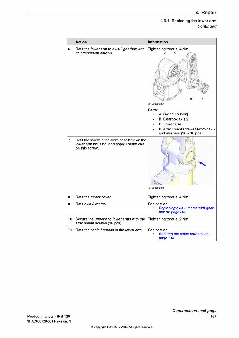
InformationAction
Tightening torque: 4 Nm.AA BB
CC DD
xx1700000767
Refit the lower arm to axis-2 gearbox withits attachment screws.
6
Parts:• A: Swing housing• B: Gearbox axis 2• C: Lower arm• D: Attachment screws M4x25 q12.9
and washers (16 + 16 pcs)
xx1700000768
Refit the screw in the air release hole on thelower arm housing, and apply Loctite 243on this screw.
7
Tightening torque: 4 Nm.Refit the motor cover.8
See section• Replacing axis-3 motor with gear-
box on page 202
Refit axis-3 motor.9
Tightening torque: 2 Nm.Secure the upper and lower arms with theattachment screws (16 pcs).
10
See section• Refitting the cable harness on
page 134
Refit the cable harness in the lower arm.11
Continues on next pageProduct manual - IRB 120 1673HAC035728-001 Revision: N
© Copyright 2009-2017 ABB. All rights reserved.
4 Repair4.6.1 Replacing the lower arm
Continued
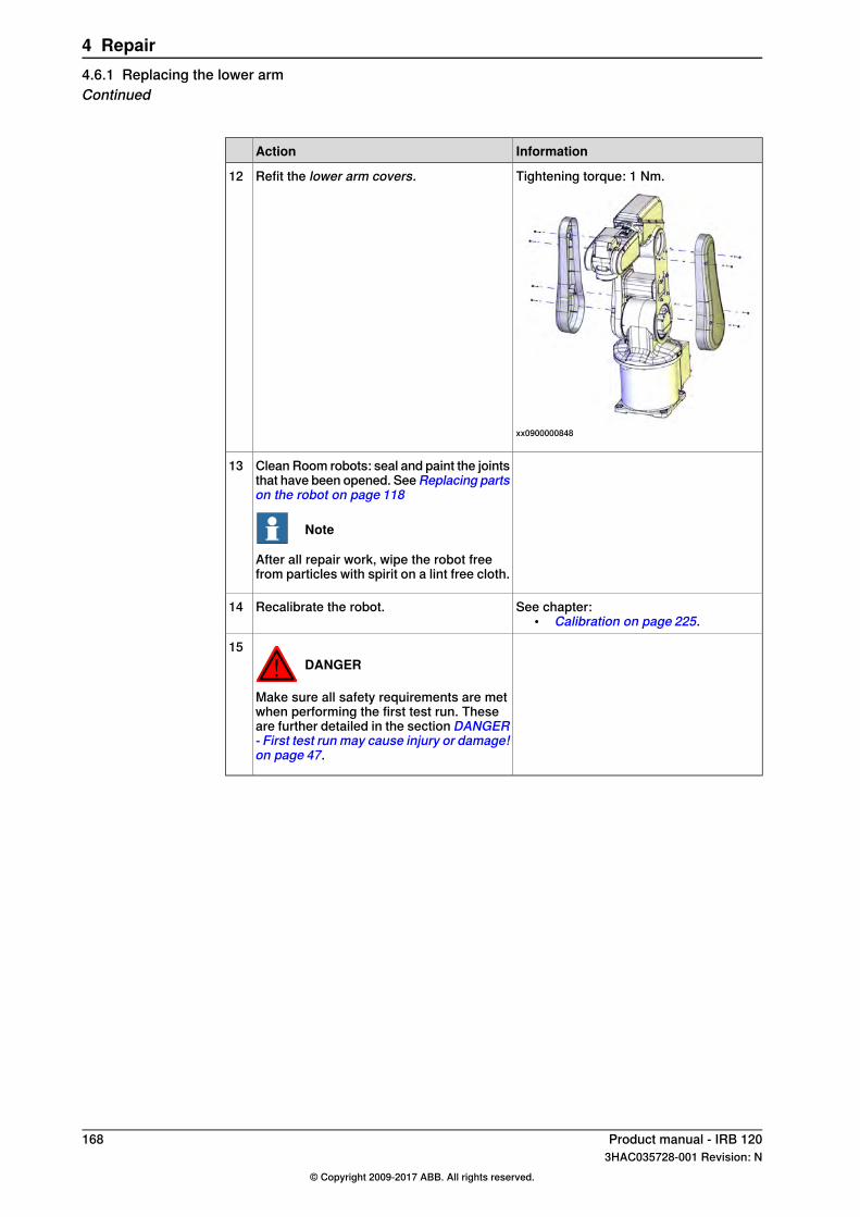
InformationAction
Tightening torque: 1 Nm.
xx0900000848
Refit the lower arm covers.12
Clean Room robots: seal and paint the jointsthat have been opened. SeeReplacing partson the robot on page 118
Note
After all repair work, wipe the robot freefrom particles with spirit on a lint free cloth.
13
See chapter:• Calibration on page 225.
Recalibrate the robot.14
DANGER
Make sure all safety requirements are metwhen performing the first test run. Theseare further detailed in the section DANGER- First test run may cause injury or damage!on page 47.
15
168 Product manual - IRB 1203HAC035728-001 Revision: N
© Copyright 2009-2017 ABB. All rights reserved.
4 Repair4.6.1 Replacing the lower armContinued
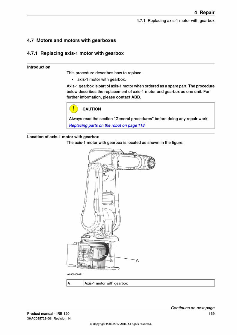
4.7 Motors and motors with gearboxes
4.7.1 Replacing axis-1 motor with gearbox
IntroductionThis procedure describes how to replace:
• axis-1 motor with gearbox.Axis-1 gearbox is part of axis-1 motor when ordered as a spare part. The procedurebelow describes the replacement of axis-1 motor and gearbox as one unit. Forfurther information, please contact ABB.
CAUTION
Always read the section "General procedures" before doing any repair work.Replacing parts on the robot on page 118
Location of axis-1 motor with gearboxThe axis-1 motor with gearbox is located as shown in the figure.
A
xx0900000871
Axis-1 motor with gearboxA
Continues on next pageProduct manual - IRB 120 1693HAC035728-001 Revision: N
© Copyright 2009-2017 ABB. All rights reserved.
4 Repair4.7.1 Replacing axis-1 motor with gearbox

There are two different designs of the swing plate, inside the base. One of thedesigns has an air release hole and the other does not.
xx1500000112
Required equipment
NoteEquipment
The content is defined in the sectionStandard toolkit on page 260.
Standard toolkit
These procedures include references tothe tools required.
Other tools and procedures may be required.See references to these procedures in the step-by-step instructions below.
Amount 2 mlFlange sealant, for example Loctite 574
Shell Alvania Grease WR2Cable grease
Mobil FM222. Used for lubrication of cablecontact areas for robots with food gradelubrication.
Cable grease, for food grade lubrication
Loctite 243
Continues on next page170 Product manual - IRB 120
3HAC035728-001 Revision: N© Copyright 2009-2017 ABB. All rights reserved.
4 Repair4.7.1 Replacing axis-1 motor with gearboxContinued

Removing the axis-1 motor with gearboxUse these procedures to remove the axis-1 motor, with gearbox.
Removal, step 1 - Preparations
InformationAction
Note
If the robot is fitted in any other positionthan floor mounted, it must first be removedfrom this position. The replacing procedureof the axis-1 motor with gearbox is bestperformed with the robot in an upright posi-tion.
1
CAUTION
Use caution performing these procedures.The cable harness will still be fitted or partlyfitted during the procedures.
2
The two most back screws that secure theswing house, are difficult to reach with axis-1 in calibration position. Therefore jog axis-1 to be able to reach those screws.
3
Jog axis 1 to 90° position.4
xx1300001598
Remove the two attachment screws secur-ing the swing housing to the base. (Notpossible to reach with axis 1 in 0° position.)
5
xx1300001599
Continues on next pageProduct manual - IRB 120 1713HAC035728-001 Revision: N
© Copyright 2009-2017 ABB. All rights reserved.
4 Repair4.7.1 Replacing axis-1 motor with gearbox
Continued
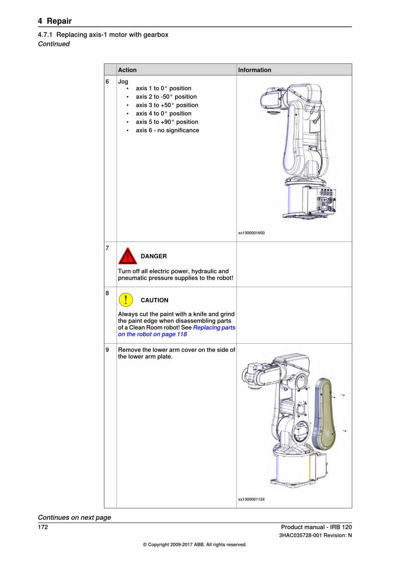
InformationAction
xx1300001600
Jog• axis 1 to 0° position• axis 2 to -50° position• axis 3 to +50° position• axis 4 to 0° position• axis 5 to +90° position• axis 6 - no significance
6
DANGER
Turn off all electric power, hydraulic andpneumatic pressure supplies to the robot!
7
CAUTION
Always cut the paint with a knife and grindthe paint edge when disassembling partsof a Clean Room robot! SeeReplacing partson the robot on page 118
8
xx1300001124
Remove the lower arm cover on the side ofthe lower arm plate.
9
Continues on next page172 Product manual - IRB 120
3HAC035728-001 Revision: N© Copyright 2009-2017 ABB. All rights reserved.
4 Repair4.7.1 Replacing axis-1 motor with gearboxContinued

Removal, step 2 - Swing housing
InformationAction
CAUTION
Always cut the paint with a knife and grindthe paint edge when disassembling partsof a Clean Room robot! SeeReplacing partson the robot on page 118
1
A B
xx0900000879
BracketA
Attachment screws (2 pcs)B
Remove the cable bracket from the lowerarm.
2
Cut cable ties at motor axis 2.3
Disconnect connectors:• R2.MP2• R2.ME2
4
xx1300001604
Remove the remaining attachment screwssecuring the swing housing.
5
If needed, use two screws to press theswing housing out.
6
Continues on next pageProduct manual - IRB 120 1733HAC035728-001 Revision: N
© Copyright 2009-2017 ABB. All rights reserved.
4 Repair4.7.1 Replacing axis-1 motor with gearbox
Continued

InformationAction
xx0900000857
Attachment screws (2 pcs)A
Cable guides (2 pcs)B
Remove both cable guides.7
Carefully pull the axis 2 motor cables outas long as possible.
8
Guide the cable harness and carefullypush/pull it in below motor in axis2, as longas possible, without damaging any cables.
Note
Do not use excessive force!
9
Tip
Use a solid box in a suitable size made ofa material that will not damage the robotin any way. Some plastic in the bottom ofthe box makes a good "bed" for the robotto rest on.
Carefully lift the upper arm, lower arm, andswing housing and put it down close to thebase of the robot as far as the (still connec-ted) cable harness permit.
CAUTION
Do not stretch the cable harness.
10
Continues on next page174 Product manual - IRB 120
3HAC035728-001 Revision: N© Copyright 2009-2017 ABB. All rights reserved.
4 Repair4.7.1 Replacing axis-1 motor with gearboxContinued
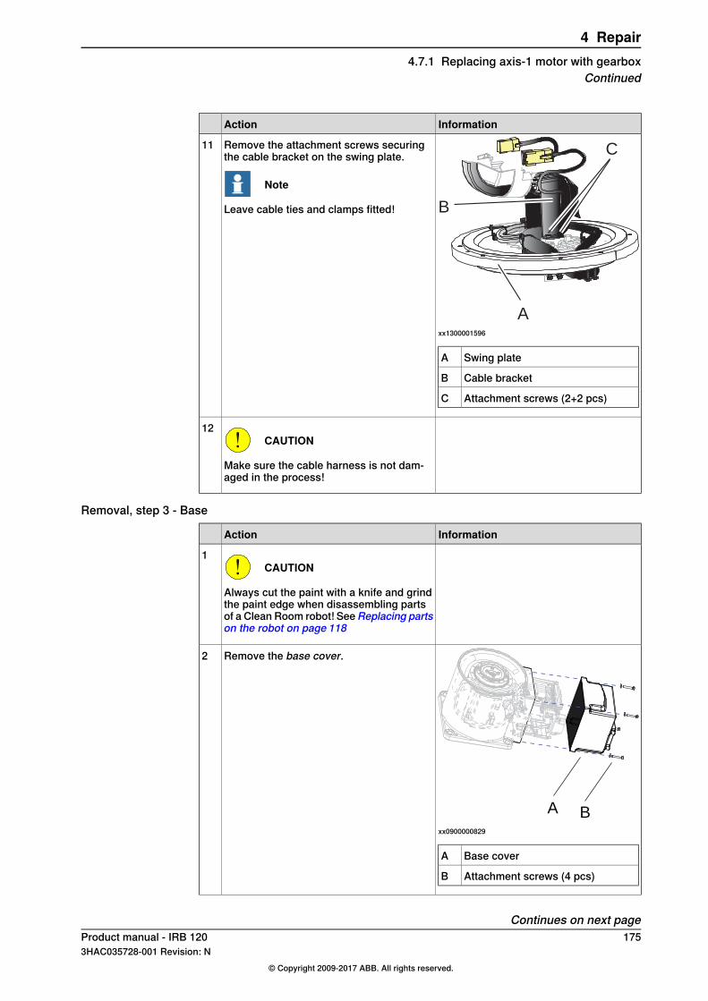
InformationAction
A
B
C
xx1300001596
Swing plateA
Cable bracketB
Attachment screws (2+2 pcs)C
Remove the attachment screws securingthe cable bracket on the swing plate.
Note
Leave cable ties and clamps fitted!
11
CAUTION
Make sure the cable harness is not dam-aged in the process!
12
Removal, step 3 - Base
InformationAction
CAUTION
Always cut the paint with a knife and grindthe paint edge when disassembling partsof a Clean Room robot! SeeReplacing partson the robot on page 118
1
A B
xx0900000829
Base coverA
Attachment screws (4 pcs)B
Remove the base cover.2
Continues on next pageProduct manual - IRB 120 1753HAC035728-001 Revision: N
© Copyright 2009-2017 ABB. All rights reserved.
4 Repair4.7.1 Replacing axis-1 motor with gearbox
Continued

InformationAction
xx0900000831
PlateA
Attachment screws (4 pcs)B
Remove the plate with the EIB board andbattery fitted, and pull it out in order to reachthe connector of the battery cable.
3
CAUTION
Disconnect the battery cable connector verycarefully! If too much force is used there isa risk of damaging the connector!
4
xx1500000002
Loosen attachment screws holding cablebracket with connectors.
5
Cut the cable ties connecting the axis-1motor cables to the base.
6
Disconnect the axis-1 motor cables.7
Removal, step 4 - Axis-1 motor with gearbox
InformationAction
CAUTION
Always cut the paint with a knife and grindthe paint edge when disassembling partsof a Clean Room robot! SeeReplacing partson the robot on page 118
1
Continues on next page176 Product manual - IRB 120
3HAC035728-001 Revision: N© Copyright 2009-2017 ABB. All rights reserved.
4 Repair4.7.1 Replacing axis-1 motor with gearboxContinued

InformationAction
xx1300001605
Attachment screws and washers (16+ 16 pcs)
A
Swing plateB
BaseC
Remove the attachment screws securingthe swing plate.
2
xx1400002558
Tip
Make a note of the position of the swingplate before removing it.
3
xx1300001606
Use caution and lift the swing plate up andput it close to the rest of the removed armsystem of the robot. Use the protrude holesto force the swing plate loose.
CAUTION
Do not damage the cable harness!
4
CAUTION
Protect the gearbox from dust and/or foreignparticles.
5
Remove screw from swing plate centre.6
Continues on next pageProduct manual - IRB 120 1773HAC035728-001 Revision: N
© Copyright 2009-2017 ABB. All rights reserved.
4 Repair4.7.1 Replacing axis-1 motor with gearbox
Continued
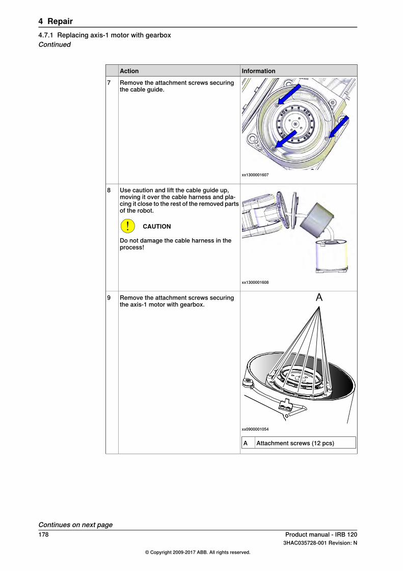
InformationAction
xx1300001607
Remove the attachment screws securingthe cable guide.
7
xx1300001608
Use caution and lift the cable guide up,moving it over the cable harness and pla-cing it close to the rest of the removed partsof the robot.
CAUTION
Do not damage the cable harness in theprocess!
8
xx0900001054
Attachment screws (12 pcs)A
Remove the attachment screws securingthe axis-1 motor with gearbox.
9
Continues on next page178 Product manual - IRB 120
3HAC035728-001 Revision: N© Copyright 2009-2017 ABB. All rights reserved.
4 Repair4.7.1 Replacing axis-1 motor with gearboxContinued
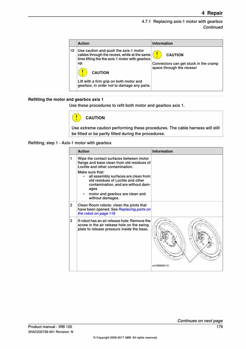
InformationAction
CAUTION
Connectors can get stuck in the crampspace through the recess!
Use caution and push the axis-1 motorcables through the recess, while at the sametime lifting the the axis-1 motor with gearboxup.
CAUTION
Lift with a firm grip on both motor andgearbox, in order not to damage any parts.
10
Refitting the motor and gearbox axis 1Use these procedures to refit both motor and gearbox axis 1.
CAUTION
Use extreme caution performing these procedures. The cable harness will stillbe fitted or be partly fitted during the procedures.
Refitting, step 1 - Axis-1 motor with gearbox
InformationAction
Wipe the contact surfaces between motorflange and base clean from old residues ofLoctite and other contamination.
1
Make sure that:• all assembly surfaces are clean from
old residues of Loctite and othercontamination, and are without dam-ages
• motor and gearbox are clean andwithout damages.
Clean Room robots: clean the joints thathave been opened. See Replacing parts onthe robot on page 118
2
xx1500000112
If robot has an air release hole: Remove thescrew in the air release hole on the swingplate to release pressure inside the base.
3
Continues on next pageProduct manual - IRB 120 1793HAC035728-001 Revision: N
© Copyright 2009-2017 ABB. All rights reserved.
4 Repair4.7.1 Replacing axis-1 motor with gearbox
Continued
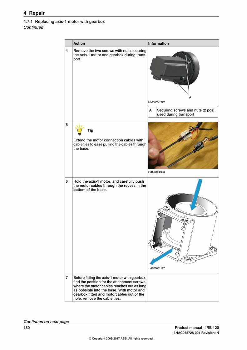
InformationAction
xx0900001050
Securing screws and nuts (2 pcs),used during transport
A
Remove the two screws with nuts securingthe axis-1 motor and gearbox during trans-port.
4
xx1500000003
Tip
Extend the motor connection cables withcable ties to ease pulling the cables throughthe base.
5
xx1300001117
Hold the axis-1 motor, and carefully pushthe motor cables through the recess in thebottom of the base.
6
Before fitting the axis-1 motor with gearbox,find the position for the attachment screws,where the motor cables reaches out as longas possible into the base. With motor andgearbox fitted and motorcables out of thehole, remove the cable ties.
7
Continues on next page180 Product manual - IRB 120
3HAC035728-001 Revision: N© Copyright 2009-2017 ABB. All rights reserved.
4 Repair4.7.1 Replacing axis-1 motor with gearboxContinued

InformationAction
Tightening torque: 4 Nm
xx0900001054
Attachment screw, M4x40 q12.9 (12pcs)
A
Secure the axis-1 motor with gearbox.8
xx0900000800
Attachment screws M3x8 q12.9 (3pcs)
A
Cable guideB
BaseC
Use caution and move the cable guide overthe cable harness and fit it in the base.
CAUTION
Make sure not to damage the cable pack-age.
xx1300001608
9
Tightening torque: 2 Nm.Secure the cable guide with its attachmentscrews.
10
Apply cable grease on the inside surfacesof the cable guide.
11
Continues on next pageProduct manual - IRB 120 1813HAC035728-001 Revision: N
© Copyright 2009-2017 ABB. All rights reserved.
4 Repair4.7.1 Replacing axis-1 motor with gearbox
Continued

Refitting, step 2 - Base
InformationAction
Clean Room robots: clean the joints thathave been opened. See Replacing parts onthe robot on page 118
1
Wipe clean the contact surfaces betweenbase and swing plate from old residues ofLoctite and other contamination.
2
Wipe clean countersink hole in swing plateand screw.
3
AA
xx0900000835
Area where to apply Loctite 574A
Apply flange sealant (Loctite 574) on theassembly surfaces on swing plate and gear.
4
xx1300001125
Apply a thin layer of cable grease on theplastic surface of the part of the cable guidefitted on the swing plate.
5
Apply cable grease on cables and hosesbefore running the package in through thecable guide.
6
Continues on next page182 Product manual - IRB 120
3HAC035728-001 Revision: N© Copyright 2009-2017 ABB. All rights reserved.
4 Repair4.7.1 Replacing axis-1 motor with gearboxContinued
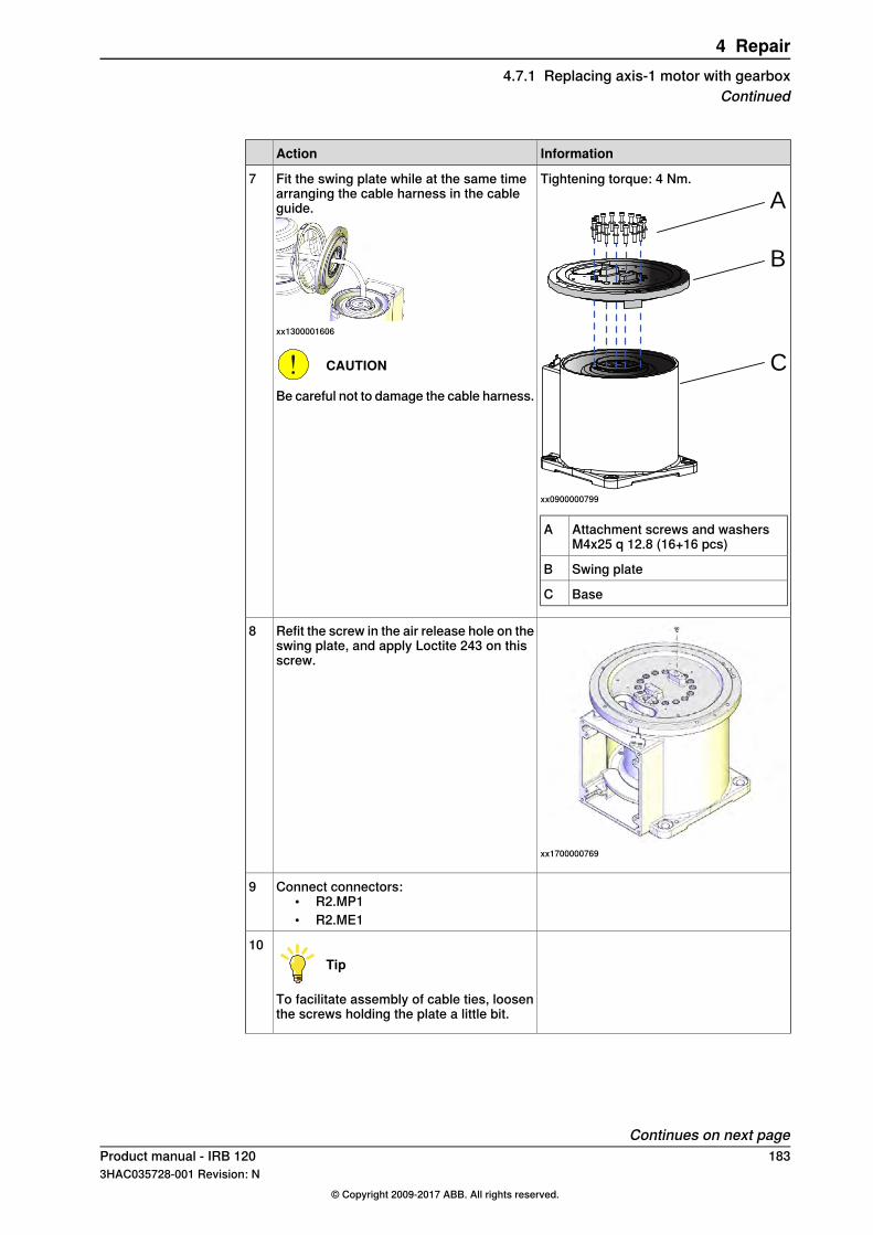
InformationAction
Tightening torque: 4 Nm.
A
B
C
xx0900000799
Attachment screws and washersM4x25 q 12.8 (16+16 pcs)
A
Swing plateB
BaseC
Fit the swing plate while at the same timearranging the cable harness in the cableguide.
xx1300001606
CAUTION
Be careful not to damage the cable harness.
7
xx1700000769
Refit the screw in the air release hole on theswing plate, and apply Loctite 243 on thisscrew.
8
Connect connectors:• R2.MP1• R2.ME1
9
Tip
To facilitate assembly of cable ties, loosenthe screws holding the plate a little bit.
10
Continues on next pageProduct manual - IRB 120 1833HAC035728-001 Revision: N
© Copyright 2009-2017 ABB. All rights reserved.
4 Repair4.7.1 Replacing axis-1 motor with gearbox
Continued

InformationAction
xx1400002559
Secure the connectors to the plate withcable ties.
11
Refit the attachment screws that secure thecable plate, if removed.
12
Use caution and reconnect the battery cableconnector.
CAUTION
If too much force is used when the batterycable is connected, there is a risk of dam-aging the connector.
13
Tip
Leaving the attachment screws securingthe bracket with battery unscrewed, willmake it easier to connect the battery cable.
Secure the bracket with battery (if it hasbeen removed).
14
Make sure the earth cable is connected andundamaged.
15
xx0900000836
Use caution and push in the plate with theEIB board and battery into the base.
Note
Make sure that the cables are placed cor-rectly and that no cables are damaged!
16
Parts:• A: Plate• B: Attachment screws M3x8 q12.8
(4 pcs)
Tightening torque: 2 Nm.Secure the plate with its attachment screws.17
Continues on next page184 Product manual - IRB 120
3HAC035728-001 Revision: N© Copyright 2009-2017 ABB. All rights reserved.
4 Repair4.7.1 Replacing axis-1 motor with gearboxContinued

InformationAction
Tightening torque: 4 Nm.
A B
xx0900000829
Use caution and refit the base cover.
CAUTION
Make sure not to damage the cables in theprocess.
18
Parts:• A: Base cover• B: Attachment screws M4x25 q12.8
(4 pcs)
Refitting, step 3 - Swing house
InformationAction
Clean Room robots: clean the joints thathave been opened. See Replacing parts onthe robot on page 118
1
Lift swing house and armsystem (upper andlower arms) and hold the parts in an anglein order to be able to fit the cable holder onthe swing plate.
Tip
The easiest and most safe way to do this,is with two persons working together:
• Person 1 holding the armsystem inan angle
• Person 2 fitting the cable holder.
2
Continues on next pageProduct manual - IRB 120 1853HAC035728-001 Revision: N
© Copyright 2009-2017 ABB. All rights reserved.
4 Repair4.7.1 Replacing axis-1 motor with gearbox
Continued
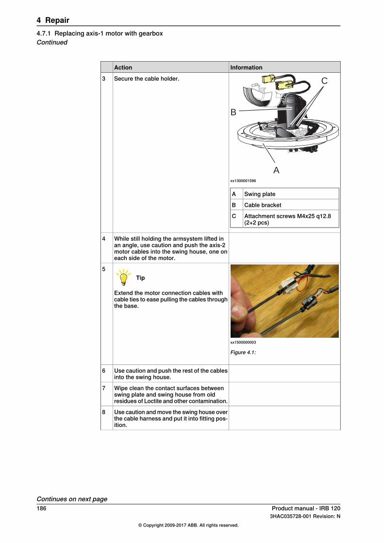
InformationAction
A
B
C
xx1300001596
Swing plateA
Cable bracketB
Attachment screws M4x25 q12.8(2+2 pcs)
C
Secure the cable holder.3
While still holding the armsystem lifted inan angle, use caution and push the axis-2motor cables into the swing house, one oneach side of the motor.
4
xx1500000003
Figure 4.1:
Tip
Extend the motor connection cables withcable ties to ease pulling the cables throughthe base.
5
Use caution and push the rest of the cablesinto the swing house.
6
Wipe clean the contact surfaces betweenswing plate and swing house from oldresidues of Loctite and other contamination.
7
Use caution and move the swing house overthe cable harness and put it into fitting pos-ition.
8
Continues on next page186 Product manual - IRB 120
3HAC035728-001 Revision: N© Copyright 2009-2017 ABB. All rights reserved.
4 Repair4.7.1 Replacing axis-1 motor with gearboxContinued

InformationAction
Tightening torque: 4 Nm.
xx1300001604
M4x25 (6 pcs)
Secure the swing house with the six attach-ment screws possible to reach at this point.
9
Attachment screws M4x25 q12.9 (6 pcs)
Refitting, step 4 - Concluding procedure
InformationAction
Clean Room robots: seal and paint the jointsthat have been opened. SeeReplacing partson the robot on page 118
Note
After all repair work, wipe the robot freefrom particles with spirit on a lint free cloth.
1
Connect connectors:• R2.MP2• R2.ME2
2
Arrange the axis-2 motor cables so that theywill not be damaged.
3
Secure the motor cables around the axis-2motor with a cable tie.
4
Continues on next pageProduct manual - IRB 120 1873HAC035728-001 Revision: N
© Copyright 2009-2017 ABB. All rights reserved.
4 Repair4.7.1 Replacing axis-1 motor with gearbox
Continued
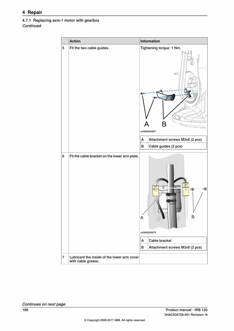
InformationAction
Tightening torque: 1 Nm.
xx0900000857
Attachment screws M3x8 (2 pcs)A
Cable guides (2 pcs)B
Fit the two cable guides.5
A B
xx0900000879
Cable bracketA
Attachment screws M3x8 (2 pcs)B
Fit the cable bracket on the lower arm plate.6
Lubricant the inside of the lower arm coverwith cable grease.
7
Continues on next page188 Product manual - IRB 120
3HAC035728-001 Revision: N© Copyright 2009-2017 ABB. All rights reserved.
4 Repair4.7.1 Replacing axis-1 motor with gearboxContinued
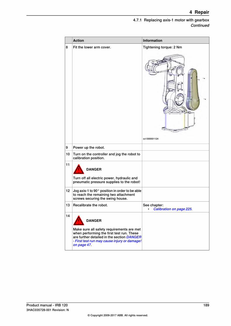
InformationAction
Tightening torque: 2 Nm
xx1300001124
Fit the lower arm cover.8
Power up the robot.9
Turn on the controller and jog the robot tocalibration position.
10
DANGER
Turn off all electric power, hydraulic andpneumatic pressure supplies to the robot!
11
Jog axis-1 to 90° position in order to be ableto reach the remaining two attachmentscrews securing the swing house.
12
See chapter:• Calibration on page 225.
Recalibrate the robot.13
DANGER
Make sure all safety requirements are metwhen performing the first test run. Theseare further detailed in the section DANGER- First test run may cause injury or damage!on page 47.
14
Product manual - IRB 120 1893HAC035728-001 Revision: N
© Copyright 2009-2017 ABB. All rights reserved.
4 Repair4.7.1 Replacing axis-1 motor with gearbox
Continued

4.7.2 Replacing axis-2 motor with gearbox
IntroductionThis procedure describes how to replace:
• motor axis 2 with gearbox.Gearbox axis 2 is a part of motor axis 2 when ordered as a spare part. Theprocedure below describes the replacement of motor and gearbox axis 2 as oneunit. For information how to replace gearbox axis 2, please contact ABB.
CAUTION
Always read the section "General procedures" before doing any repair work.Replacing parts on the robot on page 118
Location of motor axis-2 with gearboxAxis-2 motor with gearbox is located as shown in the figure.
AB
C
xx0900000847
Cable harnessA
Motor axis-3B
Motor axis-2 with gearboxC
Continues on next page190 Product manual - IRB 120
3HAC035728-001 Revision: N© Copyright 2009-2017 ABB. All rights reserved.
4 Repair4.7.2 Replacing axis-2 motor with gearbox
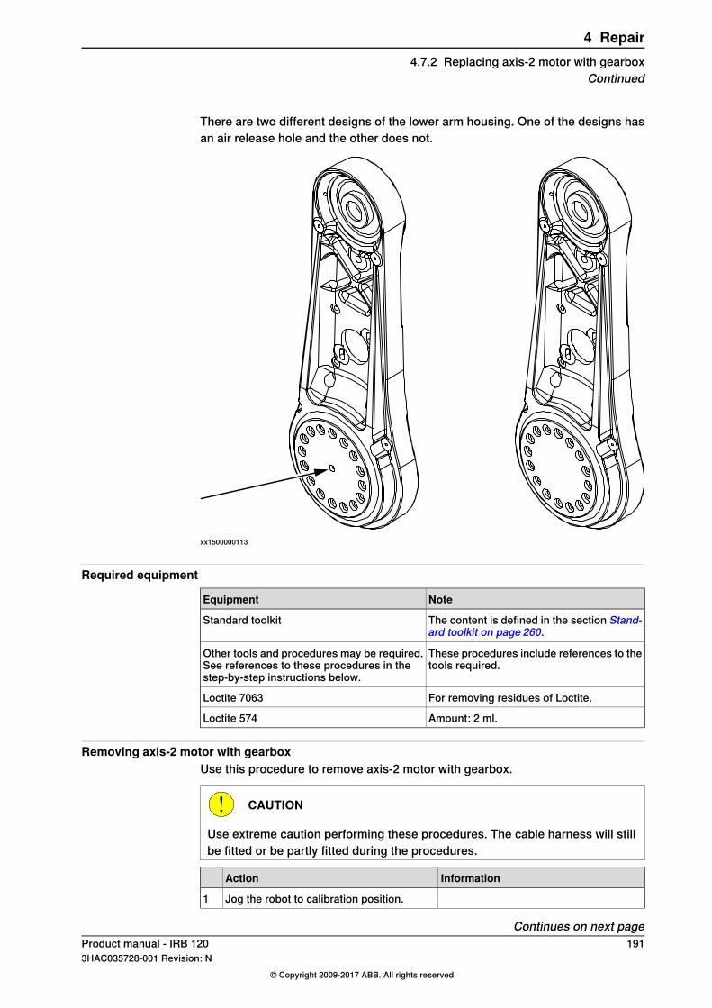
There are two different designs of the lower arm housing. One of the designs hasan air release hole and the other does not.
xx1500000113
Required equipment
NoteEquipment
The content is defined in the section Stand-ard toolkit on page 260.
Standard toolkit
These procedures include references to thetools required.
Other tools and procedures may be required.See references to these procedures in thestep-by-step instructions below.
For removing residues of Loctite.Loctite 7063
Amount: 2 ml.Loctite 574
Removing axis-2 motor with gearboxUse this procedure to remove axis-2 motor with gearbox.
CAUTION
Use extreme caution performing these procedures. The cable harness will stillbe fitted or be partly fitted during the procedures.
InformationAction
Jog the robot to calibration position.1
Continues on next pageProduct manual - IRB 120 1913HAC035728-001 Revision: N
© Copyright 2009-2017 ABB. All rights reserved.
4 Repair4.7.2 Replacing axis-2 motor with gearbox
Continued
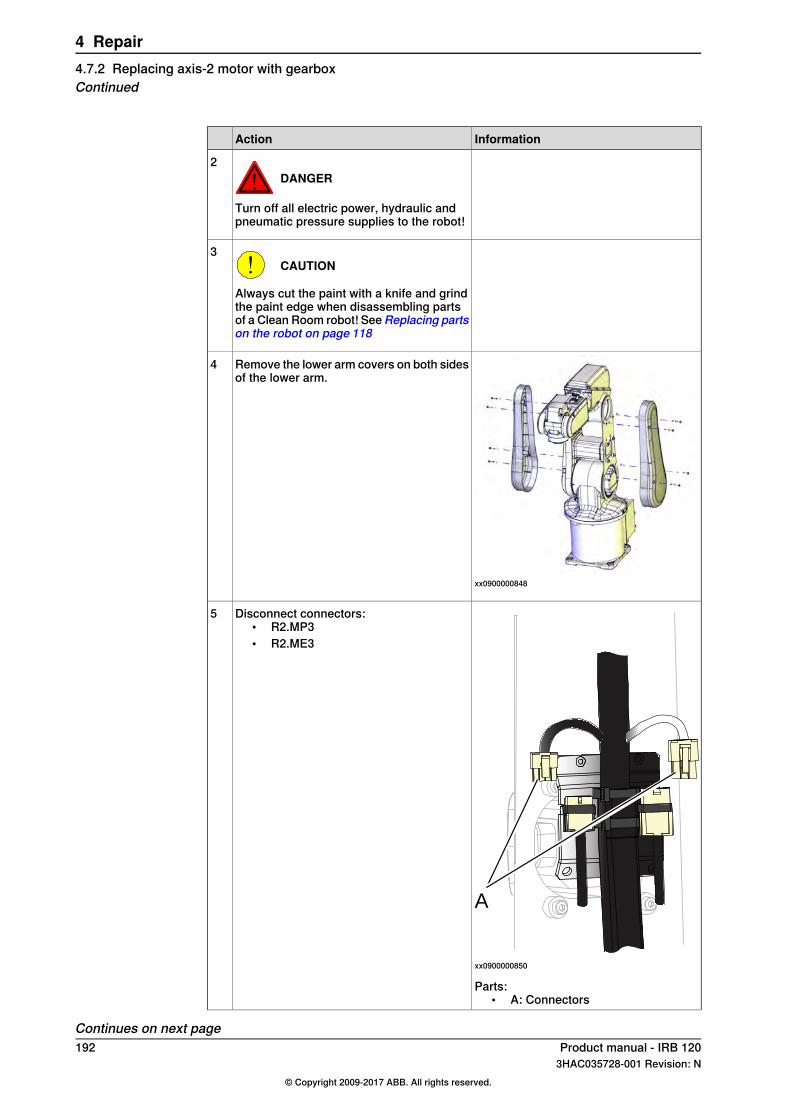
InformationAction
DANGER
Turn off all electric power, hydraulic andpneumatic pressure supplies to the robot!
2
CAUTION
Always cut the paint with a knife and grindthe paint edge when disassembling partsof a Clean Room robot! SeeReplacing partson the robot on page 118
3
xx0900000848
Remove the lower arm covers on both sidesof the lower arm.
4
A
xx0900000850
Disconnect connectors:• R2.MP3• R2.ME3
5
Parts:• A: Connectors
Continues on next page192 Product manual - IRB 120
3HAC035728-001 Revision: N© Copyright 2009-2017 ABB. All rights reserved.
4 Repair4.7.2 Replacing axis-2 motor with gearboxContinued
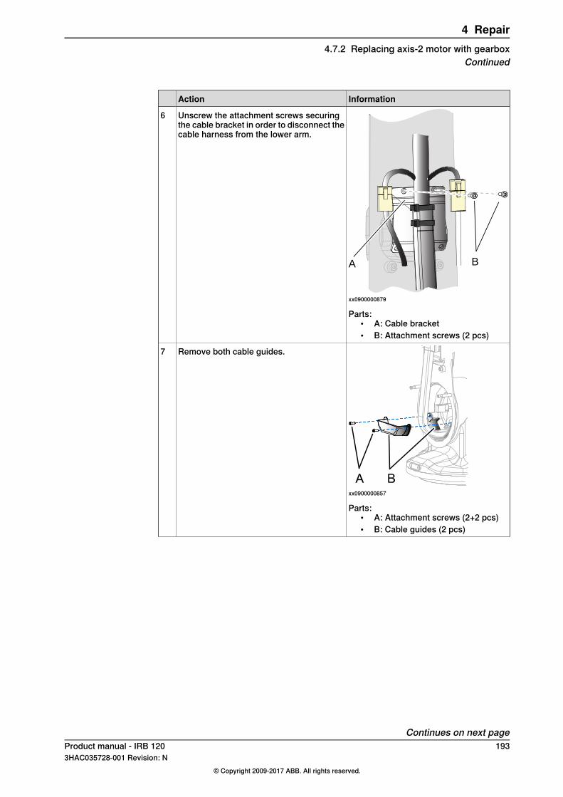
InformationAction
A B
xx0900000879
Unscrew the attachment screws securingthe cable bracket in order to disconnect thecable harness from the lower arm.
6
Parts:• A: Cable bracket• B: Attachment screws (2 pcs)
xx0900000857
Remove both cable guides.7
Parts:• A: Attachment screws (2+2 pcs)• B: Cable guides (2 pcs)
Continues on next pageProduct manual - IRB 120 1933HAC035728-001 Revision: N
© Copyright 2009-2017 ABB. All rights reserved.
4 Repair4.7.2 Replacing axis-2 motor with gearbox
Continued
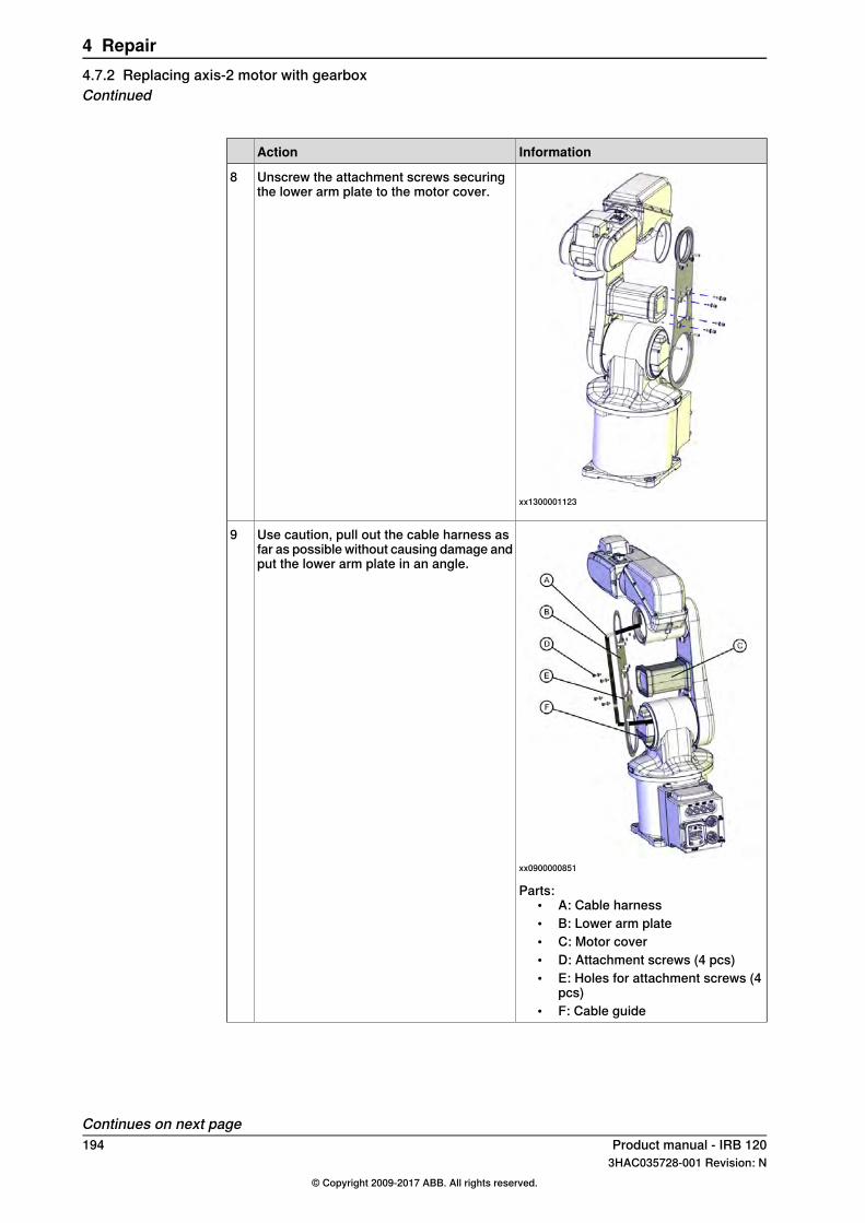
InformationAction
xx1300001123
Unscrew the attachment screws securingthe lower arm plate to the motor cover.
8
xx0900000851
Use caution, pull out the cable harness asfar as possible without causing damage andput the lower arm plate in an angle.
9
Parts:• A: Cable harness• B: Lower arm plate• C: Motor cover• D: Attachment screws (4 pcs)• E: Holes for attachment screws (4
pcs)• F: Cable guide
Continues on next page194 Product manual - IRB 120
3HAC035728-001 Revision: N© Copyright 2009-2017 ABB. All rights reserved.
4 Repair4.7.2 Replacing axis-2 motor with gearboxContinued

InformationAction
xx1300001121
Leave two attachment screws fitted andunscrew the remaining screws, that securethe lower arm to the axis-2 gearbox.
10
Take a hold of the upper and lower arm ina firm grip.
11
xx1300001119
Use caution and unscrew the two remainingattachment screws that secure the lowerarm to the axis-2 gearbox.
12
Air hole design:13Remove screw from swing plate.
Use caution and put the lower and upperarms beside the swing housing and base,making sure not to damage the cable har-ness.
Tip
Place the armsystem on some plastic or ina box with soft edges. The armsystem mustbe placed in a way that it will not be able tomove or be moved.
14
Disconnect connectors:• R2.MP2• R2.ME2
15
Continues on next pageProduct manual - IRB 120 1953HAC035728-001 Revision: N
© Copyright 2009-2017 ABB. All rights reserved.
4 Repair4.7.2 Replacing axis-2 motor with gearbox
Continued

InformationAction
xx1300001120
Unscrew the attachment screws and plainwashers that secure the axis-2 motor withgearbox to the swing housing, use cautionand remove the axis-2 motor.
CAUTION
In order not to damage any parts, hold thetwo parts in a firm grip when removing themotor with gearbox.
16
Refitting motor axis 2 with gearboxUse this procedure to refit motor axis 2 with gearbox.
CAUTION
Use extreme caution performing these procedures. The cable harness will stillbe fitted or be partly fitted during the procedures.
InformationAction
Clean Room robots: clean the joints thathave been opened. See Replacing parts onthe robot on page 118
1
Tip
Use Loctite 7063 (Superclean).
Before refitting, make sure that:• all assembly surfaces are clean and
without damages• motor and gearbox are clean and
without damages.
2
xx0900001050
Remove the two screws with nuts securingmotor axis 2 with gearbox while beingtransported.
3
Parts:• A: Screws with nuts, used during
transport (2 pcs)
Remove old residues of Loctite and othercontamination, from the assembly surfacesof the lower arm.
4
Wipe clean screw and countersink hole onswing plate.
5
Continues on next page196 Product manual - IRB 120
3HAC035728-001 Revision: N© Copyright 2009-2017 ABB. All rights reserved.
4 Repair4.7.2 Replacing axis-2 motor with gearboxContinued

InformationAction
Refill the same amount of grease in thegearbox, that has been wiped off.
6
xx1500000113
If the robot has an air release hole: Removethe screw in the air release hole on thelower arm housing to release pressure in-side the lower arm.
7
Apply flange sealant (Loctite 574) on theassembly surfaces of the lower arm andgearbox.
8
xx1300001120
Place the axis-2 motor with gearbox in theswing housing.
CAUTION
In order not to damage any parts, hold thetwo parts in a firm grip when refitting themotor with gearbox.
9
Tightening torque: 4 Nm.
xx1300001122
Secure the axis-2 motor with gearbox to theswing housing with its attachment screws.
10
Attachment screws M4x20 q12.9 (12 pcs)
Continues on next pageProduct manual - IRB 120 1973HAC035728-001 Revision: N
© Copyright 2009-2017 ABB. All rights reserved.
4 Repair4.7.2 Replacing axis-2 motor with gearbox
Continued

InformationAction
xx1300001119
While holding the upper and lower arms,secure the lower arm to the axis-2 motorwith gearbox with two of the attachmentscrews.
11
Tightening torque: 4 Nm.
xx1300001121
Secure the axis-2 motor with gearbox to thelower arm with the remaining attachmentscrews. Tighten all screws.
12
Attachment screws M4x25 q12.9 andwashers (16 + 16 pcs)
xx1500000113
If the robot has an air release hole: AddLoctite 243 and refit the screw in the air re-lease hole on the lower arm housing.
13
Continues on next page198 Product manual - IRB 120
3HAC035728-001 Revision: N© Copyright 2009-2017 ABB. All rights reserved.
4 Repair4.7.2 Replacing axis-2 motor with gearboxContinued
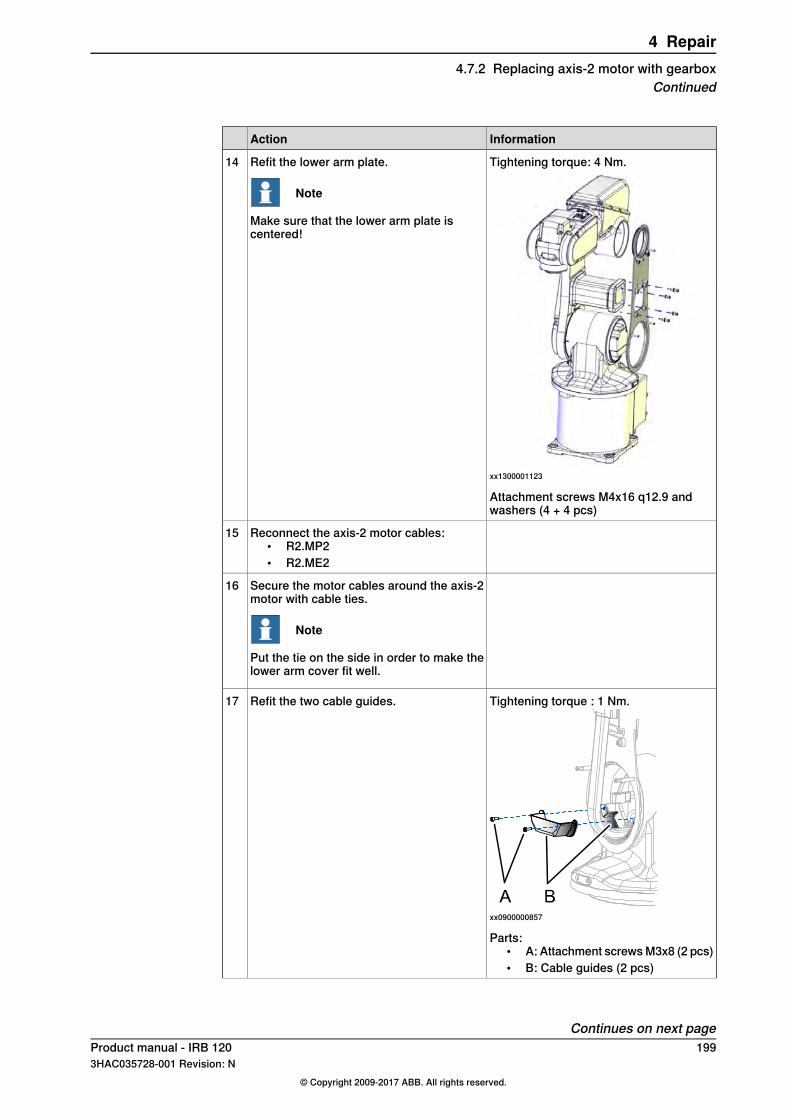
InformationAction
Tightening torque: 4 Nm.
xx1300001123
Refit the lower arm plate.
Note
Make sure that the lower arm plate iscentered!
14
Attachment screws M4x16 q12.9 andwashers (4 + 4 pcs)
Reconnect the axis-2 motor cables:• R2.MP2• R2.ME2
15
Secure the motor cables around the axis-2motor with cable ties.
Note
Put the tie on the side in order to make thelower arm cover fit well.
16
Tightening torque : 1 Nm.
xx0900000857
Refit the two cable guides.17
Parts:• A: Attachment screws M3x8 (2 pcs)• B: Cable guides (2 pcs)
Continues on next pageProduct manual - IRB 120 1993HAC035728-001 Revision: N
© Copyright 2009-2017 ABB. All rights reserved.
4 Repair4.7.2 Replacing axis-2 motor with gearbox
Continued

InformationAction
A
xx0900000850
Reconnect connectors:• R2.MP3• R2.ME3.
18
Connectors:• A: R2.ME3• B: R2.MP3
A B
xx0900000879
Refit the cable bracket on the lower arm.19
Parts:• A: Cable bracket• B: Attachment screws M3x8 (2 pcs)
DANGER
Check that the cable harness is intact andconnected correctly on all axes!
20
Continues on next page200 Product manual - IRB 120
3HAC035728-001 Revision: N© Copyright 2009-2017 ABB. All rights reserved.
4 Repair4.7.2 Replacing axis-2 motor with gearboxContinued

InformationAction
Tightening torque: 2 Nm.
xx0900000848
Refit the lower arm covers.21
Clean Room robots: seal and paint the jointsthat have been opened. SeeReplacing partson the robot on page 118
Note
After all repair work, wipe the robot freefrom particles with spirit on a lint free cloth.
22
See chapter:• Calibration on page 225.
Recalibrate the robot.23
DANGER
Make sure all safety requirements are metwhen performing the first test run. Theseare further detailed in the section DANGER- First test run may cause injury or damage!on page 47.
24
Product manual - IRB 120 2013HAC035728-001 Revision: N
© Copyright 2009-2017 ABB. All rights reserved.
4 Repair4.7.2 Replacing axis-2 motor with gearbox
Continued
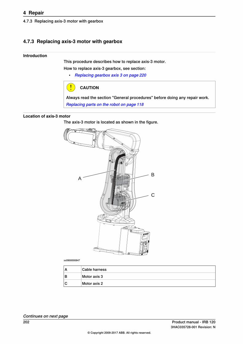
4.7.3 Replacing axis-3 motor with gearbox
IntroductionThis procedure describes how to replace axis-3 motor.How to replace axis-3 gearbox, see section:
• Replacing gearbox axis 3 on page 220
CAUTION
Always read the section "General procedures" before doing any repair work.Replacing parts on the robot on page 118
Location of axis-3 motorThe axis-3 motor is located as shown in the figure.
AB
C
xx0900000847
Cable harnessA
Motor axis 3B
Motor axis 2C
Continues on next page202 Product manual - IRB 120
3HAC035728-001 Revision: N© Copyright 2009-2017 ABB. All rights reserved.
4 Repair4.7.3 Replacing axis-3 motor with gearbox

Required equipment
NoteEquipment
The content is defined in the section Standardtoolkit on page 260.
Standard toolkit
These procedures include references to thetools required.
Other tools and procedures may be re-quired. See references to these proceduresin the step-by-step instructions below.
Amount: 2 ml.Flange sealant (Loctite 574)
Removing axis-3 motorUse this procedure to replace axis-3 motor.
InformationAction
Secure the arm system before removingmotor axis 3.
1
DANGER
Turn off all electric power, hydraulic andpneumatic pressure supplies to the robot!
2
CAUTION
Always cut the paint with a knife and grindthe paint edge when disassembling partsof a Clean Room robot! SeeReplacing partson the robot on page 118
3
xx0900000848
Remove the lower arm covers on both sidesof the of the lower arm.
4
Continues on next pageProduct manual - IRB 120 2033HAC035728-001 Revision: N
© Copyright 2009-2017 ABB. All rights reserved.
4 Repair4.7.3 Replacing axis-3 motor with gearbox
Continued

InformationAction
xx0900000849
Cut the cable straps securing the connect-ors.
5
Parts:• A: Cable straps (2 pcs)
A
xx0900000850
Disconnect connectors:• R2.MP3• R2.ME3.
6
Parts:• A: Connectors R2.MP3 and R2.ME3
Continues on next page204 Product manual - IRB 120
3HAC035728-001 Revision: N© Copyright 2009-2017 ABB. All rights reserved.
4 Repair4.7.3 Replacing axis-3 motor with gearboxContinued

InformationAction
A B
xx0900000879
Unscrew the attachment screws securingthe cable bracket.
7
Parts:• A: Cable bracket• B: Attachment screws (2 pcs)
Move the cable harness a little to the side.8
Unscrew the attachment screws securingthe motor axis 3.
9
xx0900000876
Remove the timing belt from the pulleys onthe motor axis.
10
Parts:• A: Timing belt• B: Pulleys (2 pcs)
Remove the motor.11
Refitting axis-3 motorUse this procedure to refit axis-3 motor.
InformationAction
Clean Room robots: clean the joints thathave been opened. See Replacing parts onthe robot on page 118
1
Continues on next pageProduct manual - IRB 120 2053HAC035728-001 Revision: N
© Copyright 2009-2017 ABB. All rights reserved.
4 Repair4.7.3 Replacing axis-3 motor with gearbox
Continued

InformationAction
Make sure that:• all assembly surfaces are clean and
without damages• motor and gearbox are clean and
undamaged.
2
Place the axis-3 motor in the motor cover.3
xx0900000876
Refit the timing belt on the pulleys.4
Parts:• A: Timing belt• B: Pulleys (2 pcs)
Tighten the attachment screws andwasherssecuring the motor, just enough to still beable to move the motor.
5
New belt: F = 18-19.7NMove the motor to a position where a goodtiming belt tension is reached.
Tip
Use a handheld spring balance to measurethe timing belt tension.
xx1400002560
6Used belt: F = 12.5-14.3N
Note
Do not strech the timing belt too much!
Tightening torque: 4 Nm.Secure the axis-3 motor with its attachmentscrews and washers.
7
Continues on next page206 Product manual - IRB 120
3HAC035728-001 Revision: N© Copyright 2009-2017 ABB. All rights reserved.
4 Repair4.7.3 Replacing axis-3 motor with gearboxContinued

InformationAction
Tightening torque: 4 Nm.
xx0900000851
Refit the lower arm plate.8
Parts:• A: Cable harness• B: Lower arm plate• C: Motor cover• D: Attachment screws (4 pcs)• E: Holes for attachment screws (4
pcs)• F: Cable guide
Reconnect connectors:• R2.MP3• R2.ME3.
9
Continues on next pageProduct manual - IRB 120 2073HAC035728-001 Revision: N
© Copyright 2009-2017 ABB. All rights reserved.
4 Repair4.7.3 Replacing axis-3 motor with gearbox
Continued

InformationAction
Tightening torque: 1 Nm.
A B
xx0900000879
Secure the cable harness by refitting thecable bracket to the lower arm plate.
10
Parts:• A: Cable bracket• B: Attachment screws (2 pcs)
xx0900000849
Secure the connectors with cable ties.
Note
Put the strap tie on the side in order to makethe lower arm cover fit well.
11
Parts:• A: Cable ties (2 pcs)
Continues on next page208 Product manual - IRB 120
3HAC035728-001 Revision: N© Copyright 2009-2017 ABB. All rights reserved.
4 Repair4.7.3 Replacing axis-3 motor with gearboxContinued
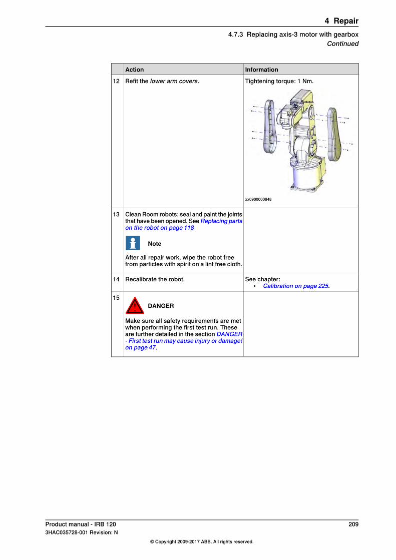
InformationAction
Tightening torque: 1 Nm.
xx0900000848
Refit the lower arm covers.12
Clean Room robots: seal and paint the jointsthat have been opened. SeeReplacing partson the robot on page 118
Note
After all repair work, wipe the robot freefrom particles with spirit on a lint free cloth.
13
See chapter:• Calibration on page 225.
Recalibrate the robot.14
DANGER
Make sure all safety requirements are metwhen performing the first test run. Theseare further detailed in the section DANGER- First test run may cause injury or damage!on page 47.
15
Product manual - IRB 120 2093HAC035728-001 Revision: N
© Copyright 2009-2017 ABB. All rights reserved.
4 Repair4.7.3 Replacing axis-3 motor with gearbox
Continued
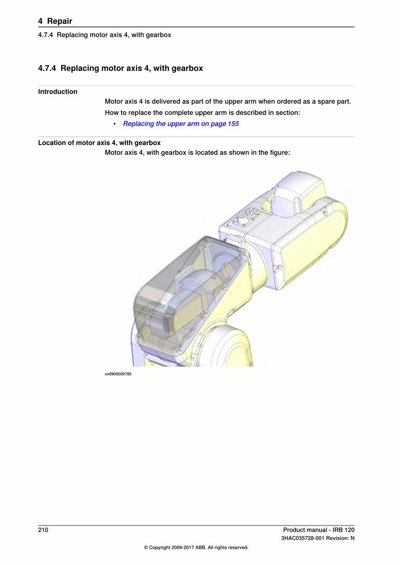
4.7.4 Replacing motor axis 4, with gearbox
IntroductionMotor axis 4 is delivered as part of the upper arm when ordered as a spare part.How to replace the complete upper arm is described in section:
• Replacing the upper arm on page 155
Location of motor axis 4, with gearboxMotor axis 4, with gearbox is located as shown in the figure:
xx0900000785
210 Product manual - IRB 1203HAC035728-001 Revision: N
© Copyright 2009-2017 ABB. All rights reserved.
4 Repair4.7.4 Replacing motor axis 4, with gearbox
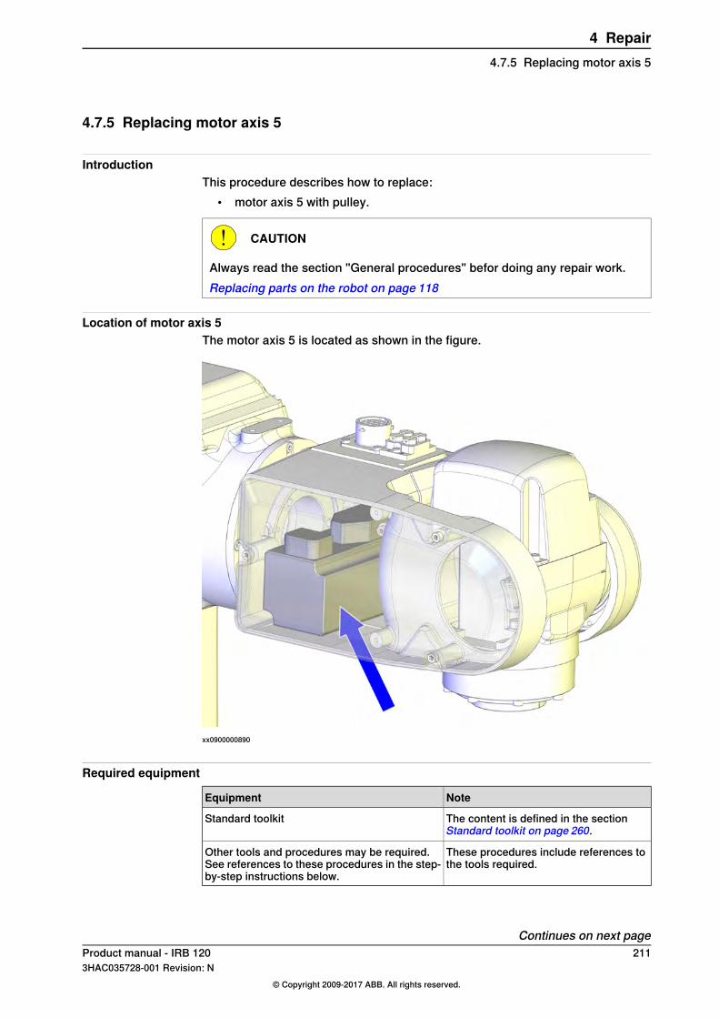
4.7.5 Replacing motor axis 5
IntroductionThis procedure describes how to replace:
• motor axis 5 with pulley.
CAUTION
Always read the section "General procedures" befor doing any repair work.Replacing parts on the robot on page 118
Location of motor axis 5The motor axis 5 is located as shown in the figure.
xx0900000890
Required equipment
NoteEquipment
The content is defined in the sectionStandard toolkit on page 260.
Standard toolkit
These procedures include references tothe tools required.
Other tools and procedures may be required.See references to these procedures in the step-by-step instructions below.
Continues on next pageProduct manual - IRB 120 2113HAC035728-001 Revision: N
© Copyright 2009-2017 ABB. All rights reserved.
4 Repair4.7.5 Replacing motor axis 5

Removing motor axis 5 with pulleyUse this procedure to remove motor axis 5 with pulley.
InformationAction
DANGER
Turn off all electric power, hydraulic andpneumatic pressure supplies to the robot!
1
CAUTION
Always cut the paint with a knife and grindthe paint edge when disassembling partsof a Clean Room robot! SeeReplacing partson the robot on page 118
2
xx0900000886
Remove thewrist side covers on both sidesof the wrist.
3
Parts:• A: Wrist side covers (2 pcs)
xx0900000887
Loosen the attachment screw securing theclamp.
4
Parts:• A: Attachment screw• B: Clamp
Continues on next page212 Product manual - IRB 120
3HAC035728-001 Revision: N© Copyright 2009-2017 ABB. All rights reserved.
4 Repair4.7.5 Replacing motor axis 5Continued

InformationAction
xx0900000888
Remove the connector support.5
Parts:• A: Attachment screws (2 pcs)• B: Connector support
xx0900001009
Cut the cable straps.6
Parts:• A: Cable straps (2 pcs)
Disconnect connectors for motor axis 5:• R2.MP5• R2.ME5
7
xx1100000960
Unscrew the attachment screws securingmotor axis 5.
8
Continues on next pageProduct manual - IRB 120 2133HAC035728-001 Revision: N
© Copyright 2009-2017 ABB. All rights reserved.
4 Repair4.7.5 Replacing motor axis 5
Continued
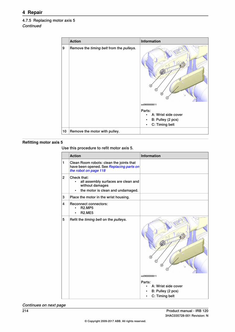
InformationAction
xx0900000611
Remove the timing belt from the pulleys.9
Parts:• A: Wrist side cover• B: Pulley (2 pcs)• C: Timing belt
Remove the motor with pulley.10
Refitting motor axis 5Use this procedure to refit motor axis 5.
InformationAction
Clean Room robots: clean the joints thathave been opened. See Replacing parts onthe robot on page 118
1
Check that:• all assembly surfaces are clean and
without damages• the motor is clean and undamaged.
2
Place the motor in the wrist housing.3
Reconnect connectors:• R2.MP5• R2.ME5
4
xx0900000611
Refit the timing belt on the pulleys.5
Parts:• A: Wrist side cover• B: Pulley (2 pcs)• C: Timing belt
Continues on next page214 Product manual - IRB 120
3HAC035728-001 Revision: N© Copyright 2009-2017 ABB. All rights reserved.
4 Repair4.7.5 Replacing motor axis 5Continued

InformationAction
xx1100000960
Tighten the attachment screws andwasherssecuring the motor, just enough (2 Nm) tostill be able to move the motor.
6
Attachment screws M5x16 q12.9 andwashers (2 + 2 pcs)
New belt: F = 7.6-8.4NMove the motor to a position where a goodtiming belt tension is reached.
7Used belt: F = 5.3-6.1N
Tightening torque: 4 Nm.Secure motor axis 5 with its attachmentscrews and washers.
8
Tightening torque: 1 Nm.
xx0900000888
Refit the connector support.9
Parts:• A: Attachment screws (2 pcs)• B: Connector support
Tightening torque: 1 Nm.
xx0900000887
Refit the clamp with its attachment screw.10
Parts:• A: Attachment screw• B: Clamp
Continues on next pageProduct manual - IRB 120 2153HAC035728-001 Revision: N
© Copyright 2009-2017 ABB. All rights reserved.
4 Repair4.7.5 Replacing motor axis 5
Continued

InformationAction
xx0900001009
Secure the cables with cable straps.11
Parts:• A: Cable straps (2 pcs)
Tightening torque: 1 Nm.
xx0900000886
Refit the wrist side covers.12
Parts:• A: Wrist side covers (2 pcs)
Clean Room robots: seal and paint the jointsthat have been opened. SeeReplacing partson the robot on page 118
Note
After all repair work, wipe the robot freefrom particles with spirit on a lint free cloth.
13
See chapter:• Calibration on page 225.
Recalibrate the robot.14
DANGER
Make sure all safety requirements are metwhen performing the first test run. Theseare further detailed in the section DANGER- First test run may cause injury or damage!on page 47.
15
216 Product manual - IRB 1203HAC035728-001 Revision: N
© Copyright 2009-2017 ABB. All rights reserved.
4 Repair4.7.5 Replacing motor axis 5Continued
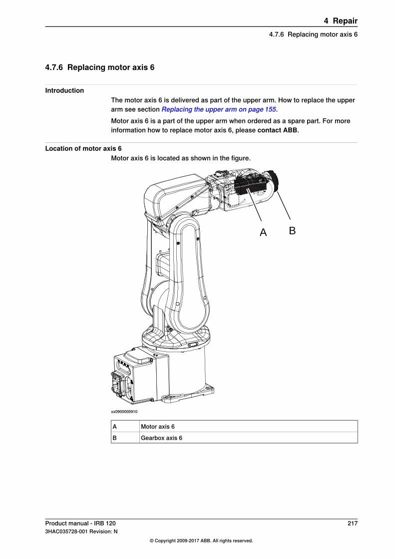
4.7.6 Replacing motor axis 6
IntroductionThe motor axis 6 is delivered as part of the upper arm. How to replace the upperarm see section Replacing the upper arm on page 155.Motor axis 6 is a part of the upper arm when ordered as a spare part. For moreinformation how to replace motor axis 6, please contact ABB.
Location of motor axis 6Motor axis 6 is located as shown in the figure.
A B
xx0900000910
Motor axis 6A
Gearbox axis 6B
Product manual - IRB 120 2173HAC035728-001 Revision: N
© Copyright 2009-2017 ABB. All rights reserved.
4 Repair4.7.6 Replacing motor axis 6

4.8 Gearboxes
4.8.1 Replacing gearbox axis 1
IntroductionThe gearbox axis 1 is delivered as a part of motor axis 1. For information how toreplace motor with gearbox axis 1, see sectionReplacing axis-1 motor with gearboxon page 169.
218 Product manual - IRB 1203HAC035728-001 Revision: N
© Copyright 2009-2017 ABB. All rights reserved.
4 Repair4.8.1 Replacing gearbox axis 1
4.8.2 Replacing gearbox axis 2
IntroductionThe gearbox axis 2 is delivered as a part of motor axis 2. For information how toreplace motor with gearbox axis 2, see sectionReplacing axis-2 motor with gearboxon page 190.
Product manual - IRB 120 2193HAC035728-001 Revision: N
© Copyright 2009-2017 ABB. All rights reserved.
4 Repair4.8.2 Replacing gearbox axis 2
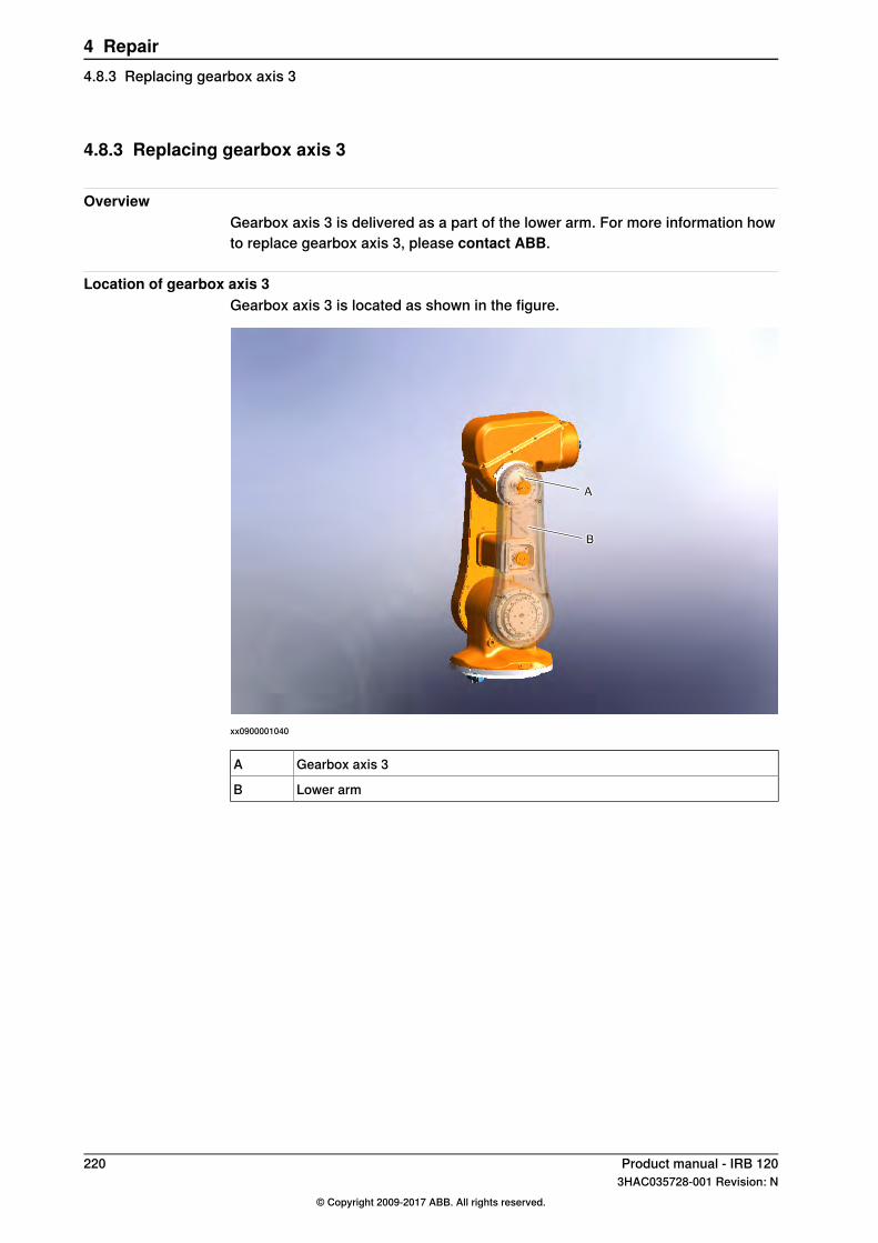
4.8.3 Replacing gearbox axis 3
OverviewGearbox axis 3 is delivered as a part of the lower arm. For more information howto replace gearbox axis 3, please contact ABB.
Location of gearbox axis 3Gearbox axis 3 is located as shown in the figure.
xx0900001040
Gearbox axis 3A
Lower armB
220 Product manual - IRB 1203HAC035728-001 Revision: N
© Copyright 2009-2017 ABB. All rights reserved.
4 Repair4.8.3 Replacing gearbox axis 3

4.8.4 Replacing gearbox axis 4
IntroductionGearbox axis 4 is delivered as a part of the upper arm.How to replace the upper arm see:
• Replacing the upper arm on page 155For more information how to replace gearbox axis 4, please contact ABB.
Product manual - IRB 120 2213HAC035728-001 Revision: N
© Copyright 2009-2017 ABB. All rights reserved.
4 Repair4.8.4 Replacing gearbox axis 4
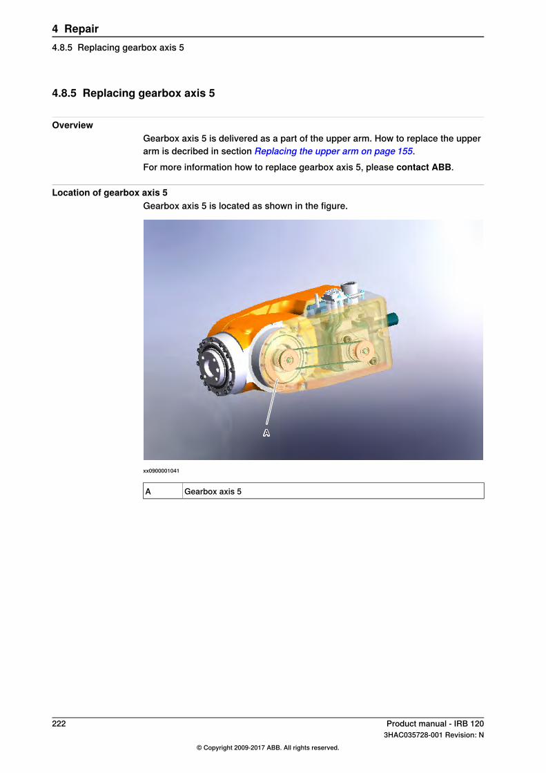
4.8.5 Replacing gearbox axis 5
OverviewGearbox axis 5 is delivered as a part of the upper arm. How to replace the upperarm is decribed in section Replacing the upper arm on page 155.For more information how to replace gearbox axis 5, please contact ABB.
Location of gearbox axis 5Gearbox axis 5 is located as shown in the figure.
xx0900001041
Gearbox axis 5A
222 Product manual - IRB 1203HAC035728-001 Revision: N
© Copyright 2009-2017 ABB. All rights reserved.
4 Repair4.8.5 Replacing gearbox axis 5

4.8.6 Replacing gearbox axis 6
IntroductionThe gearbox axis 6 is delivered as part of the upper arm. How to replace the upperarm is described in section Replacing the upper arm on page 155.For more information how to replace gearbox axis 6, please contact ABB.
Location of gearbox axis 6Gearbox axis 6 is located as shown in the figure:
A B
xx0900000910
Motor axis 6A
Gearbox axis 6B
Product manual - IRB 120 2233HAC035728-001 Revision: N
© Copyright 2009-2017 ABB. All rights reserved.
4 Repair4.8.6 Replacing gearbox axis 6

This page is intentionally left blank

5 Calibration5.1 Introduction to calibration
5.1.1 Introduction and calibration terminology
Calibration informationThis chapter includes general information about the recommended calibrationmethods and also the detailed procedures for updating the revolution counters,checking the calibration position etc.Detailed instructions of how to perform Axis Calibration are given on theFlexPendant during the calibration procedure. To prepare calibration with AxisCalibration method, see Calibrating with Axis Calibration method on page 235.
Calibration terminology
DefinitionTerm
A collective term for several methods that might beavailable for calibrating the ABB robot. Each methodcontains calibration routines.
Calibration method
Known position of the complete robot where theangle of each axis can be checked against visualsynchronization marks.
Synchronization position
Known position of the complete robot that is usedfor calibration of the robot.
Calibration position
A generic term for all calibration methods that aimto move the robot to calibration position.
Standard calibration
A calibration routine that generates a new zero posi-tion of the robot.
Fine calibration
A calibration routine that in the first step generatesa reference to current zero position of the robot. Thesame calibration routine can later on be used to re-calibrate the robot back to the same position as whenthe reference was stored.
Reference calibration
This routine is more flexible compared to fine calib-ration and is used when tools and process equipmentare installed.Requires that a reference is created before beingused for recalibrating the robot.
A calibration routine to make a rough calibration ofeach manipulator axis.
Update revolution counter
Visual marks on the robot axes. When marks arealigned, the robot is in synchronization position.
Synchronization mark
Product manual - IRB 120 2253HAC035728-001 Revision: N
© Copyright 2009-2017 ABB. All rights reserved.
5 Calibration5.1.1 Introduction and calibration terminology

5.1.2 Calibration methods
OverviewThis section specifies the different types of calibration and the calibration methodsthat are supplied by ABB.
Types of calibration
Calibration methodDescriptionType of calibration
Axis Calibration ormanual calibration i
The calibrated robot is positioned at calibrationposition.Standard calibration data is found on the SMB(serial measurement board) or EIB in the robot.
Standard calibration
For robots with RobotWare 5.04 or older, thecalibration data is delivered in a file, calib.cfg,supplied with the robot at delivery. The fileidentifies the correct resolver/motor positioncorresponding to the robot home position.
i The robot is calibrated by either manual calibration or Axis Calibration at factory. Always use thesame calibration method as used at the factory.Information about valid calibration method is found on the calibration label or in the calibrationmenu on the FlexPendant.If no data is found related to standard calibration, manual calibration is used as default.
Brief description of calibration methods
Axis Calibration methodAxis Calibration is a standard calibration method for calibration of IRB 120 and isthe most accurate method for the standard calibration. It is the recommendedmethod in order to achieve proper performance.The following routines are available for the Axis Calibration method:
• Fine calibration• Update revolution counters
The calibration equipment for Axis Calibration is delivered as a toolkit.An introduction to the calibration method is given in this manual, see Calibratingwith Axis Calibration method on page 235.The actual instructions of how to perform the calibration procedure and what todo at each step is given on the FlexPendant. You will be guided through thecalibration procedure, step by step.
Manual calibration methodManual calibration method is a method based on releasing the motor brakes ofthe robot and manually moving the robot into a calibration position. The manualcalibration is using the manual methods for fine calibration and updating revolutioncounters. See Calibrating with manual calibration method on page 242.
ReferencesArticle numbers for the calibration tools are listed in the section Special tools onpage 261.
226 Product manual - IRB 1203HAC035728-001 Revision: N
© Copyright 2009-2017 ABB. All rights reserved.
5 Calibration5.1.2 Calibration methods

5.1.3 When to calibrate
When to calibrateThe system must be calibrated if any of the following situations occur.
The resolver values are changedIf resolver values are changed, the robot must be recalibrated using the calibrationmethods supplied by ABB. Calibrate the robot carefully with standard calibration,according to information in this manual.The resolver values will change when parts affecting the calibration position arereplaced on the robot, for example motors or parts of the transmission.
The revolution counter memory is lostIf the revolution counter memory is lost, the counters must be updated. SeeUpdating revolution counters on page 231. This will occur when:
• The battery is discharged• A resolver error occurs• The signal between a resolver and measurement board is interrupted• A robot axis is moved with the control system disconnected
The revolution counters must also be updated after the robot and controller areconnected at the first installation.
The robot is rebuiltIf the robot is rebuilt, for example, after a crash or when the reach ability of a robotis changed, it needs to be recalibrated for new resolver values.
Product manual - IRB 120 2273HAC035728-001 Revision: N
© Copyright 2009-2017 ABB. All rights reserved.
5 Calibration5.1.3 When to calibrate

5.2 Synchronization marks and axis movement directions
5.2.1 Synchronization marks and synchronization position for axes
IntroductionThis section shows the position of the synchronization marks and thesynchronization position for each axis.
Synchronization marks, IRB 120The illustrations show the synchronization marks on IRB 120.
xx0900000574
Calibration mark axis 1A
Calibration mark axis 2B
Calibration mark axis 3C
Continues on next page228 Product manual - IRB 120
3HAC035728-001 Revision: N© Copyright 2009-2017 ABB. All rights reserved.
5 Calibration5.2.1 Synchronization marks and synchronization position for axes
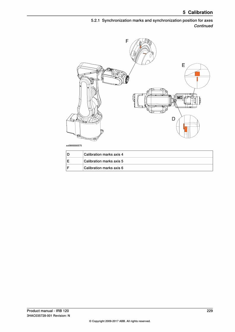
xx0900000575
Calibration marks axis 4D
Calibration marks axis 5E
Calibration marks axis 6F
Product manual - IRB 120 2293HAC035728-001 Revision: N
© Copyright 2009-2017 ABB. All rights reserved.
5 Calibration5.2.1 Synchronization marks and synchronization position for axes
Continued
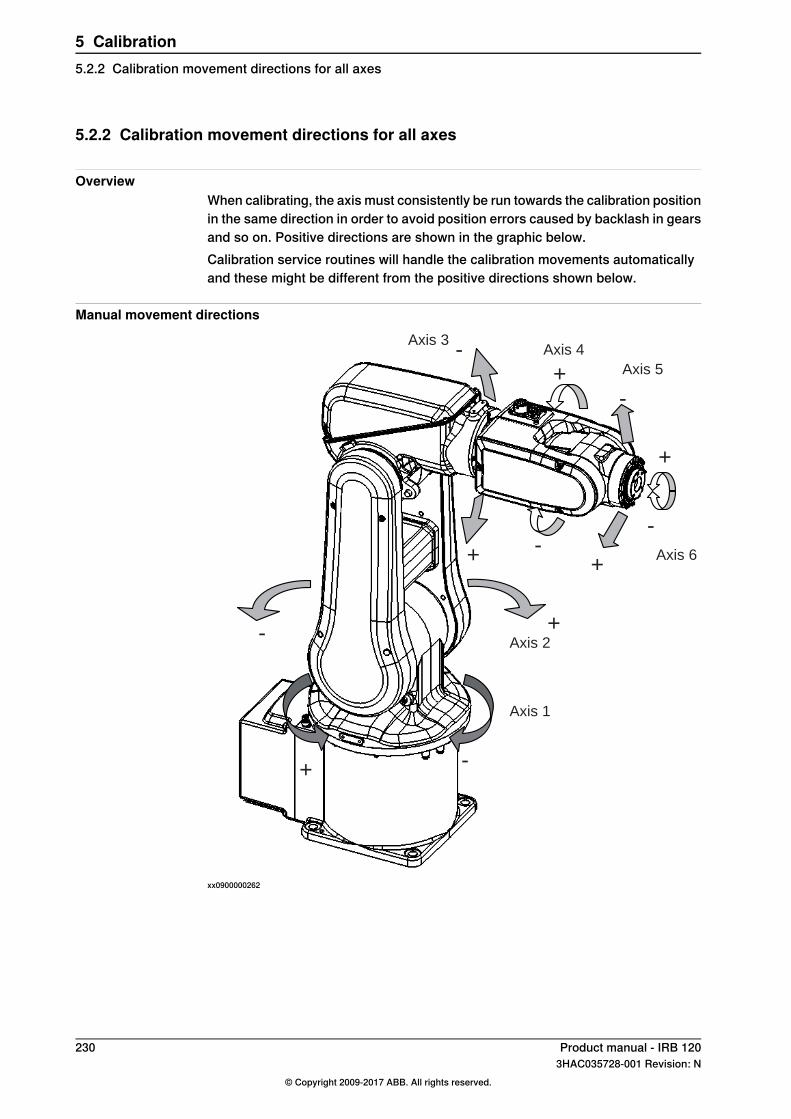
5.2.2 Calibration movement directions for all axes
OverviewWhen calibrating, the axis must consistently be run towards the calibration positionin the same direction in order to avoid position errors caused by backlash in gearsand so on. Positive directions are shown in the graphic below.Calibration service routines will handle the calibration movements automaticallyand these might be different from the positive directions shown below.
Manual movement directions
Axis 1
Axis 2
-Axis 3
Axis 4
+ Axis 5
-
+
--
++
Axis 6
+-
-+
xx0900000262
230 Product manual - IRB 1203HAC035728-001 Revision: N
© Copyright 2009-2017 ABB. All rights reserved.
5 Calibration5.2.2 Calibration movement directions for all axes

5.3 Updating revolution counters
IntroductionThis section describes how to do a rough calibration of each manipulator axis byupdating the revolution counter for each axis, using the FlexPendant.
Step 1 - Manually running the manipulator to the synchronization positionUse this procedure to manually run the manipulator to the synchronization position.
NoteAction
Select axis-by-axis motion mode.1
See Synchronizationmarks and synchron-ization position for axes on page 228.
Jog the manipulator to align the synchron-ization marks.
2
Step 2 - Updating the revolution counterwith the FlexPendant on page 232.
When all axes are positioned, update therevolution counter.
3
Correct calibration position of axis 4 and 6When jogging the manipulator to synchronization position, it is extremely importantto make sure that axes 4 and 6 of the following mentioned manipulators arepositioned correctly. The axes can be calibrated at the wrong turn, resulting in anincorrect manipulator calibration.Make sure the axes are positioned according to the correct calibration values, notonly according to the synchronization marks. The correct values are found on alabel, located either on the lower arm, underneath the flange plate on the base oron the frame.At delivery the manipulator is in the correct position, do NOT rotate axis 4 or 6 atpower up before the revolution counters are updated.If one of the following mentioned axes are rotated one or more turns from itscalibration position before updating the revolution counter, the correct calibrationposition will be lost due to non-integer gear ratio. This affects the followingmanipulators:
Axis 6Axis 4Manipulator variant
YesNoIRB 120
If the synchronization marks seem to be wrong (even if the motor calibration datais correct), try to rotate the axis one turn, update the revolution counter and checkthe synchronization marks again (try both directions, if needed).
Continues on next pageProduct manual - IRB 120 2313HAC035728-001 Revision: N
© Copyright 2009-2017 ABB. All rights reserved.
5 Calibration5.3 Updating revolution counters
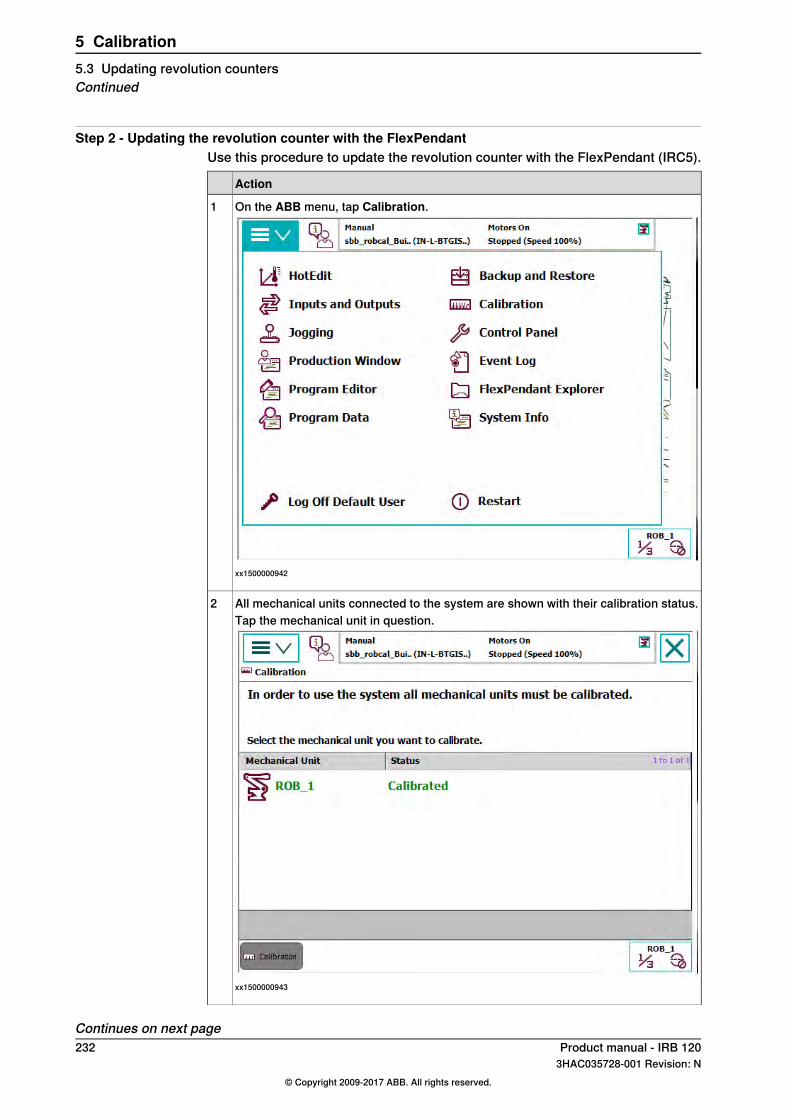
Step 2 - Updating the revolution counter with the FlexPendantUse this procedure to update the revolution counter with the FlexPendant (IRC5).
Action
On the ABB menu, tap Calibration.
xx1500000942
1
All mechanical units connected to the system are shown with their calibration status.2Tap the mechanical unit in question.
xx1500000943
Continues on next page232 Product manual - IRB 120
3HAC035728-001 Revision: N© Copyright 2009-2017 ABB. All rights reserved.
5 Calibration5.3 Updating revolution countersContinued
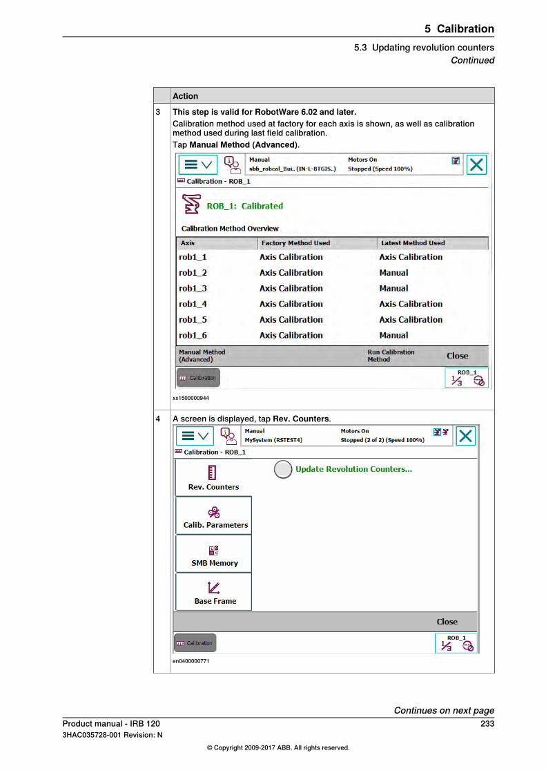
Action
This step is valid for RobotWare 6.02 and later.3Calibration method used at factory for each axis is shown, as well as calibrationmethod used during last field calibration.Tap Manual Method (Advanced).
xx1500000944
A screen is displayed, tap Rev. Counters.
en0400000771
4
Continues on next pageProduct manual - IRB 120 2333HAC035728-001 Revision: N
© Copyright 2009-2017 ABB. All rights reserved.
5 Calibration5.3 Updating revolution counters
Continued

Action
Tap Update Revolution Counters....A dialog box is displayed, warning that updating the revolution counters may changeprogrammed robot positions:
• Tap Yes to update the revolution counters.• Tap No to cancel updating the revolution counters.
Tapping Yes displays the axis selection window.
5
Select the axis to have its revolution counter updated by:• Ticking in the box to the left• Tapping Select all to update all axes.
Then tap Update.
6
A dialog box is displayed, warning that the updating operation cannot be undone:• Tap Update to proceed with updating the revolution counters.• Tap Cancel to cancel updating the revolution counters.
Tapping Update updates the selected revolution counters and removes the tick fromthe list of axes.
7
CAUTION
If a revolution counter is incorrectly updated, it will cause incorrect manipulator posi-tioning, which in turn may cause damage or injury!Check the synchronization position very carefully after each update. See Checkingthe synchronization position on page 249.
8
234 Product manual - IRB 1203HAC035728-001 Revision: N
© Copyright 2009-2017 ABB. All rights reserved.
5 Calibration5.3 Updating revolution countersContinued
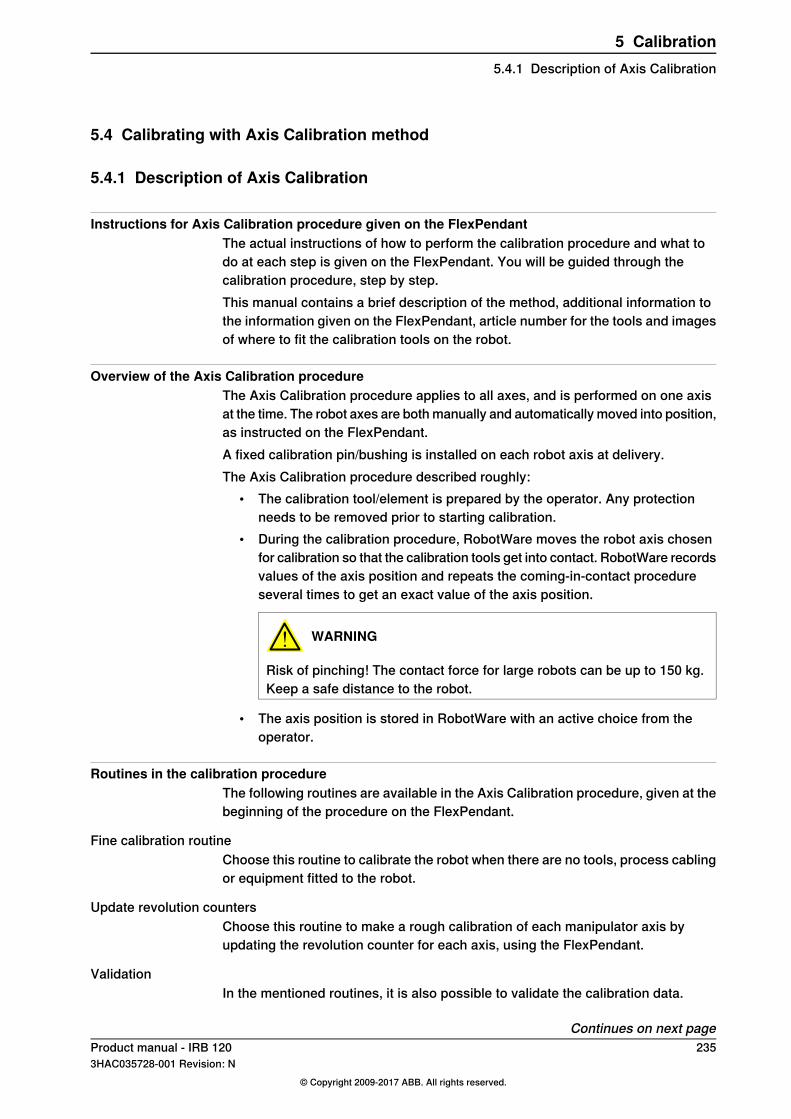
5.4 Calibrating with Axis Calibration method
5.4.1 Description of Axis Calibration
Instructions for Axis Calibration procedure given on the FlexPendantThe actual instructions of how to perform the calibration procedure and what todo at each step is given on the FlexPendant. You will be guided through thecalibration procedure, step by step.This manual contains a brief description of the method, additional information tothe information given on the FlexPendant, article number for the tools and imagesof where to fit the calibration tools on the robot.
Overview of the Axis Calibration procedureThe Axis Calibration procedure applies to all axes, and is performed on one axisat the time. The robot axes are both manually and automatically moved into position,as instructed on the FlexPendant.A fixed calibration pin/bushing is installed on each robot axis at delivery.The Axis Calibration procedure described roughly:
• The calibration tool/element is prepared by the operator. Any protectionneeds to be removed prior to starting calibration.
• During the calibration procedure, RobotWare moves the robot axis chosenfor calibration so that the calibration tools get into contact. RobotWare recordsvalues of the axis position and repeats the coming-in-contact procedureseveral times to get an exact value of the axis position.
WARNING
Risk of pinching! The contact force for large robots can be up to 150 kg.Keep a safe distance to the robot.
• The axis position is stored in RobotWare with an active choice from theoperator.
Routines in the calibration procedureThe following routines are available in the Axis Calibration procedure, given at thebeginning of the procedure on the FlexPendant.
Fine calibration routineChoose this routine to calibrate the robot when there are no tools, process cablingor equipment fitted to the robot.
Update revolution countersChoose this routine to make a rough calibration of each manipulator axis byupdating the revolution counter for each axis, using the FlexPendant.
ValidationIn the mentioned routines, it is also possible to validate the calibration data.
Continues on next pageProduct manual - IRB 120 2353HAC035728-001 Revision: N
© Copyright 2009-2017 ABB. All rights reserved.
5 Calibration5.4.1 Description of Axis Calibration
Position of robot axesThe axis chosen for calibration is automatically run by the calibration program toits calibration position during the calibration procedure.In order for the axis to be able to be moved to calibration position, or in order forgetting proper access to the calibration bushing, other axes might need to bejogged to positions different from 0 degrees. Information about which axes areallowed to be jogged will be given on the FlexPendant. These axes are markedwith Unrestricted in the FlexPendant window.
How to calibrate a suspended or wall mounted robotThe IRB 120 is calibrated floor standing in factory, prior to shipping.To calibrate a suspended or wall mounted robot with the fine calibration routine,the robot must first be taken down and mounted standing on the floor.
236 Product manual - IRB 1203HAC035728-001 Revision: N
© Copyright 2009-2017 ABB. All rights reserved.
5 Calibration5.4.1 Description of Axis CalibrationContinued
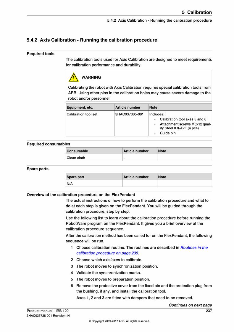
5.4.2 Axis Calibration - Running the calibration procedure
Required toolsThe calibration tools used for Axis Calibration are designed to meet requirementsfor calibration performance and durability.
WARNING
Calibrating the robot with Axis Calibration requires special calibration tools fromABB. Using other pins in the calibration holes may cause severe damage to therobot and/or personnel.
NoteArticle numberEquipment, etc.
Includes:• Calibration tool axes 5 and 6• Attachment screws M5x12 qual-
ity Steel 8.8-A2F (4 pcs)• Guide pin
3HAC037305-001Calibration tool set
Required consumablesNoteArticle numberConsumable
-Clean cloth
Spare parts
NoteArticle numberSpare part
N/A
Overview of the calibration procedure on the FlexPendantThe actual instructions of how to perform the calibration procedure and what todo at each step is given on the FlexPendant. You will be guided through thecalibration procedure, step by step.Use the following list to learn about the calibration procedure before running theRobotWare program on the FlexPendant. It gives you a brief overview of thecalibration procedure sequence.After the calibration method has been called for on the FlexPendant, the followingsequence will be run.
1 Choose calibration routine. The routines are described in Routines in thecalibration procedure on page 235.
2 Choose which axis/axes to calibrate.3 The robot moves to synchronization position.4 Validate the synchronization marks.5 The robot moves to preparation position.6 Remove the protective cover from the fixed pin and the protection plug from
the bushing, if any, and install the calibration tool.Axes 1, 2 and 3 are fitted with dampers that need to be removed.
Continues on next pageProduct manual - IRB 120 2373HAC035728-001 Revision: N
© Copyright 2009-2017 ABB. All rights reserved.
5 Calibration5.4.2 Axis Calibration - Running the calibration procedure

7 The robot performs a measurement sequence by rotating the axis back andforth.
8 Remove the calibration tool and reinstall the protective cover on the fixedpin and the protection plug in the bushing, if any.Refit the dampers on axes 1, 2 and 3.
9 Choose whether to save the calibration data or not.Calibration of the robot is not finished until the calibration data is saved, as laststep of the calibration procedure.
Preparation prior to calibrationThe calibration procedure is described in the FlexPendant while conducting it.
NoteAction
DANGER
While conducting the calibration, the robot needsto be connected to power.Make sure that the robots working area is empty,as the robot can make unpredictable movements.
1
CAUTION
For robots with protection type Clean Room:Always cut the paint with a knife and grind thepaint edge when disassembling parts of the robot!See Replacing parts on the robot on page 118
2
Use a clean cloth.Wipe the calibration tool clean.
Note
The calibration method is exact. Dust, dirt or colorflakes will affect the calibration value.
3
Continues on next page238 Product manual - IRB 120
3HAC035728-001 Revision: N© Copyright 2009-2017 ABB. All rights reserved.
5 Calibration5.4.2 Axis Calibration - Running the calibration procedureContinued

Starting the calibration procedureUse this procedure to call for the Axis Calibration method on the FlexPendant.
NoteAction
On the ABB menu, tap Calibration.
xx1500000942
1
All mechanical units connected to the system areshown with their calibration status.
2
Tap the mechanical unit in question.
xx1500000943
Continues on next pageProduct manual - IRB 120 2393HAC035728-001 Revision: N
© Copyright 2009-2017 ABB. All rights reserved.
5 Calibration5.4.2 Axis Calibration - Running the calibration procedure
Continued

NoteAction
The FlexPendant will give all inform-ation needed to proceed with AxisCalibration.
Calibration method used at factory for each axisis shown, as well as calibration method used forthe robot during last field calibration.
3
Tap Run Calibration Method. The software willautomatically call for the procedure for the validcalibration method.
xx1500000944
A brief overview of the sequencethat will be run on the FlexPendantis given in Overview of the calibra-tion procedure on the FlexPendanton page 237.
Follow the instructions given on the FlexPendant.4
Restarting an interrupted calibration procedureIf the Axis Calibration procedure is interrupted before the calibration is finished,the RobotWare program needs to be started again. Use this procedure to takerequired action.
ActionSituation
Press and hold the three-position enablingdevice and press Play.
The three-position enabling device on theFlexPendant has been released during robotmovement.
Remove the calibration tool, if it is installed,and restart the calibration procedure fromthe beginning. See Starting the calibrationprocedure on page 239.
The RobotWare program is terminated withPP to Main.
If the calibration tool is in contact the robotaxis needs to be jogged in order to releasethe calibration tool. Jogging the axis in wrongdirection will cause the calibration tool tobreak. Directions of axis movement is shownin Calibration movement directions for allaxes on page 230
After calibration
NoteAction
Check that all dampers are refitted on axes 1, 2and 3.
1
Continues on next page240 Product manual - IRB 120
3HAC035728-001 Revision: N© Copyright 2009-2017 ABB. All rights reserved.
5 Calibration5.4.2 Axis Calibration - Running the calibration procedureContinued

NoteAction
B
C
A
xx1000000005
Remove the tool on axis 6.2
Parts:A Attachment screws (4 pcs)B Calibration toolC Guide pin
Product manual - IRB 120 2413HAC035728-001 Revision: N
© Copyright 2009-2017 ABB. All rights reserved.
5 Calibration5.4.2 Axis Calibration - Running the calibration procedure
Continued

5.5 Calibrating with manual calibration method
IntroductionThis section describes how to calibrate the robot manually and how to use thecalibration pins when calibrating.
Note
Calibration can be done in the following ways:• axis 1, 2 and 3 at the same time using the FlexPendant• axis 4, 5 and 6 at the same time using the FlexPendant• each axis separately.
Location of calibration pinsThe figure shows the position of the calibration pins on axes 1 - 6.
A
B
1 2 3
4 5-6
C
D
E
F
xx0900000627
Calibration, axis 1. (Rotate axis 1 -170.2°)1
Calibration pins, axis 1A
Calibration, axis 2. (Rotate axis 2 -115.1°)2
Calibration pins, axis 2B
Calibration, axis 3. (Rotate axis 3 75.8°)3
Calibration pins, axis 3C
Calibration, axis 4. (Rotate axis 4 -174.7°)4
Calibration pins, axis 4D
Calibration, axis 5-6. (Rotate axis 5 -90° and axis 6 90°)5-6
Continues on next page242 Product manual - IRB 120
3HAC035728-001 Revision: N© Copyright 2009-2017 ABB. All rights reserved.
5 Calibration5.5 Calibrating with manual calibration method

Calibration pin, axis 5-6E
Calibration tool, axis 5-6F
Required equipment
NoteEquipment
The content is defined in the section Standardtoolkit on page 260.
Standard toolkit
3HAC037305-001Calibration tool setIncludes:
• Calibration tool axes 5 and 6• Attachment screws M5x12 quality Steel
8.8-A2F (4 pcs)• Guide pin
Calibration using the FlexPendantThis procedure describes how to calibrate the robot using the FlexPendant.
NoteAction
DANGER
Turn off all electric power, hydraulic and pneu-matic pressure supplies to the robot!
1
See the figure in:• Location of calibration pins on
page 242
Remove all dampers from the calibration pins.2
B
C
A
xx1000000005
Fit the calibration tool on axis 6.3
Parts:• A: Attachment screws (4 pcs)• B: Calibration tool• C: Guide pin
How to release the brakes see section:• Manually releasing the brakes
on page 66
Release the brakes.4
See the figure in:• Location of calibration pins on
page 242
Rotate axes 4, 5 and 6 manually until the twocalibration pins of each axis are in contact witheach other.
5
Choose fine calibration from Calib menu.6
Choose Calibrate on the FlexPendant.7
Continues on next pageProduct manual - IRB 120 2433HAC035728-001 Revision: N
© Copyright 2009-2017 ABB. All rights reserved.
5 Calibration5.5 Calibrating with manual calibration method
Continued

NoteAction
Choose axes 4, 5 and 6 on the FlexPendantand Calibrate.
8
After calibration is done, use the FlexPendantto jog each axis to zero degree.
9
See the figure in:• Location of calibration pins on
page 242
Rotate axes 1, 2 and 3 manually until the twocalibration pins of each axis are in contact witheach other.
10
Choose fine calibration from Calib menu.11
Choose axes 1, 2 and 3 on the FlexPendantand Calibrate.
12
See section• Synchronization marks and
synchronization position foraxes on page 228
The synchronisation marks on each axis shallnow be matched.
13
Choose Update Revolution counters from theCalib menu.
14
Choose Axis 1 to 6 on the FlexPendant andupdate the revoultion counters.
15
Calibration of axis 1 separatelyUse this procedure when calibrating axis 1 separately.
InformationAction
DANGER
Turn off all electric power, hydraulic and pneu-matic pressure supplies to the robot!
1
See the figure in:• Location of calibration pins on
page 242
Remove the dampers from the calibration pins.2
See section• Manually releasing the brakes
on page 66
Release the brakes.3
See figure in:• Location of calibration pins on
page 242
Rotate axis 1 manually until the two calibrationpins are in contact with each other.
4
Choose fine calibration from Calib menu.5
Choose Calibrate on the the FlexPendant.6
Choose axis 1 on the FlexPendant and Calib-rate.
7
After calibration is done use the FlexPendantto jog each axis to zero degree.
8
See section• Synchronization marks and
synchronization position foraxes on page 228
The synchronisation marks on axis 1 shall nowbe matched.
9
Choose Update Revolution counters from theCalib menu.
10
Continues on next page244 Product manual - IRB 120
3HAC035728-001 Revision: N© Copyright 2009-2017 ABB. All rights reserved.
5 Calibration5.5 Calibrating with manual calibration methodContinued

InformationAction
Choose Axis 1 on the FlexPendant and updatethe revoultion counters.
11
Calibration of axis 2 separatelyUse this procedure when calibrating axis 2 separately.
InformationAction
DANGER
Turn off all electric power, hydraulic and pneu-matic pressure supplies to the robot!
1
See the figure in:• Location of calibration pins on
page 242
Remove the dampers from the calibration pins.2
See section• Manually releasing the brakes
on page 66
Release the brakes.3
See figure 2 in:• Location of calibration pins on
page 242
Rotate axis 2 manually until the two calibrationpins are in contact with each other.
4
Choose fine calibration from Calib menu.5
Choose Calibrate on the the FlexPendant.6
After calibration is done use the FlexPendantto jog each axis to zero degree.
7
See section• Synchronization marks and
synchronization position foraxes on page 228
The synchronisation marks on axis 2 shall nowbe matched
8
Choose Update Revolution counters from theCalib menu.
9
ChooseAxis 2 on the FlexPendant and updatethe revoultion counters.
10
Calibration of axis 3 separatelyUse this procedure when calibrating axis 3 separately.
InformationAction
DANGER
Turn off all electric power, hydraulic and pneu-matic pressure supplies to the robot!
1
See the figure in:• Location of calibration pins on
page 242
Remove the dampers from the calibration pins.2
See section• Manually releasing the brakes
on page 66
Release the brakes.3
Continues on next pageProduct manual - IRB 120 2453HAC035728-001 Revision: N
© Copyright 2009-2017 ABB. All rights reserved.
5 Calibration5.5 Calibrating with manual calibration method
Continued

InformationAction
See figure 3 in:• Location of calibration pins on
page 242
Rotate axis 3 manually until the two calibrationpins are in contact with each other.
4
Choose fine calibration from Calib menu.5
Choose Calibrate on the the FlexPendant.6
After calibration is done use the FlexPendantto jog each axis to zero degree.
7
See section• Synchronization marks and
synchronization position foraxes on page 228
The synchronisationmarks on axis 3 shall nowbe matched.
8
Choose Update Revolution counters from theCalib menu.
9
ChooseAxis 3 on the FlexPendant and updatethe revoultion counters.
10
Calibration of axis 4 separatelyUse this procedure when calibrating axis 4 separately.
InformationAction
DANGER
Turn off all electric power, hydraulic and pneu-matic pressure supplies to the robot!
1
See section• Manually releasing the brakes
on page 66
Release the brakes.2
See the figure 4 in:• Location of calibration pins on
page 242
Rotate axis 4 manually until the two calibrationpins are in contact with each other.
3
Choose fine calibration from Calib menu.4
Choose Calibrate on the the FlexPendant.5
After calibration is done use the FlexPendantto jog each axis to zero degree
6
See section• Synchronization marks and
synchronization position foraxes on page 228
The synchronisation marks on axis 4 shall nowbe matched.
7
Choose Update Revolution counters from theCalib menu.
8
ChooseAxis 4 on the FlexPendant and updatethe revoultion counters.
9
Continues on next page246 Product manual - IRB 120
3HAC035728-001 Revision: N© Copyright 2009-2017 ABB. All rights reserved.
5 Calibration5.5 Calibrating with manual calibration methodContinued

Calibration of axes 5 and 6 using the calibration toolUse this procedure when calibrating axes 5 and 6 separately.
InformationAction
DANGER
Turn off all electric power, hydraulic and pneu-matic pressure supplies to the robot!
1
B
C
A
xx1000000005
Fit the calibration tool on the wrist with its at-tachment screws.
2
Parts:• A: Attachment screws (4 pcs)• B: Calibration tool• C: Guide pin
See section• Manually releasing the brakes
on page 66
Release the brakes.3
See figure 5-6 in:• Location of calibration pins on
page 242
Rotate axes 5 and 6 manually until the calibra-tion pin on the wrist and the fork of the tool arein contact with each other.
4
Choose fine calibration from Calib menu.5
Choose Calibrate on the the FlexPendant.6
After calibration is done use the FlexPendantto jog each axis to zero degree.
7
See section• Synchronization marks and
synchronization position foraxes on page 228
The synchronisation marks on axes 5 and 6shall now be matched.
8
Choose Update Revolution counters from theCalib menu.
9
Choose Axis 5 to 6 on the FlexPendant andupdate the revoultion counters.
10
Product manual - IRB 120 2473HAC035728-001 Revision: N
© Copyright 2009-2017 ABB. All rights reserved.
5 Calibration5.5 Calibrating with manual calibration method
Continued
5.6 Verifying the calibration
IntroductionAlways verify the results after calibrating any robot axis to verify that all calibrationpositions are correct.
Verifying the calibrationUse this procedure to verify the calibration result.
NoteAction
SeeChecking the synchron-ization position on page249.
Run the calibration home position program twice.Do not change the position of the robot axes after runningthe program!
1
This is detailed in sectionSynchronization marks andsynchronization position foraxes on page 228.
Adjust the synchronization marks when the calibration isdone, if necessary.
2
Write down the values on a new label and stick it on topof the calibration label.
3
xx
Remove any calibration equipment from the robot.4
248 Product manual - IRB 1203HAC035728-001 Revision: N
© Copyright 2009-2017 ABB. All rights reserved.
5 Calibration5.6 Verifying the calibration

5.7 Checking the synchronization position
IntroductionCheck the synchronization position of the robot before beginning any programmingof the robot system. This may be done:
• Using a MoveAbsJ instruction with argument zero on all axes.• Using the Jogging window on the FlexPendant.
Using a MoveAbsJ instructionUse this procedure to create a program that runs all the robot axes to theirsynchronization position.
NoteAction
On ABB menu tap Program editor.1
Create a new program.2
Use MoveAbsJ in the Motion&Proc menu.3
Create the following program:MoveAbsJ [[0,0,0,0,0,0],
[9E9,9E9,9E9,9E9,9E9,9E9]]\NoEOffs, v1000, fine, tool0
4
Run the program in manual mode.5
See Synchronization marks andsynchronization position for axes onpage 228 and Updating revolutioncounters on page 231.
Check that the synchronization marks for the axesalign correctly. If they do not, update the revolu-tion counters.
6
Using the jogging windowUse this procedure to jog the robot to the synchronization position of all axes.
NoteAction
On the ABB menu, tap Jogging.1
Tap Motion mode to select group of axesto jog.
2
Tap to select the axis to jog, axis 1, 2, or3.
3
Manually run the robots axes to a positionwhere the axis position value read on theFlexPendant, is equal to zero.
4
See Synchronizationmarks and synchron-ization position for axes on page 228 andUpdating revolution counters on page231.
Check that the synchronization marks forthe axes align correctly. If they do not, up-date the revolution counters.
5
Product manual - IRB 120 2493HAC035728-001 Revision: N
© Copyright 2009-2017 ABB. All rights reserved.
5 Calibration5.7 Checking the synchronization position

This page is intentionally left blank

6 Decommissioning6.1 Introduction
IntroductionThis section contains information to consider when taking a product, robot orcontroller, out of operation.It deals with how to handle potentially dangerous components and potentiallyhazardous materials.
GeneralAll used grease/oils and dead batteries must be disposed of in accordance withthe current legislation of the country in which the robot and the control unit areinstalled.If the robot or the control unit is partially or completely disposed of, the variouspartsmust be grouped together according to their nature (which is all iron togetherand all plastic together), and disposed of accordingly. These parts must also bedisposed of in accordance with the current legislation of the country in which therobot and control unit are installed.
Product manual - IRB 120 2513HAC035728-001 Revision: N
© Copyright 2009-2017 ABB. All rights reserved.
6 Decommissioning6.1 Introduction
6.2 Environmental information
Hazardous materialThe table specifies some of the materials in the product and their respective usethroughout the product.Dispose components properly according to local regulations to prevent health orenvironmental hazards.
Example applicationMaterial
Encoder Interface BoardBatteries, NiCad or Lithium
Cables, motorsCopper
Upper armCast iron/nodular iron
Gears, screws, shafts, brackets, and so on.Steel
Brakes, motorsNeodymium
Cables, connectors, drive belts, covers, and so on.Plastic/rubber
GearboxesOil, grease
StructureAluminium
Oil and greaseWhere possible, arrange for oil and grease to be recycled. Dispose of via anauthorized person/contractor in accordance with local regulations. Do not disposeof oil and grease near lakes, ponds, ditches, down drains, or onto soil. Incinerationmust be carried out under controlled conditions in accordance with local regulations.Also note that:
• Spills can form a film on water surfaces causing damage to organisms.Oxygen transfer could also be impaired.
• Spillage can penetrate the soil causing ground water contamination.
252 Product manual - IRB 1203HAC035728-001 Revision: N
© Copyright 2009-2017 ABB. All rights reserved.
6 Decommissioning6.2 Environmental information
6.3 Scrapping of robot
Important when scrapping the robot
DANGER
When a robot is disassembled while being scrapped, it is very important toremember the following before disassembling starts, in order to prevent injuries:
• Always remove all batteries from the robot. If a battery is exposed to heat,for example from a blow torch, it will explode.
• Always remove all oil/grease in gearboxes. If exposed to heat, for examplefrom a blow torch, the oil/grease will catch fire.
• When motors are removed from the robot, the robot will collapse if it is notproperly supported before the motor is removed.
Product manual - IRB 120 2533HAC035728-001 Revision: N
© Copyright 2009-2017 ABB. All rights reserved.
6 Decommissioning6.3 Scrapping of robot

This page is intentionally left blank
7 Reference information7.1 Introduction
GeneralThis chapter includes general information, complementing the more specificinformation in the different procedures in the manual.
Product manual - IRB 120 2553HAC035728-001 Revision: N
© Copyright 2009-2017 ABB. All rights reserved.
7 Reference information7.1 Introduction

7.2 Applicable standards
Note
The listed standards are valid at the time of the release of this document. Phasedout or replaced standards are removed from the list when needed.
Standards, EN ISOThe product is designed in accordance with the requirements of:
DescriptionStandard
Safety of machinery - General principles for design - Risk as-sessment and risk reduction
EN ISO 12100:2010
Safety of machinery, safety related parts of control systems -Part 1: General principles for design
EN ISO 13849-1:2015
Safety of machinery - Emergency stop - Principles for designEN ISO 13850:2015
Robots for industrial environments - Safety requirements -Part1 Robot
EN ISO 10218-1:2011
Robots and robotic devices -- Coordinate systems and motionnomenclatures
ISO 9787:2013
Manipulating industrial robots, performance criteria, and relatedtest methods
ISO 9283:1998
Classification of air cleanlinessEN ISO 14644-1:2015 i
Ergonomics of the thermal environment - Part 1EN ISO 13732-1:2008
EMC, Generic emissionEN 61000-6-4:2007 +A1:2011IEC 61000-6-4:2006 +A1:2010(option 129-1)
EMC, Generic immunityEN 61000-6-2:2005IEC 61000-6-2:2005
Arc welding equipment - Part 1: Welding power sourcesEN IEC 60974-1:2012 ii
Arc welding equipment - Part 10: EMC requirementsEN IEC 60974-10:2014 ii
Safety of machinery - Electrical equipment of machines - Part1 General requirements
EN IEC 60204-1:2006
Degrees of protection provided by enclosures (IP code)IEC 60529:1989 + A2:2013i Only robots with protection Clean Room.ii Only valid for arc welding robots. Replaces EN IEC 61000-6-4 for arc welding robots.
European standards
DescriptionStandard
Safety of machinery - Ergonomic design principles - Part 1:Terminology and general principles
EN 614-1:2006 + A1:2009
Safety of machinery - Two-hand control devices - Functionalaspects - Principles for design
EN 574:1996 + A1:2008
256 Product manual - IRB 1203HAC035728-001 Revision: N
© Copyright 2009-2017 ABB. All rights reserved.
7 Reference information7.2 Applicable standards

7.3 Unit conversion
Converter tableUse the following table to convert units used in this manual.
UnitsQuantity
39.37 in3.28 ft.1 mLength
2.21 lb.1 kgWeight
0.035 ounces1 gWeight
14.5 psi100 kPa1 barPressure
0.225 lbf1 NForce
0.738 lbf-ft1 NmMoment
0.264 US gal1 LVolume
Product manual - IRB 120 2573HAC035728-001 Revision: N
© Copyright 2009-2017 ABB. All rights reserved.
7 Reference information7.3 Unit conversion
7.4 Screw joints
GeneralThis section describes how to tighten the various types of screw joints on the IRB120.The instructions and torque values are valid for screw joints comprised of metallicmaterials and do not apply to soft or brittle materials.
UNBRAKO screwsUNBRAKO is a special type of screw recommended by ABB for certain screw joints.It features special surface treatment (Gleitmo as described below) and is extremelyresistant to fatigue.Whenever used, this is specified in the instructions, and in such cases, no othertype of replacement screw is allowed. Using other types of screws will void anywarranty and may potentially cause serious damage or injury.
Gleitmo treated screwsGleitmo is a special surface treatment to reduce the friction when tightening thescrew joint. Screws treated with Gleitmo may be reused 3-4 times before the coatingdisappears. After this the screw must be discarded and replaced with a new one.When handling screws treated with Gleitmo, protective gloves of nitrile rubbertype should be used.
Screws lubricated in other waysScrews lubricated with Molycote 1000 should only be used when specified in therepair, maintenance or installation procedure descriptions.In such cases, proceed as follows:
1 Apply lubricant to the screw thread.2 Apply lubricant between the plain washer and screw head.3 Tighten to the torque as described in the procedures.
Article numberLubricant
11712016-618Molycote 1000 (molybdenum disulphide grease)
258 Product manual - IRB 1203HAC035728-001 Revision: N
© Copyright 2009-2017 ABB. All rights reserved.
7 Reference information7.4 Screw joints
7.5 Weight specifications
DefinitionIn installation, repair, and maintenance procedures, weights of the componentshandled are sometimes specified. All components exceeding 22 kg (50 lbs) arehighlighted in this way.To avoid injury, ABB recommends the use of a lifting accessory when handlingcomponents with a weight exceeding 22 kg. A wide range of lifting accessoriesand devices are available for each manipulator model.
ExampleFollowing is an example of a weight specification in a procedure:
NoteAction
CAUTION
The robot weighs 25 kg.All lifting accessories used must be sized accord-ingly!
Product manual - IRB 120 2593HAC035728-001 Revision: N
© Copyright 2009-2017 ABB. All rights reserved.
7 Reference information7.5 Weight specifications
7.6 Standard toolkit
GeneralAll service (repairs, maintenance, and installation) procedures contains lists oftools required to perform the specified activity.All special tools required are listed directly in the procedures while all the toolsthat are considered standard are gathered in the standard toolkit and defined inthe following table.This way, the tools required are the sum of the standard toolkit and any tools listedin the instruction.
Contents, standard toolkit
ToolQty
Socket head cap 2.5-17 mm1
Torque wrench 0.5-10 Nm1
Small screwdriver1
Plastic mallet1
Ratchet head for torque wrench 1/21
Socket head cap no. 2.5, socket 1/2" bit L 110 mm1
Small cutting plier1
T-handle with ball head1
260 Product manual - IRB 1203HAC035728-001 Revision: N
© Copyright 2009-2017 ABB. All rights reserved.
7 Reference information7.6 Standard toolkit
7.7 Special tools
GeneralAll service instructions contain lists of tools required to perform the specifiedactivity. The required tools are a sum of standard tools, defined in the sectionStandard toolkit on page260, and of special tools, listed directly in the instructionsand also gathered in this section.
Calibration tool setThe following table specifies the calibration equipment needed when calibratingaxes 5 and 6 of the robot.
NoteArticle numberEquipment, etc.
Includes:• Calibration tool axes 5 and 6• Attachment screws M5x12 qual-
ity Steel 8.8-A2F (4 pcs)• Guide pin
3HAC037305-001Calibration tool set
Lifting tool setThe following table specifies the lifting tool set needed when lifting the completerobot.
NoteArt. no.Description
Includes:• Bracket• Attachment screws (wrist) M5x12 quality
steel 8.8-A2F (2 pcs)• Spring washers, conical (wrist) 5.3x11x1.2
quality Steel-mZn12c (2 pcs)• Attachment screws DIN912 (swing hous-
ing) M4x8 quality Steel 8.8-ELZN (2 pcs)• Conical spring washers 4 mm (swing
housing) 4.3x9x1.3 quality Steel-MZn12C(2 pcs)
3HAC037304-001Lifting tool set
Product manual - IRB 120 2613HAC035728-001 Revision: N
© Copyright 2009-2017 ABB. All rights reserved.
7 Reference information7.7 Special tools

7.8 Lifting equipment and lifting instructions
GeneralMany repair and maintenance activities require different pieces of lifting equipment,which are specified in each procedure.The use of each piece of lifting equipment is not detailed in the activity procedure,but in the instruction delivered with each piece of lifting equipment.This implies that the instructions delivered with the lifting equipment should bestored for later reference.
262 Product manual - IRB 1203HAC035728-001 Revision: N
© Copyright 2009-2017 ABB. All rights reserved.
7 Reference information7.8 Lifting equipment and lifting instructions
8 Spare parts8.1 Spare part lists and illustrations
LocationSpare parts and exploded views are not included in the manual but delivered asa separate document on the documentation DVD.
Product manual - IRB 120 2633HAC035728-001 Revision: N
© Copyright 2009-2017 ABB. All rights reserved.
8 Spare parts8.1 Spare part lists and illustrations

This page is intentionally left blank
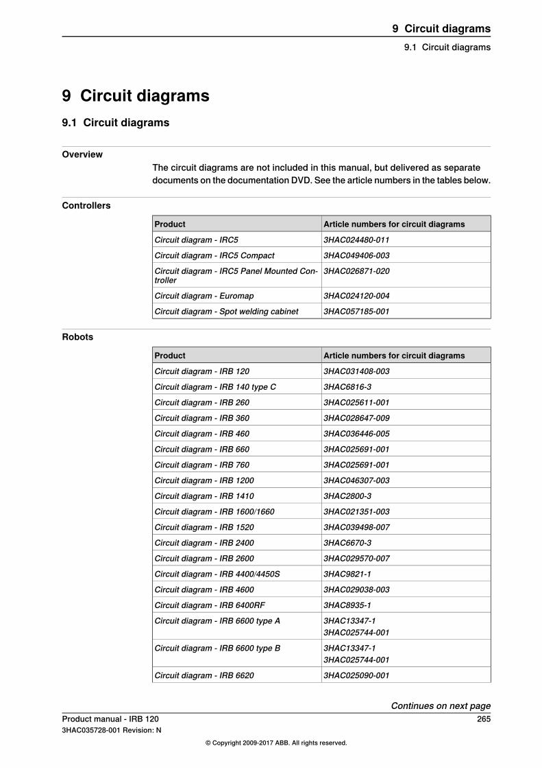
9 Circuit diagrams9.1 Circuit diagrams
OverviewThe circuit diagrams are not included in this manual, but delivered as separatedocuments on the documentation DVD. See the article numbers in the tables below.
Controllers
Article numbers for circuit diagramsProduct
3HAC024480-011Circuit diagram - IRC5
3HAC049406-003Circuit diagram - IRC5 Compact
3HAC026871-020Circuit diagram - IRC5 Panel Mounted Con-troller
3HAC024120-004Circuit diagram - Euromap
3HAC057185-001Circuit diagram - Spot welding cabinet
Robots
Article numbers for circuit diagramsProduct
3HAC031408-003Circuit diagram - IRB 120
3HAC6816-3Circuit diagram - IRB 140 type C
3HAC025611-001Circuit diagram - IRB 260
3HAC028647-009Circuit diagram - IRB 360
3HAC036446-005Circuit diagram - IRB 460
3HAC025691-001Circuit diagram - IRB 660
3HAC025691-001Circuit diagram - IRB 760
3HAC046307-003Circuit diagram - IRB 1200
3HAC2800-3Circuit diagram - IRB 1410
3HAC021351-003Circuit diagram - IRB 1600/1660
3HAC039498-007Circuit diagram - IRB 1520
3HAC6670-3Circuit diagram - IRB 2400
3HAC029570-007Circuit diagram - IRB 2600
3HAC9821-1Circuit diagram - IRB 4400/4450S
3HAC029038-003Circuit diagram - IRB 4600
3HAC8935-1Circuit diagram - IRB 6400RF
3HAC13347-1Circuit diagram - IRB 6600 type A3HAC025744-001
3HAC13347-1Circuit diagram - IRB 6600 type B3HAC025744-001
3HAC025090-001Circuit diagram - IRB 6620
Continues on next pageProduct manual - IRB 120 2653HAC035728-001 Revision: N
© Copyright 2009-2017 ABB. All rights reserved.
9 Circuit diagrams9.1 Circuit diagrams

Article numbers for circuit diagramsProduct
3HAC025090-001Circuit diagram - IRB 6620 / IRB 6620LX
3HAC025744-001Circuit diagram - IRB 6640
3HAC13347-1Circuit diagram - IRB 6650S3HAC025744-001
3HAC025744-001Circuit diagram - IRB 66603HAC029940-001
3HAC043446-005Circuit diagram - IRB 6700
3HAC13347-1Circuit diagram - IRB 76003HAC025744-001
3HAC050778-003Circuit diagram - IRB 14000
3HAC056159-002Circuit diagram - IRB 910SC
266 Product manual - IRB 1203HAC035728-001 Revision: N
© Copyright 2009-2017 ABB. All rights reserved.
9 Circuit diagrams9.1 Circuit diagramsContinued
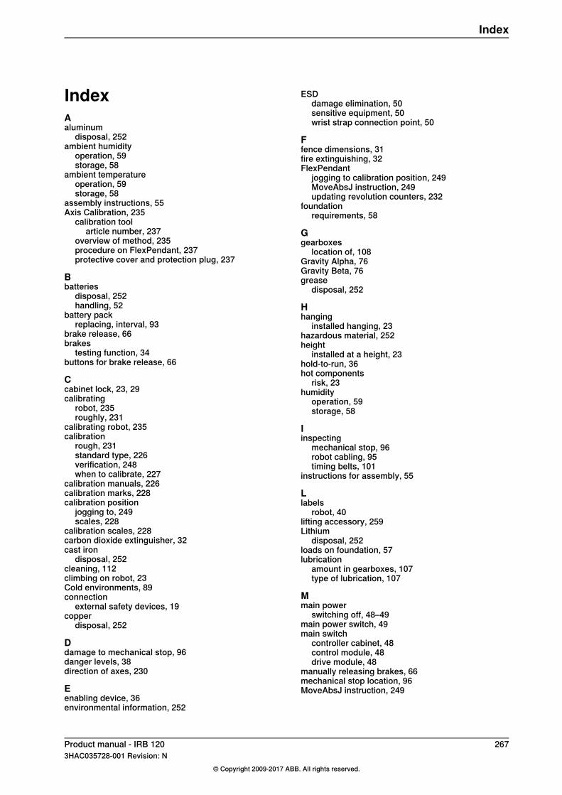
IndexAaluminum
disposal, 252ambient humidity
operation, 59storage, 58
ambient temperatureoperation, 59storage, 58
assembly instructions, 55Axis Calibration, 235
calibration toolarticle number, 237
overview of method, 235procedure on FlexPendant, 237protective cover and protection plug, 237
Bbatteries
disposal, 252handling, 52
battery packreplacing, interval, 93
brake release, 66brakes
testing function, 34buttons for brake release, 66
Ccabinet lock, 23, 29calibrating
robot, 235roughly, 231
calibrating robot, 235calibration
rough, 231standard type, 226verification, 248when to calibrate, 227
calibration manuals, 226calibration marks, 228calibration position
jogging to, 249scales, 228
calibration scales, 228carbon dioxide extinguisher, 32cast iron
disposal, 252cleaning, 112climbing on robot, 23Cold environments, 89connection
external safety devices, 19copper
disposal, 252
Ddamage to mechanical stop, 96danger levels, 38direction of axes, 230
Eenabling device, 36environmental information, 252
ESDdamage elimination, 50sensitive equipment, 50wrist strap connection point, 50
Ffence dimensions, 31fire extinguishing, 32FlexPendant
jogging to calibration position, 249MoveAbsJ instruction, 249updating revolution counters, 232
foundationrequirements, 58
Ggearboxes
location of, 108Gravity Alpha, 76Gravity Beta, 76grease
disposal, 252
Hhanging
installed hanging, 23hazardous material, 252height
installed at a height, 23hold-to-run, 36hot components
risk, 23humidity
operation, 59storage, 58
Iinspecting
mechanical stop, 96robot cabling, 95timing belts, 101
instructions for assembly, 55
Llabels
robot, 40lifting accessory, 259Lithium
disposal, 252loads on foundation, 57lubrication
amount in gearboxes, 107type of lubrication, 107
Mmain power
switching off, 48–49main power switch, 49main switch
controller cabinet, 48control module, 48drive module, 48
manually releasing brakes, 66mechanical stop location, 96MoveAbsJ instruction, 249
Product manual - IRB 120 2673HAC035728-001 Revision: N
© Copyright 2009-2017 ABB. All rights reserved.
Index
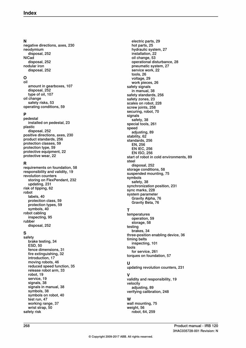
Nnegative directions, axes, 230neodymium
disposal, 252NiCad
disposal, 252nodular iron
disposal, 252
Ooil
amount in gearboxes, 107disposal, 252type of oil, 107
oil changesafety risks, 53
operating conditions, 59
Ppedestal
installed on pedestal, 23plastic
disposal, 252positive directions, axes, 230product standards, 256protection classes, 59protection type, 59protective equipment, 22protective wear, 22
Rrequirements on foundation, 58responsibility and validity, 19revolution counters
storing on FlexPendant, 232updating, 231
risk of tipping, 62robot
labels, 40protection class, 59protection types, 59symbols, 40
robot cablinginspecting, 95
rubberdisposal, 252
Ssafety
brake testing, 34ESD, 50fence dimensions, 31fire extinguishing, 32introduction, 17moving robots, 46reduced speed function, 35release robot arm, 33robot, 19service, 19signals, 38signals in manual, 38symbols, 38symbols on robot, 40test run, 47working range, 37wrist strap, 50
safety risk
electric parts, 29hot parts, 25hydraulic system, 27installation, 22oil change, 53operational disturbance, 28pneumatic system, 27service work, 22tools, 26voltage, 29work pieces, 26
safety signalsin manual, 38
safety standards, 256safety zones, 23scales on robot, 228screw joints, 258securing, robot, 70signals
safety, 38special tools, 261speed
adjusting, 89stability, 62standards, 256
EN, 256EN IEC, 256EN ISO, 256
start of robot in cold environments, 89steel
disposal, 252storage conditions, 58suspended mounting, 75symbols
safety, 38synchronization position, 231sync marks, 228system parameter
Gravity Alpha, 76Gravity Beta, 76
Ttemperatures
operation, 59storage, 58
testingbrakes, 34
three-position enabling device, 36timing belts
inspecting, 101tools
for service, 261torques on foundation, 57
Uupdating revolution counters, 231
Vvalidity and responsibility, 19velocity
adjusting, 89verifying calibration, 248
Wwall mounting, 75weight, 56
robot, 64, 259
268 Product manual - IRB 1203HAC035728-001 Revision: N
© Copyright 2009-2017 ABB. All rights reserved.
Index

Zzero position
checking, 249
Product manual - IRB 120 2693HAC035728-001 Revision: N
© Copyright 2009-2017 ABB. All rights reserved.
Index


ABB AB, RoboticsRobotics and MotionS-721 68 VÄSTERÅS, SwedenTelephone +46 (0) 21 344 400
ABB AS, RoboticsRobotics and MotionNordlysvegen 7, N-4340 BRYNE, NorwayBox 265, N-4349 BRYNE, NorwayTelephone: +47 22 87 2000
ABB Engineering (Shanghai) Ltd.Robotics and MotionNo. 4528 Kangxin HighwayPuDong DistrictSHANGHAI 201319, ChinaTelephone: +86 21 6105 6666
ABB Inc.Robotics and Motion1250 Brown RoadAuburn Hills, MI 48326USATelephone: +1 248 391 9000
www.abb.com/robotics
3HAC
0357
28-0
01,R
evN
,en


