Robotron: Top-down Network Management at Facebook Scale Yu-Wei Eric Sung, Xiaozheng Tie, Starsky H.Y. Wong, and Hongyi Zeng Facebook, Inc. [email protected]ABSTRACT Network management facilitates a healthy and sustain- able network. However, its practice is not well under- stood outside the network engineering community. In this paper, we present Robotron, a system for manag- ing a massive production network in a top-down fash- ion. The system’s goal is to reduce effort and errors on management tasks by minimizing direct human inter- action with network devices. Engineers use Robotron to express high-level design intent, which is translated into low-level device configurations and deployed safely. Robotron also monitors devices’ operational state to en- sure it does not deviate from the desired state. Since 2008, Robotron has been used to manage tens of thou- sands of network devices connecting hundreds of thou- sands of servers globally at Facebook. CCS Concepts •Networks → Network management; Keywords Robotron, Network Management, Facebook 1. INTRODUCTION “Lots of folks confuse bad management with destiny.” — Kin Hubbard Managing a large, dynamic, and heavily utilized net- work is challenging. Everyday, network engineers per- form numerous diverse tasks such as circuit turn-up and Permission to make digital or hard copies of all or part of this work for personal or classroom use is granted without fee provided that copies are not made or distributed for profit or commercial advantage and that copies bear this notice and the full citation on the first page. Copyrights for components of this work owned by others than the author(s) must be honored. Abstracting with credit is permitted. To copy otherwise, or republish, to post on servers or to redistribute to lists, requires prior specific permission and/or a fee. Request permissions from [email protected]. SIGCOMM ’16, August 22 - 26, 2016, Florianopolis , Brazil c 2016 Copyright held by the owner/author(s). Publication rights licensed to ACM. ISBN 978-1-4503-4193-6/16/08. . . $15.00 DOI: http://dx.doi.org/10.1145/2934872.2934874 migration, device provisioning, OS upgrade, access con- trol list modification, tuning of protocol behavior, and monitoring of network events and statistics. Network engineers highly value judicious network man- agement for several reasons. First, a properly config- ured network is a prerequisite to higher-level network functions. For example, routing protocols may not func- tion correctly if an underlying circuit is not provisioned as planned. Second, since network management tasks naturally involves human interactions, they are highly risky and can cause high-profile incidents [3, 8, 9]. Fi- nally, agile network management enables the network to evolve quickly, e.g., adding new devices or upgrading capacity, to support fast changing application needs. However, the field of network management is tradi- tionally considered too “operational” and therefore lacks published principles. Many challenges and lessons learned circulate only in the network engineering community. In practice, the time an engineer spends on the manage- ment plane can be much longer than the control and data planes. We outline challenges that we face in the management plane. Distributed Configurations: Translating high-level intent (e.g., provisioning decisions) into distributed low- level device configurations (configs) is difficult and error- prone due to the multitude of heterogeneous configura- tion options involved. For instance, migrating a circuit between routers can involve configuration changes in IP addressing, BGP sessions, interfaces, as well as “drain” and “undrain” procedures to avoid the interruption of production traffic. Multiple domains: Large Internet-facing services, such as Facebook, are often hosted on a “networks of networks,” where each sub-network has unique char- acteristics. For example, our network consists of edge points of presence (POPs), the backbone, and data cen- ters (DCs). The devices, topology, and management tasks vary per sub-network. Yet, all of them must be configured correctly in order for the entire network to function. Versioning: Unlike end-hosts which are statically connected to the top-of-rack switches, network topology
ABSTRACTNetwork management facilitates a healthy and sustain-able network. However, its practice is not well under-stood outside the network engineering community. Inthis paper, we present Robotron, a system for manag-ing a massive production network in a top-down fash-ion. The system’s goal is to reduce effort and errors onmanagement tasks by minimizing direct human inter-action with network devices. Engineers use Robotronto express high-level design intent, which is translatedinto low-level device configurations and deployed safely.Robotron also monitors devices’ operational state to en-sure it does not deviate from the desired state. Since2008, Robotron has been used to manage tens of thou-sands of network devices connecting hundreds of thou-sands of servers globally at Facebook.
CCS Concepts•Networks → Network management;
KeywordsRobotron, Network Management, Facebook
1. INTRODUCTION
“Lots of folks confuse bad managementwith destiny.” — Kin Hubbard
Managing a large, dynamic, and heavily utilized net-work is challenging. Everyday, network engineers per-form numerous diverse tasks such as circuit turn-up and
Permission to make digital or hard copies of all or part of this work for personalor classroom use is granted without fee provided that copies are not made ordistributed for profit or commercial advantage and that copies bear this noticeand the full citation on the first page. Copyrights for components of this workowned by others than the author(s) must be honored. Abstracting with credit ispermitted. To copy otherwise, or republish, to post on servers or to redistribute tolists, requires prior specific permission and/or a fee. Request permissions [email protected].
migration, device provisioning, OS upgrade, access con-trol list modification, tuning of protocol behavior, andmonitoring of network events and statistics.
Network engineers highly value judicious network man-agement for several reasons. First, a properly config-ured network is a prerequisite to higher-level networkfunctions. For example, routing protocols may not func-tion correctly if an underlying circuit is not provisionedas planned. Second, since network management tasksnaturally involves human interactions, they are highlyrisky and can cause high-profile incidents [3, 8, 9]. Fi-nally, agile network management enables the networkto evolve quickly, e.g., adding new devices or upgradingcapacity, to support fast changing application needs.
However, the field of network management is tradi-tionally considered too“operational”and therefore lackspublished principles. Many challenges and lessons learnedcirculate only in the network engineering community. Inpractice, the time an engineer spends on the manage-ment plane can be much longer than the control anddata planes. We outline challenges that we face in themanagement plane.
Distributed Configurations: Translating high-levelintent (e.g., provisioning decisions) into distributed low-level device configurations (configs) is difficult and error-prone due to the multitude of heterogeneous configura-tion options involved. For instance, migrating a circuitbetween routers can involve configuration changes in IPaddressing, BGP sessions, interfaces, as well as “drain”and “undrain” procedures to avoid the interruption ofproduction traffic.
Multiple domains: Large Internet-facing services,such as Facebook, are often hosted on a “networks ofnetworks,” where each sub-network has unique char-acteristics. For example, our network consists of edgepoints of presence (POPs), the backbone, and data cen-ters (DCs). The devices, topology, and managementtasks vary per sub-network. Yet, all of them must beconfigured correctly in order for the entire network tofunction.
Versioning: Unlike end-hosts which are staticallyconnected to the top-of-rack switches, network topology
Configuration-as-codeMinimal human input to create/update relevant objects in order to model desired network design;simple logic available in config templates using a template language; both config templates andgenerated configs are source controlled and rigorously reviewed (5.1, 5.2)
ValidationNetwork design constraints and rules embedded in FBNet models and network design tools (4, 5.1);assisted massive config deployment with human verification (5.3); ensure continuous network healththrough monitoring dynamic state and static config against desired network design (4, 5.4)
ExtensibilityVendor-neutral models are combined with objects expressing different generations of network archi-tecture and vendor-specific config templates to generate configs (4, 5.1, 5.2)
Table 1: High-level summary of Robotron’s design goals.
and routing design can change significantly over time indifferent parts of the network, requiring engineers tosimultaneously manage multiple “versions” of networksfor long periods of time. For example, Google’s datacenter networks have undergone five major upgrades ina 10-year span, each with different topologies, devices,link speeds, and configs [32].
Dependency: Configuring network devices involveshandling tightly coupled parameters. For example, toconfigure an iBGP full-mesh among all routers within asingle Autonomous System (AS), proper configurationmust exist in both peers of every iBGP session. Addinga new router into the AS means changing the configs onall other routers. Such dependencies are laborious fornetwork engineers to handle.
Vendor differences: Large production networks of-ten consist of devices from different vendors. Despite ef-forts to unify configuration options among multiple ven-dors [6,19], often the only way to take full advantage ofdevice capabilities is through vendor-specific command-line interfaces, configs, or APIs. Configuration options,protocol implementations, and monitoring capabilitiescan vary across vendor hardware platforms and OS ver-sions, making them extremely difficult to maintain.
To address these challenges, we designed and imple-mented Robotron, a system for managing large and dy-namic production networks. Robotron was designed toachieve the following goals, as summarized in Table 1:
Configuration-as-code: The best way to stream-line network management tasks is to minimize humaninteraction as well as the number of workflows. Hence,we codify much of the logic to ensure dependencies arefollowed and the outcome (device configs) is determin-istic, reproducible, and consistent.
Validation: To avoid config errors, we built differentlevels of validation into Robotron. For example, point-to-point IP addresses of a circuit are rejected if theybelong to different subnets. We include human verifi-cation, in some cases, as the last line of defense. Forinstance, before committing a new config to a device,the user is presented with a diff between the new andexisting config to verify all changes. After committing,we also employ continuous monitoring to closely trackthe actual network state.
Extensibility: Due to the tremendous growth of our
scaling needs, our network has constantly evolved, withnew device models, circuit types, DC and POP sites,network topologies, etc. We strive for generic systemdesign and implementation, while allowing network en-gineers to extend functionality with templates, tool con-figurations, and code changes. This allows us to focuson improving the system itself instead of being boggeddown by network changes.
With Robotron, we are able to minimize manual lo-gin to any network device for management tasks. Since2008, Robotron has been supporting Facebook’s pro-duction network, with tens of thousands of network de-vices connecting hundreds of thousands of servers glob-ally. Despite the multitude of deployed architecturesthroughout the years, Robotron’s core architecture hasremained stable and robust.
In this paper, we make the following contributions:(1) We describe the challenges of large-scale networkmanagement and give examples throughout the paperin the hope of motivating future research in this field.(2) We describe the design and implementation of Robotron,a system that employs a model-driven, top-down ap-proach to generate and deploy configs for tens of thou-sands of heterogeneous network devices in a large pro-duction network. In addition, Robotron monitors de-vice configs and operational states to ensure the net-work conforms to the model.(3) We report Robotron’s usage statistics, which pro-vide insights into real-world network management tasks.We also share our experiences using Robotron to man-age our network and discuss open issues.
2. THE NETWORK AND USE CASESThe term “network management” may involve many
different tasks depending on the situation. In this pa-per, network management means keeping track of thestate of network components (e.g., switches, IPs, cir-cuits) during their life cycle. 1Similar to many otherlarge Internet businesses, Facebook’s network is a “net-
1One framework for describing the network manage-ment space is Fault, Configuration, Accounting, Per-formance, and Security (FCAPS). [5] By this definition,Robotron covers configuration, as well as some account-ing management, with an emphasis on device and over-all topology modeling.
POPsInternet Backbone Data CentersUsers
Figure 1: The overview of Facebook’s network.
20G
Internet
PSWa PSWb PSWc PSWd
PR1
BB1 BB2
Agg
Core
ToTORsandservers
PR2
Figure 2: Example 4-post POP cluster. The dottedlines represent eBGP sessions [28].
work of networks” containing multiple domains: manyedge point-of-presence (POP) clusters, a global back-bone, and several large data centers (DC). The networkcarries both traffic to and from external users as well asinternal-only traffic. Let us navigate the network (Fig-ure 1) from the perspective of an external user as thatwill highlight each of the major domains of the networkand the common management tasks.
2.1 Point-of-PresenceThe production network managed by Robotron is re-
sponsible for fast and reliable delivery of large volumeof content to our users. When a user visits our ser-vice, the request travels to one of our globally-dispersededge POPs via the Internet. Our POPs typically con-tain a multi-tiered network as shown in Figure 2. Thefirst tier is Peering Routers (PRs), which connect toInternet Service Providers (ISPs) via peering and tran-sit links and to our backbone via Backbone Routers(BBs). From the PRs, connectivity to the POP serversis provided by a switching fabric that consists aggrega-tion switches (PSWs) and top-of-rack switches (TORs).Applications running on POP servers include load bal-ancers and caches. These POPs allow content to bestored closer to the end user, thereby reducing latency.Any request unable to be served by POP servers tra-verses our backbone network to one of the DCs.
Common POP management tasks include building anew POP, provisioning new peering or transit circuits,adjusting link capacity, and changing BGP configura-
FBNet DB
NetworkDesign
ConfigGeneration Deployment Monitoring
Figure 3: Overview of Robotron system.
tions (configs). Among these tasks, building a new POPis the most comprehensive and will be used as the run-ning example in Section 4 and 5.
2.2 Data CenterEach DC comprises a large number of machines host-
ing web servers, caches, databases, and backend ser-vices. These systems collectively generate a response tothe request, which is routed back to the user throughthe ingress POP. Each DC has several clusters, whoseexternal connectivity is provided by data center routers(DRs). Currently, there are several versions of clustersin production. These clusters have highly standardizedtopologies with tightly-coupled device configs. The con-figs for network devices in DCs change infrequently com-pared to those in the POPs or in the backbone.
Cluster provisioning jobs, which involve initial de-vice configuration, cabling assignment, IP allocation,etc, and cluster capacity upgrade are among the mostcommon management tasks happening in DCs.
2.3 BackboneThe backbone network provides transport among POPs
and DCs via optical transport links. Each backbone lo-cation consists of several BBs. From a protocol perspec-tive, both MPLS and BGP are used. We use PRs andDRs as edge nodes to set up label-switched paths viaBBs. MPLS traffic engineering (MPLS-TE) tunnels aredeployed for the purposes of traffic management. In ad-dition, internal BGP (iBGP) sessions are used betweenPRs and DRs to exchange routing information.
It is common to augment long-haul capacity acrossthe backbone network with circuit additions. This re-quires the generation and provisioning of IP interfaceconfiguration, including point-to-point addresses and bun-dle membership. Also, due to the mesh-like nature ofboth MPLS-TE tunnels and iBGP between DRs andPRs, the deployment/removal of a new node or modifi-cation to an existing node requires configuration changesto a large number of nodes within the topology.
3. ROBOTRON OVERVIEWAs with many companies, we heavily relied on manual
configuration and ad-hoc scripts to manage our networkin its early days. Since 2008, we have built FBNet, anobject store to model high-level operator intent, fromwhich low-level vendor-specific configs are generated,deployed, and monitored. We refer to this process as
“top-down” network management. Over the years, FB-Net and the suite of network management software webuilt around it have evolved to support an increasingnumber of network devices and network architectures,becoming what is known today as Robotron.
Figure 3 shows an overview of Robotron. Using FB-Net as the foundation, Robotron covers multiple stagesof the network management life cycle: network design,config generation, deployment, and monitoring.
FBNet: FBNet is the central repository for informa-tion, implemented as an object store, where each net-work component is modeled as an object. Object dataand associations are represented by attributes. For ex-ample, a point-to-point circuit is associated with twointerfaces. The circuit and interfaces are all objectsconnected via attributes of the circuit object. FBNetserves as the single source of truth for component state,used in the life cycle stages described below.
Network Design: The first stage of the manage-ment life cycle is translating the high-level network de-sign from engineers into changes to FBNet objects. Forexample, when designing a cluster, an engineer mustprovide high-level topology information, e.g., numberof racks per cluster, number of uplinks per top-of-rackswitch, etc. Robotron realizes the design in FBNet bycreating top-of-rack switch, circuit, interface, and IPaddress objects for the cluster.
Config Generation: After FBNet objects are popu-lated, the config generation stage builds vendor-specificdevice configs based on object states. Config genera-tion is highly vendor- and model-dependent. A set oftemplate configs, which are extended as new types ofdevices are put into production, enables FBNet to pro-vide the object states necessary for each build.
Deployment: Once device configs are generated, thenext stage is to deploy them to network devices. Correctand safe multi-device deployment can be challenging.Many design changes affect multiple heterogeneous de-vices. To reduce the risk of severe network disruptions,changes are deployed in small phases before reaching alldevices.
Monitoring: When a network component is in pro-duction, it must be continuously monitored to ensureno deviation from its desired state. This is a criticalpart of auditing and troubleshooting an active network.For example, all production circuits are monitored toensure they are up and passing traffic.
4. FBNET: MODELING THE NETWORKFBNet is the vendor-agnostic, network-wide abstrac-
tion layer that models and stores various network deviceattributes as well as network-level attributes and topol-ogy descriptions, e.g., routers, switches, optical devices,protocol parameters, topologies, etc. We empiricallyapproached the design of FBNet data models, influ-enced by our network architecture, network manage-ment tasks, and operational events. Our design goals
PR1PSWa
10G
10Get1/1
et1/2
et2/1
et3/1
ae0 ae12001::1 2001::2
eBGPsessionLinecardCircuit
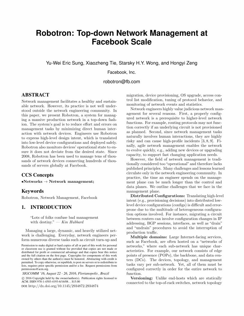
Figure 4: PSWa-PR1 portmap.
are two-fold. First, the data models should be simpleand comprehensive in order to capture common networkproperties across diverse device vendors, hardware plat-forms, circuit providers, etc. Second, the data modelsshould be easy to extend and maintain over time basedon management software needs.
In addition to the data models, FBNet provides APIsthat enable any application to query data and safelymake changes. FBNet’s data store and APIs are ar-chitected to be reliable, highly available, and scalableto high read rates. We describe the details of FBNetdata models, APIs, and architecture in the rest of thesection.
4.1 Data Model
4.1.1 Object, Value, and RelationshipA network in FBNet has physical (e.g., network de-
vices, linecards, physical interfaces, circuits) and logical(e.g., BGP sessions, IP addresses) components. Theyhave attributes to store component data and associa-tions between components. FBNet models these com-ponents, data attributes, and association attributes re-spectively as typed objects, value fields, and relation-ship fields. Every object is instantiated based on a datamodel that defines the type of the object and its avail-able fields. Value fields contain object data whereasrelationship fields contain typed references to other ob-jects.
To illustrate this idea, consider Figure 2 which de-picts a 4-post POP cluster topology. The cluster has agroup of four PSWs connected to the TORs and servers[not shown]. Each PSW has one 20G uplink to each ofthe two PRs. The PRs connect to the backbone viathe BBs and serve as gateways to the Internet throughpeering and transit interconnects. Routing informationis exchanged by external BGP (eBGP) sessions estab-lished between the PSWs and PRs, and the PRs andInternet Service Providers.
Figure 4 zooms into the connectivity between PSWaand PR1. The 20G point-to-point link is a logical bun-dle formed by grouping two 10G circuits in parallel.Each circuit has a 10G physical interface on each de-vice as its endpoints. Each physical interface resides ina linecard and is named etX/Y, where X indicates thelinecard’s slot number inside the device chassis, and Y is
name=PSWa
slot=1 model=X device=
name=et1/1 linecard= agg_interface=
name=et1/2 agg_interface= linecard=
name=ae0
prefix=2001::1 interface=
a_prefix= z_prefix=
name=ae1
prefix=2001::2 interface=
name=et3/1 agg_interface= linecard=
name=et2/1 linecard= agg_interface=
name=PR1
slot=2 model=Y device=
slot=3 model=Y device=
Networkswitch Linecard
PhysicalInterface
PhysicalInterface
AggregatedInterface AggregatedInterface
PhysicalInterface
PhysicalInterface
V6Prefix
BgpV6Session
V6Prefix
Linecard
Linecard BackboneRouter
a_endpoint= z_endpoint=
Circuit
Circuit a_endpoint=
z_endpoint=
Figure 5: FBNet models for Figure 4.
the port number on the linecard. The two physical in-terfaces on each device are combined into an aggregatedinterface (aeX) running Link Aggregation Control Pro-tocol (LACP) to load-balance traffic across interfacesin the group. Each aggregated interface is assigned anIP from the same /127 subnet. An eBGP session is es-tablished over the logical bundle to exchange routinginformation.
Figure 5 lays out how the connectivity is modeledin FBNet. The example’s network components (PSWa,PR1, physical interfaces, aggregated interfaces, linecards,circuits, IPs, and eBGP sessions) are represented bytyped objects with value and relationship fields. Rela-tionships are shown as directed edges capturing the as-sociations between objects (e.g., linecards are installedin a device chassis, physical interfaces are grouped intoan aggregated interface, an IP address is configuredper aggregated interface, circuits terminate at physi-cal interfaces, etc). Value fields have basic data typessuch as string, integer, etc. Objects can only be as-sociated with certain object types based on the rela-tionship field. For example, the PhysicalInterfacemodel has a string field name and a relationship fieldaggregated_interface that captures its many-to-oneassociation with the AggregatedInterface model.
While this example demonstrates a limited set of thecore models, the actual set is much richer. At the timeof this paper, there were over 250 models in total cover-ing IP/AS number allocations, optical transport, BGP,operational events, etc.
4.1.2 Desired versus DerivedFBNet models are partitioned into two distinct groups:
Desired and Derived.Desired models capture the desired network state,
which is maintained by network engineers with a setof specialized tools provided by Robotron. To makechanges, engineers modify the data to describe the up-dated network design instead of directly updating eachdevice config. The data is used to drive the generationof device configs. As a result, the integrity and accuracyof Desired model data is paramount to the correctnessof the generated configs.
Derived models reflect the current operational net-work state. In contrast to Desired models, data in De-
rived models is populated based on real-time collectionfrom network devices (Section 5.4). For example, a cir-cuit object is created if the Link Layer Discovery Proto-col (LLDP) data from two devices shows that the phys-ical interfaces connected to both ends are neighbors toeach other. One obvious use case of having the Desiredand Derived data is anomaly detection. Differences be-tween data in both models could imply expected or un-expected deviation from planned network design due toreasons such as unapplied config changes, or unplannedevents such as hardware failures, fiber cuts, or miscon-figurations.
While designing Desired and Derived models, we fol-low three main principles: (1) the models only containthe fields and data needed by the various managementtools; (2) both model groups may contain different at-tributes but should be as similar as possible to allow forsimple comparison (e.g., a PhysicalInterface modelexists in both model groups, but only the Derived ver-sion has the oper status attribute to indicate the cur-rent operational state of the interface); (3) duplicationof Desired model fields should be minimized due to thedifficulty of consistently maintaining multiple sources oftruth. For example, a physical interface object can beassociated with a device object indirectly via the devicefield of the corresponding linecard object. Adding a de-vice relationship field to the physical interface objectwould require two device fields to remain in sync witheach other.
4.2 APIs
4.2.1 Read APIsFBNet’s read APIs provide operations to retrieve a
list of objects and their attributes. The APIs have astandard declaration for each object type and are de-fined around fields and query as follows:
get<ObjectType>(fields, query)
fields: A list of value fields relative to the objectof the given type. A value field can be local to an ob-ject or indirectly referenced via one or more relationshipfields. For example, to get the slot and device name ofa linecard object, fields has two attributes, slot anddevice.name. In addition, for each relationship field, a
reverse connection is made available from the referencedobject 2 for convenient access to related objects. For ex-ample, a device object has a linecards field created asa result of the relationship field from the linecard model.query: Criteria that the returned list of objects must
match. A query is made of expressions. An expressionhas the form <field> <op> <rvalue> where field isthe local or indirect value field to compare to, op is thecomparison operator, and rvalue is a list of values tocompare against. Example operators are EQUAL, REG-EXP, etc. Multiple expressions can be composed usinglogical operators to form a large, complex query.
4.2.2 Write APIsIn contrast to per-object-type operations provided
by the read APIs, FBNet’s write APIs provide high-level operations that add, update, or delete multipleobjects to ensure data integrity (i.e., meets network de-sign rules). For example, one of the write APIs is de-signed for portmap manipulation (e.g., used to createthe portmap in Figure 4). The API takes a “changeplan” as the input including an old portmap and a newportmap, and carries out portmap creation, migration,update, deletion, etc, accordingly, while enforcing net-work design rules.
4.3 Architecture and ImplementationWe describe the distributed architecture of FBNet
and its API services, our implementation choices, andhow they scale and tolerate failures across multiple datacenters.
4.3.1 Storage LayerThe main pillars of FBNet models are objects and
relationships. This fact lends FBNet’s persistent ob-ject store to being implemented in MySQL, a relationaldatabase. Each FBNet model is mapped to a databasetable where each column corresponds to a field in themodel and each row represents an object. Relationshipfields correspond to foreign keys, establishing the logicalconnections between FBNet models.
We use Django [2], an object-relational mapping (ORM)framework in Python, to translate FBNet models intotable schemas. Figure 6 shows a snippet of FBNet mod-els. Using an ORM framework enables (1) quick modelchanges, (2) the use of object-oriented techniques suchas inheritance, (3) support of custom value fields andper-field validation, e.g., V6PrefixField.
4.3.2 Service LayerIn order for clients written in any programming lan-
guage to use FBNet APIs, both read and write APIs areexposed as language-independent Thrift remote proce-dure calls (RPC) utilizing Django’s ORM API to inter-act with the database.
2Reverse connections are added in API only, but not inactual FBNet models.
class PhysicalInterface(Interface):
linecard = models.ForeignKey(Linecard)
agg_interface = models.ForeignKey(
AggregatedInterface)
class V6Prefix(Prefix):
prefix = models.V6PrefixField()
interface = models.ForeignKey(Interface)
class V6PrefixField(CharField):
def get_prep_value(self, value):
# Check if value is a valid IPv6 Address
ip = ipaddr.IPNetwork(value)
if ip.version == 6:
return str(ip)
return ’’
Figure 6: Example FBNet models in Django.
The standard declaration of FBNet’s read API perobject type allows the Thrift API definition to be auto-generated by introspecting FBNet models. The readAPI service translates incoming RPC calls into efficientORM calls to query the database, and serializes the re-sults back to the caller as a list of Thrift objects. When-ever FBNet models are changed, the service just needsto be re-packaged and re-deployed to expose the up-dated APIs.
FBNet’s write API service defines and implementsdifferent APIs for different use cases. To ensure theatomicity, each write API is wrapped in a single databasetransaction, and therefore no partial state is visible toother applications before the API call completes suc-cessfully. If an error occurs, all previous operations inthe transaction are rolled back.
4.3.3 Scalability and AvailabilityApplications perform reads and writes through the
service layer from multiple, geographically-diverse DCs.We employ standard MySQL replication using one mas-ter and multiple slaves, one per DC. All writes to themaster database server are replicated asynchronously tothe slave servers with a typical lag of under one second.Each database server is fronted with multiple write andread API service replicas deployed locally. While writesmust be forwarded to the write API service in the mas-ter database region, client read requests can be servicedlocally to reduce latency. Read service replicas are alsodeployed for the master database to support clients re-quiring read-after-write consistency.
FBNet can recover from two common failures.Database Failures: A database is disabled if it con-
sistently fails health-checks. In addition, a slave is alsodisabled when it experiences high replication lag. Whenthe master goes down, the slave in the nearest data cen-ter is promoted to master. The new master handlesall reads/writes originally destined for the old master.When a slave fails, service replicas in the same datacenter temporarily redirect their reads to the masterdatabase until the slave recovers.
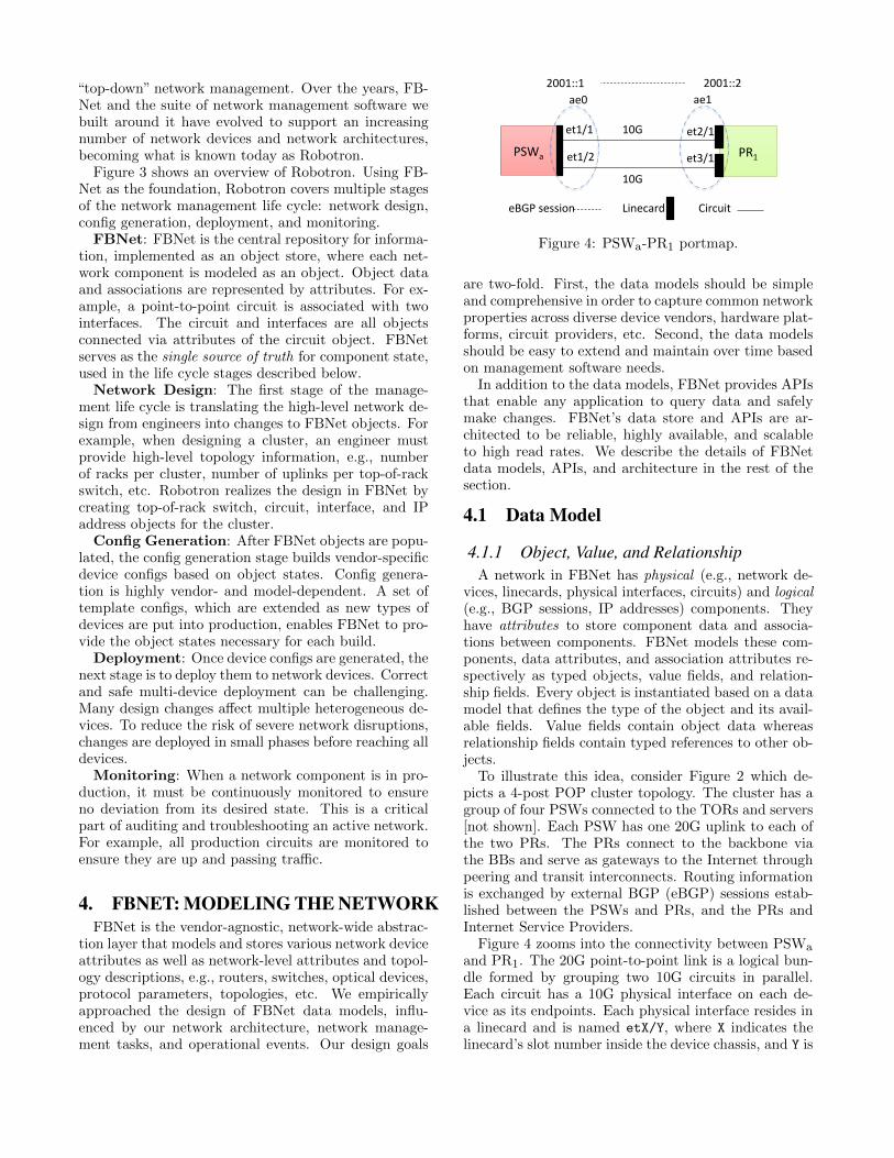
Figure 7: Robotron materializes a cluster template intoFBNet objects.
Service Replica Failures: When an API servicereplica fails due to process crash or server failure, re-quests are redirected to any remaining service replicasin the same data center. If they are also down, re-quests are rerouted to the nearest live service replicasin a neighboring data center.
5. MANAGEMENT LIFE CYCLEUsing FBNet as the foundation, Robotron’s manage-
ment life cycle has four stages: network design, configgeneration, deployment, and monitoring.
5.1 Network DesignIn this stage, Robotron consumes high-level, human-
specified network designs, which are validated againstnetwork design rules, and translates them into DesiredFBNet objects filled with values and relationships.
5.1.1 POPs and DCsPOPs and DCs have standard fat-tree architectures
that change rarely after the initial turn-up. Such a uni-form architecture lends itself to be captured with topol-ogy templates. A topology template defines componentsthat compose a topology: network devices and groups oflinks (link group) that connect them. Recall the exam-ple POP cluster in Figure 2 that contains four PSWs,each connecting to two PRs. Figure 7 shows the corre-sponding topology template. It defines (1) the devices’hardware profiles (e.g., vendor, linecards, interfaces re-served for each neighboring device), (2) the number ofdevices of each type, e.g., two PRs each with hardwareprofile Router_Vendor1, (3) how they are connected,e.g., each (PR, PSW) pair is connected by a link bun-dle with 2 circuits, and (4) IP addressing scheme.
Given these templated designs, Robotron creates FB-Net objects accordingly. In this case, Robotron con-structs 2 BackboneRouter objects and 4 NetworkSwitchobjects, representing the PRs and PSWs, respectively.In addition, each (PR, PSW) pair has a portmap similarto Figure 4. In total, 94 objects of various types (e.g.,Circuit, BgpV6Session) are created in FBNet as seen
in Figure 7. Robotron also establishes the relationshipsof each object, e.g., associating physical interfaces withaggregated interfaces, circuits with physical interfaces,prefixes with aggregated interfaces, and BGP sessionswith prefixes.
Using topology templates allows us to easily extendRobotron to support different network architectures.Over the years we have built hundreds of POP and DCclusters which have undergone several major architec-ture changes. These templates are also used by net-work engineers to try different topology designs such asadding more devices, device types, and links, forklift-ing upgrades to newer hardwares or different vendors.Robotron is able to translate these designs to tens ofthousands of FBNet objects within minutes.
5.1.2 BackboneIn contrast to POP and DC networks, our backbone
network employs a constantly changing asymmetricalarchitecture in order to adapt to dynamic capacity needs.Most design changes result from incrementally addingand deleting backbone routers, as well as adding, mi-grating, and deleting circuits between routers to addmore redundancy and capacity. Each month, we per-form tens of router additions and deletions, and hun-dreds of circuit additions, migrations and deletions.
Robotron provides device and circuit design tools forthese incremental changes. The tools provide high-levelprimitives to users and do complex object validationand manipulation in the backend. For example, userscan issue the “delete” command with a router name asparameter, and the device tool automatically handlesdeleting the corresponding FBNet router object anddeleting or disassociating its related objects.
A key challenge of supporting incremental changesis to resolve object dependency. For example, addingand removing a backbone router requires updating theiBGP mesh by modifying BGP session objects relatedto all other routers on the edge of the backbone; mi-grating a circuit from one router to another requiresdeleting or re-associating existing interface, prefix, andBGP session on one router and creating new ones onthe other.
Robotron leverages FBNet’s object relationships totrack and resolve object dependency when making de-sign changes. When updating an object, it checks allits related objects through relationship fields and up-dates them accordingly. In the above circuit migrationexample, Circuit model has a foreign key to Physi-calInterface, and the latter has a reverse relationshipto V6Prefix (Figure 5, 6). When a circuit object isdisconnected by removing its association with physicalinterfaces, Robotron follows the relationship to deletethe prefix objects associated with the old physical in-terfaces before clearing the relationship fields.
5.1.3 Design ValidationNetwork design errors are a major cause of network
struct Device {
1: list<AggregatedInterface> aggs,
}
struct AggregatedInterface {
1: string name,
2: i32 number,
3: string v4_prefix,
4: string v6_prefix,
5: list<PhysicalInterface> pifs,
}
struct PhysicalInterface {
1: string name,
}
Figure 8: A snippet of Thrift data schema for configgeneration.
outage: one could specify incomplete and incorrect de-signs like missing or incorrect device and link specifica-tion in the template, or assigning duplicate endpointsto a circuit. Robotron takes both automatic and man-ual validation approaches to prevent errors. First, itembeds various rules to automatically validate objectswhen translating template and tool inputs to FBNetobjects. These rules check object value and relation-ship fields to ensure data integrity (e.g., a circuit mustbe associated to two physical interfaces), and avoid du-plicate objects. Second, Robotron displays the result-ing design changes and requires users to visually reviewand confirm before committing the change to FBNet.Third, it requires employee ID and ticket ID to trackdesign change history. Finally, Robotron logs all designchanges for ease of debugging and error tracking.
5.2 Config GenerationIn this stage, Robotron leverages relevant FBNet ob-
jects created in the network design stage to generatevendor-specific device configs. To address the challengethat different vendors use different proprietary config-uration languages, Robotron divides a device configu-ration into two parts: dynamic, vendor-agnostic datasuch as names and IP addresses, and static, vendor-specific templates with special syntax and keywords.The former is derived from FBNet objects and stored asa Thrift [1] object per device according to a pre-definedschema while the latter is stored as flat files.
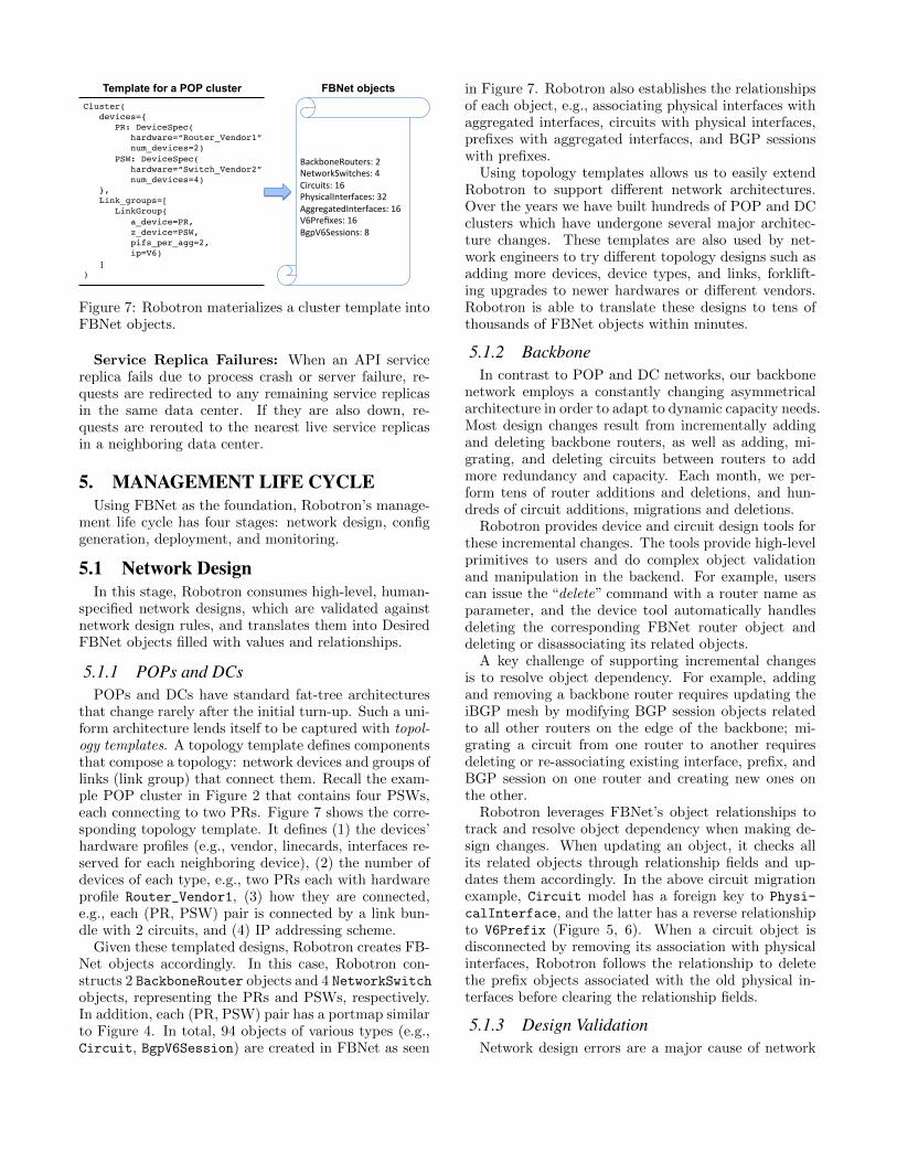
Figure 8 and Figure 9 are snippets of the config’sdata schema and templates for two vendors. Figure 8defines the structured schema for device, aggregated in-terface, physical interface, and their attributes that willbe used in all config templates. Figure 9 shows the inter-face config templates for our PSW and PR devices fromtwo different vendors. Utilizing Django’s template lan-guage, dynamic variables and control flows are respec-tively surrounded by {{}} and {%%}, and static contentis left as plain text. Figure 9 shows that the two vendorsuse different configuration syntax to group physical in-terfaces to aggregated interface and assign IPs, yet theyshare common variables such as interface names and IPprefixes, and a common control flow such as they both
{% for agg in device.aggs %}interface {{agg.name}}mtu 9192no switchportload-interval 30{% if agg.v4_prefix %}ip addr {{agg.v4_prefix}}{% endif %}{% if agg.v6_prefix %}ipv6 addr {{agg.v6_prefix}}{% endif %}no shutdown
{% for agg in device.aggs %}replace: {{agg.name}} {unit 0 {{% if agg.v4_prefix %}family inet {addr {{agg.v4_prefix}};
}{% endif %}{% if agg.v6_prefix %}family inet6 {addr {{agg.v6_prefix}};
}{% endif %}
}}{% for pif in agg.pifs %}replace: {{pif.name}} {gigether-options {802.3ad {{agg.name}};
}}{% endfor %}
{% endfor %}
Figure 9: Interface config templates for PSW (left) andPR (right) from two vendors.
Vendor1 Vendor2
ConfigThri0Schema
interfacetemplate
BGPtemplate
MPLStemplate…
interfacetemplate
BGPtemplate
MPLStemplate…
PR1 PR2
PSWa PSWb PSWc PSWd
FBNet
PR1 PSWa
PSWc
PR1config
PR2config
PSWaconfig PSWbconfig
PSWcconfig PSWdconfig
PSWb
PSWd
PR2
FBNetobjects
Thri0objects
Vendor-specificConfigs
Figure 10: Config generation from FBNet objects.
iterate over all aggregated and physical interfaces.As shown in Figure 10, Robotron generates configu-
ration in a few steps. First, for a given location suchas a POP or DC, Robotron fetches all related objectsfrom FBNet. Second, for each device, Robotron derivesrelevant device-specific data from FBNet objects (e.g.,data for a device interface depends on the FBNet cir-cuit object the interface connects to), stores it into aThrift object. Finally, Robotron combines the Thriftobject with vendor-specific templates to generate theconfig for the device.
Config correctness ensures healthy network operationand Robotron takes multiple measures to minimize con-fig errors. First, it stores config data schemas and tem-plates in Configerator [37], a source control repository,so that all schema and template changes are peer-reviewedand unit-tested. Second, it backs up the running con-figs for all network devices for quick restoration duringcatastrophic events. Finally, Robotron monitors run-ning config changes and fires alerts for changes that de-viate from Robotron-generated configs (Section 5.4.3).
5.3 DeploymentOnce the configs are generated, network engineers de-
ploy them using a CLI. The ultimate goal is agile, scal-able, and safe deployment while minimizing the risk ofnetwork outages. Robotron supports two different sce-narios: initial provisioning and incremental updates.
5.3.1 Initial ProvisioningInitial provisioning is used when the devices are in a
clean state, such as turning up all switches in a new clus-ter. In this case, Robotron erases old configurations (ifthey exist) and copies new configurations to the devices,followed by basic validations (e.g., checking connectiv-ity). Initial provisioning is relatively simple. Startingfrom a clean state also reduces the chance for errors.One restriction is that network devices must be com-pletely “drained” of any traffic.
5.3.2 Incremental UpdatesIn contrast, incremental updates occur when an on-
line device requires incremental changes, such as addingcircuits for additional capacity. In this case, Robotronusually applies configurations to more than one live de-vice, with only a portion of the running configuration ineach device affected. To minimize the impact of thesechanges, Robotron employs multiple mechanisms:
Dryrun Mode: New configs are compared againstthe current running configs, if natively supported by thedevices. Users receive and review a diff listing all up-dated lines from the new configurations for unexpectedchanges. Dryrun can also detect most errors from in-valid configurations and vendor bugs. For devices thatdo not support native dryrun, a diff will still be gener-ated for review by comparing the running configs beforeand after deployment.
Atomic Mode: Engineers often need to deploy newconfigs to multiple devices (e.g., iBGP mesh updates).For these operations, configs may need to be committedto the devices in one atomic transaction for the networkto operate correctly. Robotron allows engineers to spec-ify whether the deployment should be atomic. Duringan atomic update, if any of the devices experiences er-rors or cannot finish applying the config within a giventime window, Robotron rollbacks the entire transaction.
Phased Mode: To prevent errors affecting opera-tions from propagating throughout the network, somedeployments, such as firewall rule changes, require ap-plying new configurations in multiple phases. In phaseddeployments, engineers specify a permutation of per-centage/region/role of devices to be updated in eachphase. Robotron monitors metrics to track the progressof each phase and only continues deployment if the pre-vious phase is successful or engineers will get a notifi-cation from Robotron upon failures.
Human Confirmation: For certain cases, engineerscan verify expected network behavior within a grace pe-riod after roll-out. During this timeframe, new configu-
XML SNMP CLIThriftEngines
JobManager
FBNet HBase HiveBackendsDevices
Figure 11: Robotron’s active monitoring pipeline is di-vided into 3 tiers: job manager, engines, and backends.
rations are temporarily committed to the devices whereengineers can conduct ad-hoc verification. A final con-firmation must be provided during the grace period oth-erwise Robotron will rollback the changes.
5.4 MonitoringTo ensure the continuous health of the network, Robotron
employs three main monitoring mechanisms: passivemonitoring, active monitoring, and config monitoring.
5.4.1 Passive MonitoringPassive monitoring detects operational events such as
running configuration changes, route flaps, and devicereboots. Syslog [23] is our main passive monitoring in-terface due to wide support by vendors. In our passivemonitoring pipeline, each device is configured to sendsyslog messages to a BGP anycast address. Multipleclassifiers collect these messages from the anycast ad-dress based on a set of regular expression rules main-tained by network engineers. A syslog message match-ing a rule triggers the corresponding alerts which areremediated automatically or manually by engineers.
5.4.2 Active MonitoringWe use active monitoring to collect performance met-
rics (e.g., link, CPU, and memory utilization) and de-vice states which can be used for cases such as populat-ing FBNet Derived models. Figure 11 shows the threemajor tiers of this pipeline.
Specifically, the Job Manager schedules periodic mon-itoring jobs based on a list of job specifications, each ofwhich describes the collection period, the type of data,the devices, and the storage backends the data shouldbe sent to. Job manager can also create ad-hoc moni-toring jobs on-demand. The Engines pull jobs from theJob Manager directly and poll data from the networkdevices accordingly. There are multiple different en-gines using different polling mechanisms such as SNMP,XML/RPC, CLI and Thrift. Backends receive the col-lected data and convert it into a format appropriate fordifferent storage locations.
5.4.3 Config MonitoringRobotron leverages both passive and active monitor-
ing to monitor the running configuration of devices.When a running config is updated, a syslog messageis generated and captured by our passive monitoring
0
0.2
0.4
0.6
0.8
1# o
f cl
ust
ers
(norm
aliz
ed)
Time
Gen2Gen1
(normalized)
(a) POP
0
0.2
0.4
0.6
0.8
1
# o
f clu
ste
rs (
norm
aliz
ed)
Time
Gen3V6Gen3
Gen2V6Gen2-DGen2-CGen2-BGen2-A
Gen1
(b) DC
Figure 12: Evolution of cluster architectures.
pipeline. The message then triggers an active moni-toring job which collects the running config, comparesit with Robotron-generated “golden” configuration, andnotifies the engineers of any discrepancy. A config changeis typically detected within minutes. Each collectedrunning config is also backed up in a revision controlsystem to track the history of each device config. Theconfig monitoring framework ensures (1) the continu-ous conformance of device configs to their golden con-figs throughout our network and (2) the engineers canrollback to any prior device config upon disasters.
6. USAGE STATISTICSFacebook’s network evolves in a hybrid and dynamic
fashion. The backbone network constantly experiencesorganic growth and changes in size, circuit speed, andits mesh topology. DC and POP networks, already hav-ing multiple architectures, underwent several major up-grades.
Figure 12 shows the evolution of our POP and DCarchitecture over the last two years. Originally, the de-ployment of Gen1 POP clusters rapidly grew to serveincreasing user traffic. But over a few months, theywere quickly merged into bigger Gen2 POP clustersto improve efficiency and manageability. Contrastingwith the simplicity of POP architecture, our DC clus-ters went through three architecture generations, eachwith multiple topologies. Additionally, the exhaustionof the private IPv4 address space required newer clus-ters to only support IPv6. Multiple generations of DCarchitecture had to co-exist because unlike POP clus-ters, where architectural upgrades were completed in-place due to space/power limitation in POPs, architec-tural shifts for DC clusters took place by adding newand decommissioning previous generations of clusters.The life cycle of a DC cluster could end due to shiftsin space/power, changes in service requirements, and
0
0.2
0.4
0.6
0.8
1
0 5 10 15 20 25 30CD
F a
cro
ss m
od
els
# of related models
Figure 13: The number of related models associatedwith each FBNet model.
Time0
100
200
300
400
500
600
700
# o
f Li
nes
Per
Week
Figure 14: Desired model changes.
server hardware refreshes. Robotron ensures our net-work can evolve and support these architectures withminimal disruption to traffic.
In the remaining sections, we present usage statis-tics from various parts of Robotron. Unlike a typi-cal system evaluation, our focus is not on the systemperformance such as task completion time, due to thehighly implementation- and workflow-dependent natureof these metrics. Instead, we focus on Robotron usagestatistics to realize various network management tasks.
6.1 FBNet ModelsFBNet models dependency of network components
by association. For example, Circuit model is asso-ciated with PhysicalInterface model, and the latteris associated with AggregatedInterface model (Fig-ure 5). Figure 13 shows the number of related modelsassociated with each FBNet model. We can observethat around 60% of models have more than 5 relatedmodels. Closely modeling these dependencies allows usto ensure data integrity in FBNet.
We also want to understand the frequency of changesmade by engineers to the FBNet models. Django storesall models in multiple models.py files, whose historiesare maintained in a version control system. Figure 14depicts the total number of lines changed per week overa 3-year period for the Desired model group.
Many people would assume that the models shouldbecome stable after several weeks in production, but ourobservations record more than 50 lines changed, on av-erage, daily. Occasionally, large refactoring efforts cantouch hundreds of lines of code. Unfortunately, it is dif-ficult to classify each change programmatically. Basedon our discussion with network engineers as well as man-
0
0.25
0.5
0.75
1
1 10 100 1,000 10,000
CD
F ac
ross
des
ign
chan
ges
# of FBNet objects
AllInterface
Circuitv6 Prefixv4 Prefix
Device
(a) POP and DC
0
0.25
0.5
0.75
1
1 10 100 1,000 10,000
CD
F ac
ross
des
ign
chan
ges
# of FBNet objects
AllInterface
Circuitv6 Prefixv4 Prefix
Device
(b) Backbone
Figure 15: Number of changed FBNet objects acrossdesign changes.
ually analyzing some examples, we found that modelschange for several reasons:
New Component Types: This is the most obvi-ous reason for changes. New components result in cre-ation of new models. Moreover, a component defined inFBNet does not necessarily correspond to the physicalcomponent. For example, we created the BGPV4Sessionmodel to capture BGP sessions during the transitionfrom Gen1 (L2) to Gen2 (L3 BGP) DC clusters.
New Attributes: FBNet models are not, at incep-tion, all-inclusive. They only capture the attributes en-gineers value or require at that moment. As a result,new attributes are constantly added to existing mod-els as needed. In addition, the attributes may or maynot correspond to a direct configuration/command. Forexample, the drain_state attribute, a purely “opera-tional state”, is added to backbone routers to denotewhether the router is serving production traffic.
Logic Changes: Some attributes are not directlystored in FBNet. Instead, they are generated system-atically on the fly. The derivation logic may change asour understanding of the use cases matures. For exam-ple, a router has an attribute asset_url which pointsto a web page showing the device’s asset managementdetails. The logic that generates this URL evolves overtime along with our asset management system.
ious design changes. A design change is an atomic op-eration that stores a human-specified change to FBNet.It can be as simple as migrating a single circuit or ascomplex as building an entire cluster. Robotron takesminimum human specification as input and automati-cally handles the creation, modification, and deletion ofFBNet objects for each design change.
Figure 16: Weekly configuration changes during a 3-month period. Each sample represents one device in aparticular week.
Figure 15 compares the number of changed FBNetobjects, i.e., those that are created, modified, and deletedacross all design changes over one year. First, a designchange usually has high fan-out, changing from a fewobjects to 10,000 objects. Second, designs in POP andDC change more objects than in backbone, for exam-ple, the median number of all changed objects is 120for POP and DC networks in Figure 15(a) and is 20 forbackbone network in Figure 15(b). This is because theformer is usually one-time building of an entire clusterand the latter is mostly incremental and partial deviceand circuit changes. Third, the figure also breaks downthe result into different object types, among which in-terface objects are changed most frequently, followed bycircuit, v6 prefix, v4 prefix, and device objects. Notethat v6 prefix is changed more than v4 prefix as wemove toward v6-only clusters.
6.3 Configuration ChangeFigure 16 shows the weekly configuration changes dur-
ing a 3-month period. Each sample represents total up-dated config lines (changed/added/removed, excludingcomments) on a device in a particular week. We countPRs and DRs as backbone devices since they are usu-ally updated along with BBs, unlike POP/DC devices.For example, 90% of backbone device samples have lessthan 500 updated lines per week, while only 50% ofPOP/DC samples are of the same size.
Beyond weekly aggregated metrics shown in Figure 16,we also observe that while changes are smaller on back-bone devices (157.38 lines updated per change on av-erage versus 738.09 on POP/DC devices), they havea greater number applied (12.46 changes per week onaverage versus 2.53 on POP/DC devices). This is con-sistent with Section 5.1 as we update backbone devicesincrementally, while our network devices in POPs andDCs are usually configured from a clean state. UnlikePOP/DC devices, operating backbone devices requirescontinuous live re-configurations, which benefit greatlyfrom Robotron’s config generation and deployment.
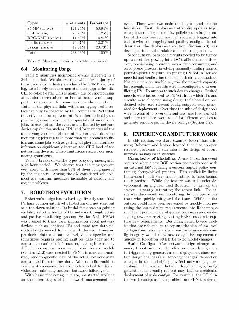
6.4 Monitoring UsageTable 2 quantifies monitoring events triggered in a
24-hour period. We observe that while the majority ofthese events use industry standards like SNMP and Sys-log, we still rely on other non-standard approaches likeCLI to collect data. This is mainly due to shortcomingsof standard mechanisms, or lack of better vendor sup-port. For example, for some vendors, the operationalstatus of the physical links within an aggregated inter-face can only be collected by CLI commands. Note thatthe active monitoring event rate is neither limited by theprocessing complexity nor the quantity of monitoringjobs. In our system, the event rate is limited by networkdevice capabilities such as CPU and/or memory and theunderlying vendor implementation. For example, somemonitoring jobs can take more than ten seconds to fin-ish, and some jobs such as getting all physical interfacesinformation significantly increase the CPU load of thenetworking devices. These limitations restrict our mon-itoring granularity.
Table 3 breaks down the types of syslog messages ina 24-hour period. We observe that the messages arevery noisy, with more than 95% of them being ignoredby the engineers. Among the 5% considered valuable,most are warning messages incapable of causing anymajor problems.
7. ROBOTRON EVOLUTIONRobotron’s design has evolved significantly since 2008.
Perhaps counter-intuitively, Robotron did not start outas a top-down solution. Its initial focus was on gainingvisibility into the health of the network through activeand passive monitoring systems (Section 5.4). FBNetwas created to track basic information about networkdevices such as loopback IPs and store raw data pe-riodically discovered from network devices. However,per-device data was too low-level, vendor-specific, andsometimes requires piecing multiple data together toconstruct meaningful information, making it extremelydifficult to consume. As a result, basic Derived models(Section 4.1.2) were created in FBNet to store a normal-ized, vendor-agnostic view of the actual network stateconstructed from the raw data. Ad-hoc audits could beeasily written against Derived models to look for designviolations, misconfigurations, hardware failures, etc.
With basic monitoring in place, we started workingon the other stages of the network management life
cycle. There were two main challenges based on userfeedbacks. First, deployment of config updates (e.g.,changes to routing or security policies) to a large num-ber of devices was still manual, requiring logging intoeach device and copying and pasting configs. To ad-dress this, the deployment solution (Section 5.3) wasdeveloped to enable scalable and safe config rollout.
Second, many backbone circuits needed to be turnedup to meet the growing inter-DC traffic demand. How-ever, provisioning a circuit was a time-consuming anderror-prone process, involving manually finding unusedpoint-to-point IPs (through pinging IPs not in Derivedmodels) and configuring them on both circuit endpoints.Not only were we unable to grow the network capacityfast enough, many circuits were misconfigured with con-flicting IPs. To automate such design changes, Desiredmodels were introduced to FBNet, from which IPs andcircuits were allocated using design tools based on pre-defined rules, and relevant config snippets were gener-ated for deployment. Over time the suite of design toolswere developed to cover different use cases (Section 5.1),and more templates were added for different vendors togenerate vendor-specific device configs (Section 5.2).
8. EXPERIENCE AND FUTURE WORKIn this section, we share example issues that arise
using Robotron and lessons learned that lead to openresearch problems or can inform the design of futurenetwork management systems.
Complexity of Modeling: A user-impacting eventoccurred when a new BGP session was provisioned withan external ISP requiring a custom import policy con-taining cherry-picked prefixes. This artificially limitsthe session to only serve traffic destined to users behindthose prefixes. While the feature was still under de-velopment, an engineer used Robotron to turn up thesession, instantly saturating the egress link. The is-sue was discovered, via monitoring, by our operationsteam who quickly mitigated the issue. While similaroutages could have been prevented by quickly incorpo-rating the latest design requirements into Robotron, asignificant portion of development time was spent on de-signing new or correcting existing FBNet models to cap-ture new requirements. Designing network-wide mod-els that are rich enough to capture the slew of low-levelconfiguration parameters and ensure cross-device con-fig integrity would allow new designs be implementedquickly in Robotron with little to no model changes.
Stale Configs: After network design changes aremade, Robotron currently relies on network engineersto trigger config generation and deployment since cer-tain design changes (e.g., topology changes) depend onchanges in the underlying physical network (e.g., re-cabling). The time gap between design changes, configgeneration, and config roll-out may lead to accidentaldeployment of stale configs. For example, the DC clus-ter switch configs use rack profiles from FBNet to derive
Urgency # of events Percentage # of rules Examples
CRITICAL 2 <0.01% 13 Critical Power/Temperature Alarm, Device Reboot, SSL VPN AlarmMAJOR 1.35K <0.01% 214 High Temperature Alarm, TCAM Errors, Linecard RemovedMINOR 32K 0.06% 310 TCAM Exhausted, Possible Bad FPC, IP conflictWARNING 1.8M 3.65% 103 SSL connection limit, Syslog cleared by user, Interface link state downNOTICE 6.68K 0.01% 79 DHCP Snooping Deny, MAC Conflict, Cannot find NTP serverIGNORED 47.5M 96.27% 0 LSP change, User authentication
Table 3: Syslog messages of various urgency levels collected in a 24-hour period. A “rule” refers to a regex rule inSection 5.4.3.
the number of downlink interfaces allocated per rack. Inone instance, Engineer A wanted to add a new rack to acluster. He updated the rack profile and generated con-figs for the cluster switches, but did not immediatelydeploy them. A few days later, Engineer B updatedthe rack profile, which invalidated A’s design change,but did not re-generate new configs accordingly. Oneweek later, Engineer A, unaware of the design changeEngineer B made, pushed the stale configs to the clus-ter switches, dropping connectivity to a few racks inthe cluster. While this particular issue could have beenavoided if network design, config generation and de-ployment were tightly coupled, the real challenge occurswhen design changes are made closely in time. How toserialize concurrent design changes, resolve design con-flicts, and leverage the Derived network state to ensurechange safety remains an open problem. Statesman [33]provides some novel ideas on conficts resolution. How-ever, at Facebook’s scale, handling multiple writers witha lock-based mechanism can be challenging.
Automation Fallbacks: Network engineers occa-sionally bypass Robotron to manually configure devices.This is due to Robotron bugs, unfamiliarity with Robotron,or the urgent need to make changes unsupported byRobotron. Manual changes often lead to misconfig-uration, resulting in issues such as idle circuits, sub-optimal routing, and unexpected outages. Ideally, anautomated network management system like Robotronshould block manual changes directly to the networkdevices and require all config changes be made throughit. However, our operational experiences show thatusers, especially in exceptional cases, usually need a re-liable fallback mechanism to make emergency changesto the network. Instead of blocking manual changes,Robotron curtails them with config monitoring (Sec-tion 5.4.3). Another possible solution is to restore de-vice running configs to Robotron-generated configs pe-riodically, while giving users a window for these emer-gency operations.
9. RELATED WORKSMany prior research focus on understanding network
management challenges, as well as reverse-engineeringand validating network designs through bottom-up staticconfiguration analysis in two classes of networks: providernetworks [15,20,25,29,36] and enterprise networks [13,14, 16, 26, 30]. In addition, recent work [21, 22] proposegeneral methods to analyze and troubleshoot configu-
rations. In contrast, Robotron employs a top-down ap-proach, which is continuously refined through opera-tional experience of our network engineers, to managea multi-domain network consisting of a backbone, mul-tiple DC and POP networks.
The potential of automating or simplifying networkdesign and configuration through abstraction has in-spired many works in the research community. A classof literature [31,34,35,38] applies the“top-down”paradigmto systematically optimize configuration of specific pro-tocols or network functions (e.g., VLANs, packet filters,topologies, and routing) to meet desired objectives suchas performance, reachability, and reliability. Recentwork [27, 33] propose the use of a centralized platformsimilar to FBNet for network control and management.Several industrial solutions [4,7,10,18] adopt template-based approaches for config generation. Many effortsaim to develop abstract languages or models to specifyconfigs in a vendor-neutral fashion [6,17]. Robotron in-corporates many of these best practices, but is broaderin scope: in addition to modeling, network design, andconfig generation, Robotron includes config deploymentand monitoring, and a focus on scaling each stage ofthe network management life cycle. Robotron also ap-plies best practices in software engineering, includingOO-based network modeling, version control, code re-view, and deployment automation, to large-scale net-work management.
Finally, a few studies [12,24] consider simplifying net-work management through clean-slate designs by rearchi-tecting the control plane. In contrast, Robotron is ap-plicable to existing operational networks and clean-slatedesigns.
10. CONCLUSIONThis paper presents the design, implementation, and
operation experiences of Robotron, the system respon-sible for managing Facebook’s production network con-sisting of data centers, a global backbone, and POPsover the last eight years. Robotron employs a top-downapproach where human intentions are translated intoa set of distributed, heterogeneous configurations. Be-yond configuration generation, Robotron also deploysand monitors configurations to ensure the actual stateof the network does not deviate from design. We alsopresent a significant amount of Robotron’s usage statis-tics to shed light into the operations of Facebook’s pro-duction network.
Recently, researchers [11] have advocated manage-ment plane analytics, similar to prior research done forcontrol and data planes. By sharing our experience withRobotron, we hope to solicit more research in this field,and improve the management practice in the network-ing community.
AcknowledgementMany people in the Network Platform team at Facebookhave contributed to Robotron over the years. In partic-ular, we would like to acknowledge Andrew Kryczka,Paul McCutcheon, and Manoj Lal. We are also in-debted to Omar Baldonado, Nick Feamster, Mikel Jimenez,Steve Shaw, Chad Shields, Callahan Warlick, CQ Tang,Sanjeev Kumar, our shepherd, Katerina Argyraki aswell as the anonymous SIGCOMM reviewers for theircomments and suggestions on earlier drafts.
[11] A. Akella and R. Mahajan. A call to arms for managementplane analytics. In Proceedings of the 13th ACM Workshopon Hot Topics in Networks, HotNets-XIII, 2014.
[12] H. Ballani and P. Francis. Conman: A step towards networkmanageability. In Proceedings of the 2007 Conference onApplications, Technologies, Architectures, and Protocols forComputer Communications, SIGCOMM ’07, 2007.
[13] T. Benson, A. Akella, and D. Maltz. Unraveling thecomplexity of network management. In Proceedings of the6th USENIX Symposium on Networked Systems Designand Implementation, NSDI’09, 2009.
[14] T. Benson, A. Akella, and D. A. Maltz. Mining policiesfrom enterprise network configuration. In Proceedings of the9th ACM SIGCOMM Conference on Internet MeasurementConference, IMC ’09, 2009.
[15] T. Benson, A. Akella, and A. Shaikh. Demystifyingconfiguration challenges and trade-offs in network-basedISP services. In Proceedings of the ACM SIGCOMM 2011Conference, SIGCOMM ’11, 2011.
[16] D. Caldwell et al. The cutting edge of ip routerconfiguration. SIGCOMM Comput. Commun. Rev.,34(1):21–26, Jan. 2004.
[18] W. Enck et al. Configuration management at massive scale:system design and experience. Selected Areas inCommunications, IEEE Journal on, 2009.
[19] R. Enns, M. Bjorklund, J. Schoenwaelder, and A. Bierman.Network Configuration Protocol (NETCONF). RFC 6241(Proposed Standard), June 2011.
[20] N. Feamster and H. Balakrishnan. Detecting BGPconfiguration faults with static analysis. In Proceedings ofthe 2Nd Conference on Symposium on Networked SystemsDesign & Implementation - Volume 2, NSDI’05, 2005.
[21] A. Fogel et al. A general approach to network configurationanalysis. In Proceedings of the 12th USENIX Conferenceon Networked Systems Design and Implementation,NSDI’15, 2015.
[22] A. Gember-Jacobson et al. Management plane analytics. InProceedings of the 2015 ACM Conference on InternetMeasurement Conference, IMC ’15, 2015.
[23] R. Gerhards. The Syslog Protocol. RFC 5424 (ProposedStandard), Mar. 2009.
[24] A. Greenberg et al. A clean slate 4d approach to networkcontrol and management. SIGCOMM Comput. Commun.Rev., 35(5):41–54, Oct. 2005.
[25] Y. Himura and Y. Yasuda. Discovering configurationtemplates of virtualized tenant networks in multi-tenancydatacenters via graph-mining. SIGCOMM Comput.Commun. Rev., 42(3), June 2012.
[26] H. Kim, T. Benson, A. Akella, and N. Feamster. Theevolution of network configuration: A tale of two campuses.In Proceedings of the 2011 ACM SIGCOMM Conferenceon Internet Measurement Conference, IMC ’11, 2011.
[27] T. Koponen et al. Onix: A distributed control platform forlarge-scale production networks. In Proceedings of the 9thUSENIX Conference on Operating Systems Design andImplementation, OSDI’10, 2010.
[28] P. Lapukhov, A. Premji, and J. Mitchell. Use of BGP forrouting in large-scale data centers. Internet-draft, InternetEngineering Task Force, Apr. 2016. Work in Progress.
[29] R. Mahajan, D. Wetherall, and T. Anderson.Understanding BGP misconfiguration. SIGCOMMComput. Commun. Rev., 32(4), Aug. 2002.
[30] D. A. Maltz et al. Routing design in operational networks:A look from the inside. In Proceedings of the 2004Conference on Applications, Technologies, Architectures,and Protocols for Computer Communications, SIGCOMM’04, 2004.
[31] B. Schlinker et al. Condor: Better topologies throughdeclarative design. In Proceedings of the 2015 ACMConference on Special Interest Group on DataCommunication, SIGCOMM ’15, 2015.
[32] A. Singh et al. Jupiter rising: A decade of clos topologiesand centralized control in google’s datacenter network. InProceedings of the 2015 ACM Conference on SpecialInterest Group on Data Communication, SIGCOMM ’15,2015.
[33] P. Sun et al. A network-state management service. InProceedings of the 2014 ACM Conference on SIGCOMM,SIGCOMM ’14, 2014.
[34] X. Sun and G. G. Xie. Minimizing network complexitythrough integrated top-down design. In Proceedings of theNinth ACM Conference on Emerging NetworkingExperiments and Technologies, CoNEXT ’13, 2013.
[35] Y.-W. E. Sung et al. Towards systematic design ofenterprise networks. In Proceedings of the 2008 ACMCoNEXT Conference, CoNEXT ’08, 2008.
[36] Y.-W. E. Sung et al. Modeling and understandingend-to-end class of service policies in operational networks.In Proceedings of the ACM SIGCOMM 2009 Conferenceon Data Communication, SIGCOMM ’09, 2009.
[37] C. Tang et al. Holistic configuration management atfacebook. In Proceedings of the 25th Symposium onOperating Systems Principles, SOSP ’15, 2015.
[38] S. Vissicchio et al. Improving network agility with seamlessBGP reconfigurations. IEEE/ACM Trans. Netw.,21(3):990–1002, June 2013.


![Advancing Racial Equity & Engaging the Community’s Voice ... · Advancing Racial Equity & Engaging the Community’s Voice: Reverend Starsky Wilson [00:00:05] Welcome to The Seattle](https://static.documents.pub/doc/80x56/5f124e640844bc3f84306a7f/advancing-racial-equity-engaging-the-communityas-voice-advancing-racial.jpg)


