HAL Id: hal-01169135 https://hal-upec-upem.archives-ouvertes.fr/hal-01169135 Submitted on 16 Sep 2015 HAL is a multi-disciplinary open access archive for the deposit and dissemination of sci- entific research documents, whether they are pub- lished or not. The documents may come from teaching and research institutions in France or abroad, or from public or private research centers. L’archive ouverte pluridisciplinaire HAL, est destinée au dépôt et à la diffusion de documents scientifiques de niveau recherche, publiés ou non, émanant des établissements d’enseignement et de recherche français ou étrangers, des laboratoires publics ou privés. Robust optimization of horizontal drillstring rate of penetration through a nonlinear stochastic dynamic model Americo Cunha Jr, Christian Soize, Rubens Sampaio To cite this version: Americo Cunha Jr, Christian Soize, Rubens Sampaio. Robust optimization of horizontal drillstring rate of penetration through a nonlinear stochastic dynamic model. Edited by the Department of Mechanical Engineering at the University of Ljubljana. Biennial International Conference on Engi- neering Vibration (ICoEV-2015), Sep 2015, Ljubljana, Slovenia. pp.1-11, 2015, Proceedings of the ICOEV-2015. <hal-01169135>
Transcript
HAL Id: hal-01169135https://hal-upec-upem.archives-ouvertes.fr/hal-01169135
Submitted on 16 Sep 2015
HAL is a multi-disciplinary open accessarchive for the deposit and dissemination of sci-entific research documents, whether they are pub-lished or not. The documents may come fromteaching and research institutions in France orabroad, or from public or private research centers.
L’archive ouverte pluridisciplinaire HAL, estdestinée au dépôt et à la diffusion de documentsscientifiques de niveau recherche, publiés ou non,émanant des établissements d’enseignement et derecherche français ou étrangers, des laboratoirespublics ou privés.
Robust optimization of horizontal drillstring rate ofpenetration through a nonlinear stochastic dynamic
modelAmerico Cunha Jr, Christian Soize, Rubens Sampaio
To cite this version:Americo Cunha Jr, Christian Soize, Rubens Sampaio. Robust optimization of horizontal drillstringrate of penetration through a nonlinear stochastic dynamic model. Edited by the Department ofMechanical Engineering at the University of Ljubljana. Biennial International Conference on Engi-neering Vibration (ICoEV-2015), Sep 2015, Ljubljana, Slovenia. pp.1-11, 2015, Proceedings of theICOEV-2015. <hal-01169135>
Abstract. A drillstring is a long column under rotation, composed by a sequence ofconnected drill-pipes and auxiliary equipment, which is used to drill the soil in oil prospect-ing. During its operation, this column presents a three-dimensional dynamics, subjectedto longitudinal, lateral, and torsional vibrations, besides the effects of friction, shock, andbit-rock interaction. The study of the dynamics of this equipment is very important inmany engineering applications, especially to reduce costs in the oil exploration process.In this sense, this work aims to formulate and solve a robust optimization problem thatseeks to maximize horizontal drillstrings rate of penetration into of the soil, subjected tothe restriction imposed by the structural limits of the column. To analyze the nonlineardynamics of drillstrings in horizontal configuration, a computational model, which usesa nonlinear beam theory of Timoshenko type is considered. This model also takes intoaccount the effects of friction and shock, induced by the lateral impacts between the drill-string and borehole wall, as well as bit-rock interaction effects. The uncertainties of thebit-rock interaction model are taken into account using a parametric probabilistic approach.Two optimizations problems (one deterministic and one robust), where the objective is tomaximize the drillstring rate of penetration (ROP) into the soil, respecting its structurallimits, are formulated and solved. In order to optimize the ROP, it is possible to varythe drillstring velocities of translation and rotation. The solutions of these optimizationproblems provided two different strategies to maximize the ROP.
Americo Cunha Jr, Christian Soize, and Rubens Sampaio
1 INTRODUCTION
The process of oil exploration involves very high costs, particularly during the drillingof a well. An effective way to reduce these costs is to optimize the drillstring rate ofpenetration into the soil, where a drillstring is a long column under rotation, composedby a sequence of connected drill-pipes and auxiliary equipment, which is used to drill thesoil until the reservoir level. For this reason, and also because of the complex dynamicsof this equipment, several recent studies have devoted attention to its study [12, 13, 1,10, 4]. Some papers, in particular, focusing their attention on drillstrings in horizontalconfiguration, such as [14, 5, 11].
In the present work the objective is to formulate and solve a robust optimization prob-lem that seeks to maximize horizontal drillstrings rate of penetration into of the soil,subjected to the restriction imposed by the structural limits of the column. For this pur-pose, a nonlinear beam theory of Timoshenko type is considered to analyze the nonlineardynamics of drillstrings in horizontal configuration. Also, the mathematical model alsotakes into account the effects of friction and shock, induced by the lateral impacts betweenthe drillstring and borehole wall, as well as bit-rock interaction effects. The uncertaintiesof the bit-rock interaction model are taken into account using a parametric probabilisticapproach.
The rest of the paper is organized as follows. Section 2 presents the mathematicalmodeling of the nonlinear dynamics and the system efficiency analysis. In section 3 it ispresented the probabilistic modeling of system parameters uncertainties. The formula-tion and solution of optimization problems that seek to maximize the drillstring rate ofpenetration into the soil can be seen in section 4. Finally, in section 5, the conclusions ofthe work are emphasized.
2 MODELING THE NONLINEAR DYNAMICS
2.1 Mechanical system of interest
The mechanical system of interest is sketched in Figure 1. It consists of a pair ofstationary rigid walls, that emulates a horizontal rigid pipe, perpendicular to gravityacceleration g, which contains in its interior a deformable tube under rotation (rotatingbeam), subjected to three-dimensional displacements. This deformable tube has a lengthL, cross section area A, and is made of a material with mass density ρ, elastic modulusE, and shear modulus G. It loses energy through a mechanism of viscous dissipation,proportional to the mass operator, with damping coefficient c. Concerning the boundaryconditions, the rotating beam is blocked for transversal displacements in both extremes;blocked to transversal rotations on the left extreme; and, on the left extreme, has aconstant angular velocity around x equal to Ω, and an imposed longitudinal velocity V0.
x
L
y
z
Rext
Rint
Figure 1: Schematic representation of the rotating beam which models the horizontal drillstring.
2
Americo Cunha Jr, Christian Soize, and Rubens Sampaio
The beam theory adopted takes into account the rotatory inertia and shear deformationof beam cross section. Also, it is assumed that the beam is undergoing small rotationsin the transverse directions, large rotation in x, and large displacements the three spatialdirections, which couples the longitudinal, transverse and torsional vibrations.
In this way, the following kinematic hypothesis is adopted
ux(x, y, z, t) = u− yθz + zθy, (1)
uy(x, y, z, t) = v + y (cos θx − 1)− z sin θx,
uz(x, y, z, t) = w + z (cos θx − 1) + y sin θx,
where ux, uy, and uz respectively denote the displacement of a beam point in x, y, andz directions, at the instant t. Also, u, v, and w are the displacements of a beam neutralfiber point in x, y, and z directions, respectively, while θx, θy, and θz represent rotationsof the beam around the x, y, and z axes respectively. Note that the physical quantitiesof interest are the fields u, v, w, θx, θy, and θz, which depend on the position x and thetime t.
2.2 Friction and shock effects
This beam is also able to generate shocks and friction effects in random areas of the rigidtube, which are described by the Hunt and Crossley shock model [7], and the standardCoulomb friction model [2].
The normal force of shock is given by
F nFS = −kFS1 δFS − kFS2 δ
3FS − cFS |δ|3δFS, (2)
where kFS1 , kFS2 and cFS are constants of the shock model. The ˙ is an abbreviationfor time derivative, and the parameter δFS = r − gap, where r =
√v2 + w2, is dubbed
indentation, and is a measure of penetration in the wall of a beam cross section, such asillustrated in Figure 2.
Once the column is rotating and moving axially, an impact also induces a frictionalforce in axial direction, F a
FS, and a torsional friction torque, TFS. Both are modeled byCoulomb friction law [2], so that
F aFS = −µFS F
nFS sgn (u) , (3)
and
TFS = −µFS FnFSRbh sgn
(θx
), (4)
being µFS the friction coefficient, sgn (·) the sign function, and the radius of the boreholeis Rbh = Rext + gap.
2.3 Bit-rock interaction effects
At the beam right extreme act a force and a torque, which emulate the effects ofinteraction between the drill-bit and soil. They are respectively given by
3
Americo Cunha Jr, Christian Soize, and Rubens Sampaio
gap
rgap
r
δFS = r − gap ≤ 0 δFS = r − gap > 0
Figure 2: Illustration of indentation parameter in a situation without impact (left) or with impact (right).
FBR =
ΓBR
(e−αBR ubit − 1
)for ubit > 0, (5)
0 for ubit ≤ 0,
and
TBR = −µBR FBRRbh ξBR (ωbit) , (6)
where ΓBR is the bit-rock limit force; αBR is the rate of change of bit-rock force; ubit =u(L, ·); µBR bit-rock friction coefficient; ωbit = θx(L, ·); and ξBR is a regularization func-tion. The expression for the bit-rock interaction models above were, respectively, proposedby [11] and [9].
2.4 Variational formulation of the nonlinear dynamics
Using a modified version of the extended Hamilton’s principle, to include the effects ofdissipation, one can write the weak equation of motion of the mechanical system as
M(ψ, U
)+ C
(ψ, U
)+K (ψ,U) = F
(ψ,U , U , U
), (7)
whereM is the mass operator, C is the damping operator, K is the stiffness operator, andF is the force operator. Also, the field variables and their weight functions are lumped inthe vectors fields U =
(u, v, w, θx, θy, θz
), and ψ =
(ψu, ψv, ψw, ψθx , ψθy , ψθz
). To see the
definitions of the above operator the reader is referred to [8, 3].The weak form of the initial conditions reads
M(ψ,U(0)
)=M (ψ,U0) , (8)
and
M(ψ, U(0)
)=M
(ψ, U0
), (9)
where U0 and U0, respectively, denote the initial displacement, and initial velocity fields.In order to simulate the nonlinear dynamics of the mechanical system, the physical
parameters presented in Table 1 are adopted, as well as L = 100 m, the rotational andaxial velocities in x, respectively given by Ω = 2π rad/s, and V0 = 1/180 m/s.
4
Americo Cunha Jr, Christian Soize, and Rubens Sampaio
Table 1: Physical parameters of the mechanical system that are used in the simulation.
After the discretization of Eqs.(7), (8) and (9), by means of finite element method [6],one arrives the following initial value problem
[M] Q(t) + [C] Q(t) + [K]Q(t) = F(Q, Q, Q
), (10)
and
[M]Q(0) = Q0, and [M] Q(0) = Q0. (11)
where Q(t) is the generalized displacement vector, Q(t) is the generalized velocity vector,Q(t) is the generalized acceleration vector, [M] is the mass matrix, [C] is the dampingmatrix, [K] is the stiffness matrix, and F is a nonlinear force vector, which containscontributions of an inertial force and a force of geometric stiffness.
The discretization of the structure uses a finite element mesh with 500 elements. Aseach element has 6 degrees of freedom per node, this results in a semi-discrete modelwith 3006 degrees of freedom. To reduce the computational cost of the simulations, theinitial value problem of Eqs.(10) and (11) is projected in a vector space of dimension 49 togenerate a reduced order model, which is integrated for the time interval [t0, tf ] = [0, 10] susing the Newmark method [6], and the nonlinear system of algebraic equations, resultingfrom the time discretization, is solved by a fixed point iteration. Further details can beseen in [3].
2.6 Analysis of drilling process efficiency
The drilling process efficiency is defined as
E =
∫ tft0Pout dt∫ tf
t0Pin dt
, (12)
where Pout is the useful (output) power used in the drilling process, and Pin is the total(input) power injected in the system. The output power is due to drill-bit movements oftranslation and rotation so that
Pout = u+bit (−FBR)+ + ω+bit (−TBR)+ , (13)
5
Americo Cunha Jr, Christian Soize, and Rubens Sampaio
velocity (× 1/3600 m/s)
rota
tion
(× 2//
60 ra
d/s)
efficiency (%)
10 15 20 25 3045
50
55
60
2
4
6
8
10
12
14
Figure 3: Illustration of efficiency function contour plot, for an “operating window” defined by1/360 m/s ≤ V0 ≤ 1/120 m/s and 3π/2 rad/s ≤ Ω ≤ 2π rad/s. The maximum is indicated with ablue cross.
where the upper script + means the function positive part. The input power is defined as
Pin = u(0, t)+ (−λ1)+ + θx(0, t)+ (−λ4)+, (14)
where the first and the fourth Lagrange multipliers, respectively, represent the drillingforce and torque on the beam origin.
One can observe the contour map of E , for an“operating window”defined by 1/360m/s ≤V0 ≤ 1/120 m/s and 3π/2 rad/s ≤ Ω ≤ 2π rad/s, in Figure 3.
Accordingly, it can be noted in Figure 3 that the optimum operating condition isobtained at the point (V0,Ω) = (1/144 m/s, 5π/3 rad/s), which is indicated with ablue cross in the graph. This point corresponds to an efficiency of approximately 16%.Suboptimal operation conditions occur in the vicinity of this point, and some points nearthe “operating window” boundary show lower efficiency.
3 MODELING OF SYSTEM-PARAMETER UNCERTAINTIES
The bit-rock interface law is given by Eqs.(5) and (6), so that this model is characterizedby three parameters, namely, αBR, ΓBR, and µBR. A parametric probabilistic approach[15, 16] is employed to construct the probabilistic model for each one parameter of theseparameters, which are respectively modeled by random variables BR, BR, and BR. In thisapproach, the maximum entropy principle is used to specify the probability distributionof the random parameters, taking into account only the known information about them.
For BR, it is assumed that ∫ +∞
α=0
pBR(α) dα = 1, (15)
E [BR] = mBR> 0, (16)
and
E[ln (BR)
]= qBR
, |qBR| < +∞. (17)
6
Americo Cunha Jr, Christian Soize, and Rubens Sampaio
Thus, the maximum entropy distribution is given by
pBR(α) = 1]0,∞[(α)
1
mBR
(1
δ2BR
)1/δ2BR
× 1
Γ(1/δ2BR)
(α
mBR
)1/δ2BR−1
exp
(−α
δ2BRmBR
), (18)
which corresponds to the gamma distribution. Similar information are assumed to BR,so that this random variable also presents gamma distribution.
On the other hand, for the variable BR one assumes∫ 1
µ=0
pBR(µ) dµ = 1, (19)
E[ln (BR)
]= q1BR
, |q1BR| < +∞, (20)
and
E[ln (1− BR)
]= q2BR
, |q2BR| < +∞, (21)
which implies in a maximum entropy distribution of the form
pBR(µ) = 1[0,1](µ)
Γ(a+ b)
Γ(a) Γ(b)µa−1 (1− µ)b−1 , (22)
that corresponds to the beta distribution.For the probabilistic analysis of the dynamic system, the random variables of interest
are characterized by the mean values mBR= 400 1/m/s, mBR
= 30 × 103 N , andmBR
= 0.4, and the dispersion factors δBR= 0.5%, δBR
= 1%, and δBR= 0.5%.
4 OPTIMIZATION OF THE RATE OF PENETRATION
4.1 Deterministic optminization problem
The instantaneous rate of penetration is given by the function ubit(t), defined for allinstants of analysis. Meanwhile, only contributes to the column advance, the positive partof this function u+bit(t). In addition, as objective function, it is more convenient to considera scalar function. Thus, the temporal mean of u+bit(t) is adopted as rate of penetration,and, consequently, objective function of the optimization problem
rop(Ω, V0) =1
tf − t0
∫ tf
t=t0
u+bit(t) dt. (23)
Furthermore, respect the material structural limits is indispensable to avoid failuresin drillstring during the drilling process. For this reason, von Mises criterion of failure isconsidered, where it is established that, for all pairs (Ω, V0) in the “operating window”,one has
UTS− max0≤x≤Lt0≤t≤tf
σVM(V0, Ω, x, t)
≥ 0, (24)
where UTS is the material ultimate tensile strength, and σVM is the von Mises equivalentstress.
7
Americo Cunha Jr, Christian Soize, and Rubens Sampaio
velocity (× 1/3600 m/s)
rota
tion
(× 2//
60 ra
d/s)
UTS − von Mises stress (× 106 Pa)
10 15 20 25 30 35 4045
50
55
60
65
70
0
100
200
300
400
500
Figure 4: Illustration of maximum von Mises stress contour plot, for an “operating window” defined by1/360 m/s ≤ V0 ≤ 1/90 m/s and 3π/2 rad/s ≤ Ω ≤ 7π/3 rad/s.
velocity (× 1/3600 m/s)
rota
tion
(× 2//
60 ra
d/s)
rop (× 1/3600 m/s)
10 15 20 25 30 35 4045
50
55
60
65
70
20
30
40
50
60
70
80
Figure 5: Illustration of rate of penetration function contour plot, for an “operating window” defined by1/360 m/s ≤ V0 ≤ 1/90 m/s and 3π/2 rad/s ≤ Ω ≤ 7π/3 rad/s. The maximum is indicated with a bluecross.
Regarding the rate of penetration analysis, “operating window” is defined by the in-equations 1/360 m/s ≤ V0 ≤ 1/90 m/s and 3π/2 rad/s ≤ Ω ≤ 7π/3 rad/s, andUTS = 650× 106 Pa.
The contour map of constraint (24), is shown in Figure 4. From the way (24) iswritten, the Mises criterion is not satisfied when the function is negative, which occurs ina“small neighborhood”of the upper left corner of the rectangle that defines the“operatingwindow”. It is noted that all other points respect the material structural limits. In thisway, then, the “operating window” admissible region consists of all points that satisfy theconstraint.
In Figure 5 the reader can see the contour map of rop function. Taking into ac-count only points in the admissible region, the maximum of rop occurs at (V0,Ω) =(7/720 m/s, 2π rad/s), which is indicated on the graph with a blue cross. This point cor-responds to a mean rate of penetration, during the time interval analyzed, approximatelyequal to 90 “meters per hour”.
8
Americo Cunha Jr, Christian Soize, and Rubens Sampaio
4.2 Robust optminization problem
Taking into account the uncertainties, through the parametric approach presented insection 3, drill-bit velocity becomes the stochastic process Ubit(t, θ), so that the randomrate of penetration is defined by
ROP(V0, Ω, θ) =1
tf − t0
∫ tf
t=t0
U+bit(t, θ) dt. (25)
In the robust optimization problem, who plays the role of objective function is theexpected value of the random variable ROP(V0, Ω, θ), i.e., E
[ROP(V0, Ω, θ)
].
Regarding the restriction imposed by the von Mises criteria, now the equivalent stressis the random field VM(V0, Ω, x, t, θ), so that the inequality is written as
UTS− max0≤x≤Lt0≤t≤tf
VM(V0, Ω, x, t, θ)
≥ 0. (26)
However, the robust optimization problem considers as restriction a probability of theevent defined by inequality (26),
P
UTS− max0≤x≤Lt0≤t≤tf
VM(V0, Ω, x, t, θ)
≥ 0
≥ 1− Prisk, (27)
where 0 < Prisk < 1 is the risk percentage acceptable to the problem.A robust optimization problem very similar to this one, in the context of a vertical
drillstring dynamics, is considered in [13].To solve this robust optimization problem it is employed a trial strategy which dis-
cretizes the “operating window” in a structured grid of points and then evaluates theobjective function E
[ROP(V0, Ω, θ)
]and the probabilistic constraint (27) in these points.
Accordingly, it is considered the same “operating window” used in the deterministicoptimization problem solved above, i.e., 1/360 m/s ≤ V0 ≤ 1/90 m/s and 3π/2 rad/s ≤Ω ≤ 7π/3 rad/s, in addition to UTS = 650×106 Pa and Prisk = 10%. Each MC simulationin this case used 128 realizations to compute the propagation of uncertainties.
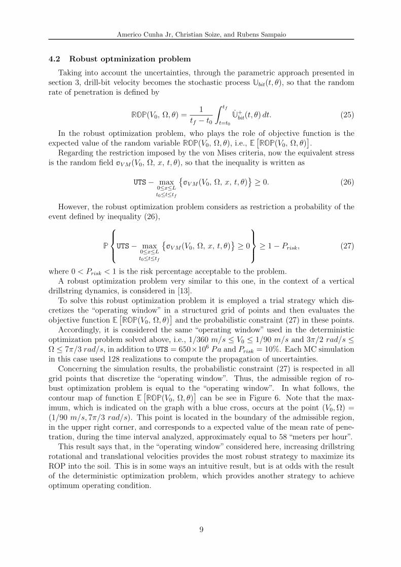
Concerning the simulation results, the probabilistic constraint (27) is respected in allgrid points that discretize the “operating window”. Thus, the admissible region of ro-bust optimization problem is equal to the “operating window”. In what follows, thecontour map of function E
[ROP(V0, Ω, θ)
]can be see in Figure 6. Note that the max-
imum, which is indicated on the graph with a blue cross, occurs at the point (V0,Ω) =(1/90 m/s, 7π/3 rad/s). This point is located in the boundary of the admissible region,in the upper right corner, and corresponds to a expected value of the mean rate of pene-tration, during the time interval analyzed, approximately equal to 58 “meters per hour”.
This result says that, in the “operating window” considered here, increasing drillstringrotational and translational velocities provides the most robust strategy to maximize itsROP into the soil. This is in some ways an intuitive result, but is at odds with the resultof the deterministic optimization problem, which provides another strategy to achieveoptimum operating condition.
9
Americo Cunha Jr, Christian Soize, and Rubens Sampaio
velocity (× 1/3600 m/s)
rota
tion
(× 2//
60 ra
d/s)
mean ROP (× 1/3600 m/s)
10 15 20 25 30 35 4045
50
55
60
65
70
20
25
30
35
40
45
50
55
Figure 6: Illustration of the contour plot of the mean rate of penetration function, for an “operatingwindow” defined by 1/360 m/s ≤ V0 ≤ 1/90 m/s and 3π/2 rad/s ≤ Ω ≤ 7π/3 rad/s. The maximum isindicated with a blue cross in the upper right corner.
5 CONCLUDING REMARKS
In this work a model that uses a beam theory, with effects of rotatory inertia and sheardeformation, which is capable of reproducing large displacements effects, is employed todescribe the nonlinear dynamics of horizontal drillstrings. This model also considers thefriction and shock effects due to transversal impacts, as well as, the force and torqueinduced by bit-rock interaction. The uncertainties of the bit-rock interaction model weretaken into account using a parametric probabilistic approach. A study aiming to max-imize drilling process efficiency, varying drillstring velocities of translation and rotationwas presented. The optimization strategy used a trial approach to seek for a local max-imum, which was located within “operating window” and corresponds to an efficiencyof approximately 16%. Two optimizations problems, one deterministic and one robust,where the objective was to maximize drillstring rate of penetration into the soil, respect-ing its structural limits, were formulated and solved. The solutions of these problemsprovided two different strategies to optimize the ROP.
ACKNOWLEDGEMENTS
The authors are indebted to Brazilian agencies CNPq, CAPES, and FAPERJ, andFrench agency COFECUB for the financial support given to this research. The firstauthor is grateful for the institutional support received from PUC-Rio and UniversiteParis-Est to carry out this work.
REFERENCES
[1] I. K. Chatjigeorgiou. Numerical simulation of the chaotic lateral vibrations of longrotating beams. Applied Mathematics and Computation, 219:5592–5612, 2013.
[2] S. J. Cull and R. W. Tucker. On the modelling of Coulomb friction. Journal ofPhysics A: Mathematical and General, 32:2103–2113, 1999.
10
Americo Cunha Jr, Christian Soize, and Rubens Sampaio
[3] A. Cunha Jr. Modeling and Uncertainty Quantification in the Nonlinear Stochas-tic Dynamics of a Horizontal Dsrillstrings. D.Sc. Thesis, Pontifıcia UniversidadeCatolica do Rio de Janeiro / Universite Paris-Est, 2015.
[4] A. Depouhon and E. Detournay. Instability regimes and self-excited vibrations indeep drilling systems. Journal of Sound and Vibration, 333:2019–2039, 2014.
[5] Y. Hu, Q. Di, W. Zhu, Z. Chen, and W. Wang. Dynamic characteristics analysis ofdrillstring in the ultra-deep well with spatial curved beam finite element. Journal ofPetroleum Science and Engineering, 82—83:166–173, 2012.
[6] T. J. R. Hughes. The Finite Element Method. Dover Publications, New York, 2000.
[7] K. H. Hunt and F. E. Crossley. Coefficient of restitution interpreted as damping invibroimpact. Journal of Applied Mechanics, 42:440–445, 1975.
[8] A. Cunha Jr, C. Soize, and R. Sampaio. Computational modeling of the nonlinearstochastic dynamics of horizontal drillstrings. (submitted for publication), 2015.
[9] Y. A. Khulief, F. A. Al-Sulaiman, and S. Bashmal. Vibration analysis of drillstringswith self-excited stick–slip oscillations. Journal of Sound and Vibration, 299:540–558,2007.
[10] X. Liu, N. Vlajic, X. Long, G. Meng, and B. Balachandran. Nonlinear motions ofa flexible rotor with a drill bit: stick-slip and delay effects. Nonlinear Dynamics,72:61–77, 2013.
[11] T. G. Ritto, M. R. Escalante, R. Sampaio, and M. B. Rosales. Drill-string horizontaldynamics with uncertainty on the frictional force. Journal of Sound and Vibration,332:145–153, 2013.
[12] T. G. Ritto, C. Soize, and R. Sampaio. Non-linear dynamics of a drill-string withuncertain model of the bit–rock interaction. International Journal of Non-LinearMechanics, 44:865–876, 2009.
[13] T. G. Ritto, C. Soize, and R. Sampaio. Robust optimization of the rate of penetra-tion of a drill-string using a stochastic nonlinear dynamical model. ComputationalMechanics, 45:415–427, 2010.
[14] S. M. Sahebkar, M. R. Ghazavi, S. E. Khadem, and M. H. Ghayesh. Nonlinearvibration analysis of an axially moving drillstring system with time dependent axialload and axial velocity in inclined well. Mechanism and Machine Theory, 46:743–760,2011.
[15] C. Soize. Stochastic Models of Uncertainties in Computational Mechanics. AmerSociety of Civil Engineers, Reston, 2012.
[16] C. Soize. Stochastic modeling of uncertainties in computational structural dynamics— recent theoretical advances. Journal of Sound and Vibration, 332:2379––2395,2013.


![FATIGUE OF DRILLSTRING: STATE OF THE ART€¦ · O Vaisberg et al. / Fatigue of Drillstring: State of the Art ... failure are the bases of the “API-RP-7G” [9] (API is the American](https://static.documents.pub/doc/80x56/5b83806c7f8b9a934f8d5cdc/fatigue-of-drillstring-state-of-the-art-o-vaisberg-et-al-fatigue-of-drillstring.jpg)


