Rock Mechanics and Ground control Table of Contents Chapter One: Basics of Rock Engineering.................3 Definition and Scope..................................3 Rock Measurements:....................................3 Rock Properties.......................................4 Chapter Two: Stress and Strain Analysis.................9 Rock Stress...........................................9 Virgin (in situ) Ground Stress.......................9 Vertical Stress......................................9 Horizontal Stress.....................................9 Residual Stress......................................9 Induced Ground Stress...............................10 Analysis of stress and state of stress...............11 Stress in two dimensions............................11 Stress notation and the components of stress on an oblique plane.......................................11 Analysis of strain...................................14 Deformation and state of strain in two dimensions...14 Hooke’s Law.........................................14 Strain energy.......................................16 Rockbursts..........................................17 Chapter Three: Stresses and Rock Behaviour Around Mining Excavations............................................ 20 Before Mining out....................................20 After Mining out.....................................20 Chapter Four: Mechanical Properties of Rock............23 The stress-strain curve..............................23 Fractures...........................................24 Definitions and concepts............................24 Behaviour of rock material in uniaxial compression. 25 Types of Fracture...................................26 Chapter Five: Rock Strength Determination..............27 Laboratory Testing...................................27 Field Tests..........................................28 UNIAXIAL COMPRESSION................................28 Strain Gauges for axial/radial strain?..............29 Point Load Testing..................................29 1
Transcript
Rock Mechanics and Ground control
Table of ContentsChapter One: Basics of Rock Engineering..............................................................3
Definition and Scope............................................................................................3Rock Measurements:............................................................................................3Rock Properties.....................................................................................................4
Chapter Two: Stress and Strain Analysis................................................................9Rock Stress.............................................................................................................9
Virgin (in situ) Ground Stress............................................................................9Vertical Stress......................................................................................................9
Analysis of stress and state of stress...........................................................11Stress in two dimensions..................................................................................11Stress notation and the components of stress on an oblique plane.........11
Analysis of strain................................................................................................14Deformation and state of strain in two dimensions......................................14Hooke’s Law.......................................................................................................14Strain energy......................................................................................................16Rockbursts..........................................................................................................17
Chapter Three: Stresses and Rock Behaviour Around Mining Excavations. . .20Before Mining out................................................................................................20After Mining out...................................................................................................20
Chapter Four: Mechanical Properties of Rock......................................................23The stress-strain curve......................................................................................23
Fractures.............................................................................................................24Definitions and concepts..................................................................................24Behaviour of rock material in uniaxial compression....................................25 Types of Fracture..............................................................................................26
Chapter Five: Rock Strength Determination.........................................................27Laboratory Testing..............................................................................................27Field Tests.............................................................................................................28
UNIAXIAL COMPRESSION............................................................................28Strain Gauges for axial/radial strain?.............................................................29Point Load Testing............................................................................................29BRAZIL Test.......................................................................................................30TRIAXIAL TESTING..........................................................................................31
Chapter Six: Rock Mass Classification Systems..................................................32Stability of Excavations.....................................................................................33Rock mass classification..................................................................................33
Terzaghi’s rock load classification..................................................................34Stini and Lauffer.................................................................................................35Rock structure rating.........................................................................................35Deere’s RQD......................................................................................................36
1
Rock Mechanics and Ground control
Geomechanics classification / RMR...............................................................37Mining Rock Mass Rating (MRMR)................................................................38Q Rating..............................................................................................................41
Chapter Seven: Support Systems..........................................................................42Passive Support Systems.................................................................................42Active Support Systems....................................................................................42Types of Support.................................................................................................42
Pillar Systems......................................................................................................55Classification of pillars......................................................................................55Backfill.................................................................................................................56
Chapter Eight: Mining Methods and Support Type Relationships.....................59Pillar design criteria............................................................................................59
Tributory theory..................................................................................................60Factors affecting Pillar strength.......................................................................61Factor of safety (FS).........................................................................................61
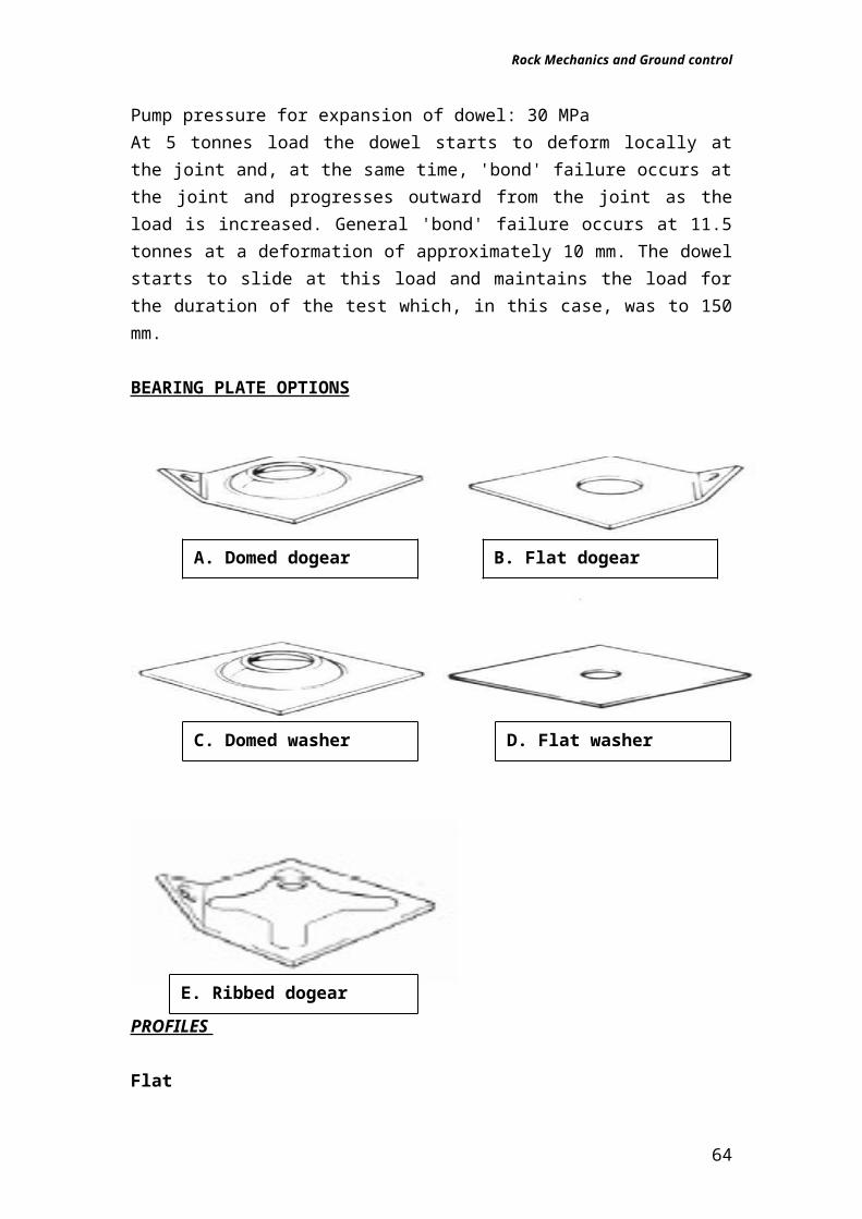
Mining Practise....................................................................................................63Chapter Nine: Special Blasting Techniques..........................................................65
Smooth Blasting..................................................................................................66Chapter Ten: Instrumentation and Monitoring......................................................67
Monitoring systems............................................................................................67Modes of operation............................................................................................68
Chapter Twelve: Mining Induced Subsidence......................................................69Types and effects of mining induced subsidence.....................................69Continuous or Trough subsidence:...............................................................70Discontinuous Subsidence:.............................................................................70
Design measures to limit subsidence.............................................................71
2
Rock Mechanics and Ground control
Chapter One:Basics of Rock Engineering
Definition and ScopeRock mechanics is the theoretical and applied science of the mechanical behavior of Rock. It is that branch of mechanics concerned with the response of rock to the force fields of its physical environment. It is convenient to subdivide rock mechanics into the following branches:a) Structural rock mechanics, which is concerned with the stability of engineering structures in which the material is predominantly rock.b) Comminution, which is concerned with the reduction of rock to small fragments by the application of external forces as in drilling, blasting, cutting and grinding.Both these branches of rock mechanics involve the control of rock deformation and fracture processes. In the first case, excessive rock failure (in this context, failure is taken to mean either excessive deformation or fracture) must be avoided in order to preserve the stability of the structure and, in the second case, rock fracture must be induced with the minimum input of external energy. Thus, knowing and understanding basic rock properties will allow structures to be founded correctly so the required support will be there.
Rock Measurements:
The physical characteristics of a rock mass are a fundamental geologic property and are extremely important to engineers. Analytical data on theses characteristics are generally derived in 2 ways:
1. Laboratory measures: are generally referred to as 'rock properties' and are acquired using small samples taken from the field site and analyzed in a laboratory setting. The range of Lab Tests is as follows:
Uniaxial Compressive Strength (UCS) Triaxial strength test Tensile strength test (Brazil test) Density & moisture content Shear strength test on discontinuities Various index tests
2. Field-scale measures: most often referred to as 'rock mass properties' and are descriptions of the bulk strength properties of the rock mass. The nature of these properties are governed primarily by 'discontinuities', or planes of weakness, that are present in the rock mass. Examples of discontinuities are fractures, bedding planes, faults, etc. The measured distance between
3
Rock Mechanics and Ground control
fractures, bedding planes, and other structural features are also important when collecting field-scale data. Field Tests involve subjecting a large volume of rock to load & monitoring the deformation. The following is observed:
More representative results The volume of rock still not big enough? More expensive Test location/development changes?
Rock Properties
Not all rock is the same and it must be treated differently in an engineering project. There are 3 fundamental processes which form rock which are igneous, metamorphic, and sedimentary processes. Each of these basic rock types have inherent structural characteristics that define it strength and durability, and hence, its usefulness in an engineering situation. It is very important to assess some basic properties of rock. Some of the more important properties of rocks are:
A. Specific Gravity: this term describes the weight of a volume of rock with respect to an equal volume of water, which weighs 1.0 gm/cm3. By weighing equal volumes of water and different rocks, a 'specific gravity' (SG) for that rock can be determined. These experiments are conducted in a controlled laboratory using very specific guidelines so there are no unexpected variations. After such work has been performed, typical SG's for common rock types are:
B. Mass Density: this is derived by multiplying the specific gravity by the density of water, specified as 1000 kg/m3. So, for the above examples, the mass densities would be:
Shale: 2.75 x 1000 kg/m3 = 2750 kg/m3
Granite: 2.65 x 1000 kg/m3 = 2650 kg/m3
Sandstone: 2.2 x 1000 kg/m3 = 2200 kg/m3
Basalt: 2.65 x 1000 kg/m3 = 2650 kg/m3
Marble: 2.7 x 1000 kg/m3 = 2700 kg/m3
Gold: 14 x 1000 kg/m3 = 14,000 kg/m3
C. Rock Strength: is a measure of the strength of a rock mass when subjected to any one or a combination of three primary forces:
4
Rock Mechanics and Ground control
1. Compressive Stress: this stress consists of two opposing forces acting on a rock which decreases the volume of the rock per unit area.
'Compressive strength' is the maximum force that can be applied to a rock sample without breaking it. Units of stress are either reported in pounds per square inch (Psi in English units) or Newtons per square meter (N/m2 in metric units). 1.0 Newton is equal to 1.0 Kg-m/s2 and is derived by multiplying the mass by the gravity force, 9.81m/s2.
Using this method, the force on the bottom of a 1.0 m3 block of granite due to gravity is:
2.65 x 1000 kg/m3 = 2600 kg (this is the mass of the block)We know that F = ma, so F = (2600 kg) x (9.81 m/s2) = 2.55 x 10⁴ kg-m/s2, or 2.55 x 10⁴ N
This resulting force is acting on the total area at the bottom of the block, which is 1.0 m2, so the total force exerted by the 1.0 m3 block of granite is 2.55 x 10⁴
N/m2.
Metric units of stress are equal to Pascals (Pa), which are units of pressure. The equality is: 1.0 N/m2 = 1.0 Pa. Compressive strength is derived by dividing the force over the area upon which it acts and is specified as the Greek letter σ. The stress formula is given as:
σ = P/A where P is the engineering way of expressing force, F.
For example, we wish to determine the compressive force on a 6.0 m3 (1m wide, 1m deep, 6m high) block of granite that has an applied load (force) of 2000 KN. Does this load exceed the compressive strength for granite?
Solution: Using the above formula, we find the stress on the block as force divided by area:
5
Forces acting toward one another will decrease the volume
Rock Mechanics and Ground control
σ = P/A = 2,000,000 N / 1.0 m2 = 2,000,000 N/m2 which is well below the compressive strength of granite which ranges upward from about 200 x 106
N/m2.
NOTE: Compressive strength generally decreases as d increases especially for coarse grained & fissured rocks strength of a core decreases as length, l, increases and also the more flaws the greater chance of unfavourable orientation of flaws?
2. Tensile Strength: rocks placed in tension will show a decrease in the total volume of the rock per unit area due to forces directed outward, opposite in action.
Tensile strength for a rock is usually much lower than its compressive strength, i.e., rocks are most likely to fail under tension well before they would fail under compression. Thus, it is very important to know the stress regime a rock will be subjected to when used in an engineering project. Most rock materials are never placed in a situation where tension is the primary force.
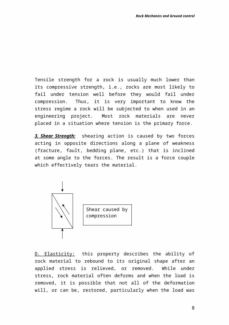
3. Shear Strength: shearing action is caused by two forces acting in opposite directions along a plane of weakness (fracture, fault, bedding plane, etc.) that is inclined at some angle to the forces. The result is a force couple which effectively tears the material.
6
Shear caused by compression
Forces acting outward from the rock body will decrease the volume as the material stretches. Failure from tension occurs at a much lower value than from compression
Rock Mechanics and Ground control
D. Elasticity: this property describes the ability of rock material to rebound to its original shape after an applied stress is relieved, or removed. While under stress, rock material often deforms and when the load is removed, it is possible that not all of the deformation will, or can be, restored, particularly when the load was excessively heavy. There are 2 ranges used to describe deformation of the rock:
1. Elastic deformation: occurs when all of the deformation caused by the stress is restored upon its release.
2. Plastic deformation: when stress that is below a critical threshold value is released, all of the deformation is restored. However, if the applied stress exceeds the threshold value (which differs for various materials and rock types), permanent deformation results due to the load. This means that when the load is removed, there is a permanent alteration to the original shape of the rock or material. This may, or may not, be a critical concern in an engineering project.
E. Strain: is a property that is somewhat related to elasticity. Materials that are subjected to a load, whether it be compressive, tensile, or shear, will deform and either stretch or shrink in length. This action is referred to as 'strain' and is described mathematically as:
ε = ΔL , where L is length and ΔL is the change in length. L
This is a dimensionless number. It is a length divided by a length which is dimensionless.
F) 'Modulus of Elasticity The ratio between stress and strain is referred to as the 'Modulus of Elasticity', or Young's Modulus and is denoted as E. Mathematically:
E=P/A = σ ΔL/L Є
The last rock strength parameter we will explore is a property that describes the amount of lateral extension (strain) of a material that is under a vertical (axial) strain:
Lateralstrain=ΔB/Baxial strain ΔL/L
where B is in terms of lateral dimensions. This ratio is designated ν, or 'Poisson's ratio'. ν varies in natural rock from between 0.1 to 0.5.
7
Rock Mechanics and Ground control
One example of the use of Poisson's ratio is in the analysis of the propagation of an energy wave generated by an earthquake. This wave moves through solid rock and is, therefore, somewhat subjected to rock properties. The speed of propagation, or wave velocity, is dependent upon the Poisson's ratio of the rock. As rock type changes, wave velocity changes as a function of rock properties.
Chapter Two:Stress and Strain Analysis
Rock StressA force field that is applied to a liquid or gas is called a pressure; if applied to a solid it is termed a state of stress. The pressure at a point in a liquid or gas is always equal or uniform in each direction (i.e. it is hydrostatic), but the stress will in general vary, depending on the direction. The stress state at a point in a rock mass is a tensor quantity – the magnitude of the stress and the nature of the stress depends on the direction of interest. It is important to distinguish between virgin stress (existing before mining), the induced stress (the stress change induced in the rock by the action of mining), and the field stress or total stress (the sum of the virgin and the induced stress fields).Virgin (in situ) Ground StressThe natural stress that exists in a rock mass before it is subjected to mining is referred to as a “virgin,” “primitive,” or “in situ” stress. For purposes of analysis, the vertical and horizontal components are considered separately. The vertical stress component is simply calculated by elastic analysis for any particular depth of proposed mining, while the horizontal stress is not.Vertical StressIn the rocks of the world, the vertical stress is typically a straight-line function of the weight of the column of rock lying above the depth in question. The following formula is true for typical quartz and feldspar rich hard rocks with a SG of 2.65.Average vertical stress gradient = 2.65/102 = 0.0260 MPa/m of depth, orIn rock mechanics this vertical stress may be referred to as the “gravitational stress,” “lithological stress,” or “overburden stress.”Horizontal StressDetermining the natural horizontal stress is more difficult. The horizontal stress is usually larger thanpredicted by simple elastic analysis, and it is not equal in each direction. Furthermore, horizontal stress is site specific. Generally, it is considered that the horizontal stress is a maximum in one direction and decreases to a minimum in the direction orientated at 90 degrees. The maximum is referred to in the literature as the “principal” or “major” stress (σ1), and its orientation as the “major axis.” The minimum, normal (90 degrees) to the maximum, is
8
Rock Mechanics and Ground control
typically referred to as the “intermediate” stress, (σ2), since the “minor” stress, (σ3) is usually vertical.Residual StressThe intensity and orientation of virgin stress may be significantly altered when the mine is situated near a major fault line in the earth’s crust. This type of virgin stress is classed as one sort of tectonic stress. If the cause of a tectonic stress is later relieved by force of nature, a portion of the stress remains in the rock and is referred to as residual stress.Industry NotesThe following notes (accredited to experts) are selected and arranged in a sequence designed facilitate understanding of the horizontal stress phenomenon. The notes start with general observations, then discuss a large regional district (Canadian Shield), and finally refer to a specific mining location within the district.
By elastic theory, the horizontal stress ought to be near one-third the vertical stress. In fact, it is always much higher than this. In the absence of in situ stress measurements or other indications of a higher horizontal stress, the most reasonable
assumption (for open pit slope analysis) is that the horizontal stress is equal to the vertical stress. Source: Richard Call
High horizontal stresses are a worldwide phenomenon. At a depth of 1,500 feet (450m) in the earth’s crust, horizontal stresses exceed the vertical stress.
Induced Ground Stress Two separate classifications of induced ground stress exist. The first is static, similar to virgin ground stress in that it is relatively stationary. The second is dynamic and moves through the rock mass at the speed of sound. Dynamic stress is normally referred to as a seismic stress.Static StressWhen the miner excavates an opening underground, the stresses in the rock surrounding the void increase due to the fact that he has put a hole in the virgin stress field. The increase is called an “induced” stress. The induced stress is best demonstrated by considering the case of a vertical shaft in a uniform horizontal stress field. By elastic analysis, the circumpherential stress at the skin of the shaft wall is double the horizontal ground stress that existedbefore the shaft was sunk, and then decreases with depth into the wall rock. The magnitude of the additional induced stress (Qi) at the skin and any distance into the wall rock may be calculated by simple elastic analysis with the Spalding formula.Qi = Q[r2/(r + y)2]Q is the original virgin ground stress, r is the radius of the shaft, and y is the distance into the wall rock (at the skin, y =0, therefore, Qi = Q).
9
Rock Mechanics and Ground control
This theory is close to the truth if the shaft is round and perfectly smooth (i.e. a drilled shaft), regardless of the shaft diameter. It is also virtually true for a shaft pilot hole that was diamond drilled, even though its diameter is many times smaller than the shaft. Additionally, the theory is the case for the blastholes in the shaft bottom, whether drilled by a plugger or jumbo. In hard rock, the magnitude of this stress at the skin of the shaft wall is actually closer to zero if the shaft is conventionally drilled and blasted. In this case, the horizontal stress is only increased by about 50%, and this maximum increase in stress is found at some distance into the wall rock (i.e. in the shaft pillar). The distance to this maximum stress depends on and is roughly proportional to the shaft diameter.
Seismic StressAn event such as a round being shot or a fault slip produces a seismic response that is a sudden alteration in pressure, stress, particle displacement, and particle velocity, propagated in waves through an elastic medium. In rock mechanics, the rock mass is the medium, and it is often possible to hear a seismic wave as a noise, similar to a hammer blow or blast.
ANALYSIS OF STRESS AND STATE OF STRESS
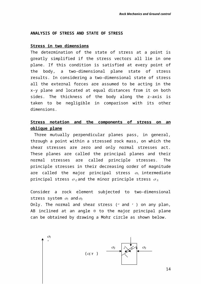
Stress in two dimensionsThe determination of the state of stress at a point is greatly simplified if the stress vectors all lie in one plane. If this condition is satisfied at every point of the body, a two-dimensional plane state of stress results. In considering a two-dimensional state of stress all the external forces are assumed to be acting in the x-y plane and located at equal distances from it on both sides. The thickness of the body along the z-axis is taken to be negligible in comparison with its other dimensions.
Stress notation and the components of stress on an oblique plane Three mutually perpendicular planes pass, in general, through a point within a stressed rock mass, on which the shear stresses are zero and only normal stresses act. These planes are called the principal planes and their normal stresses are called principle stresses. The principle stresses in their decreasing order of magnitude are called the major principal stress 1,
intermediate principal stress 2, and the minor principle stress 3.
Consider a rock element subjected to two-dimensional stress system 1 and 3
10
Rock Mechanics and Ground control
Only. The normal and shear stress ( and ) on any plan, AB inclined at an angle to the major principal plane can be obtained by drawing a Mohr circle as shown below.
1
3 B 3
(,, ) A
Q
1
P 2 (3,o) , (1,o)
(1 +3)/2
from point P on the circle called the pole or the origin of the plane AB on which the stress is required. The intersection point gives the stresses and whose values may be written as:
= ½(1 + 3) +½ (1-3) cos2 1 = ½ (1-3) sin2 2 The point P (pole) on the circle is a unique point useful to find the stresses on any plane, which should be drawn from this point to intersect the circle. If the stresses ( and ) on a plane are known, the stresses are marked on the circle and a line is drawn from this stress point parallel to the plane. The line will intersect the circle at the pole.It can be shown that the magnitude of the principal forces can be calculated from the equations1 =½(x + y) +½ [(x-y)2 +4 xy
2] 32 =½(x + y) -½ [(x-y)2 +4 xy
2] 4and the angle can be gotten fromtan2=2 xy/(x-y)solving this equation for we get the following equation=½arctan[2 xy/(x-y)]+ k90 5where k= 0,1,2,3
11
Rock Mechanics and Ground control
Example For the following given state of stress find the magnitude and directions of the principal forces x = -2,5 kPa y= 12,5 kPa, xy= -13,0 kPaSolnUsing equations 3 and 4 the magnitude of 1 and
To determine the direction of the principal stresses one can calculate 1 and 2 from equation 5=½arctan[2 xy/(x-y)]=½arctan[2(-13,0) /(-2,5 - 12,5)]Because both the numerator and denominator are negative in the last term, trigonometrical considerations indicate that 180 21 2701=½*240.022 =30.1
ExampleA 25mm diameter rock bolt of high tensile strength 700Mpa will breakwhen the ultimate load (Pc) induces a critical value of stress c which is equal to the strength of the bolt. Calculate Pc.
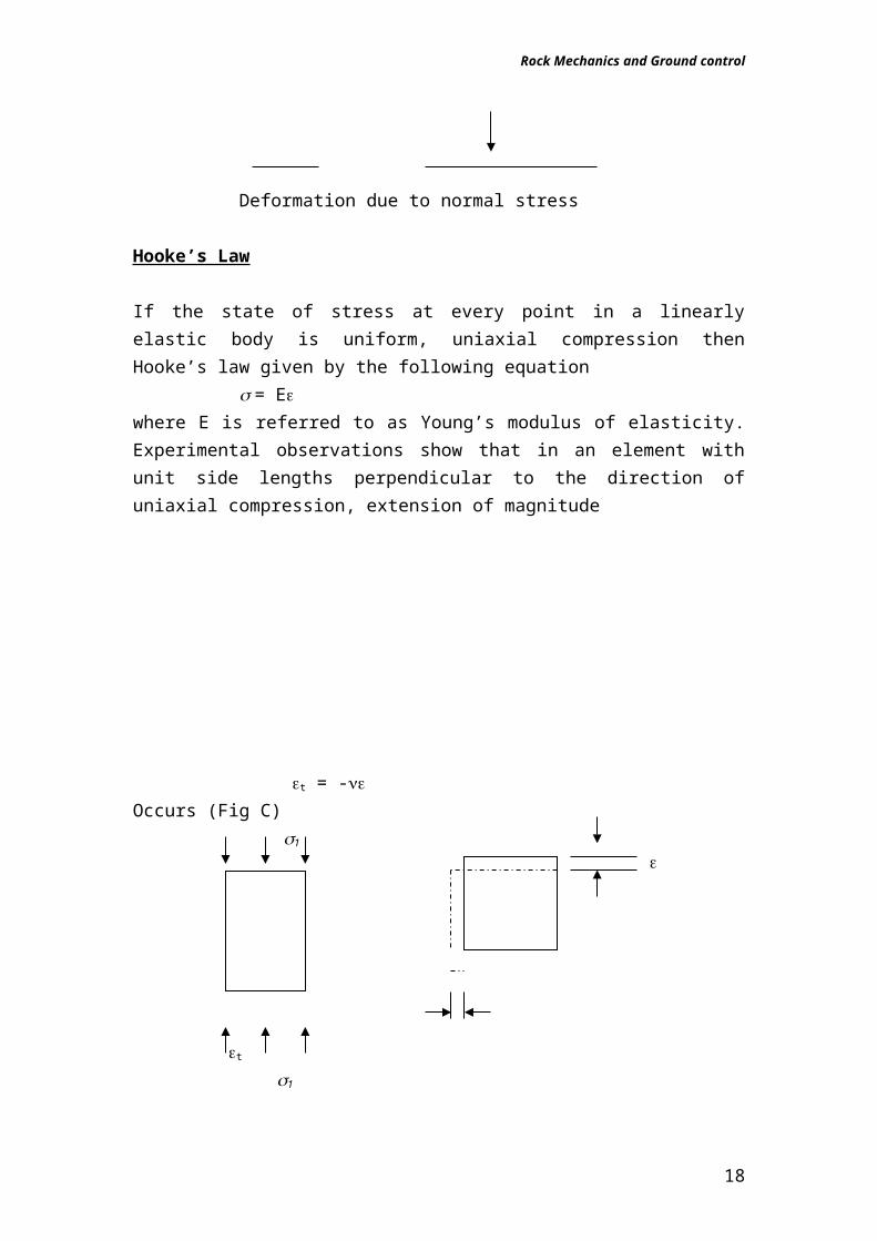
Considering the following simple loading conditions shown below. If a compressive stress, , acts on a cylindrical specimen of a material its original length l will decrease to a smaller length. Denoting the new length of the specimen by l, the change in the specimen length is usually expressed in terms of the original length. This may be written as:= (l -l)/ l is, therefore the deformation of unit length of the material in the direction of the applied normal stress. is referred to as normal strain and taken to be positive when it signifies shortening, compressive strain , and negative when it signifies lengthening, tensile strain.
l l
Deformation due to normal stress
Hooke’s Law
If the state of stress at every point in a linearly elastic body is uniform, uniaxial compression then Hooke’s law given by the following equation
= E where E is referred to as Young’s modulus of elasticity. Experimental observations show that in an element with unit side lengths perpendicular to the direction of uniaxial compression, extension of magnitude
t = -
13
Rock Mechanics and Ground control
Occurs (Fig C)1
t 1
in the equation below, the constant , determined from the ratiot =
is known as Poison’s ratio.Modulus of rigidity is given byG = E 2(1+)where G is referred to as the modulus of rigidity.
State of plane strain
The appropriate relations between the normal components of stress and strain, for the state of plain can be derived from the condition that z = 0, and given as z = (x + y) x = 1(1- 2) x - (1+ 2) y
E z = 1(1- 2) y - (1+ 2) x
E
1 = E (1+2) (1-2)
2 = E (1-2) (1-2)
tan 2 = xy
x- y
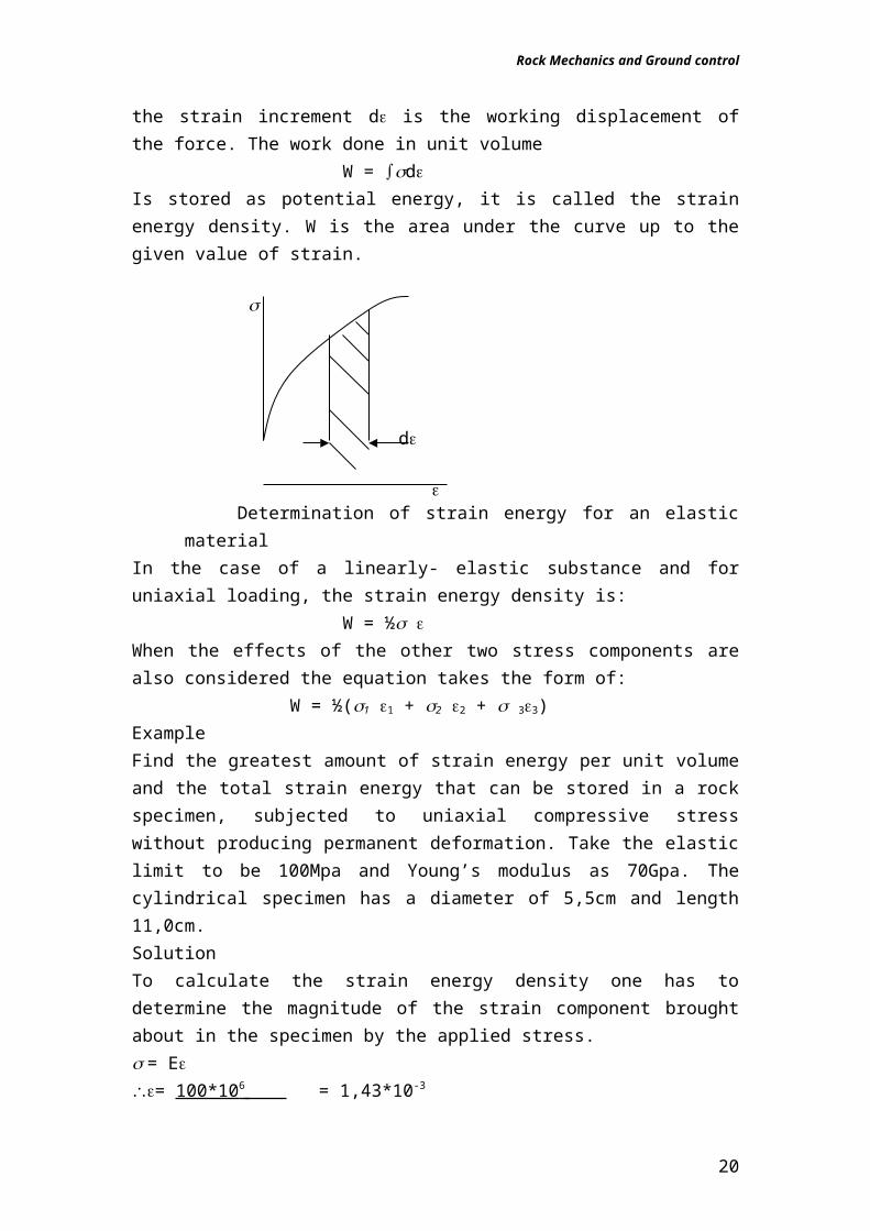
Strain energyWhen stresses act on an element of an elastic body and deform it, the work done by the stresses is stored within the body in the form of strain energy. To quantify this energy, consider a unit cube of the material for which the stress
14
Rock Mechanics and Ground control
is the force on one of the faces. Similarly, the strain increment d is the working displacement of the force. The work done in unit volume
W = dIs stored as potential energy, it is called the strain energy density. W is the area under the curve up to the given value of strain.
d
Determination of strain energy for an elastic material
In the case of a linearly- elastic substance and for uniaxial loading, the strain energy density is:
W = ½ When the effects of the other two stress components are also considered the equation takes the form of:
W = ½(1 1 + 2 2 + 33)ExampleFind the greatest amount of strain energy per unit volume and the total strain energy that can be stored in a rock specimen, subjected to uniaxial compressive stress without producing permanent deformation. Take the elastic limit to be 100Mpa and Young’s modulus as 70Gpa. The cylindrical specimen has a diameter of 5,5cm and length 11,0cm.SolutionTo calculate the strain energy density one has to determine the magnitude of the strain component brought about in the specimen by the applied stress. = E= 100*10 6 = 1,43*10-3
70*109
then, the strain energy density is:W = ½ W = ½*(100*106)* (1,43*10-3) = 71,50 kJ/m3 since both the stress and strain components are constant throughout the specimen, the total strain energy is determined by the product of the volume of the specimen and the strain energy density.Q = 0,055 2 * 011* 71.50*103 = 0.02kJ 4
15
Rock Mechanics and Ground control
RockburstsRockbursts are sudden, damage-causing movements that may occur in highly stressed rock. Rockbursts commonly occur on a small scale (“face bursts” or “air blasts”) where small particles of brittle wall rock “spit” from the face. Less frequently, but more dangerously, slabs of rock can be blown from the wall rock. Occasionally, a larger volume of rock such as a rock pillar can fail suddenly, or a fault or other large discontinuity can slip. This can cause widespread damage in what is termed a majorseismic event. Major failures can be terribly harmful sometimes resulting in multiple fatalities and mine closures. Today the term “rockburst” is commonly defined as a seismic event resulting in more than 5 tonnes of rock coming down in an underground opening Causes of RockburstsRock StiffnessRockbursts are believed to be caused by high-ground stress in hard rock. Hard rock is described in literature as “crystalline,” “clastic,” or “elastic” rock [as opposed to “plastic” rock that tends to squeeze (creep) rather than burst when stressed to the yield point]. Hard rock may be described as being brittle or “stiff.” The measure of stiffness is Young’s modulus of elasticity, E.Elastic Instability When a significant portion of the whole structure fails instantly and catastrophically, the term used is “general instability.” General instability failure is characterized by abrupt and violent collapse accompanied by instantaneous release of energy, one component of which is a loud noise resembling a thunderclap. The stress at which failure occurs is not predictable, only the minimum stress level at which it can occur can be determined and used as a criteria for safe Rock Type Basalt Dolomite Granite Limestone Sandstone Schist
Combating Rockbursts ScreenJust as insulation on wiring will not protect it from a lightning strike, typical ground support (rock bolts, shotcrete, timber, or concrete) is not effective by itself to prevent rockbursts or major seismic events. Screen is valuable because it can contain flying rock from air blasts. The screen is more effective when covered with shotcrete.ProceduresSeveral procedures are now employed to deal with rockbursts The first is simply to wait for ground to stabilize after a blast before allowing man entry to an advancing stope face or heading.The second is to design stope blasts to induce a rockburst simultaneously with the explosion, thus restoring ground stability.The third is to induce complete failure of a pillar around a heading or a support pillar in a stope, thus rendering it incapable of carrying high loads.
16
Rock Mechanics and Ground control
Tutorials1. Given x =20Mpa and y =0Mpa, xy =-40MPa. Find the principal
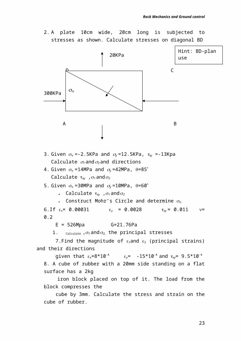
stresses and their directions.2. A plate 10cm wide, 20cm long is subjected to stresses as shown.
Calculate stresses on diagonal BD
20KPa
D C
300KPa
A B
3. Given x =-2.5KPa and y =12.5KPa, xy =-13KpaCalculate 1 and 2 and directions
4. Given x =14MPa and y =42MPa, =85 Calculate xy ,1 and 2
5. Given x =30MPa and y =10MPa, =60 Calculate xy ,1 and 2
Construct Mohr’s Circle and determine n
6.If x= 0.00031 y = 0.0028 xy = 0.011 = 0.2 E = 526Mpa G=21.76Pa
i. Calculate ,1 and 2, the principal stresses
7.Find the magnitude of 1and 2 (principal strains) and their directions given that x=8*10-4 y= -15*10-4 and xy= 9.5*10-4
8. A cube of rubber with a 20mm side standing on a flat surface has a 2kg iron block placed on top of it. The load from the block compresses the cube by 3mm. Calculate the stress and strain on the cube of rubber.9. A plane has an area of 20cm2 and across this plane a force of 50KN acts, which has a direction of action being inclined at 72 degrees to the normal to the plane.
Calculate Normal stress to the plane Maximum shear stress across the plane
10. A cube of dense iron with a specific gravity of 3t/m is at a depth of200m below surface.
17
n
Hint: BD-plan use n normal to
Rock Mechanics and Ground control
Given poisons ratio is 0.3. Calculate the strain energy(NB all the strain energy is in the form of potential energy)
A rockburst occurs at that depth below surface and a 1m3 cube of iron ore is released at 4.5m/s. Calculate the new strain energy in the released cube.
If poisson’s ratio remains unchanged and given the following data E = 70Gpa xy= 20Mpa L x = 0.2m Ly=0.1m. Calculate the principal stresses and their components
11.A rockburst occurs at a depth of 2500m below surface and 1m3 of the rock attains a velocity of 4.3m/s
Chapter Three:Stresses and Rock Behaviour Around Mining Excavations
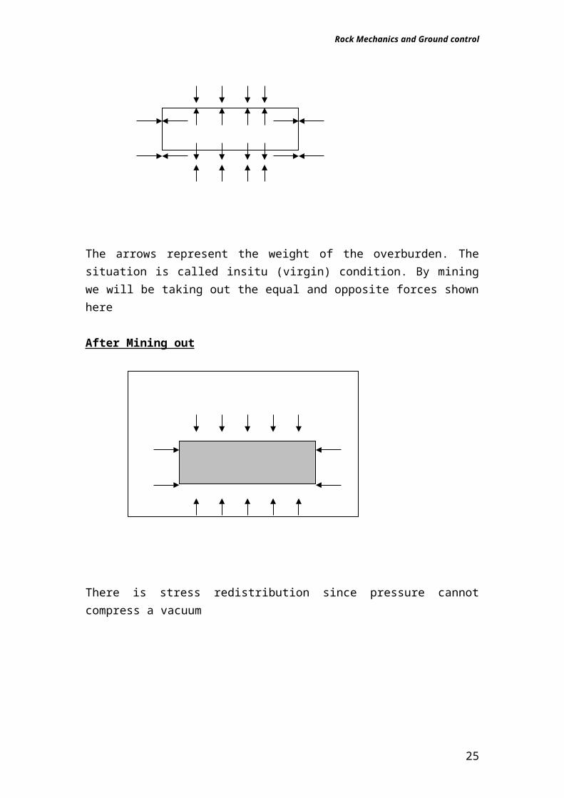
Before Mining out
The arrows represent the weight of the overburden. The situation is called insitu (virgin) condition. By mining we will be taking out the equal and opposite forces shown here
After Mining out
18
Rock Mechanics and Ground control
There is stress redistribution since pressure cannot compress a vacuum
When stoping starts, a slot is taken out of the rock. The weight of the rock above the slot cannot be transmitted through the air space in the slot and has to be supported by the solid rock on either side of the slot, i.e. at the stope face. This increased load will cause additional stress in the rock on either side of the slot. This additional stress, not including the primitive or virgin stress, is called induced stress. In an underground excavation stress is redistributed adjacent to the opening and will be concentrated close to the opening then reduces further into the rock. The fig above shows an illustration of the distribution of stress.
19
Rock Mechanics and Ground control
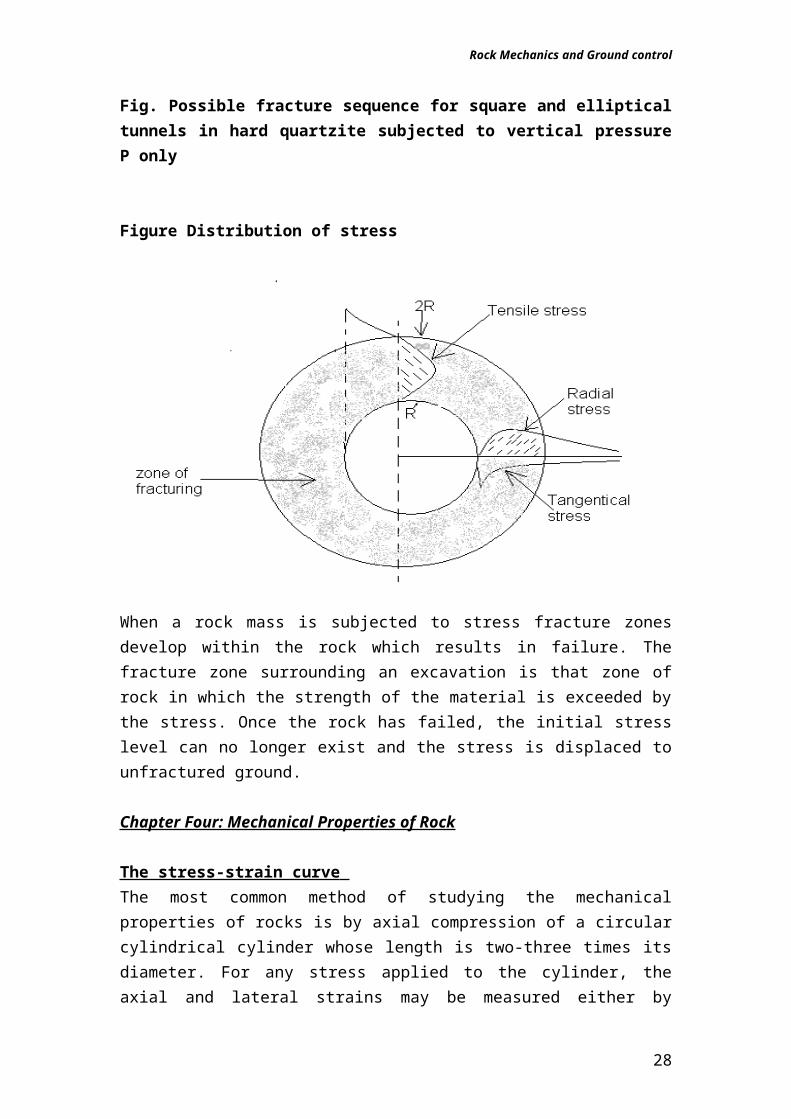
Fig. Possible fracture sequence for square and elliptical tunnels in hard quartzite subjected to vertical pressure P only
20
a) Formation of vertical and floor cracks P>3700
a) Formation of vertical and floor cracks P>3000
b) Sidewall failure originating in square corners at P>7500
b) Sidewall failure in the form of scaling occurs at P>13000
c) Stress redistribution due to roof and floor and sidewall fractures may induce extension of existing cracks and also initiate fracture remote from original boundary
c) Stress redistribution due to roof and floor and sidewall fractures may induce further sidewall scaling and also initiate fracture remote from original boundary
d) Possible final fracture configuration
d) Possible final fracture configuration
Rock Mechanics and Ground control
Figure Distribution of stress
When a rock mass is subjected to stress fracture zones develop within the rock which results in failure. The fracture zone surrounding an excavation is that zone of rock in which the strength of the material is exceeded by the stress. Once the rock has failed, the initial stress level can no longer exist and the stress is displaced to unfractured ground.
Chapter Four: Mechanical Properties of Rock
The stress-strain curve The most common method of studying the mechanical properties of rocks is by axial compression of a circular cylindrical cylinder whose length is two-three times its diameter. For any stress applied to the cylinder, the axial and lateral strains may be measured either by strain gauges attached to the cylinder or by measurement of displacements. If stress is plotted against strain a stress-strain curve is obtained.
F
F
0 0
21
Rock Mechanics and Ground control
a) Linearly elastic material b) elastic material
0 0 c) Plastic-elastic material d) Plastic-elastic-plastic material
for most rocks the stress-strain curve takes the linear form of figure(a) ending abruptly at F. this may be represented as =E
Where the constant E is called Young’s Modulus C
B
D
A
0 The complete stress-strain curve for rocksRegion BehaviourOA Nearly Elastic but loading and
unloading in this region does not produce irreversible changes in structure
AB Nearly Elastic but loading and unloading in this region does not produce irreversible changes in structure
BC Linearly Elastic, in this region irreversible changes to the rock are induced, and successive cycles of loading and unloading trace out
22
Rock Mechanics and Ground control
different curves.CD This region begins at the maximum
point and is characterised by a negative slope of the stress-strain curve. This region is characteristic of brittle material( this is when its ability to resist load decreases with increasing deformation)
Fractures
Definitions and concepts Fracture : it is the formation of planes of separation in the rock material.
It involves the breaking of bonds to form new surfaces. The onset of failure is normally associated with failure or the attainment of peak strength.
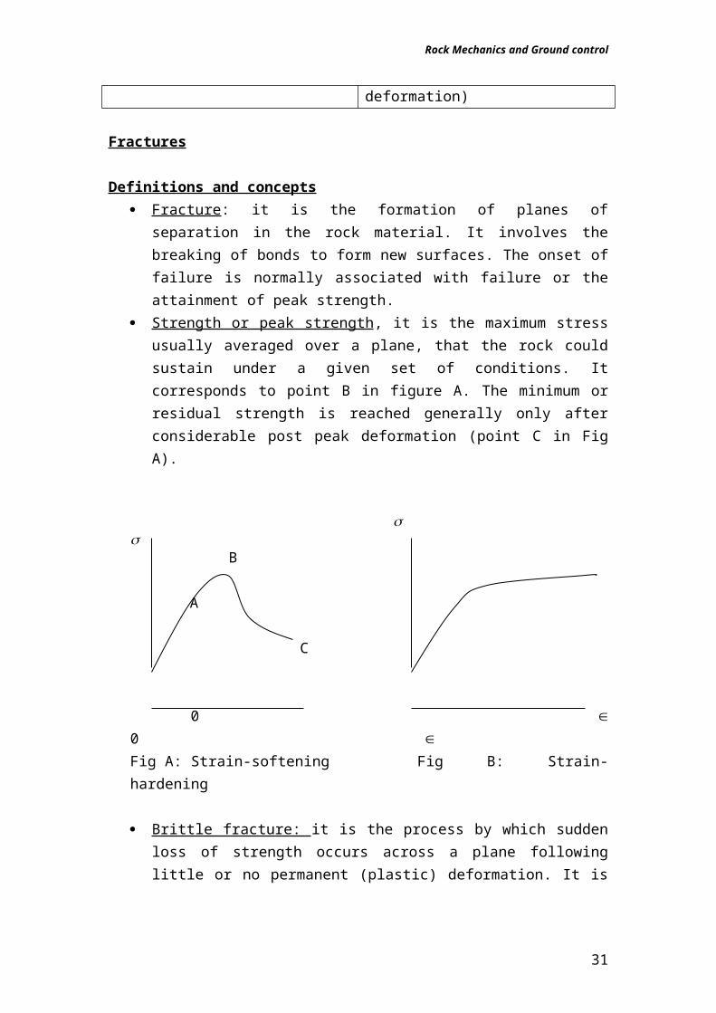
Strength or peak strength , it is the maximum stress usually averaged over a plane, that the rock could sustain under a given set of conditions. It corresponds to point B in figure A. The minimum or residual strength is reached generally only after considerable post peak deformation (point C in Fig A).
Brittle fracture: it is the process by which sudden loss of strength occurs across a plane following little or no permanent (plastic) deformation. It is associated with strain-softening or strain-weakening behaviour as illustrated in Fig A.
Ductile deformation: occurs when the rock can sustain further permanent deformation without losing load-carrying capacity (Fig B).
Yield: occurs when there is a departure from elastic behaviour i.e. when some of the deformation becomes irrecoverable as at A in Fig A.
23
Rock Mechanics and Ground control
Behaviour of rock material in uniaxial compression
Influence of rock type and condition: for similar mineralogy c
(uniaxial compressive strength) will decrease with increasing porosity, increasing degree of weathering, increasing degree of microfissuring and increasing water content. Thus for example the uniaxial compressive strength of sandstone will vary according with grain size, the packing density, the nature and extent of cementing between the grains and the levels of pressure and temperature that the rock has been subjected to throughout its history.
Influence of specimens volume: c will decrease with increasing specimen volume due to surface energy.
Influence of strain rate: the rate at which you apply strain especially if you do it very fast or very slow will result in different stress-strain behaviour being observed.
Influence of testing machine stiffness: the Fig below illustrates the interaction between a specimen and a conventional testing machine. The machine is represented by a linear elastic spring and the by a non- inear spring.
Machine (linear) P Specimen (non-linear)
Hence if the machine is stiff it will have an effect on the results of the test.
Types of Fracture In all discussions of brittle fracture the nature and description of the fractured surface is of the greatest importance.
A) B) C) D) E)
A) Longitudinal splitting in uniaxial compression: in axial compression in Fig A irregular longitudinal splitting is observed
24
Rock Mechanics and Ground control
B) Shear fracture : with quite a moderate amount of confining pressure the irregular behaviour of A is replaced by a single plane of fracture.
C) Multiple shear fractures: if the confining pressure is increased so that the material becomes fully ductile, a network of shear fractures accompanied by plastic deformation of the individual crystals appears.
D) Extension fracture: this appears typically in uniaxial tension. It is characterised by a clean separation with no offset between the surfaces.
E) Extension fracture produced by line loads: if a slab is compressed between line loads, the extension fracture appears between the loads.
Coulumb CriterionIt is the simplest and most important criterion. It suggests that in connection with shear failures of rocks that the shear stress tending to cause failure across a plane is resisted by the cohesion (adherence) of the material and by a constant times the normal stress. That is II = So + Where and are the normal and shear stresses across the plane, So is a constant of which may be regarded as the inherent shear strength of the material, and is the coefficient of internal friction of the material. Although it is widely used, Coulumb’s criterion is not particularly satisfactory peak strength criterion for rock material. The reasons for this are:
a) It implies shear fracture exists at peak strength but observations show this is not always the case.
b) It implies a direction of shear failure that does not always agree with experimental observations.
Griffith Crack TheoryGriffith postulated a theory that fracture of brittle materials, such as steel and glass, is initiated at tensile stress concentrations at the tips of minute, thin cracks (now referred to as Griffith cracks) distributed throughout an otherwise isotropic, elastic material. Griffith's theory of brittle fracture3, modified to allow for the predominantly compressive stresses in rock mechanics, has been found to provide a reliable theoretical basis for the prediction of rock fracture phenomena5. This theory is based upon the assumption that fracture initiates at inherent cracks and discontinuities within the material and that propagation of these cracks occurs as a result of the tensile stress which is induced at the crack tip under load. Brace6 has shown that fracture in hard rock usually initiates in grain boundaries which can be regarded as the inherent discontinuities required by the Griffith theory. Griffith's original theory was concerned with brittle fracture under conditions of applied tensile stress and he based his calculations upon the assumption that the inherent crack, from which fracture initiates, could be treated as an elliptical opening. When applied to rock mechanics, in which the applied stresses are predominantly
25
Rock Mechanics and Ground control
compressive, this simplifying assumption is no longer valid and the theory has to be modified to account for the frictional forces which occur when the crack faces are forced into contact. Chapter Five: Rock Strength Determination
Laboratory Testing UCS Triaxial Point load Index Brazil test Schmidt hammer Degradation testing
Field Tests
Involve subjecting a large volume of rock to load & monitoring the deformation
More representative results The volume of rock still not big enough? More expensive Test location/development changes?
LAB TESTS
On discontinuities and cores of intact rock. Empirical models can then provide an estimate of the rock mass characteristics. Below is the range of Lab Tests used in rock mechanics these days
Uniaxial Compressive Strength (UCS) Triaxial strength test Tensile strength test (Brazil test) Density & moisture content Shear strength test on discontinuities Various index tests
We will now look at some of these tests
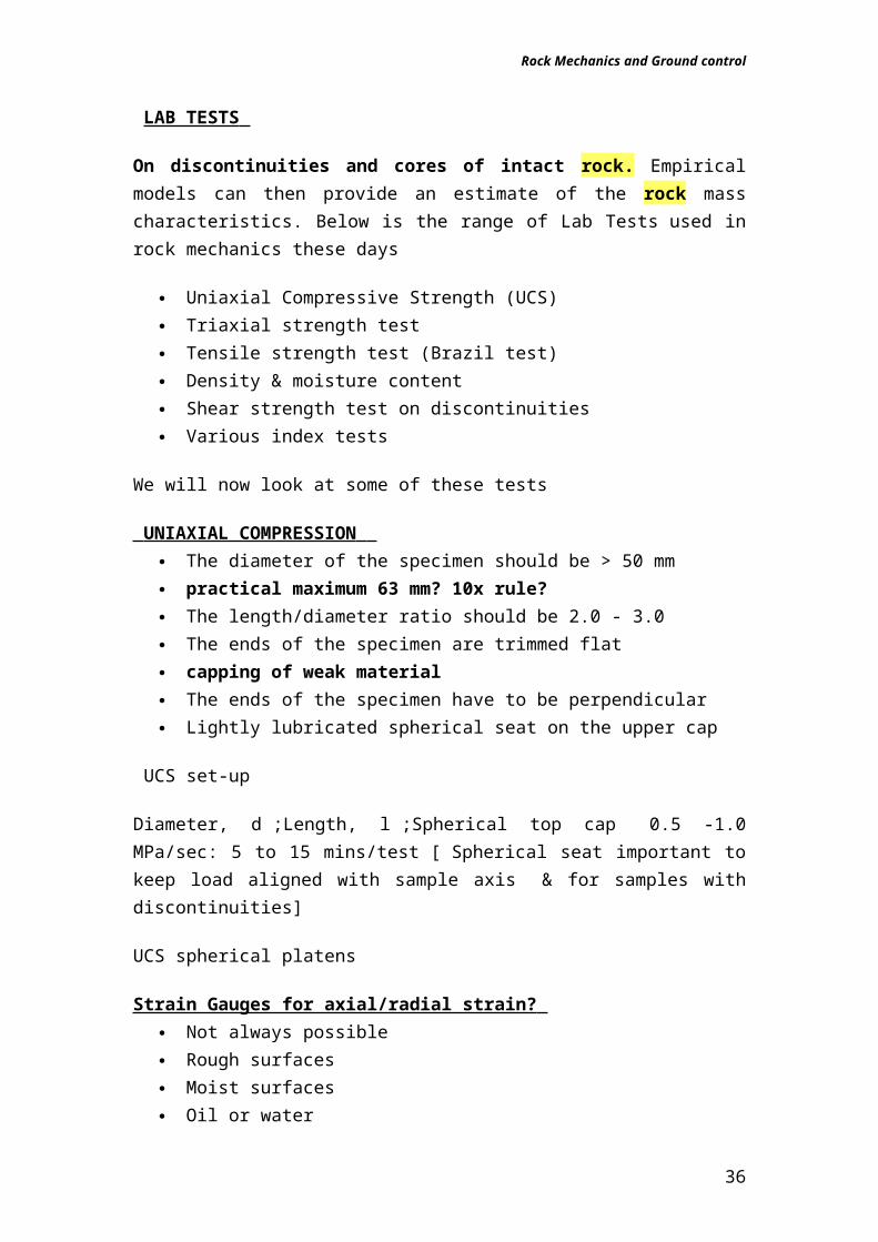
UNIAXIAL COMPRESSION The diameter of the specimen should be > 50 mm practical maximum 63 mm? 10x rule? The length/diameter ratio should be 2.0 - 3.0 The ends of the specimen are trimmed flat capping of weak material
26
Rock Mechanics and Ground control
The ends of the specimen have to be perpendicular Lightly lubricated spherical seat on the upper cap
UCS set-up
Diameter, d ;Length, l ;Spherical top cap 0.5 -1.0 MPa/sec: 5 to 15 mins/test [ Spherical seat important to keep load aligned with sample axis & for samples with discontinuities]
UCS spherical platens
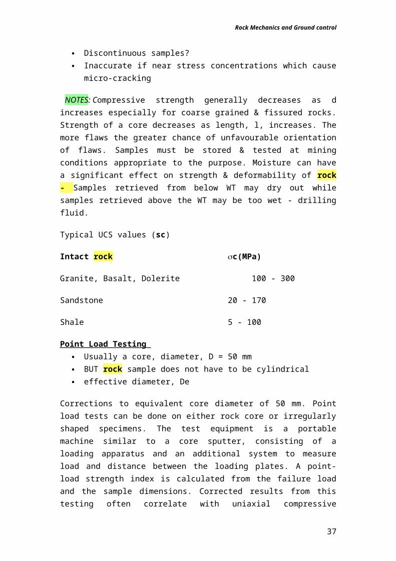
Strain Gauges for axial/radial strain? Not always possible Rough surfaces Moist surfaces Oil or water Discontinuous samples? Inaccurate if near stress concentrations which cause micro-cracking
NOTES: Compressive strength generally decreases as d increases especially for coarse grained & fissured rocks. Strength of a core decreases as length, l, increases. The more flaws the greater chance of unfavourable orientation of flaws. Samples must be stored & tested at mining conditions appropriate to the purpose. Moisture can have a significant effect on strength & deformability of rock - Samples retrieved from below WT may dry out while samples retrieved above the WT may be too wet - drilling fluid.
Typical UCS values (sc)
Intact rock c(MPa)
Granite, Basalt, Dolerite 100 - 300
Sandstone 20 - 170
Shale 5 - 100
Point Load Testing Usually a core, diameter, D = 50 mm BUT rock sample does not have to be cylindrical effective diameter, De
Corrections to equivalent core diameter of 50 mm. Point load tests can be done on either rock core or irregularly shaped specimens. The test equipment is a portable machine similar to a core sputter, consisting of a loading
27
Rock Mechanics and Ground control
apparatus and an additional system to measure load and distance between the loading plates. A point-load strength index is calculated from the failure load and the sample dimensions. Corrected results from this testing often correlate with uniaxial compressive strength of rock substance. It is a simple, reliable, and inexpensive means to measure substance strength and the results are useful for rock classification purposes.
Schmidt Hammer
Same as used for concrete Rebound on standard impact converted to f’c = c Take many samplings to get a statistical mean
BRAZIL Test
Of the two most common tests for determining tensile strength, indirect tension (Brazilian) and direct tension, the Brazilian test is the least expensive, easiest, and most commonly used. A Brazilian test consists of diametrically loading a disk of rock core until it fails. Theoretically, the diametrical loading induces a tensile stress in the center of the disk, and failure occurs parallel to the direction of loading. The direct tension test pulls a cylindrical rock sample at both ends until the specimen fails.
28
Rock Mechanics and Ground control
TRIAXIAL TESTING
Apparatus: Spherical top cap, Strain gauged specimen, axial and radial strain, Stiff rubber jacket, Solid steel cell and Oil instead of water to provide 3 . the values in Mpa. You need to apply 1 through ram as oil loaded .
29
Square section neoprene ring for adjustment of clearance gap
Clearance Gap
Hydraullic pressure P
Rock specimen
Latex rubber sleeve
Fig: Apparatus for determining the tensile strength of rock specimen
3 = P(d22 - d 1
2 ) d1
2
1= 2 = P
Rock Mechanics and Ground control
Chapter Six: Rock Mass Classification Systems
Introduction
During the feasibility and preliminary design stages of a project, when very little detailed information on the rock mass and its stress and hydrologic
30
Hardened and ground steel spherical seats
Clearance gap for gauge wires
Mild steel cell body
Rock specimen with ground ends and with a length to diameter ratio of 2
Oil inlet – maximum pressure 700MPa
Strain gauges – if required
Rubber sealing sleeve
Figure: Cut – away view of a triaxial cell for testing rock specimens
Rock Mechanics and Ground control
characteristics is available, the use of a rock mass classification scheme can be of considerable benefit. At its simplest, this may involve using the classification scheme as a check-list to ensure that all relevant information has been considered. At the other end of the spectrum, one or more rock mass classification schemes can be used to build up a picture of the composition and characteristics of a rock mass to provide initial estimates of support requirements, and to provide estimates of the strength and deformation properties of the rock mass. It is important to understand that the use of a rock mass classification scheme does not (and cannot) replace some of the more elaborate design procedures. However, the use of these design procedures requires access to relatively detailed information on in situstresses, rock mass properties and planned excavation sequence, none of which may be available at an early stage in the project. As this information becomes available, the use of the rock mass classification schemes should be updated and used in conjunction with site specific analyses.
Stability of ExcavationsThe application of rock mechanics (along with the advent of remote control mucking) has enabled the introduction of open stoping to ore bodies that were previously only mined by tedious cut-and-fill methods. This has been accomplished by increasing the hanging wall span that can be exposed in an open stope while controlling the increased tendency for dilution.This important evolution has enabled greater mechanization and made economic recovery possible from ore zones that might otherwise have been abandoned.The requirement for large spans has been met with an empirical analysis of structural stability that is dependent upon rock classification systems.RQD, Rock Mass Rating (RMR), and Quality (Q) are the three classification systems used today in the mining industry evolved from systems first developed for civil engineering works, particularly tunnels.
Rock mass classification
A rock mass is generally weaker and more deformable than its constituent rock material as the mass contains structural weakness planes such as joints and faults. The stability of an excavation in a jointed rock mass is influenced by many factors including:
strength of rock material frequency of jointing
31
Rock Mechanics and Ground control
joint strength confining stress Presence of water.The best practical way in which these weakening/strengthening effects can be taken into account is by applying rock mass classification methods.
Quantitative classification of rock masses has become almost routine, since it provides a rapid means of quantifying the quality of a mass, comparing quality, and assessing support requirements. Classification applied on a routine basis can have tremendous value in mines.
Terzaghi’s rock load classification
Estimates loads to be supported by steel aches and is based upon experience in steel support in the Alps. Ranges of rock loads are assigned for various ground conditions. Rock conditions are classified as intact rock, stratified rock, moderately jointed rock, blocky and seamy rock, crushed rock, squeezing rock and swelling rock.
Intact rock is that rock that contains neither joints nor hair cracks. Hence, if it breaks, it breaks across sound rock. On account of the injury to the rock due to blasting, spalls may drop off the roof several hours or days after blasting. This is known as a spalling condition. Hard, intact rock may also be encountered in the popping condition involving the spontaneous and violent detachment of rock slabs from the sides or roof.
Stratified rock consists of individual strata with little or no resistance against separation along the boundaries between the strata. The strata may or may not be weakened by transverse joints. In such rock the spalling condition is quite common.
Moderately jointed rock contains joints and hair cracks, but the blocks between joints are locally grown together or so intimately interlocked that vertical walls do not require lateral support. In rocks of this type, both spalling and popping conditions may be encountered.
Blocky and seamy rock consists of chemically intact or almost intact rock fragments which are entirely separated from each other and imperfectly interlocked. In such rock, vertical walls may require lateral support.
Crushed but chemically intact rock has the character of crusher run. If most or all of the fragments are as small as fine sand grains and no recementation has taken place, crushed rock below the water table exhibits the properties of water-bearing sand.
Squeezing rock slowly advances into the tunnel without perceptible volume increase. A prerequisite for squeeze is a high percentage of
32
Rock Mechanics and Ground control
microscopic and sub-microscopic particles of micaceous minerals or clay minerals with a low swelling capacity.
Swelling rock advances into the tunnel chiefly on account of expansion. The capacity to swell seems to be limited to those rocks that contain clay minerals such as montmorillonite, with a high swelling capacity.
Stini and Lauffer
This system correlates rock types, active span (unsupported) of rock and stand up time. In a tunnel, the unsupported span is defined as the span of the tunnel or the distance between the face and the nearest support, if this is greater than the tunnel span. Lauffer's original classification has since been modified by a number of authors, notably Pacher et al (1974), and now forms part of the general tunneling approach known as the New Austrian Tunneling Method. The significance of the stand-up time concept is that an increase in the span of the tunnel leads to a significant reduction in the time available for the installation of support. For example, a small pilot tunnel may be successfully constructed with minimal support, while a larger span tunnel in the same rock mass may not be stable without the immediate installation of substantial support. The New Austrian Tunneling Method includes a number of techniques for safe tunneling in rock conditions in which the stand-up time is limited before failure occurs.These techniques include the use of smaller headings and benching or the use of multiple drifts to form a reinforced ring inside which the bulk of the tunnel can be excavated. These techniques are applicable in soft rocks such as shales, phyllites and mudstones in which the squeezing and swelling problems, described by Terzaghi, are likely to occur. The techniques are also applicable when tunneling in excessively broken rock, but great care should be taken in attempting to apply these techniques to excavations in hard rocks in which different failure mechanisms occur. In designing support for hard rock excavations it is prudent to assume that the stability of the rock mass surrounding the excavation is not time-dependent. Hence, if a structurally defined wedge is exposed in the roof of an excavation, it will fall as soon as the rock supporting it is removed. This can occur at the time of the blast or during the subsequent scaling operation. If it is required to keep such a wedge in place, or to enhance the margin of safety, it is essential that the support be installed as early as possible, preferably before the rock supporting the full wedge is removed. On the other hand, in a highly stressed rock, failure will generally be induced by some change in the stress field surrounding the excavation. The failure may occur gradually and manifest itself as spalling or slabbing or it may occur suddenly in the form of a rock burst. In either case, the support design must take into account the change in the stress field rather than the ‘stand-up’ time of the excavation.
33
Rock Mechanics and Ground control
Rock structure rating
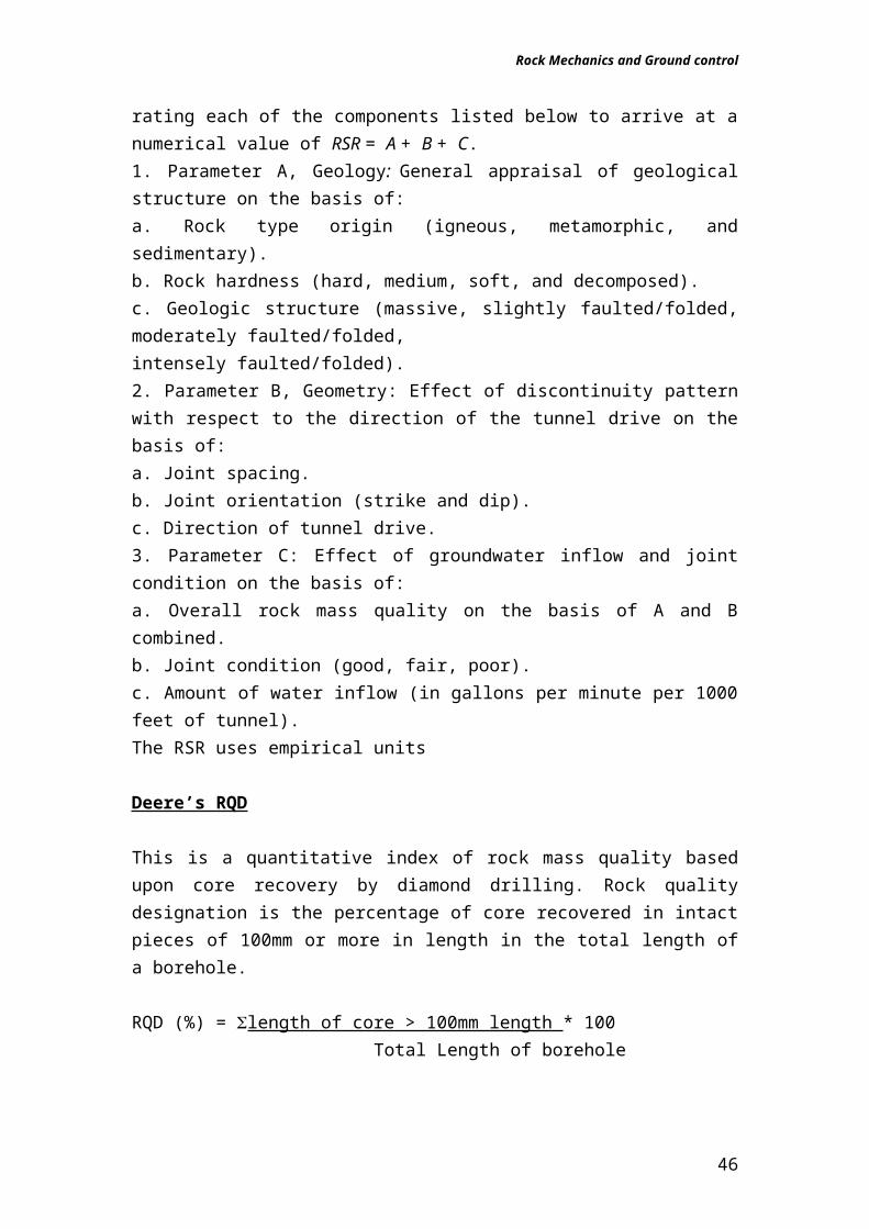
Wickham et al (1972) described a quantitative method for describing the quality of a rock mass and for selecting appropriate support on the basis of their Rock Structure Rating (RSR) classification. Most of the case histories, used in the development of this system were for relatively small tunnels supported by means of steel sets, although historically this system was the first to make reference to shotcrete support. In spite of this limitation, it is worth examining the RSR system in some detail since it demonstrates the logic involved in developing a quasi-quantitative rock mass classification system. The significance of the RSR system, in the context of this discussion, is that it introduced the concept of rating each of the components listed below to arrive at a numerical value of RSR = A + B + C.1. Parameter A, Geology: General appraisal of geological structure on the basis of:a. Rock type origin (igneous, metamorphic, and sedimentary).b. Rock hardness (hard, medium, soft, and decomposed).c. Geologic structure (massive, slightly faulted/folded, moderately faulted/folded,intensely faulted/folded).2. Parameter B, Geometry: Effect of discontinuity pattern with respect to the direction of the tunnel drive on the basis of:a. Joint spacing.b. Joint orientation (strike and dip).c. Direction of tunnel drive.3. Parameter C: Effect of groundwater inflow and joint condition on the basis of:a. Overall rock mass quality on the basis of A and B combined.b. Joint condition (good, fair, poor).c. Amount of water inflow (in gallons per minute per 1000 feet of tunnel).The RSR uses empirical units
Deere’s RQD
This is a quantitative index of rock mass quality based upon core recovery by diamond drilling. Rock quality designation is the percentage of core recovered in intact pieces of 100mm or more in length in the total length of a borehole.
RQD (%) = length of core > 100mm length * 100 Total Length of borehole
34
Rock Mechanics and Ground control
Example
Palmström (1982) suggested that, when no core is available but discontinuity traces are visible in surface exposures or exploration adits, the RQD may be estimated from the number of discontinuities per unit volume. The suggested relationship for clay-free rock masses is:RQD = 115 - 3.3 Jv (4.1)Where Jv is the sum of the number of joints per unit length for all joint (discontinuity) sets known as the volumetric joint count. RQD is a directionally dependent parameter and its value may change significantly, depending upon the borehole orientation. The use of the volumetric joint count can be quite useful in reducing this directional dependence. RQD is intended to represent the rock mass quality in situ. When using diamond drill core, care must be taken to ensure that fractures, which have been caused by handling or the drilling process, are identified and ignored when determining the value of RQD. When using Palmström's relationship for exposure mapping, blast induced fractures should not be included when estimating Jv. Deere's RQD has been widely used, particularly in North America, for the past 25 years. Cording and Deere (1972), Merritt (1972) and Deere and Deere (1988) have attempted to relate RQD to Terzaghi's rock load factors and to rock bolt requirements
35
Total length of core run = 200cmRQD (%) = length of core > 100mm length * 100
Total Length of borehole
RQD = 38 + 17 + 20 + 35 * 100 = 55%200
L =38 cm
L = 17 cm
L = 0No pieces 10 cm
L = 20 cm
L = 35 cm
L = 0No recovery
Rock Mechanics and Ground control
Geomechanics classification / RMR
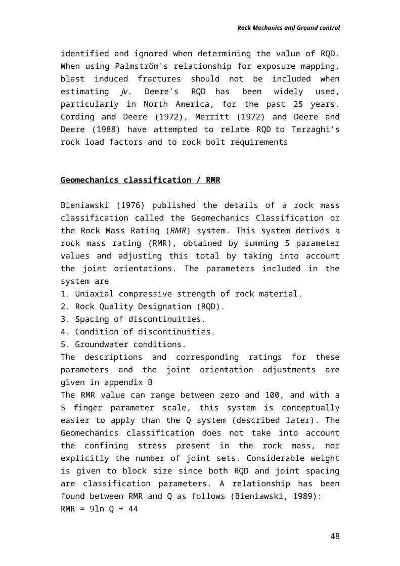
Bieniawski (1976) published the details of a rock mass classification called the Geomechanics Classification or the Rock Mass Rating (RMR) system. This system derives a rock mass rating (RMR), obtained by summing 5 parameter values and adjusting this total by taking into account the joint orientations. The parameters included in the system are1. Uniaxial compressive strength of rock material.2. Rock Quality Designation (RQD).3. Spacing of discontinuities.4. Condition of discontinuities.5. Groundwater conditions.The descriptions and corresponding ratings for these parameters and the joint orientation adjustments are given in appendix BThe RMR value can range between zero and 100, and with a 5 finger parameter scale, this system is conceptually easier to apply than the Q system (described later). The Geomechanics classification does not take into account the confining stress present in the rock mass, nor explicitly the number of joint sets. Considerable weight is given to block size since both RQD and joint spacing are classification parameters. A relationship has been found between RMR and Q as follows (Bieniawski, 1989):RMR = 9ln Q + 44Over the years, this system has been successively refined as more case records have been examined and it should be noted that Bieniawski has made significant changes in the ratings assigned to different parameters. In applying this classification system, the rock mass is divided into a number of structural regions and each region is classified separately. The boundaries of the structural regions usually coincide with a major structural feature such as a fault or with a change in rock type. In some cases, significant changes in discontinuity spacing or characteristics, within the same rock type, may necessitate the division of the rock mass into a number of small structural regions.
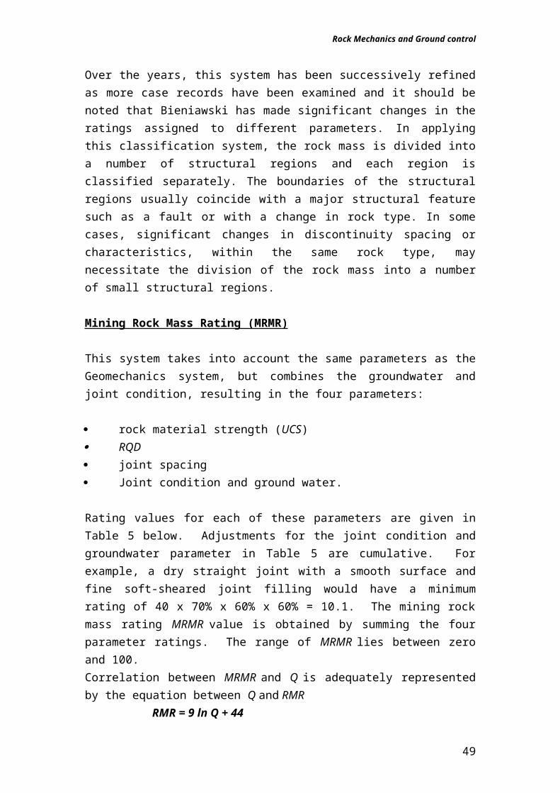
Mining Rock Mass Rating (MRMR)
This system takes into account the same parameters as the Geomechanics system, but combines the groundwater and joint condition, resulting in the four parameters:
rock material strength (UCS) RQD joint spacing Joint condition and ground water.
36
Rock Mechanics and Ground control
Rating values for each of these parameters are given in Table 5 below. Adjustments for the joint condition and groundwater parameter in Table 5 are cumulative. For example, a dry straight joint with a smooth surface and fine soft-sheared joint filling would have a minimum rating of 40 x 70% x 60% x 60% = 10.1. The mining rock mass rating MRMR value is obtained by summing the four parameter ratings. The range of MRMR lies between zero and 100.Correlation between MRMR and Q is adequately represented by the equation between Q and RMR
RMR = 9 ln Q + 44The mining rock mass classification is better suited to real stability assessment since it is also concerned with cavability.
Table Mining Rock Mass RatingParameter Range of Values
1
RQD 100-97 96-84 83-71 70-56 55-44 43-3130-17
16-4 3-0
Rating( = RQD x 15/100)
15 14 12 10 8 6 4 2 0
2UCS (MPa) 185
184-165
184-165
164-145
144-125
124-105
104-85
84-65
44-25
24-5
4-0
Rating 20 18 16 14 12 10 8 6 4 2 0
3
Joint Spacing
Rating 25 0
4
Joint ConditionIncluding Groundwater
Rating 40 0
Adjustments are applied to the MRMR value to take account of weathering of the rock mass, joint orientation relative to the excavation, mining-induced stresses and blasting effects.
Modified stability number N
37
Rock Mechanics and Ground control
This system is a modification of the Q System. The parameter SRF (The Stress Factor) is not used, and three specific multiplying factors are applied to take particular account of rock strength to stress effect, joint orientation, and gravity. Initially Q¢ is calculated as in the Q System as:
Q¢ = RQD/Jn x J r /Ja x Jw
Dry conditions are experienced in most underground hard rock environments and Q¢ then reverts to:
Q¢ = RQD/Jn x Jr /Ja
The modified stability number N¢ is calculated as:N¢ = Q¢ x A x B x C
Where:
A is a factor which allows for the strength to stress effect. A is given by:
A = 1.125R – 0.125 1>A>0.1
WhereR is the ratio of the Uniaxial compressive strength of the rock material to the maximum induced compressive stress. The latter is determined by stress analyses.B is a factor which allows for the ease of block fall out effect. B is given by the following equations:
Where a is the true angle between the "hanging" surface of the excavation and the joint plane. In the case of several joint planes, the smallest angle is applicable. The true angle can be determined using a stereo net.
C is the gravity adjustment factor. In the case of gravity falls and slabbing, in which no sliding on joints is involved, the factor is given by the following equation:
C = 8 – 6 x cos (dip of stope face)When sliding on joints is involved, the gravity adjustment factor is given by the following equations:
C = 8 Dip of critical joint < 30o
38
Rock Mechanics and Ground control
C = 11 – 0.1 x Dip of critical joint Dip of critical joint > 30Brady, B.H.G. and Brown, E.T. 1985. Rock mechanics for underground mining. London: Allen and Unwin.
Q Rating
The Q System classification is based on three aspects:
rock block size (RQD/Jn) joint shear strength ( Jr /Ja) confining stress (Jw/SRF)Where: RQD is the rock quality designation
Jn is the joint set numberJr is the joint roughness numberJa is the joint alteration numberJw is the joint water reduction factorSRF is the stress reduction factor.
RQD = 115 — (3.3 x Jt)
Where Jt is the total number of joints per cubic meter i.e. Jt = Jh + Jd + JsNotes: Where RQD is reported or measured as less than 10, a nominal value of
10 is used to evaluate Q. RQD intervals of 5, giving 100, 95, 90 … 10 are sufficiently accurate. Jn - Joint Set Number A numerical value is allocated, corresponding with the number of joint sets
present in the rock mass.Calculation of Q
All selected values for the above six parameters, based on observed or estimated conditions are substituted into the equation to obtain the value of the rock quality index
The Q system does not take the rock material strength into account explicitly, although it is implicitly included in arriving at the SRF assessment. The orientation of joints is also not taken into account since it is considered that the number of joint sets, and hence the potential freedom of movement for rock blocks is more important.
39
Rock Mechanics and Ground control
The range in values of Q is from 0.001 for extremely poor rock to 1000 for excellent rock. Barton, N., Løset, F., Lien, R. and Lunde, J. 1980. Application of the Q-system in design decisions.
Chapter Seven: Support Systems
Passive Support Systems
Any support which is installed unstressed can be regarded as being passive. Such support only begins to function only in response to rock movement (passive support is not installed with an applied loading, but rather, develops its load as the rock mass deforms). Because the movement of unfractured rock is usually small, passive support only becomes effective once the rock falls around the excavations. This delayed build up of support resistance often results in a deterioration of mining conditions, which could be prevented by using supports, which are either rapid bearing or active. Passive support may be provided by steel arches, timbered sets, composite stacks, untensioned grouted rock bolts, reinforcing bars or cables
Active Support Systems
A support structure is active if the exerts and maintains a restraint on the rock immediately after installation. The essential feature of an active support system is that the provision of the initial support force does not depend on rock movement. Typical examples of active support structures are hydraulic props and rock bolts. Both types of support can be preloaded by external installation tools.
Types of Support
Timber supportThe classic support element is the ordinary timber prop, which is still being used widely in productive excavations either as temporary or permanent. Timber props have a number of advantages; the most important of these are their lightness and high support resistance at high initial stiffness. Another is they give audible warning when they are being overloaded. Probably the greatest disadvantage of timber props is its comparative lack of yield properties. The use of this type is, therefore restricted to that of temporary face support or in case of permanent support to mining situations where the irresistible rock mass movement is small.
Timber packsA number of situations arise in mining in which the yield properties of timber props are insufficient. Unlike timber props packs are constructed from a
40
Rock Mechanics and Ground control
number of elements, which can have either identical or different properties. The initial load bearing capacity of a support pack can be improved greatly by incorporating into the pack members of high individual stiffness. The most common approach is to replace some of the timber members by concrete bricks. Two different types of timber-concrete packs are the sandwich and composite packs.
Concrete support
The limited yield properties of concrete severely restrict its application as a support material in tabular excavations. The use of solid concrete pillars is restricted to the support of shallow tabular excavations with competent hanging wall strata. A recent development to counter this is the addition of fibrous materials to the concrete to improve its yield properties and to change the mode of failure from that of brittle material to one of a more ductile material.
Steel support
Because of its excellent mechanical properties steel is used widely as a support material in productive excavations. The two best-known applications are as rock or roof bolts and props.
Rock bolts or studs
The steel used to manufacture rock bolts is either mild steel grade 4.6 or high tensile steel grade 6.6. The bolts are anchored at the end of the drill holes by either an expansion shell or by cement grout or resin. In production ends were support, which can be applied quickly, is often required, expansion shell type bolts or resin bonded bolts are normally used. The choice between the two types of anchorage is governed by the quality of the rock in the immediate hanging wall. In case of the competent rock, expansion shell anchors are often preferred as they are easy to install and act immediately.
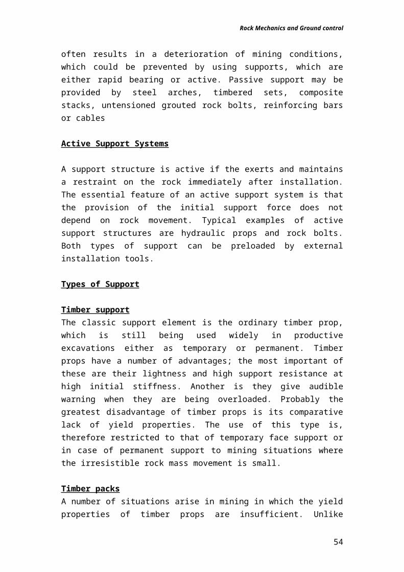
Split-set:
This is a yielding rock bolt. This is a split tube manufactured of spring steel which is hammered into the borehole of a slightly smaller diameter that the split-set. The compressed steel ring exerts radial pressure in the borehole, which grip the split-set to the rock. Apart from its yielding properties the main advantages of the split-set are its simplicity and ease of installation. A serious disadvantage is the dependence of the support function on the borehole diameter.
41
Rock Mechanics and Ground control
Swellex' dowels
Developed and marketed by Atlas Copco, the 'Swellex' system is illustrated in Figure Below. The dowel, which may be up to 12 m long, consists of a 42 mm diameter tube which is folded during manufacture to create a 25 to 28 mm diameter unit which can be inserted into a 32 to 39 mm diameter hole. No pushing force is required during insertion and the dowel is activated by injection of high pressure water (approximately 30 MPa or 4,300 psi) which inflates the folded tube into intimate contact with the walls of the borehole. Corrosion of Swellex dowels is a matter of concern since the outer surface of the tube is in direct contact with the rock. Speed of installation is the principal advantage of the Swellex system as compared with conventional rockbolts and cement grouted dowels. In fact, the total installation cost of Swellex dowels or Spilt Set stabilisers tends to be less than that of alternativereinforcement systems, when installation time is taken into account. Both systems are ideal for use with automated rockbolters.
42
Fig: Split set stabiliser. Ingersol - Rand
Rock Mechanics and Ground control
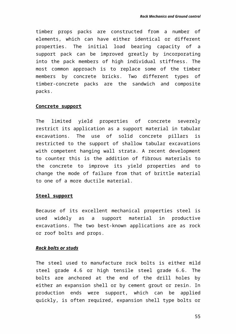
Rock bolt with an extension shell anchor, tensioned and grouted
43
25 to 28mm diameter folded tube
Expanded dowel
33 to 39mm diameter hole
Fig: Atlas Copco Swellex dowel
Cone
Bail
Shell
Tape
Breather tube
Grout Injection tube
Faceplate drilled for tubes
Fig: Components of a mechanically anchored rockbolt with provision for grouting
Rock Mechanics and Ground control
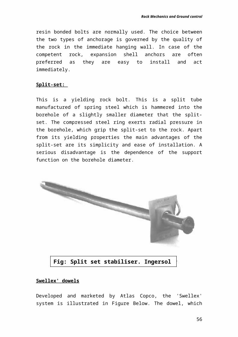
Fig: Components of an expansion shell
Advantages: Bolts can be tensioned immediately after installation and grouted at a later stage when short-term movements have ceased. Very reliable anchorage in good rock and high bolt loads can be achieved.Disadvantages: Relatively expensive. Correct installation requires skilled workmen and close supervision. Grout tubes are frequently damaged during installation and check by pumping clean water before grouting is importantApplications: Mechanically anchored bolts without grout used extensively in mining.
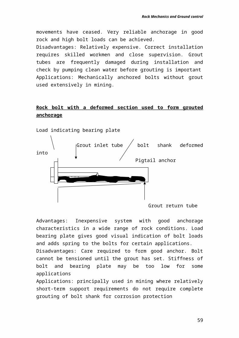
Rock bolt with a deformed section used to form grouted anchorage
Load indicating bearing plate
Grout inlet tube bolt shank deformed into Pigtail anchor
Grout return tube
44
Rock Mechanics and Ground control
Advantages: Inexpensive system with good anchorage characteristics in a wide range of rock conditions. Load bearing plate gives good visual indication of bolt loads and adds spring to the bolts for certain applications.Disadvantages: Care required to form good anchor. Bolt cannot be tensioned until the grout has set. Stiffness of bolt and bearing plate may be too low for some applicationsApplications: principally used in mining where relatively short-term support requirements do not require complete grouting of bolt shank for corrosion protection
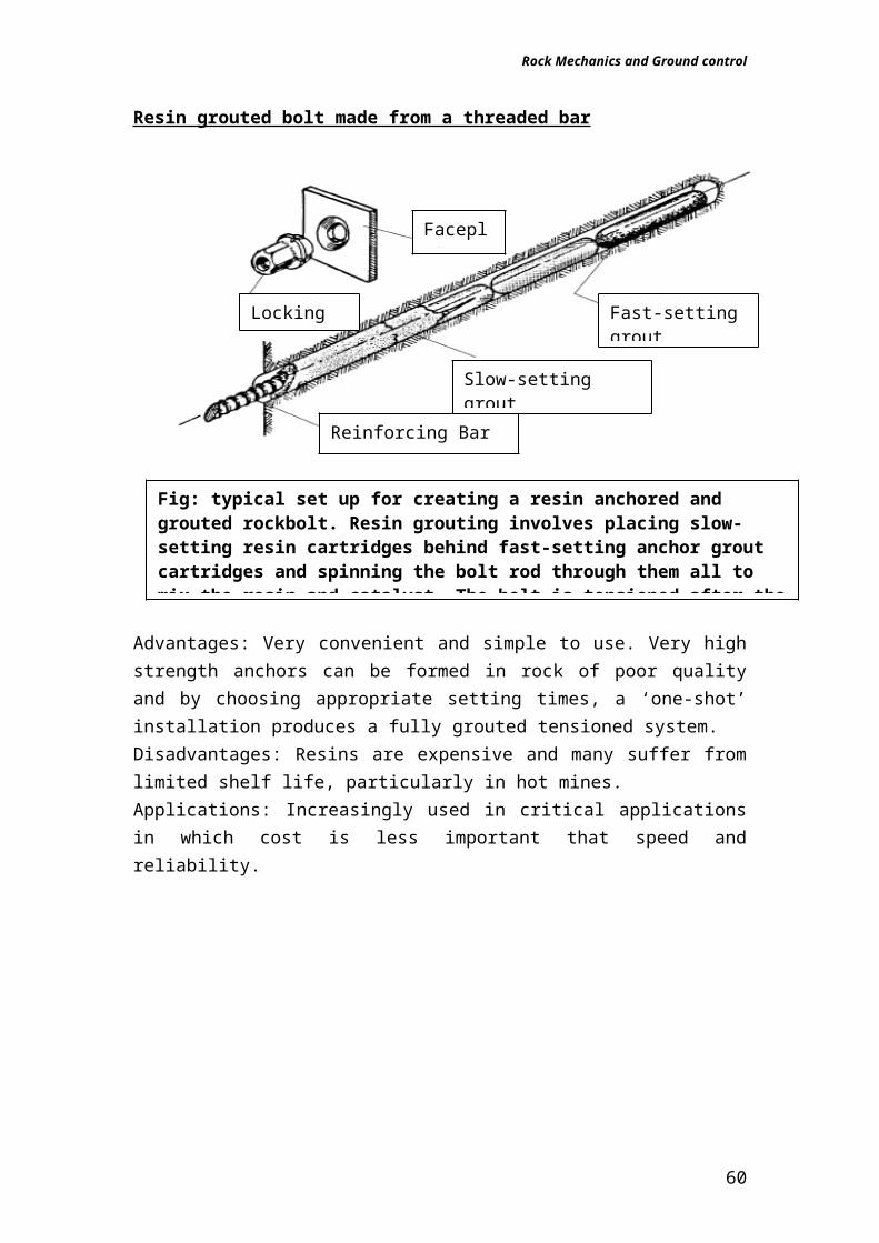
Resin grouted bolt made from a threaded bar
Advantages: Very convenient and simple to use. Very high strength anchors can be formed in rock of poor quality and by choosing appropriate setting times, a ‘one-shot’ installation produces a fully grouted tensioned system.Disadvantages: Resins are expensive and many suffer from limited shelf life, particularly in hot mines.Applications: Increasingly used in critical applications in which cost is less important that speed and reliability.
45
Faceplate
Locking Nut
Reinforcing Bar
Slow-setting groutcartridges
Fast-setting groutcartridges
Fig: typical set up for creating a resin anchored and grouted rockbolt. Resin grouting involves placing slow-setting resin cartridges behind fast-setting anchor grout cartridges and spinning the bolt rod through them all to mix the resin and catalyst. The bolt is tensioned after the fast-setting resin has set and the slow-setting resin sets later to grout the rod in place
Rock Mechanics and Ground control
Grouted dowel made from reinforcing bar
Advantages: Simple and inexpensive.Disadvantages: Cannot be tensioned and hence must be installed before significant deformation on the rock mass has taken place. Applications: Widely used for light support duties and for supporting ventilation tubing, pipework and similar services
Load-deformation characteristics of rock bolts
1. Expansion shell anchored rockboltSteel rod diameter: 17.28 mmUltimate tensile strength of bolt shank: approximately 12.7 tonnesExpansion shell anchor: Bail type three wedge anchorAt the pre-load of 2.25 tonnes, no deformation of the face plate.At a load of 4 tonnes, the face plate has deformed 9.5 mm and is completely flat, the bolt shank has deformed an additional 3.5 mm giving a total deformation of 13 mm at 4 tonnes load.Failure initiates at a load of 8 tonnes and a deformation of 25 mm with progressive failure of the expansion shell anchor in which the cone is pulled through the wedge. Maximum load is 9 tonnes at a deformation of 35 mm.
2. Cement grouted steel rebarSteel bar diameter: 20 mmUltimate tensile strength of steel rebar: 18 tonnesFaceplate: flat plate
46
RebarCement grout
Faceplate
Fig: Grouted dowel using a Deformed bar inserted into a grout-filled hole
Rock Mechanics and Ground control
Borehole diameter: 32 mmCement grout: 0.35 water/cement ratio grout cured for 11 daysAt a load of 15 tonnes and an elastic deformation of about 1.5 mm, a sudden load drop is characteristic of hot rolled rebar steel.Maximum load is 18 tonnes at a deformation of 30 mm.
3. Resin grouted steel rebarSteel rebar diameter: 20 mmUltimate tensile strength of steel rebar: 18 tonnesFaceplate: flat plateBorehole diameter: 32 mmResin grout: Five 580 mm long, 27 mm diameter polyester resin cartridges. Curing time60 minutes. Mixed by rotating rebar through cartridges in the boreholeAt a load of 15 tonnes and an elastic deformation of about 1.5 mm, a sudden load drop is characteristic of hot rolled rebar steel.Maximum load is 18 tonnes at a deformation of 20 mmThe resin is stronger than the cement grout and local fracturing and bond failure in and near the joint is limited as compared with the cement grouted rebar, leading to a reduced ultimate displacement at rebar failure.
4. Resin grouted fibreglass rodFibreglass rod diameter: 22 mmUltimate tensile strength of fibreglass rod: 35 tonnesFaceplate: special design by H. Weidmann AG. Switzerland Borehole diameter: 32 mmResin grout: Five 580 mm long, 27 mm diameter polyester resin cartridges. Curing time 60 minutes. Mixed by rotating fibreglass rod through cartridges in the boreholeAt approximately 1.5 tonnes load, failure of the fibreglass/resin interface initiates and starts progressing along the rod. As bond failure progresses, the fiberglass rod deforms over a progressively longer 'free' length.General bond failure occurs at a load of approximately 26 tonnes and a deformation of 25 mm.The ultimate capacity of this assembly is determined by the bond strength between the resin and the fibreglass rod and by the relatively low frictional resistance of the fibreglass.
5. Split Set stabiliser, type SS 39Tube diameter: 39 mmUltimate tensile strength of steel tube: 11 tonnesFaceplate: special design by manufacturer (see Figure 12.8)Borehole diameter: 37 mm
47
Rock Mechanics and Ground control
Dowel starts to slide at approximately 5 tonnes and maintains this load for the duration of the test which, in this case, was to a total displacement of 150 mm
6. EXL Swellex dowelTube diameter: 26 mm before expansionUltimate tensile strength of steel tube: 11.5 tonnes (before expansion)Type of face plate: Domed plate Borehole diameter: 37 mmPump pressure for expansion of dowel: 30 MPaAt 5 tonnes load the dowel starts to deform locally at the joint and, at the same time, 'bond' failure occurs at the joint and progresses outward from the joint as the load is increased. General 'bond' failure occurs at 11.5 tonnes at a deformation of approximately 10 mm. The dowel starts to slide at this load and maintains the load for the duration of the test which, in this case, was to 150 mm.
BEARING PLATE OPTIONS
48
A. Domed dogear washer B. Flat dogear washer
C. Domed washer D. Flat washer
E. Ribbed dogear washer
Rock Mechanics and Ground control
PROFILES
Flat Flat washers are simple plates, provided with a hole for the bolt.
Domed The surface of the plate is pressed into a domed profile. Dome washers are selected for applications where the hole and the rock surface are not at right angles, for example angled holes or uneven rock surface. Used with a spherical seat or a ball-nosed nut the washer is able to articulate under the seat enabling self-alignment and ensuring flush contact with the rock surface. The hole in the domed washer is therefore necessarily of a greater diameter than the bar diameter. The domed profile also provides greater pull-through strength, enabling the steel content to be optimised.
Ribbed The surface of ribbed washers is pressed into four ribs, radiating from a domed central portion around the hole. The ribbed profile provides strength and stiffness. Ribbed washers are selected for applications where bolts are installed at right angles to the plane of the rock and where flat rock surfaces are experienced. The hole size provides a loose fit for the bar but does not allow excessive play.
Dogears Most washers are provided with a turned-down (dogeared) corner equipped with a hole. These enable the attachment of lightweight services or airflow direction indicators.
ROCK MOVEMENT INDICATORS
DESCRIPTION: SPACEMAN ROCK MOVEMENT INDICATOR
The SPACEMAN rock movement indicator is a dial type displacement gauge used as a “tell tale” to indicate progressive slow strata separation. The SPACEMAN comprises a base unit with a faceplate dial and indicator needle and an extension rod equipped with a point anchor. The rod is inserted into a borehole, the depth of which is determined to be in competent ground beyond the expected separation planes. The faceplate is located flush against the rock. Any rock movement results in the faceplate moving away from the anchor point. The spiral drive of the indicator needle amplifies any such movement, thus indicating any slight displacement as a discernible rotation of the needle. Typically, SPACEMAN rock movement indicators are installed at roadway intersections in bord-and-pillar coal mines, but can be used in any environment where strata separation needs to be monitored.
49
Rock Mechanics and Ground control
The purpose of the device is to indicate incremental movement of the rock in order that timely remedial action can be taken. The SPACEMAN is not a precise measuring instrument, serving rather to monitor and compare progression over a period, usually days.
FEATURES• Permanent installations• Early warning of strata separation• Very slight rock movement is discernible• Ease of installation.• Calibrated faceplate• Robust steel construction
PropsProps made from steel are widely used to support tabular excavations. Depending on the method which is being used to introduce yield properties into what would otherwise be rigid support structure, one distinguishes between 1) friction type props (now outdated) and 2) hydraulic props.The hydraulic prop consists of a piston, a cylinder, a setting and a yield valve.
ShotcreteShotcrete is pneumatically applied concrete used to provide passive support to the rock surface. It is normally used in connection with steel mesh, steel or timber laggings or steel plates In recent years the mining industry has become a major user of shotcrete for underground support. It can be expected to make its own contributions to this field as it has in other areas of underground support. The simultaneous working of multiple headings, difficulty of access and unusual loading conditions are some of the problems which are peculiar to underground mining and which require new and innovative applications of shotcrete technology. An important area of shotcrete application in underground mining is in the support of 'permanent' openings such as ramps, haulages, shaft stations and crusher chambers. Rehabilitation of conventional
50
Threaded socket
Indicator needle
Dial
Extension rod
anchor
Rock Mechanics and Ground control
rockbolt and mesh support can be very disruptive and expensive. Increasing numbers of these excavations are being shotcreted immediately after excavation. The incorporation of steel fibre reinforcement into the shotcrete isan important factor in this escalating use, since it minimises the labour intensive process of mesh installation.
Shotcrete technologyShotcrete is the generic name for cement, sand and fine aggregate concretes which are applied pneumatically and compacted dynamically under high velocity.
Dry mix shotcreteAs illustrated in Figure 15.1, the dry shotcrete components, which may be slightly pre-dampened to reduce dust, are fed into a hopper with continuous agitation. Compressed air is introduced through a rotating barrel or feed bowl to convey the materials in a continuous stream through the delivery hose. Water is added to the mix at the nozzle. Gunite, a proprietary name for dry-sprayed mortar used in the early 1900's, has fallen into disuse in favour of the more general term shotcrete.
Wet mix shotcrete
In this case the shotcrete components and the water are mixed (usually in a truck mounted mixer) before delivery into a positive displacement pumping
51
Pre-dampened shotcrete mix
Compressed Air
Water Injection
Compressed air
Fig: Simplified sketch of a typical dry mix shotcrete system
Rock Mechanics and Ground control
unit, which then delivers the mix hydraulically to the nozzle where air is added to project the material onto the rock surface.
Pillar SystemsPillars are used in various forms for a great variety of purposes in all types of underground mining. It can be stated safely that no minerals have been or are being extracted by underground methods without employing pillars either as main support elements or in some secondary role
Classification of pillarsThere are three type’s of pillars, which are:
I. Support pillarsThis category includes all situations where the main ground control for the hanging wall is provided by a system of pillars an economic manner. Its popularity has been due to its simplicity, which usually results in low mining costs. It is normally used to extract minerals at relatively shallow depths. In such situations strip or open pit mining is its principal competitor. Its main disadvantage is that it results in relatively high losses in reserves and these losses rapidly increase with depth. In pillar mining the aim is to minimise the ore locked up in pillars to a level commensurate with the safety of the mine.
II. Protective PillarsThe purpose of protective pillars is to protect either surface structures or underground mining excavations or to separate one mine from its neighbour. Consequently these pillars might be referred to as, not only protective pillars
52
Vacuum helps to restore pumping tube to normal shape Air and accelerator
Air pipe
Rubber nozzle tip
Wet mix shotcrete
Rotating rollers
Rotating bladesSuction
Roller
Pumping Tube
Fig: Typical type of wet mix shotcrete machine
Rock Mechanics and Ground control
but also shaft pillars roadway pillars or boundary pillars. The function of these pillars is very different from that of supporting pillars. In the case above the size of the pillar is determined by the requirement the undermined hanging wall be adequately supported. The main consideration in designing protective pillars is to ensure the integrity of the structures to be protected. Usually therefore, no considerations of pillar strength are involved in determining the dimensions of these pillars.
III. Control PillarsRockburst is, the most serious strata control problem. This hazard becomes more crippling in deep level mining of tabular deposits in hard rock. The magnitude of energy changes is determined by the amplitude of hanging-wall and footwall convergence and ride. Thus to reduce induced energy changes that cause rockbursts it is necessary to decrease these relative movements components. This is best achieved by leaving unmined a systematic layout of pillars for the control of the relative displacement of the walls of mining excavations. Control pillars are usually of such geometry that their width-to-height ratio is well in excess of 10. Such pillars as a rule do not fail provided the rock mass above and below them is able to provide the necessary constraint.
BackfillBackfill is the term for material used to fill voids (empty stopes) created by mining activity.“The reasons for putting backfill underground range from providing regional support to disposal of a waste product. The fill serves many functions, although it is generally considered in terms of its support capabilities. Other than its own body weight, backfill is a passive support system that has to be compressed before exerting a restraining force. Backfill has little effect on the stress distribution in the surrounding strata. It can, however, have a considerable effect on the strength of a rock structure, even if it only prevents the rock from unraveling. This allows the rock to continue support even though fractured. To maximize support, the fill should be placed as soon as possible to take advantageof wall closure.
SelectionThe optimum backfilling method to be used at a proposed mine is clearly related to the mining method. If the mining method was already determined, the selection procedure is simplified. A problem remains in that the selection is often made on the basis of current technology. (When it comes to being state-of-the-art, backfill technology has a short shelf life.) A remedy is to evaluate research work now in progress, and then design a backfill system that is flexible enough to best accommodate anticipated advances in
53
Rock Mechanics and Ground control
technology. For example, two new mines were designed with dual-purpose backfill plants that can deliver both paste fill and HF.
Types of BackfillThe following types of backfill employed in rock mines are dealt with in the text of this chapter.
Rock fill Cemented Rock Fill (CRF) HF CHF (normal and high density) Concrete fill Paste fill Ice fill (permafrost regions)
Rock FillOriginally, backfill consisted of waste rock from development and hand picked from broken ore. Some of the larger mines quarried rock and dropped it down fill raises to the mine workings. Filling with rock alone is seldom practiced today except for filling tertiary stopes.
Cemented Rock FillCRF originally consisted of spraying cement slurry or CHF on top of stopes filled with waste rock.. Today, a cement slurry is added to the waste rock before (or as) the stope is filled. In mostcases, rock is quarried on surface and dropped to the mining horizon through a fill raise. Trucks or conveyors are used for lateral transport underground.The advantages of CRF include a high strength to cement content ratio and provision of a stiff fill that contributes to regional ground support. CRF is still selected for some new mines and many operators prefer this system.
Hydraulic FillThe first hydraulic fills consisted of a portion of the mill (concentrator) tailings that would otherwise have been deposited on surface. The mill tailings were cycloned to remove fines (slime fraction) so that the contained water would decant. This fill was transported underground as slurry, hence the term “hydraulic fill.” Initially, HF was sent underground at approximately 55% solids, since this is the typical underflow from a thickener and the pulp density normally used for tailings lines. When the grind from the mill was too fine for decanting in the stopes, alluvial sand was employed instead of tailings. This type of HF isoften called sand fill. Particles of alluvial sand are naturally rounded enabling a higher solids content to be pumped than HF made from cycloned tailings.
Cemented Hydraulic Fill
54
Rock Mechanics and Ground control
Portland Cement (binder) added to hydraulic fill provides strength. Later, it was found economical to replace a portion of the cement with fly ash (pozzolan) and occasionally a portion was replaced with ground slag, lime, or anhydrite. Normal (and high-density) CHF is employed at many hard rock mines worldwide. If cement is added to a hydraulic backfill at a ratio of 30:1, the backfill provides better support for pillars and wall rocks. One of the main problems with hydraulic fill and CHF is the requirement to bleed (decant) excess water from the filled stope. The dirty decanted water, along with flush water, picks up slimes and transports them to the mine sumps. The decant from CHF may contain particles of fresh cement (not yet hydrated), which has been blamed for causing hang-ups in ore passes. For these reasons, miners have directed attention towards producing HF with less contained water. As a result of these
Concrete FillCement-rich (1:2 cement to solids ratio) HF was once used for mats where poor ground conditions dictated undercut-and-fill mining. Since the major cost component of backfill is the cement, this fill is not economical. To make the mats less expensive, the mats were then made from ready-mix concrete, which has 10-12% cement content for a standard 20 Mpa mix. In some cases, the pour was completed above the mat with weak ready-mix concrete produced from the same batch plant
Paste FillThe ready-mix concrete required for undercut-andfill mining was replaced with a cemented fill using mill tails that did not require cycloning (“total tails”). The first paste fills contained a coarse aggregate fraction (sink-float product), similar to a regular concrete mix, which permitted transport at very high solids content (?88%) and resulted in high strengths with respect to the amount of cement. Cement was added at the stope entry. Today, paste fill is used to replace hydraulic fill without benefit of the coarse aggregate fraction and with cement mixed in before transporting underground.
Ice FillIce has long been proposed as backfill in permafrost regions; however, to date, ice has only been used in Norway and the CIS (Russia).
Chapter Eight: Mining Methods and Support Type Relationships
55
Rock Mechanics and Ground control
Pillar design criteria
1) Room and pillar mining method
A y
B x Room
Pillar
Pillars must have same dimensions and must be regularly spaced. The pillars have a uniaxial strength that is dependent on mostly the length and width
Tributory theory It is used to determine the pillar load; it is applied also to describe the average state of axial stress of a pillar. This theorem bases its analysis on the elementary motions of static equilibrium, which are then used to establish an average state of stress in the support elements. It suggests that the strength of a pillar is related to both its volume and geometric shape with the effect of volume on the strength being analysed in terms of the distributions of cracks, natural fractures and other defects in the rock mass.Assumptions used are:
i. It is assumed that the load is uniformly distributed over the crossectional area of the pillar.
ii. Each pillar supports the volume of rock that is the sum of the crossectional area of the pillar plus a portion of the room area(ABCD)
y
56
Rock Mechanics and Ground control
A B x
x/2
Y/2
a
b D C
iii. The area is only subjected to vertical pressure which is constant over the mined area
σp =ρgh(1-e)-1
where σp – pillar load ρ – density of pillar g – acceleration due to gravity h – height of pillar e – Area rate of extraction = Area of ABCD (c 2 ) -Area of AB(w 2 )
Area of ABCD (c2) There are three critical factors in pillar design that is:
Pillar load σp
Pillar strength S Factor of safety
Factors affecting pillar load Ore extraction ratio =area mined out/total area of orebody Geometric shape of the pillar Maximum load the pillar can sustain or carry Volume of the pillar The inclination of the pillar influenced by the orebody angle Influence of gravity
Factors affecting Pillar strength Operating area (defined by the pillar dimensions perpendicular
to pillar axis) Inherent strengthening of pillar material Height and width of the pillar Area supported by the pillar
FS= Total force available to resist Force tending to induce failure
= Pillar StrengthPillar stress
This is the ratio of the pillar strength and the average pillar stress and it shows the resisting force of the material to the force exerted at fracture or yield. It is mainly used to determine when a pillar is safe and stable or expected to fail. If the factor of safety is greater than 1 there is safety and stability. But it is advisable for mining operation for it to be at least 1.5 and if less than 1 pillar failure is expected.
Example:A 15m square pillar at a depth of 253m, with a board width of 5m has a factor of safety of 1.5. The room height is 3m and the seam thickness(m) is 5m.
1. Calculate the area rate of extraction2. Calculate the volumetric extraction (r)3. Calculate the pillar strength
Solution:1. Area rate of extraction e = 1 – w 2
c2
where c= w + b = 15 + 5 = 20m
. ‘ . e = 1 - 15 2 202
= 0.4375 * 100% = 43.75%
2. Volumetric extraction = h (1 – w2/ c2) m = h(e) m = 3/5 * 43.75% = 26.25%
Tutorial1) Given an orebody 2.6m thick, depth below surface 500m
ρore = 2.4t/m3 ρwaste = 2t/m3 SF = 2UCS of ore = 400t/m3 Calculate
I. Pillar widthII. Area extraction ratio
III. Pillar stress2) Given an orebody 3m thick, depth below surface 600m
ρore = 2.6t/m3 ρwaste = 2.2t/m3 SF = 1.5UCS of ore = 5000t/m3 Calculate
I. Pillar widthII. Area extraction ratio
III. Pillar stress
Mining Practise: Shallow mining
Potential Problems
Long tensile zone Potential failures due to tensile fractures and geological discontinuities Hanging wall beam failure Rock falls Key block failure
Mitigation Strategy
Aim to control the tensile zone to arrest fall of ground Use pillars (they must incorporate geological discontinuities and put
them in low grade areas) Use stiff load supports these are capable of holding loads when slight
movements occur e.g. a mine pole, rock tendons/ rock bolts, props(cam lock jack, hydraulic jack)
Intermediate Depth mining
Potential Problems
59
Rock Mechanics and Ground control
Stress concentration low to moderate Blast initiated fractures Stope closures
Mitigation Strategy Avoid going beyond the critical stope span of the stope Incorporate regional pillars around geological discontinuities Use stiff support in bad areas Intermediate depth is not very critical in terms of rock bursts and
seismicity but tunnels/drives below stopes should be over stoped
Shallow mining
Potential Problems
There are geological problems associated with depth - dykes, sill, shear zones and seismically active faults.
Stope closure is very fast Total closure is common even when the stope span is very small
Mitigation Strategy Tunnels must be overstoped to protect them from excessive stress
(pillars/protection pillars) are compulsory around seismically active dykes
Slope support might include using rapid trelding hydraulic props If rock bursts cannot be controlled stability pillars and back fill must be
used
Chapter Nine: Special Blasting Techniques
There are many blasting situations which require specialized design techniques, a few of which will be discussed in this section. The two most important are pre-split blasting and smooth-wall blasting. Both techniques are important but if pre-split works then smooth-wall will not and vice-versa. Both use decoupled charges often N.G. explosives to ensure propagation either using special small diameter charges or by spacing.
Presplitting
With this method, a continuous fracture, which will form the final surface of an excavation, is generated in the absence of a local free face. If hole spacings are sufficiently small, the explosive charges adequate and the geomechanical conditions satisfactory a fracture surface is developed over the smooth
60
Rock Mechanics and Ground control
surfaces containing the axes of the blast holes. The charges in presplitting are usually initiated simultaneously with detonating cord and trunk lines or instantaneous electric blasting caps. There are two theories as to why cracks are preferentially formed when two closely spaced blast holes are fired.
Instantaneous Initiation Theory
It is considered that when two adjacent are fired simultaneously radial cracks tend to propagate equally in all direction until the oncoming tangential tensile wave from the adjacent holes collides head on with the radial crack, which is extending towards this hole. From that instant, the tip of this particular radial crack experiences an extra tensile tangential stress, which encourages its extension. The lengthening of the crack then proceeds, under the wedging action of the invading explosion gases, at a faster rate than that of the others. The extension of the remaining cracks slows down and eventually stops. If the gas pressure is to be effective in extending selected fractures, it must be maintained until the fracture is complete. Hence adequate stemming is required.
Delay Firing
Consider two blast holes A and B in a stress free isotropic rock fig A. Hole A is detonated before hole B.Fig A: Delay firing
Hole Hole A 1 B 2 Pd Pd First detonation Second detonation Hole B is initiated as the stress wave from A passes over it. The transient local stress field around hole B is effectively uniaxial, of magnitude Pd and oriented to the centre of the holes. Superimposition of the stress wave from the detonation of B on these boundary stresses generates the highest tensile stresses at 1 and 2 and cracks are preferentially created here. The gas promotes the extension of these, the longest cracks.
These mechanisms require either a very short delay or a short delay. Very long or no delay will give no pre-split by this mechanism. If however there is significant in-situ stress at right angles to the desired direction of the pre-split then the initial fractures around each blast hole will form preferentially parallel to the direction of the principal stress and the system will be inoperative.Hence in underground excavations, where the principle stress is usually vertical, pre-splitting will work adequately on the sides of an excavation but
61
Rock Mechanics and Ground control
not across the roof. Under these circumstances smooth-wall blasting should be employed.
Smooth Blasting
It involves the development of the ultimate surface of the excavation by controlled blasting in the vicinity of a penultimate free face. Holes are initiated with short delay between adjacent holes, and the burden on holes exceeds the spacing. Successful smooth blasting requires especially careful and accurate drilling, it is often forgotten that the result cannot be better than drilling. In smooth-wall blasting a single row of holes is again drilled along the neat excavation line loaded with light, well distributed charges, and fired either together with the field blast or after it. Similar to presplitting, smooth blasting requires stemming at the collar but not for the entire length of the hole.
Chapter Ten: Instrumentation and Monitoring
Monitoring is the surveillance of engineering structures, either visually or with the help of instruments. In a general rock mechanics context, monitoring may be carried out for four main reasons.
To record the natural values of, and variations in, geomechanical parameters such as ground levels and seismic events before the initiation of the mining project.
To ensure safety during construction and operation by giving warning of the development of excess ground deformations, groundwater pressures and loads in support elements.
To check the validity of the assumptions, conceptual models and values of the rock mass properties used in design calculations.
To control the implementation of ground treatment and remedial works such as ground freezing during shaft sinking or tunnelling through water bearing ground, grouting, drainage or the provision of support by tensioned cables.
In mining rock mechanics most monitoring is carried out for the second and third of these reasons.
Monitoring systemsThe instrumentation system used to monitor a given variable will generally have three different components. A sensor or detector responds to changes in the variable being monitored. A transmitting system which may use rods, electrical cables, hydraulic lines or radiotelemetry devices, transmits the sensor output to the read out location. A read out and or recording unit such
62
Rock Mechanics and Ground control
as a dial gauge, pressure gauge, digital display or magnetic tape recorder converts the data into a usable form.
Modes of operationThe mode of operation of the sensing, transmission and read out systems used in monitoring devices may be mechanical, optical, hydraulic or electrical.Mechanical systems:They are often the simplest, cheapest and most reliable methods of detection, transmission and read-out. Mechanical movement detectors use a steel rod or tape, fixed to the rock at one end, and in contact with a dial gauge or electrical measuring system at the other. The main disadvantage of mechanical systems is that they do not lend themselves to remote reading or to continuous reading.Optical systems:They are used in conventional, precise, and photogrammetric surveying methods of establishing excavation profiles, measuring movements of excavation boundaries, and recording natural and induced fractures.Hydraulic or Pneumatic:Here diaphragm transducers are used for measuring water pressures, support loads, cable anchor loads, normal components of stress and settlements. In all cases the method of operation is the same.Electrical:These devices probably provide the most common basis of the instruments currently used to monitor the performance of rock masses surrounding mining structures. Examples of electrical devices are Electric resistance strain gauges, Vibrating wire sensors, self-inductance instruments and linear variable differential transformers.
MEASUREMENT OF STRAIN USING A STRAIN CELL
63
Rock Mechanics and Ground control
Chapter Twelve: Mining Induced Subsidence
Types and effects of mining induced subsidence
Subsidence is the lowering of the ground surface following underground extraction of the orebody. Subsidence is produced, to a greater or lesser degree by almost all types of underground mining. Surface displacement may
64
a) Borehole drilled to require depth and end flattened and polished with diamond tools
b) Strain cell bonded on to end of borehole and strain readings recorded
c) Borehole extended with diamond core barrel thereby stress-relieving core
d) Core with strain cell attached removed
Fig: A C.S.I.R strain cell bonded onto a rock core recovered from a borehole
Rock Mechanics and Ground control
result from the redistribution of stresses associated with or from mining related such as dewatering.Subsidence can be regarded as being of two types i.e. continuous and discontinuous.
Continuous or Trough subsidence: it involves the formation of a smooth Surface subsidence profile that is free of step changes as shown below.
Subsidence profileOriginal surface
Trough subsidence Over a longwall Extraction
The resulting displacements of surface points may be of only elastic orders of magnitude when compared with the dimensions of the subsiding area or the mining depth. This subsidence is associated with the extraction of thin, horizontal or flat dipping ore bodies overlain by weak non-brittle sedimentary strata. It may results from longwall mining of coal, but has also been associated with the extraction of a wide variety of other minerals e.g. sulphur, evaporates deposited in sedimentary environments.
Discontinuous Subsidence :
it is characterised by large surface displacements over limited surface areas and the formation of steps or discontinuities in the surface profile. It may be associated with a number of mining methods, may involve range of mechanisms, may develop suddenly or progressively.
Types of Discontinuous Subsidence
Crown Holes: arise from the collapse of the roofs of generally abandoned shallow open workings. Much of surface damage in walls in anthracite mines is due to this.Pillar collapse: in old shallow workings may lead to similar surface expressions of discontinuous subsidence as does crown hole formation. Such collapses may occur as a result of deterioration in pillar strength with time or the imposition of additional load on the pillar by surface construction.Chimney caving (piping or funnelling): involves the progressive migration of an unsupported mining cavity through the overlying material to the surface. The surface subsidence area may be of a similar plan shape and area to the
65
Rock Mechanics and Ground control
original excavation. Chimney caves have been known to propagate upwards to surface through several hundreds of metres.Plug subsidence: if a chimney formation is sudden rather than progressive, the phenomenon is sometimes known as plug subsidence. Generally plug subsidence is controlled by some structural feature such as a dyke or a fault which provides a plane of weakness whose shear strength is overcome at some critical stage of mining. This form of subsidence generally produces underground airblasts.
Design measures to limit subsidence
Partial extraction: in which substantial rib pillars are left between panels, has been successfully used to limit maximum subsidence and to produce a net subsidence profile that is free from horizontal strain and tilt over most of its width.Goaf treatment: by strip packing or hydraulic or pneumatic solid stowing can reduce the subsidence in a single panel by up to 50% depending on the nature and timing of the treatment. The largest reductions are obtained for solid stowing carried out immediately after mining.Harmonic extraction: involves the phased removal of the mineral from a critical area such that the ground surface is lowered smoothly and horizontal strains are minimised. The technique maybe used to protect structures that are especially important or susceptible to subsidence induced damage. The orientation of the structure with respect to the direction of face advance determines whether protection against the transverse or the longitudinal surface wave is more important.