ROCK SUPPORT SYSTEM IN INTERACTION WITH THE ROCK Boliden P-I. Marklund, D. Sandström LKAB L. Malmgren, A Nordqvist Luleå University of Technology E. Nordlund, U. Nyberg, D. Saiang, P. Zhang, H. Basarir, M.Westblom, S. Shirzadegan, K Perez
Transcript
ROCK SUPPORT SYSTEM IN INTERACTION WITH THE ROCK
BolidenP-I. Marklund, D. Sandström
LKABL. Malmgren, A Nordqvist
Luleå University of TechnologyE. Nordlund, U. Nyberg, D. Saiang, P. Zhang,
H. Basarir, M.Westblom, S. Shirzadegan, K Perez
Rock mass – rock support interaction
A
A
Rock mass – rock support interaction
A
A
A
Objective
General• Improve the understanding of the interaction between the
rock mass and the rock support system
Mining companies• Reduction of the number of production disturbances,
thereby decreasing the risk for personnel injury and production losses.
Project outline• Sub project
– Weak ore contacts and large deformations– Mining-induced seismicity
• Main activities– Field measurements – tests
• Kristineberg – Boliden: ~1200 m depth (has been done)• Malmberget – LKAB: ~850 m depth (Instrumentation starts 2011)• Optional: Garpenberg – Boliden
– Large scale field test - seismically loaded rock support• Kiirunavaara mine (has started)
– Numerical analyses• Conceptual analyses (has started)• Analyses of field experiments (has started)
Behaviour of drifts in weak rock
Squeezing conditions – Malmberget mine
Photo: LKAB
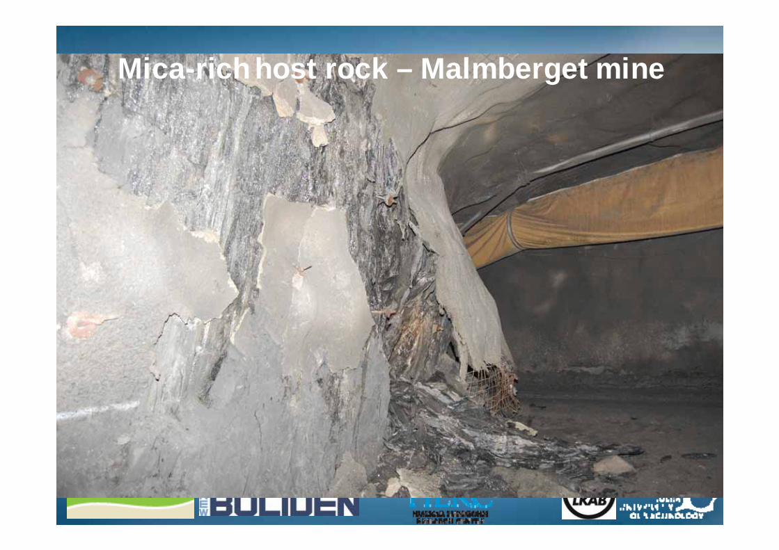
Mica-rich host rock – Malmberget mine
Field monitoring – Weak rock
Field test on rock support in the Kristineberg mine (March 2010)
• Objective–Increase the understanding of the
interaction: rock - rock support system–Evaluation of the D-bolt in the field
• Details–Stope length 50 m –Every second round D-bolt and every
second rebar
Instrumented stope
Talky schist ~ 0.5 - 1 m
Chlorite quartzite ~ 0 - 10 m
D-bolt
Damage in boreholes and in the footwallHangingwall
123456789 89 7896789
56789456789
34567892356789
1235678910
FootwallFootwall
Cut #4
Cut #4
Cut# 6
Cut #5
Additional measurements
Convergence J10 Cut #5
-200
-180
-160
-140
-120
-100
-80
-60
-40
-20
00 10 20 30 40 50
Days
Acc
. con
verg
ence
(m
m)
Maximum convergence in Cut #4
Convergence• Cut #4: Max = 80 mm• Cut #5: Max = 160 mm
Numerical analysis of static conditions
3D numerical analysis of laboratory tests• Evaluation of models for modelling of shotcrete – rock interaction
• Evaluation of models for rock – rock bolt interaction
Shotcrete
Rock block
Shear stress
Rock bolt
Not ”normal” profile
12345678910
1 – 10: Rounds
”Normal” profile
Analysis of the experimental stope – Cut #42D (”Pseudo 3D”) - Ongoing
Cut #3
Cut #2
Cut #1
Cut #4Real geometry
Cut #4
Cut #3
Cut #2
Cut #1
Analysis of the experimental stope – Cut #42D (”Pseudo 3D”) - Ongoing
Sensitivity analysis of geometry
Cut #3
Cut #2
Cut #1
Cut #4
Analysis of the experimental stope – Cut #42D (”Pseudo 3D”) - Ongoing
3D – Will start later
Sensitivity analysis of geometry
Sub-project: Mine-induced seismicity
Different source mechanisms
A
A
A - A
A
A - A
Fault slip/Shear rupture
Strain burst
• Strain bursts due to high statoc stresses• Fault slip event
– Superposition of static and dynamic stresses Higher stress level exceeding the compressive strength
– Shaking Block and wedge fallouts– Ejection (Close to fault slip event)
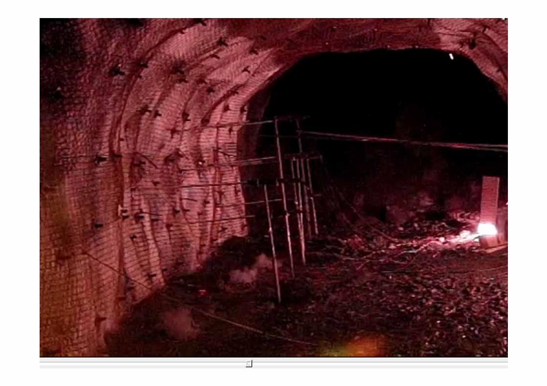
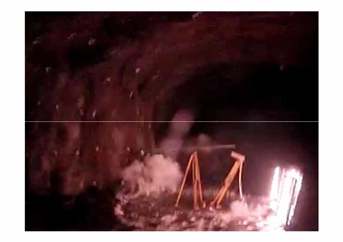
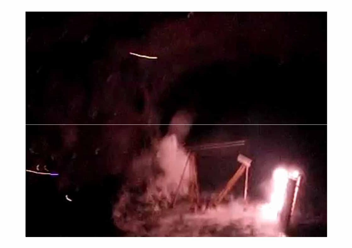
Mining induced seismicity
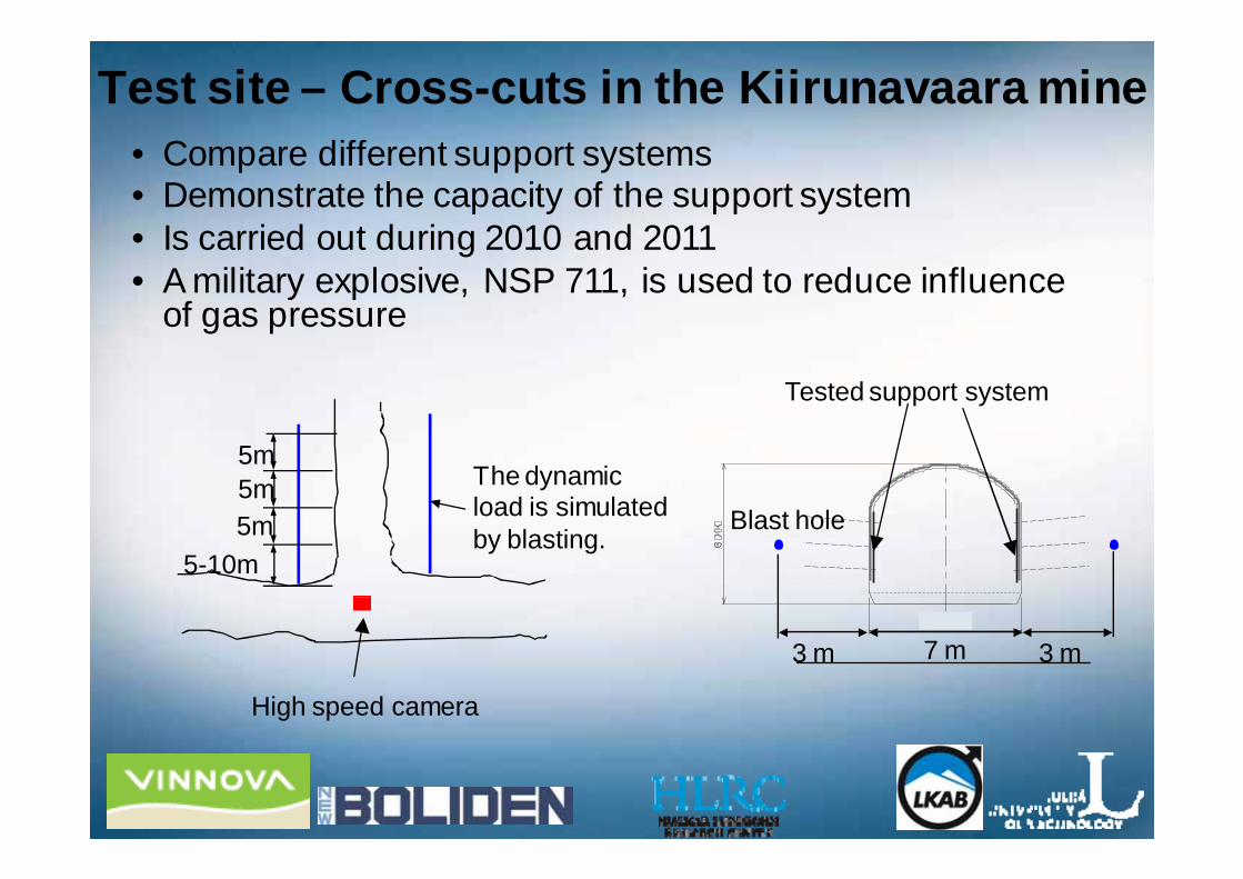
Test site – Cross-cuts in the Kiirunavaara mine
The dynamic load is simulatedby blasting.
High speed camera
5m5m5m
5-10m
7 m
Tested support system
Blast hole
3 m3 m
• Compare different support systems• Demonstrate the capacity of the support system• Is carried out during 2010 and 2011• A military explosive, NSP 711, is used to reduce influence
of gas pressure
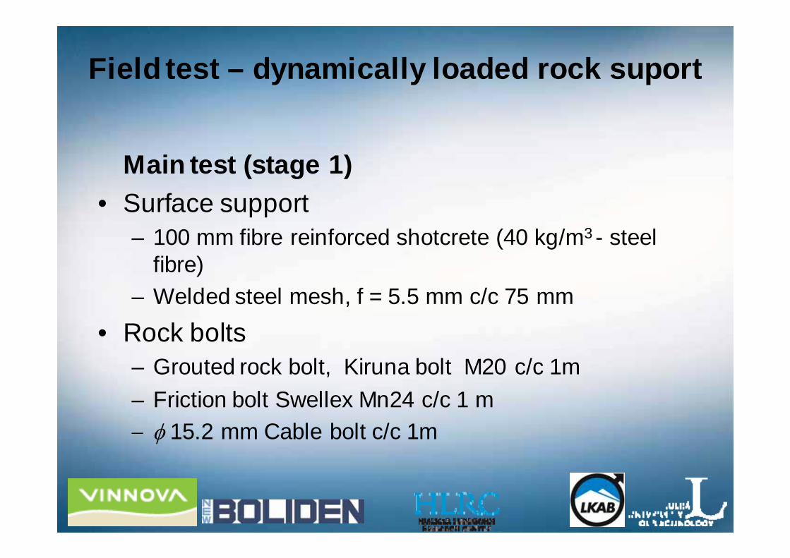
Field test – dynamically loaded rock suport
• Trial test– Objective: Design of the test
Critical charge density and evaluation of instrumentation • Main test (stage 1)
– Objective: Test of the standard support used at LKAB. • Main test (stage 2)
– Objective: Test of yielding rock bolts with the standard surface support.
• Main test (stage 3)– Objective: Compare different surface support
The rock bolt is the best one in Stage 2
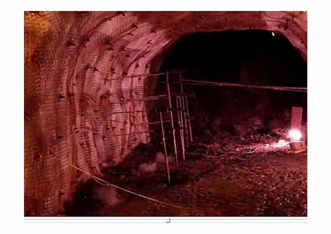
Zero test 1
Result
Before After
Zero test 1• Detonation (NSP 711)
– Gas pressure• The shock wave load < 1 ms after initiation. • Gas pressure loading 36 ms after initiation
• Acceleration, velocity and displacement– Maximum average-PPV 5.6 m/s– Deformation < 70 mm
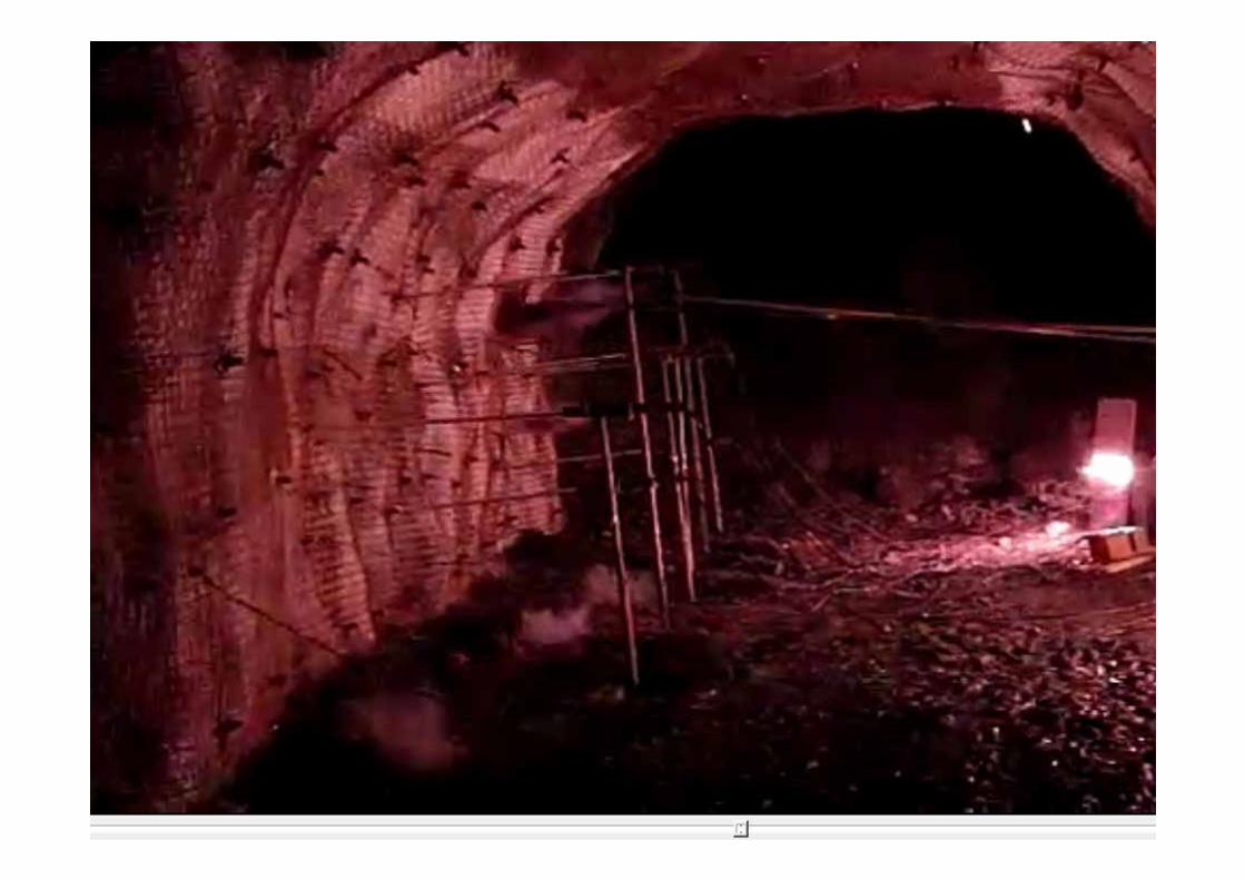
• What did not work as planned?– The largest charge diameter (Ø76 mm) gave
only limited damage to the rock support Charging too small
Zero test 2, 3 & 4• Zero test 2 (NSP 711)
– The larger charge incresed with 62% (6 inch hole diameter)– The smaller charge = the larger in Zero test 1– Result - Somewhat more cracks
Zero test 2, 3 & 4• Zero test 2 (NSP 711)
– The larger charge incresed with 62% (6 inch hole diameter)– The smaller charge = the larger in Zero test 1– Result - Somewhat more cracks
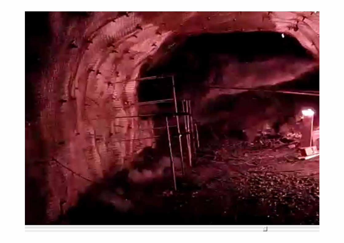
• Zero test 3 (Bulk emulsion)– The 6-inch hole in Zero test 2 was re-charged with bulk emulsion
25 kg/m 190% greater than the charge in Zero test 1– Result - Ejection
Total damage after Zero test 3
Zero test 2, 3 & 4• Zero test 2
– The larger charge incresed with 62% (6 inch hole diameter)– The smaller charge = the larger in Zero test 1– Result - Somewhat more cracks
• Zero test 3– The 6-inch hole in Zero test 2 was re-charged with bulk emulsion
25 kg/m 190% greater than the charge in Zero test 1– Result - Ejection
• Zero test 4 (NSP 711)– Only one charge density 133 % higher than in Zero test 1
Damage after Zero test 4
Summary Zero tests
• Ejection – occurs when the charge of NSP711 with a diameter of
120 mm is used (the length is 5 m)– does not occur when the charge diameter is 98 mm
• The position of the camera has to be changed to avoid vibrations from blast gases from the collar of the blasthole
• We know the way we will measure the deformations and damage
Numerical analasis of dynamic problems
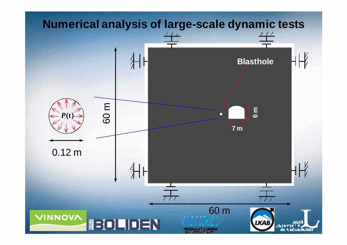
Numerical analysis of large-scale dynamic tests
60 m
60 m
7 m
6 m
Blasthole
0.12 m
P(t)
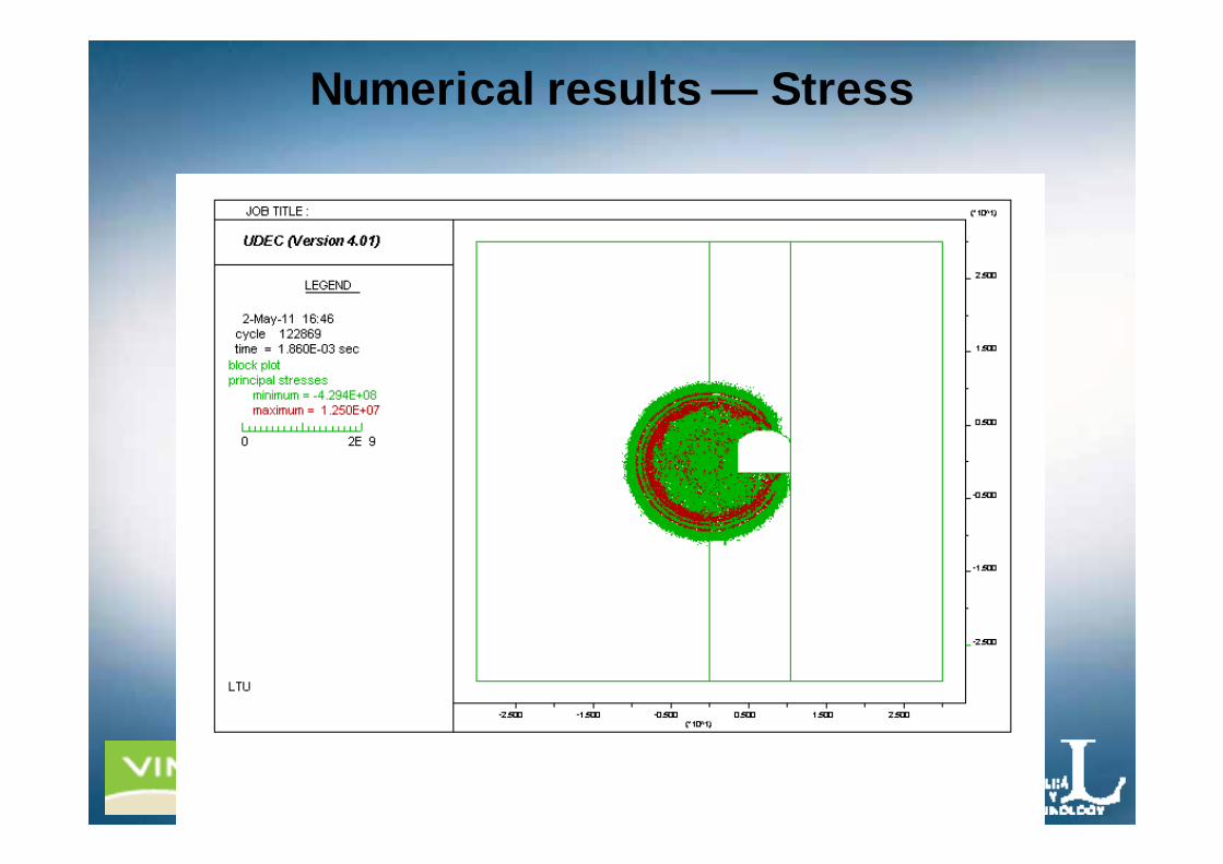
Numerical results — Stress
Numerical results — Stress
Numerical results — Stress
Numerical results — Stress
Numerical results — Stress
Numerical analysis of seismically loaded openings
• Response of a drift exposed to different wave types
• Response of drifts exposed to seismic loads
…Thank you!!
Presentation of the project idea• Conferences etc.
– Bergforskdagen 2010– SOMP Annual Meeting, Tallinn, Estonia, June, 2010– Sonora Mining Expo, Oct., 2010 – Workshop at the 2nd Australasian Ground Control Conf., Nov., 2010– Bergmekanikdagen, March, 2011
• Universities, companies etc.– University of Zambia, May, 2010– Polytechnic of Namibia, June, 2010– University of Dar es Salaam, Sept., 2010– Laurentian University Oct., 2010– Grupo Mexico, Mexico City, Oct., 2010– CFE, Mexico City, Oct., 2010
Field test – dynamically loaded rock suport
Trial test• Support system tested = Standard support in
seismically active areas– 100 mm fibre reinforced shotcrete (40 kg/m3- steel
fibre)– Welded steel mesh, f=5.5 mm c/c 75 mm– Friction bolt Swellex Mn24 c/c 1 m