8
| ROMI G 550 | ROMI G 550M ROMI G SERIES TURNING CENTERS TECHNICAL SPECIFICATIONS

| ROMI G 550 | ROMI G 550M
ROMI G SeRIeSTuRnInG CenTeRS
TeChnICal SpeCIfICaTIOnS

2
Capacity Swing over Z axis cover mm (in) 685 (26.97) 685 (26.97) Maximum cutting diameter mm (in) 550 (21.65) 550 (21.65) Maximum cutting length (between center) mm (in) 1,300 (51.18) 1,300 (51.18)Travel (X axis) mm (in) 280 (11.02) 280 (11.02)Travel (Z axis) mm (in) 1,300 (51.18) 1,300 (51.18)HeadstockSpindle nose aSa a2-8” a2-11” a2-15” a2-8” a2-11” a2-15”Spindle hole diameter mm (in) 104 (4.09) 142 (5.09) 182 (7.17) 104 (4.09) 142 (5.09) 182 (7.17) Speed rangeDirect drive rpm 2 ~ 2.500 2 ~ 2.000 1 ~ 1.500 2 ~ 2.500 2 ~ 2.000 1 ~ 1.500
With reduction gearbox range 1 rpm - 6 ~ 630 4 ~ 473 - - -range 2 rpm - 2 ~ 2.000 1 ~ 1.500 - - -
FeedsRapid traverse (X axis) m / min (ipm) 18 (0.70) 18 (0.70)Rapid traverse (Z axis) m / min (ipm) 24 (0.94) 24 (0.94)Tool Turret T type turret M type turretnumber of tools / stations un 12 12Tool holder type - ROMI BMT-75Tool section: square mm (in) 32 x 32 (1 1/4 x 1 1/4) 25 x 25 (1 x 1)Tool section: bar (diameter) mm (in) Ø 50 (2) Ø 50 (2) axial driven tool holder DIn 6499 - eR 40 (Ø 3 - Ø 26 mm)Radial driven tool holder DIn 6499 - eR 40 (Ø 3 - Ø 26 mm)Speed range (driven tool) rpm - 3 ~ 3.000Driven tool motor hp / kW - 10 / 7,5Index time: next tool (incl. unclamp and clamp) s 0,7 0,5Index time: 180° s 1,9 1,36Tailstock Tailstock body travel mm (in) 1,143 (45.00) 1,143 (45.00)Quill travel mm (in) 130 (5.12) 130 (5.12)Quill diameter mm (in) 120 (4.72) 120 (4.72)Tailstock body positioning - automatic automaticBody fixing - hydraulic hydraulic Quill activation - hydraulic hydraulic Quill taper hole MT 5 (built-in) 5 (built-in)Electrical specificationaC main motor (S3 - 60% rating) hp / kW 50 / 37 50 / 37Total installed power kVa 60 60Dimensions and weights (approximate) (*)floor space required mm (in) 5,400 x 2,130 (212.60 x 83.86) 5,400 x 2,130 (212.60 x 83.86)net weight kg (lbs) 7,200 (15.873) 7,200 (15.873)
Techinical specification ROMI G 550 ROMI G 550M
(*) Without chip conveyor
• 12-station programmable T turret, servomotor driven, horizontal axis, hydraulically clamped (ROMI G 550)
• 12-station programmable M turret, servomotor driven, horizontal axis, hydraulically clamped, BMT-75 type tool disk for static tools and driven tools (ROMI G 550M)
• automatic lubrication system with line filter and oil level sensor
• Ce safety regulation compliance (for european Community only)
• CnC fanuc 0i-TD, with 10,4” lCD color monitor
• Complete documentation on CD• Complete electrical installation
for 400 Vca, 50/60hz (Ce market) or 220 Vca, 50/60hz (uSa and other markets)
• Coolant cleaning system for guide covers
• Coolant system with 340 liters (49 gallons) tank capacity, with three coolant pumps for choice (2 bar / 29 psi, 7 bar / 102 psi or 15 bar / 218 psi) (a)
• fully enclosed splash guard with interlocked sliding safety door
• hydraulic unit (max. pressure 50 bar / 725 psi, 15 l/min / 4 gpm) and pressure control circuit for clamping device and tailstock
• longitudinal hinged belt chip conveyor (TCe)
• Sealed worklight• Set of wrenches for machine operation• Set of screws, nuts of leveling and base
plates for the leveling• Standard colors: Texturized epoxy
enamel Munsell Blue 10B-3/4 and Texturized epoxy Gray Ral 7035
• Tailstock with programmable automatic body position, hydraulically driven quill, with built-in live center MT-5
Standard equipment
• air conditioning for electrical cabinet• air cleaning system to remove chips
from the chuck• automatic door electric motor driven
with electronic sensor security system• auto power off• autotransformer 8 taps for 200 ~ 250
Vca or for 360 ~ 480 Vca, 50 / 60 hz• Coolant pumps offered (2 bar / 29 psi,
7 bar / 102 psi or 15 bar / 218 psi) (a)• Deep hole drilling support Ø 80mm with
reduction sleeves Ø 50 e 60mm (bar not
■ Ø 390 mm (Ø 15.35“), aSa a2-11”, Ø 115 mm (Ø 4.53“) thru-hole, foot switch included
■ Ø 500 mm (Ø 19.68“), aSa a2-15”, Ø 160 mm (Ø 6.30“) thru-hole, foot switch included
• hydraulic self-centering steady rest (SMWSlu 3.2), Ø 50 mm (Ø 1.97“) to Ø 200 mm (Ø 7.87“) capacity with pro-grammable body positioning by Z axis
• linear scale for X axis• M code external interface (6 codes)
Optional equipment
included) • Double foot switch for hydraulic chuck
and tailstock quill• foot switch for hydraulic chuck• foot switch for tailstock quill• hydraulically chuck (a): ■ Ø 315 mm (Ø 12.40“), aSa a2-8”,
Ø 90 mm (Ø 3.54“) thru-hole, foot switch included
■ Ø 390 mm (Ø 15.35“), aSa a2-8” , Ø 90 mm (Ø 3.54“) thru-hole, foot switch included
• Mist exhausting system• Oil skimmer• preparation for mist exhausting system• Remote diagnosis interface + ethernet
data server• Status light indicator• Steady rest (open) with rollers,
Ø 10 mm (Ø 0.40“) to Ø 300 mm (Ø 11.81“) capacity
• Tool setter• Two programmable chuck pressures• Wash gun
(a) Mandatory choice
3
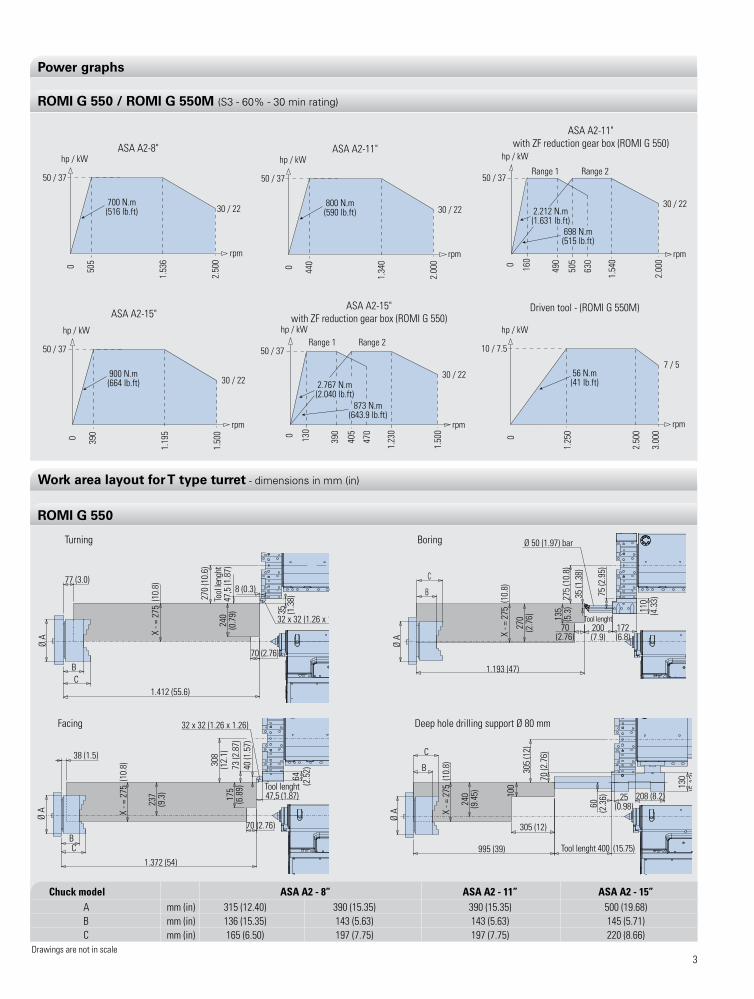
Power graphs
50 / 37
30 / 22
hp / kWASA A2-8"
0
rpm
505
1.53
6
2.50
0700 N.m(516 lb.ft)
50 / 37
30 / 22
hp / kW
ASA A2-11"with ZF reduction gear box (ROMI G 550)
0
rpm
505
1.54
0
2.00
0
490
630
160
Range 1 Range 2
2.212 N.m(1.631 lb.ft)
698 N.m(515 lb.ft)
50 / 37
30 / 22
hp / kW
ASA A2-15"with ZF reduction gear box (ROMI G 550)
0
rpm
405
1.23
0
1.50
0
390
470
130
Range 1 Range 2
2.767 N.m(2.040 lb.ft)
873 N.m(643.9 lb.ft)
50 / 37
30 / 22
hp / kWASA A2-11"
0
rpm
440
1.34
0
2.00
0
800 N.m(590 lb.ft)
50 / 37
30 / 22
hp / kW
ASA A2-15"
0
rpm
390
1.19
5
1.50
0
900 N.m(664 lb.ft)
10 / 7.5
7 / 5
hp / kW
Driven tool - (ROMI G 550M)
0
rpm
1.25
0
2.50
0
3.00
0
56 N.m(41 lb.ft)
ROMI G 550 / ROMI G 550M (S3 - 60% - 30 min rating)
Drawings are not in scale
Work area layout for T type turret - dimensions in mm (in)
38 (1.5)
X - =
275
(10
.8)
237
(9.3
)
308
(12.
1)
32 x 32 (1.26 x 1.26)
175
(6.8
9)73
(2.8
7)40
(1.5
7)
Tool lenght47,5 (1.87)
64 (2.5
2)
70 (2.76)
1.372 (54)
C B
Ø A
facing
X - =
275
(10
.8)
240
(9.4
5) 100
305
(12)
70 (2
.76)
305 (12)
995 (39)
60 (2.3
6)
Tool lenght 400 (15.75)
25(0.98)
208 (8.2)
130
(5.1
2)
Ø A
C
B
1.412 (55.6)
77 (3.0)
X - =
275
(10
.8)
270
(10.
6)
240
(0.7
9)
Tool
leng
ht47
,5 (1
.87)
8 (0.3)
32 x 32 (1.26 x 1.26)
35 (1.3
8)
C B
Ø A
70 (2.76)
C
B
Ø 50 (1.97) bar
X - =
275
(10
.8)
270
(2.7
6)
275
(10.
8)35
(1.3
8)
75 (2
.95)
Tool lenght200(7.9)
172(6.8)
70(2.76)
1.193 (47)
Ø A
135
(5.3
) 110
(4.3
3)
Turning Boring
ROMI G 550
Chuck model ASA A2 - 8” ASA A2 - 11” ASA A2 - 15” a mm (in) 315 (12.40) 390 (15.35) 390 (15.35) 500 (19.68) B mm (in) 136 (15.35) 143 (5.63) 143 (5.63) 145 (5.71) C mm (in) 165 (6.50) 197 (7.75) 197 (7.75) 220 (8.66)
Deep hole drilling support Ø 80 mm

4
Work area layout for M type turret with BMT-75 tool disk - dimensions in mm (in)
52 (2.05)
X -
= 27
5 (1
0.8)
265
(10.
4)
230
(9.0
6)40
(1.5
7) To
ol le
nght
215
(8.4
6)
50 (1.97)25 (0.98)
30 (1.1
8)
Section 25 x 25 (0.98 x 0.98)
1.387 (55)
175(6.89)
C B
Ø A
Turning Boring
X - =
275
(10
.8)
270
(10.
6)
250
(9.8
)12
5(4
.9)
35 (1.3
8)
1.202 (47)175
(6.89)
75 (2.95)
Tool lenght200(7.9)
148(5.8)
135
(5.3
)
Ø 50 (1.97) bar
33 (1.3)
60 (2
.4)21
5 (8
.5)
C
B
Ø A
facing Machining with radial driven tool
Ø A
35 (0.12)
X - =
275
(10
.8)
269
(10.
6)
1.370 (54)
200
(7.9
)
175(6.9)
61 (2.4
)215
(8.5
)
Section25 x 25
(0.98 x 0.98)
25 (0.98)
40 (1.57) Tool lenght
40 (1.57
)65 (2
.6)
C B
158 (6.2)
X - =
275
(10
.8)
160
(6.3
)
1.493 (59)25
0 (9
.8)
140
(5.5
)75 (3)95 (3.
7)21
5(8
.46)
85 (3.35)
175(6.9)
C B
Ø A
Machining with axial driven tool
X - =
275
(10
.8)
270
(10.
6) 160
(6.3
)
1.300 (51)
175(6.9)
60 (2.4)
215
(8.5
)
61 (2.4)
75 (3)Tool lenght71 (2.8)
107
(4.2
)
Ø A
C
B
ROMI G 550M
Drawings are not in scale
Chuck model ASA A2 - 8” ASA A2 - 11” ASA A2 - 15” a mm (in) 315 (12.40) 390 (15.35) 390 (15.35) 500 (19.68) B mm (in) 136 (15.35) 143 (5.63) 143 (5.63) 145 (5.71) C mm (in) 165 (6.50) 197 (7.75) 197 (7.75) 220 (8.66)

5
Tool holder disk - dimensions in mm (in)
Ø 474 (18.7) max.Ø 800 (31.5) max.
without interferencewith protections
spindlecenter line
40 (1.6)
Ø 345(13.6) + X travel= 5 (0.2) - X travel
= 275 (10.8)275 (10.8)545 (21.5)
310 (12.2)
40(1.57)
275 (10.8)
545 (21.5)
Tool lenght47,5 (1.9)
545 (21.5) spindlecenter line305 (12) 275 (10.8)
Ø 264(10.4)
35 (1.4)
Ø 550 (21.7) max.
spindlecenter line
Romi type tool disk - for T type turret
BMT-75 type tool disk, for fixed and driven tools - M type turret
ER-40(Ø 3 - Ø 26 mm)
(0.12~1.02)max. tool lenght 90(3.5) 95(3.7)
ER-40(Ø 3 - Ø 26 mm)
(0.12~1.02)
5(0.2)
545 (21.5)
275 (10.8)60 (2.4) 215 (8.5)
+ X travel= 5 (0.2)- X travel
= 275 (10.8)
Ø 560(22)
Ø 530(20.9)
Ø 800 (31.5) max.without interference
with protections
Ø 250(9.8)
tool lenght
40 (1.57)
545 (21.5)x- = 275 (10.8)
40 (1.57)
Ø 530 (20.8) max.
spindlecenter line
40 (1.57)tool lenght275 (10.8)545 (21.5)
2.540 (100)
1.150 (45.27)
1.20
0 (4
7.24
)
985 (38.78)3.800 (149.60)615 (24.21)
5.825 (229.33)
390
(15.
35)
1.560 (61.42)
1.05
7 (4
1.61
)1.
970
(77.
55)
1.405 (55.31)
2.130 (83.86)
Elec
trica
l gab
inet
doo
r ope
ning
spa
ce re
quire
d
Door opening
895 (35.24)
front view Side view
Machine dimensions - dimensions in mm (in)
Drawings are not in scale

6
Tool holders and reduction sleeves for T type turret - Romi type tool disk
ROMI G 550Tool hoders Section Code Qt (*)
facing tool holder mm (in) 32x32 (1 1/4” x 1 1/4”) T51267 (T52040) 1 (1)
Boring tool holder mm (in) Ø 50 (Ø 2”) T51309 (T52211) 4 (4)
mm (in) Ø 12 (Ø 1/2”) T52577 (T52584) 1 (1)
mm (in) Ø 16 (Ø 5/8”) T52578 (T52585) 1 (1)
mm (in) Ø 20 (Ø 3/4”) T52579 (T52586) 1 (1)Reduction sleeves
mm (in) Ø 25 (Ø 1”) T52581 (T52587) 1 (1)
mm (in) Ø 32 (Ø 1 1/4”) T52582 (T52588) 2 (2)
mm (in) Ø 40 (Ø 1 1/2”) T52583 (T52589) 1 (1)
plug to internal cooling (optional) mm (in) Ø 50 (Ø 2”) T53297 (T53323) -
mm (in) Ø 20 (Ø 3/4”) T52603 (T52609) -
Reduction sleeves for internal cooling (optional) mm (in) Ø 25 (Ø 1”) T52606 (T52611) -
mm (in) Ø 32 (Ø 1 1/4”) T52607 (T52614) -
mm (in) Ø 40 (Ø 1 1/2”) T52608 (T52615) -
Deep hole drilling support (optional) mm (in) Ø 80 T53169 -
facing Tool holder
Boring Bar holder
Deep hole drilling support
(*) Quantity supplied with the machine. One set in millimeters or one set in inches, depending on the market standard.
Reduction Sleeves

7
Tool holders and reduction sleeves for M type turret - BMT-75 type tool disk
ROMI G 550MTool holders Section Code Qt (*)Turning tool holder mm (in) 25 x 25 (1 x 1”) T61355 (T61389) 7 (7)Boring tool holder mm (in) Ø 50 (Ø 2”) T61333 (T61372) 4 (4)facing tool holder mm (in) 25 x 25 (1 x 1”) T61351 (T61386) 1 (1) mm (in) Ø 12 (Ø 1/2”) T52577 (T52584) 1 (1) mm (in) Ø 16 (Ø 5/8”) T52578 (T52585) 1 (1) mm (in) Ø 20 (Ø 3/4”) T52579 (T52586) 1 (1)Reduction sleeves
mm (in) Ø 25 (Ø 1”) T52581 (T52587) 1 (1) mm (in) Ø 32 (Ø 1 1/4”) T52582 (T52588) 2 (2) mm (in) Ø 40 (Ø 1 1/2”) T52583 (T52589) 1 (1)plug to internal cooling (optional) mm (in) Ø 50 (Ø 2”) T61336 (T61384) - mm (in) Ø 20 (Ø 3/4”) T52603 (T52609) -
Reduction sleeves for internal cooling (optional) mm (in) Ø 25 (Ø 1”) T52606 (T52611) -
mm (in) Ø 32 (Ø 1 1/4”) T52607 (T52614) - mm (in) Ø 40 (Ø 1 1/2”) T52608 (T52615) -axial driven tool holder (optional) mm eR 40 - BMT 75 T56858 -Radial driven tool holder (optional) mm eR 40 - BMT 75 T56857 -
Turning tool holder
facing tool holder
Boring bar holder
axial driven tool holder
Radial driven tool holder
(*) Quantity supplied with the machine. One set in millimeters or one set in inches, depending on the market standard.
Reduction sleeves
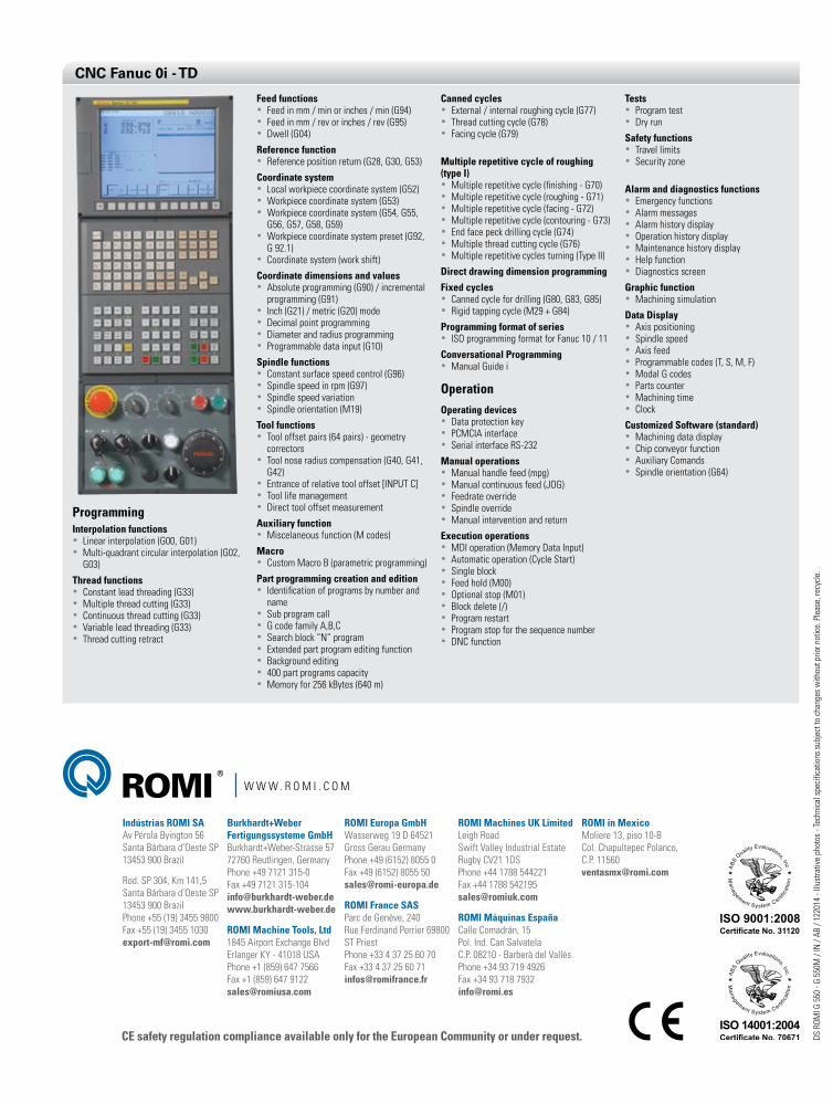
ProgrammingInterpolation functions• linear interpolation (G00, G01) • Multi-quadrant circular interpolation (G02,
G03)
Thread functions• Constant lead threading (G33) • Multiple thread cutting (G33)• Continuous thread cutting (G33) • Variable lead threading (G33) • Thread cutting retract
Feed functions• feed in mm / min or inches / min (G94)• feed in mm / rev or inches / rev (G95)• Dwell (G04)
Reference function• Reference position return (G28, G30, G53)
Coordinate system• local workpiece coordinate system (G52)• Workpiece coordinate system (G53) • Workpiece coordinate system (G54, G55,
G56, G57, G58, G59)• Workpiece coordinate system preset (G92,
G 92.1) • Coordinate system (work shift)
Coordinate dimensions and values• absolute programming (G90) / incremental
programming (G91)• Inch (G21) / metric (G20) mode • Decimal point programming • Diameter and radius programming• programmable data input (G10)
Spindle functions• Constant surface speed control (G96)• Spindle speed in rpm (G97) • Spindle speed variation • Spindle orientation (M19)
Tool functions• Tool offset pairs (64 pairs) - geometry
correctors• Tool nose radius compensation (G40, G41,
G42) • entrance of relative tool offset [InpuT C] • Tool life management • Direct tool offset measurement
Auxiliary function• Miscelaneous function (M codes)
Macro• Custom Macro B (parametric programming)
Part programming creation and edition• Identification of programs by number and
name • Sub program call • G code family a,B,C • Search block “n” program • extended part program editing function • Background editing • 400 part programs capacity• Memory for 256 kBytes (640 m)
Canned cycles• external / internal roughing cycle (G77) • Thread cutting cycle (G78) • facing cycle (G79)
Multiple repetitive cycle of roughing (type I)• Multiple repetitive cycle (finishing - G70) • Multiple repetitive cycle (roughing - G71) • Multiple repetitive cycle (facing - G72)• Multiple repetitive cycle (contouring - G73)• end face peck drilling cycle (G74)• Multiple thread cutting cycle (G76)• Multiple repetitive cycles turning (Type II)
Direct drawing dimension programming
Fixed cycles• Canned cycle for drilling (G80, G83, G85) • Rigid tapping cycle (M29 + G84)
Programming format of series• ISO programming format for fanuc 10 / 11
Conversational Programming• Manual Guide i
OperationOperating devices• Data protection key • pCMCIa interface • Serial interface RS-232
Manual operations• Manual handle feed (mpg) • Manual continuous feed (JOG) • feedrate override • Spindle override • Manual intervention and return
Execution operations• MDI operation (Memory Data Input) • automatic operation (Cycle Start) • Single block • feed hold (M00) • Optional stop (M01) • Block delete (/) • program restart • program stop for the sequence number• DnC function
Tests• program test • Dry run
Safety functions• Travel limits • Security zone
Alarm and diagnostics functions• emergency functions • alarm messages • alarm history display • Operation history display • Maintenance history display • help function • Diagnostics screen
Graphic function• Machining simulation
Data Display• axis positioning • Spindle speed • axis feed • programmable codes (T, S, M, f) • Modal G codes • parts counter • Machining time • Clock
Customized Software (standard)• Machining data display • Chip conveyor function • auxiliary Comands• Spindle orientation (G64)
CNC Fanuc 0i - TD
CE safety regulation compliance available only for the European Community or under request. DS R
OMI G
550
- G
550M
/ In
/ aB
/ 12
2014
- lll
ustra
tive
phot
os -
Tech
nica
l spe
cific
atio
ns s
ubje
ct to
cha
nges
with
out p
rior n
otic
e. p
leas
e, re
cycl
e.
W W W . R O M I . C O M
Indústrias ROMI SA av pérola Byington 56 Santa Bárbara d’Oeste Sp 13453 900 Brazil
Rod. Sp 304, Km 141,5 Santa Bárbara d’Oeste Sp 13453 900 Brazil phone +55 (19) 3455 9800 fax +55 (19) 3455 1030 [email protected]
ROMI Europa GmbH Wasserweg 19 D 64521 Gross Gerau Germany phone +49 (6152) 8055 0 fax +49 (6152) 8055 50 [email protected]
ROMI France SAS parc de Genève, 240 Rue ferdinand perrier 69800 ST priest phone +33 4 37 25 60 70 fax +33 4 37 25 60 71 [email protected]
Burkhardt+Weber Fertigungssysteme GmbH Burkhardt+Weber-Strasse 57 72760 Reutlingen, Germany phone +49 7121 315-0 fax +49 7121 315-104 [email protected] www.burkhardt-weber.de
ROMI Machine Tools, Ltd 1845 airport exchange Blvd erlanger KY - 41018 uSa phone +1 (859) 647 7566 fax +1 (859) 647 9122 [email protected]
ROMI Machines UK Limited leigh Road Swift Valley Industrial estate Rugby CV21 1DS phone +44 1788 544221 fax +44 1788 542195 [email protected]
ROMI Máquinas España Calle Comadrán, 15 pol. Ind. Can Salvatela C.p. 08210 - Barberà del Vallès phone +34 93 719 4926 fax +34 93 718 7932 [email protected]
ROMI in Mexico Moliere 13, piso 10-B Col. Chapultepec polanco, C.p. 11560 [email protected]


