36
Rotary Tables

Rotary Tables

Note:The technical data in this catalog may be changed without prior notice.

3TM-05-1-EN-1704-K
Motors, Drives & Accessories Rotary Tables
Directly-driven rotary tables from HIWIN have a backlash- free and very rigid design, making them highly versatile. The compact design makes the tables easy to integrate and allows for a space-saving setup. Various diameters and heights simplify the process of selecting the right rotary table. On request, the rotary tables are also supplied as a complete system with drive.

4
Rotary TablesContents
5TM-05-1-EN-1704-K
Contents
1 Product overview ............................................................................................................................................................7
2 Sample applications .......................................................................................................................................................82.1 HIWIN rotary tables optimise transport processes 82.2 HIWIN rotary table in glass plate handling 8
3 HIWIN rotary tables TMS .................................................................................................................................................93.1 Characteristics of the TMS rotary tables 93.2 Order code for TMS rotary tables 93.3 Technical data for TMS 103.3.1 Technical data for TMS0 103.3.2 Technical data for TMS1 123.3.3 Technical data for TMS3 143.3.4 Technical data for TMS7 18
4 HIWIN rotary tables TMB ............................................................................................................................................... 224.1 Characteristics of the TMB rotary tables 224.2 Order code for TMB rotary tables 224.3 Technical data for TMB0 23
5 HIWIN rotary tables TMN .............................................................................................................................................. 255.1 Characteristics of the TMN rotary tables 255.2 Order code for TMN rotary tables 255.3 Technical data for TMN 265.3.1 Technical data for TMN42 265.3.2 Technical data for TMN71 285.3.3 Technical data for TMN93 30
6 HIWIN rotary tables TMA ............................................................................................................................................... 326.1 Characteristics of the TMA rotary tables 326.2 Order code for TMA rotary tables 326.3 Technical data for TMA32 32

6
Rotary TablesProduct overview

7TM-05-1-EN-1704-K
1. Product overview
HIWIN rotary tables TMS Page 9
Standard series Torques up to 450 Nm Integrated rotary encoder Outer diameter 110 – 300 mm With pneumatic clamping as an option
HIWIN rotary tables TMB Page 22
Compact design Torques up to 6.4 Nm Outer diameter 65 mm Integrated rotary encoder
HIWIN rotary tables TMN Page 25
Extremely flat design Torques up to 39.6 Nm Outer diameter 118 – 230 mm Integrated rotary encoder
HIWIN rotary tables TMA Page 32
Air bearings Highest accuracy and synchronism Integrated rotary encoder
8
Rotary TablesSample applications, HIWIN rotary tables TMS
2. Sample applications
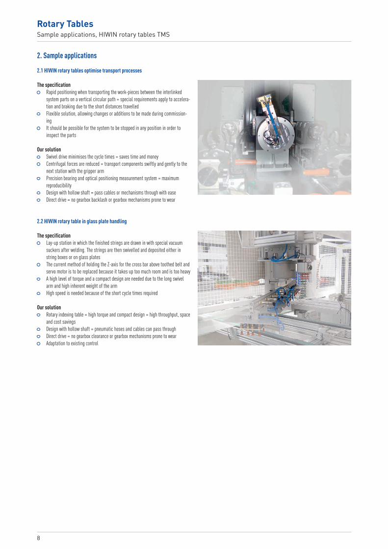
2.1 HIWIN rotary tables optimise transport processes
The specification Rapid positioning when transporting the work-pieces between the interlinked
system parts on a vertical circular path = special requirements apply to accelera-tion and braking due to the short distances travelled
Flexible solution, allowing changes or additions to be made during commission-ing
It should be possible for the system to be stopped in any position in order to inspect the parts
Our solution Swivel drive minimises the cycle times = saves time and money Centrifugal forces are reduced = transport components swiftly and gently to the
next station with the gripper arm Precision bearing and optical positioning measurement system = maximum
reproducibility Design with hollow shaft = pass cables or mechanisms through with ease Direct drive = no gearbox backlash or gearbox mechanisms prone to wear
2.2 HIWIN rotary table in glass plate handling
The specification Lay-up station in which the finished strings are drawn in with special vacuum
suckers after welding. The strings are then swivelled and deposited either in string boxes or on glass plates
The current method of holding the Z-axis for the cross bar above toothed belt and servo motor is to be replaced because it takes up too much room and is too heavy
A high level of torque and a compact design are needed due to the long swivel arm and high inherent weight of the arm
High speed is needed because of the short cycle times required
Our solution Rotary indexing table = high torque and compact design = high throughput, space
and cost savings Design with hollow shaft = pneumatic hoses and cables can pass through Direct drive = no gearbox clearance or gearbox mechanisms prone to wear Adaptation to existing control

9TM-05-1-EN-1704-K
3. HIWIN rotary tables TMS
Torque motor
Outer diameter [mm]:0: 1101: 1503: 2007: 300
Rotor height [mm]:2: 203: 304: 406: 607: 708: 80C: 120
Special equipment:0: NoneC: Customer specific
Protection class 1):0: IP401: IP65
F: Flange version 1)
Winding variant 1):None: standard windingL: For high rotary speed
Clamping element 1):0: NoneP: Pneumatic
Positioning measurement system:C: Optical, absolute (EnDat)D: Optical, incremental
Type:S: Rotary table complete with
crossed roller bearing
TM S 3 4 L D 0 0 F C
3.1 Characteristics of the TMS rotary tablesTMS rotary tables are directly driven rotary tables and do not therefore have a gearbox. The extremely rigid connection between the motor and load, coupled with a high-quality servo drive controller, ensures outstanding acceleration capabilities and movement with good uniformity. Due to the hollow shaft design, TMS rotary tables are especially well suited to automation tasks. Media, cable systems or mechanisms can pass through with ease.
Key features: Backlash-free and extremely dynamic Brush-less and high-torque Integrated optical rotary encoder With pneumatic clamping as an option P65 as an option Flange version as an option Absolute positioning measurement system as an option (EnDat 2.2, Siemens
DRIVE-CLiQ, Sick HIPERFACE, Fanuc or Mitsubishi interface)
Typical applications: Automation technology Pick-and-place machines
3.2 Order code for TMS rotary tables
1) Options depend on the series; see technical data

10
Rotary TablesHIWIN rotary tables TMS
3.3 Technical data for TMS
3.3.1 Technical data for TMS0
Torque-speed curves (DC bus voltage: 560 VDC)
04002000 600 800 1,000
46
2
81012
Torqu
e [N
m]
Speed [rpm]
04002000 600 800 1,000
10
15
5
20
25
Torqu
e [Nm
]
Speed [rpm]
TMS03 TMS07TpTc
TpTc
Table 3.1 Technical data for TMS0 HIWIN rotary tables
Symbol Unit TMS03 TMS07Technical data of rotary tablePeak torque (for 1 sec.) Tp Nm 9.3 18.6Continuous torque Tc Nm 3.1 6.2Stall torque Ts Nm 2.17 4.34Inertia of rotating parts J kgm2 0.003 0.006Weight Mm kg 4 7Max. axial load Fa N 3,700Max. radial load Fr N 820Max. moment of tilt Mk Nm 40Nominal speed (at 400 VAC, 30 % duty cycle) n 1/min 700Position accuracy arc sec ± 45/± 10 2)
Repeating accuracy arc sec ± 3Radial run-out mm 0.03 (optional 0.015)Axial run-out mm 0.03 (optional 0.005)Height H mm 117.5 150Protection class IP40Technical data of motorPeak current (for 1 sec.) Ip Aeff 6.0Continuous current Ic Aeff 2.0Motor constant Km Nm/√ W 0.5 0,8Resistance 1) R25 Ω 7.1 11.1Inductance 1) L mH 15.2 22.2Electrical time constant Te ms 2.1 2.0Torque constant Kt Nm/Aeff 1.55 3.10Back emf constant Ku Veff/(rad/s) 0.82 1.70Number of poles 2p 10Thermal resistance Rth °C/W 1.76 1.13Thermal time constant Tth s 1,930 1,980Thermal sensor PTC SNM 100Max. DC Bus V 600
All the specifications in the table (except dimensions) are in ± 10 % of tolerance at 25 °C ambient temperature1) Line-to-line2) With error mapping
Encoder type D specifications (optical, incremental) 5,026 lines/cycle Index mark Signal output sin/cos 1 VPP
11TM-05-1-EN-1704-K
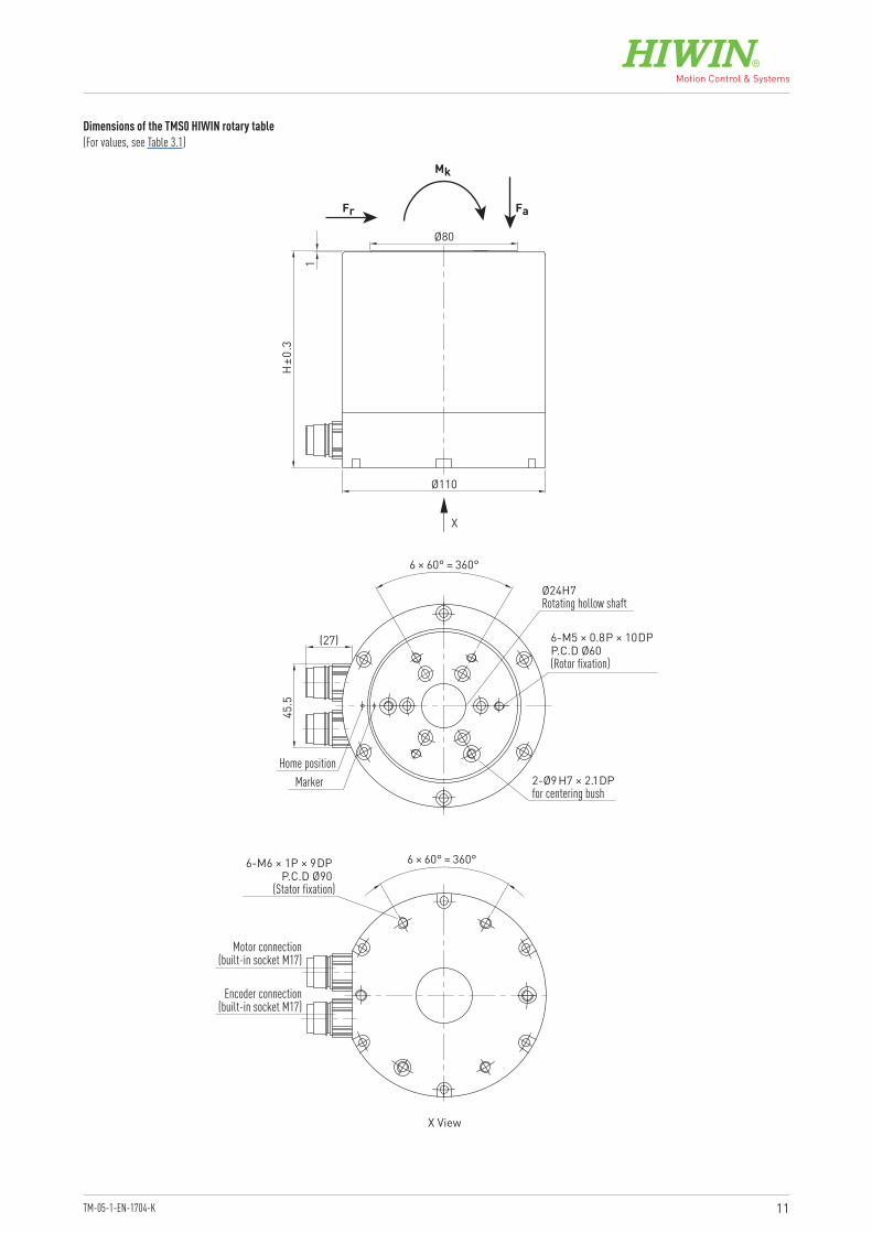
Dimensions of the TMS0 HIWIN rotary table(For values, see Table 3.1)
Ø110
Ø80
X View
45.5
(27) 6-M5 × 0.8P × 10DPP.C.D Ø60 (Rotor fixation)
H±0
.3
1
6 × 60° = 360°
6-M6 × 1P × 9DP P.C.D Ø90
(Stator fixation)
X
Motor connection(built-in socket M17)
Encoder connection(built-in socket M17)
Ø24H7Rotating hollow shaft
6 × 60° = 360°
2-Ø9H7 × 2.1DP for centering bush
Fr Fa
Mk
MarkerHome position

12
Rotary TablesHIWIN rotary tables TMS
3.3.2 Technical data for TMS1
Torque-speed curves (DC bus voltage: 560 VDC)
04002000 600 800
69
3
121518
Torqu
e [Nm
]
Speed [rpm]
04002000 600 800
1015
5
2025303540
Torqu
e [Nm
]Speed [rpm]
TpTc
TpTc
04002000 600 800
2030
10
4050607080
Torqu
e [Nm
]
Speed [rpm]
TpTc
TMS18
TMS16
TMS14TMS12
Table 3.2 Technical data for TMS1 HIWIN rotary tables
Symbol Unit TMS12 TMS14 TMS16 TMS18Technical data of rotary tablePeak torque (for 1 sec.) Tp Nm 15 30 45 60Continuous torque Tc Nm 5 10 15 20Stall torque Ts Nm 3.5 7 10,5 14Inertia of rotating parts J kgm2 0.006 0.0065 0.007 0.0075Weight Mm kg 5.7 7 8.3 9.5Max. axial load Fa N 3,700Max. radial load Fr N 1,700Max. moment of tilt Mk Nm 60Nominal speed (at 400 VAC, 30 % duty cycle) n 1/min 600 500Position accuracy arc sec ± 45/± 10 2)
Repeating accuracy arc sec ± 3Radial run-out mm 0.03 (optional 0.015)Axial run-out mm 0.03 (optional 0.005)Height H mm 100 120 140 160Protection class IP40Technical data of motorPeak current (for 1 sec.) Ip Aeff 12Continuous current Ic Aeff 4Motor constant Km Nm/√ W 0.6 1.0 1.3 1.6Resistance 1) R25 Ω 2.6 3.9 5.2 6.5Inductance 1) L mH 8.2 14.0 20.0 26.0Electrical time constant Te ms 3.2 3.6 3.8 4.0Torque constant Kt Nm/Aeff 1.25 2.50 3.75 5.00Back emf constant Ku Veff/(rad/s) 0.6 1.2 1.8 2.4Number of poles 2p 22Thermal resistance Rth °C/W 1.76 0.80 0.60 0.48Thermal time constant Tth s 2,210 2,290 2,460 2,520Thermal sensor PTC SNM 100Max. DC Bus V 600
All the specifications in the table (except dimensions) are in ± 10 % of tolerance at 25 °C ambient temperature1) Line-to-line2) With error mapping
Encoder type D specifications (optical, incremental) 7,226 lines/cycle Index mark Signal output sin/cos 1 VPP

13TM-05-1-EN-1704-K
Dimensions of the TMS1 HIWIN rotary table(For values, see Table 3.2)
2-Ø5H7 × 7DPP.C.D Ø48
Ø150
Ø99
Fr Fa
Mk
H±0
.3
1
(27)
45.5
6-M6 × 1P × 9DPP.C.D Ø60 (Rotor fixation)
Ø35 H7Rotating hollow shaft
6 × 60°=360°
2-Ø9H7 × 2.1DP for centering bush
X View
8-M6 × 1P × 12DPP.C.D Ø142 (Stator fixation)
8 × 45°=360°
MarkerHome position
X
2-Ø5H7 × 7DPP.C.D Ø142
Motor connection(built-in socket M17)
Encoder connection(built-in socket M17)

14
Rotary TablesHIWIN rotary tables TMS
3.3.3 Technical data for TMS3
Torque-speed curves (DC bus voltage: 560 VDC)
04002000 600 800 1,000
10
2015
5
253035
Torqu
e [Nm
]
Speed [rpm]
04002000 600 1,000800
80
120
40
160
200
Torqu
e [Nm
]Speed [rpm]
TpTc
TpTc
04002000 600 1,000800
80
120
40
160
200
Torqu
e [Nm
]
Speed [rpm]
TpTcTMS32
TMS3C
TMS38
TMS34
TMS3CL
TMS38L
TMS34L
Table 3.3 Technical data for HIWIN rotary tables TMS3
Symbol Unit TMS32 TMS34 TMS34L TMS38 TMS38L TMS3C TMS3CLTechnical data of rotary tablePeak torque (for 1 sec.) Tp Nm 30 60 120 180Continuous torque Tc Nm 10 20 40 60Stall torque Ts Nm 7 14 28 42Inertia of rotating parts J kgm2 0.014 0.020 0.026 0.035Weight Mm kg 15 21 26 32Max. axial load Fa N 8,000Max. radial load Fr N 6,500Max. moment of tilt Mk Nm 240Nominal speed (at 400 VAC, 30 % duty cycle) n 1/min 700 700 700 450 700 300 600Position accuracy arc sec ± 25/± 10 2)
Repeating accuracy arc sec ± 2.5Radial run-out mm 0.05Axial run-out mm 0.05 (optional 0,01)Height H mm 130 150 190 230Protection class IP40 IP40 (optional IP65)Technical data of motorPeak current (for 1 sec.) Ip Aeff 10.2 10.2 20.4 10.2 20.4 10.2 20.4Continuous current Ic Aeff 3.4 3.4 6.8 3.4 6.8 3.4 6.8Motor constant Km Nm/√ W 1.1 1.8 2.8 3.6 3.5Resistance 1) R25 Ω 5 7.5 1.9 12 3 17.1 4.3Inductance 1) L mH 20.6 34.60 8.7 53.6 16.3 84.4 25.3Electrical time constant Te ms 4.1 4.6 4.6 4.5 5.4 4.9 5.9Torque constant Kt Nm/Aeff 3 6 3 12 6 18 9Back emf constant Ku Veff/(rad/s) 1.5 3 1.5 6 3 9 4.5Number of poles 2p 22Thermal resistance Rth °C/W 1.1 0.73 0.46 0.32Thermal time constant Tth s 1,980 2,020 2,130 2,170Thermal sensor PTC SNM 120Max. DC Bus V 600
All the specifications in the table (except dimensions) are in ± 10 % of tolerance at 25 °C ambient temperature1) Line-to-line2) With error mapping
15TM-05-1-EN-1704-K
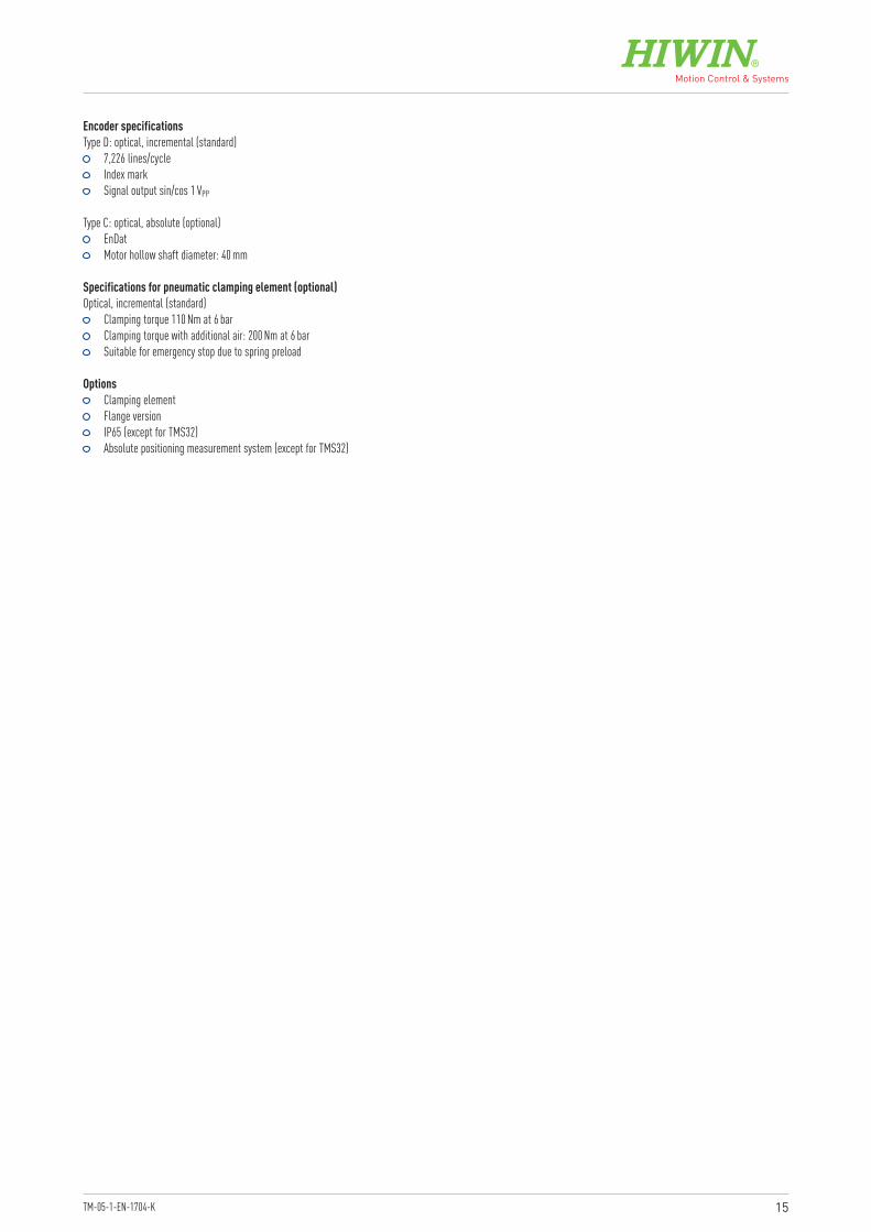
Options Clamping element Flange version IP65 (except for TMS32) Absolute positioning measurement system (except for TMS32)
Encoder specificationsType D: optical, incremental (standard)
7,226 lines/cycle Index mark Signal output sin/cos 1 VPP
Type C: optical, absolute (optional) EnDat Motor hollow shaft diameter: 40 mm
Specifications for pneumatic clamping element (optional)Optical, incremental (standard)
Clamping torque 110 Nm at 6 bar Clamping torque with additional air: 200 Nm at 6 bar Suitable for emergency stop due to spring preload

16
Rotary TablesHIWIN rotary tables TMS
Dimensions of the TMS3 HIWIN rotary table(For values, see Table 3.3)
Rotating hollow shaft
H
Encoder connection(built-in socket M17)
9×30° (=270°)
Ø180
X View
Connecting thread10×M6 × 9DP
Fr Fa
Mk
Motor connection(built-in socket M17)
X
Ø12H7 × 2.1DPfor centering bush
Ø12H7 × 2.1DPfor centering bush
Ø12 H7 × 2.1DPfor centering bush
Ø12 H7 × 2.1DPfor centering bush
Connecting thread8×M6 × 9DP
50
Ø 60
H7
Ø 12
0
Ø 20
0
Marker
Home position
8×45° (= 360°)
135°
17TM-05-1-EN-1704-K
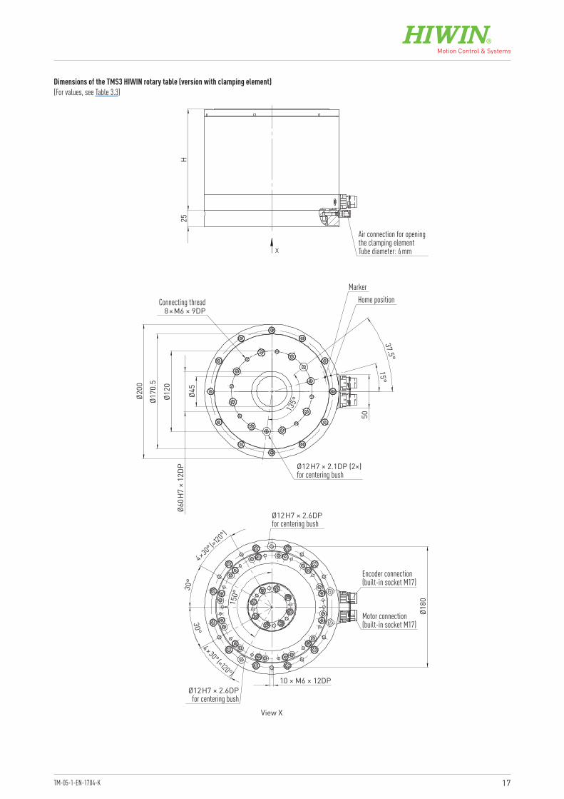
Dimensions of the TMS3 HIWIN rotary table (version with clamping element)(For values, see Table 3.3)
Air connection for opening the clamping element Tube diameter: 6 mm
MarkerHome position
H25
Connecting thread8×M6 × 9DP
Ø12H7 × 2.1DP (2×)for centering bush
Ø12H7 × 2.6DPfor centering bush
Ø12H7 × 2.6DPfor centering bush
10 × M6 × 12DP
4×30° (=120°)
30°
30°
150°
Ø180
37.5°15°
135°
50
Ø200
Ø45
Ø170
.5
Ø120
Ø60H
7 ×
12DP
View X
Encoder connection(built-in socket M17)
Motor connection(built-in socket M17)
4×30° (=120°)
18
Rotary TablesHIWIN rotary tables TMS
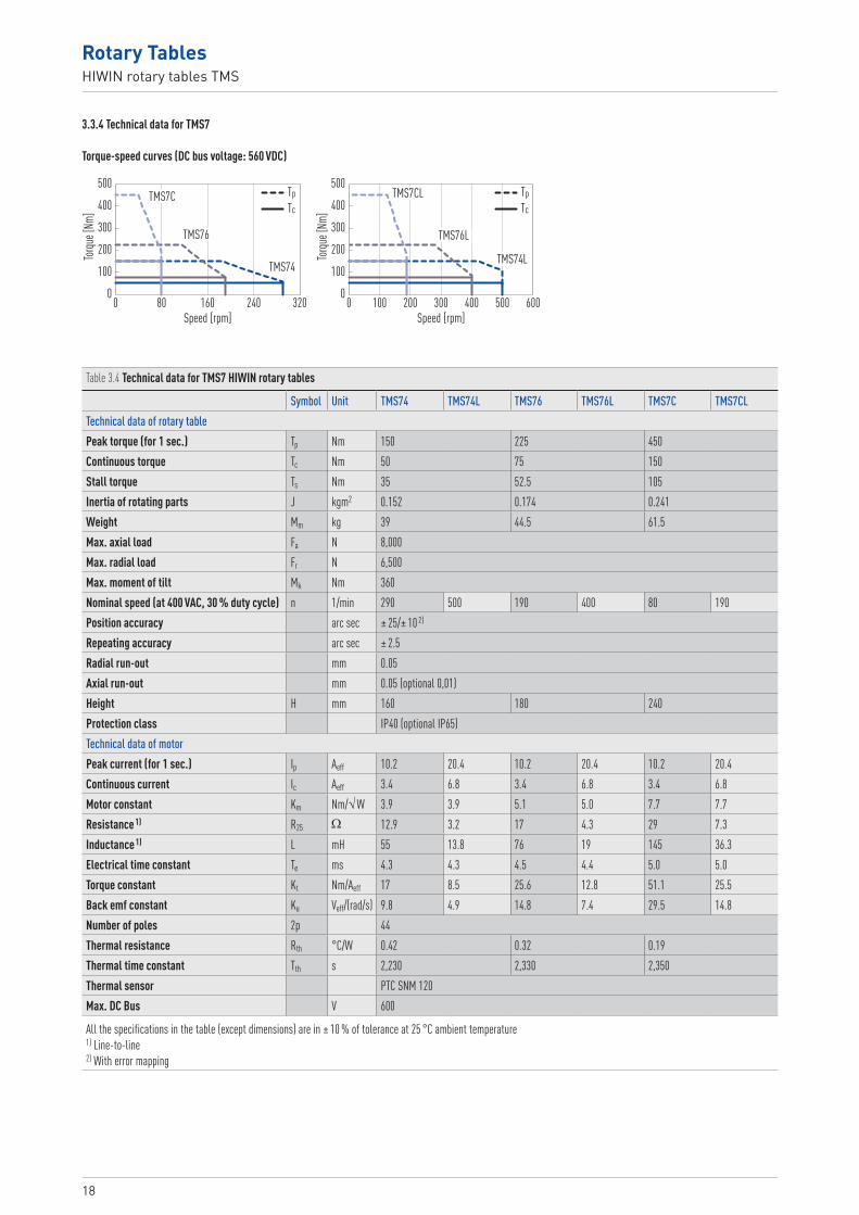
3.3.4 Technical data for TMS7
Torque-speed curves (DC bus voltage: 560 VDC)
0800 160 240 320
200
300
100
400
500
Torqu
e [Nm
]
Speed [rpm]
0300100 2000 400 600500
200
300
100
400
500
Torqu
e [Nm
]Speed [rpm]
TpTc
TpTc
TMS7C
TMS76
TMS74
TMS7CL
TMS76L
TMS74L
Table 3.4 Technical data for TMS7 HIWIN rotary tables
Symbol Unit TMS74 TMS74L TMS76 TMS76L TMS7C TMS7CLTechnical data of rotary tablePeak torque (for 1 sec.) Tp Nm 150 225 450Continuous torque Tc Nm 50 75 150Stall torque Ts Nm 35 52.5 105Inertia of rotating parts J kgm2 0.152 0.174 0.241Weight Mm kg 39 44.5 61.5Max. axial load Fa N 8,000Max. radial load Fr N 6,500Max. moment of tilt Mk Nm 360Nominal speed (at 400 VAC, 30 % duty cycle) n 1/min 290 500 190 400 80 190Position accuracy arc sec ± 25/± 10 2)
Repeating accuracy arc sec ± 2.5Radial run-out mm 0.05Axial run-out mm 0.05 (optional 0,01)Height H mm 160 180 240Protection class IP40 (optional IP65)Technical data of motorPeak current (for 1 sec.) Ip Aeff 10.2 20.4 10.2 20.4 10.2 20.4Continuous current Ic Aeff 3.4 6.8 3.4 6.8 3.4 6.8Motor constant Km Nm/√ W 3.9 3.9 5.1 5.0 7.7 7.7Resistance 1) R25 Ω 12.9 3.2 17 4.3 29 7.3Inductance 1) L mH 55 13.8 76 19 145 36.3Electrical time constant Te ms 4.3 4.3 4.5 4.4 5.0 5.0Torque constant Kt Nm/Aeff 17 8.5 25.6 12.8 51.1 25.5Back emf constant Ku Veff/(rad/s) 9.8 4.9 14.8 7.4 29.5 14.8Number of poles 2p 44Thermal resistance Rth °C/W 0.42 0.32 0.19Thermal time constant Tth s 2,230 2,330 2,350Thermal sensor PTC SNM 120Max. DC Bus V 600
All the specifications in the table (except dimensions) are in ± 10 % of tolerance at 25 °C ambient temperature1) Line-to-line2) With error mapping

19TM-05-1-EN-1704-K
Options Clamping element Flange version IP65 Absolute positioning measurement system
Encoder specificationsType D: optical, incremental (standard)
11,152 lines/cycle Index mark Signal output sin/cos 1 VPP
Type C: optical, absolute (optional) EnDat Motor hollow shaft diameter: 40 mm
Specifications for pneumatic clamping element (optional)Optical, incremental (standard)
Clamping torque 330 Nm at 6 bar Clamping torque with additional air: 580 Nm at 6 bar Suitable for emergency stop due to spring preload
20
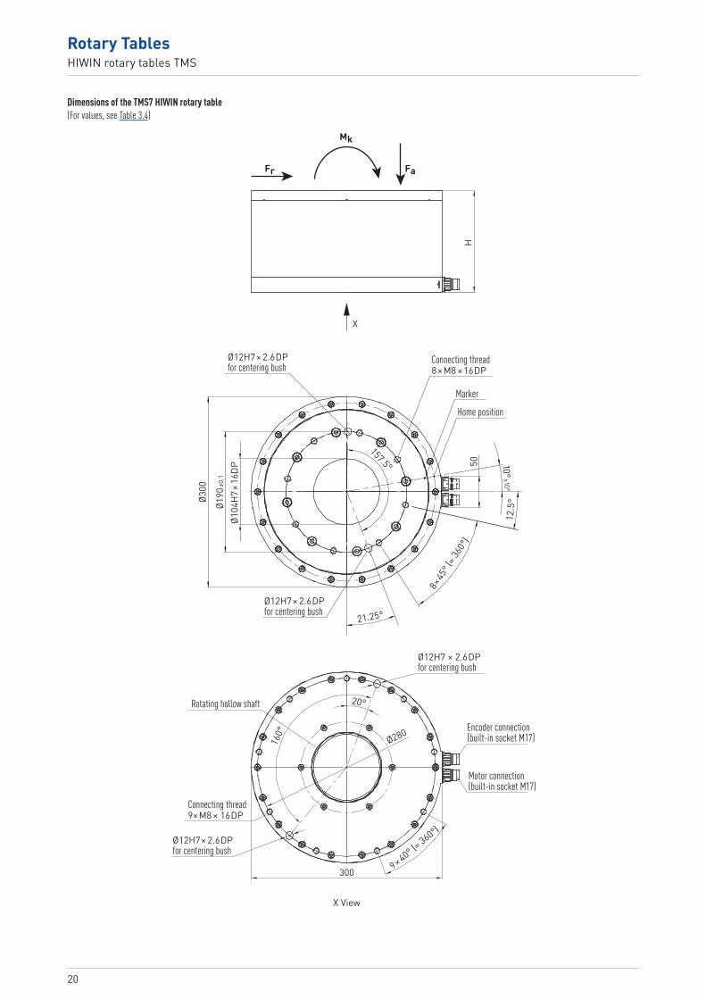
Rotary TablesHIWIN rotary tables TMS
Dimensions of the TMS7 HIWIN rotary table(For values, see Table 3.4)
Connecting thread9×M8 × 16DP
Fr Fa
Mk
X
X View
Rotating hollow shaft
H
Encoder connection(built-in socket M17)
Motor connection(built-in socket M17)
300 9× 40° (= 360°)
160°
20°
Ø280
Ø12H7 × 2.6DPfor centering bush
Ø12H7 × 2.6DPfor centering bush
Ø12H7 × 2.6DPfor centering bush
Marker
Home position
Connecting thread8×M8 × 16DP
Ø12H7 × 2.6DPfor centering bush
21.25°
157.5°
12.5
°
50 10°±10°
8× 45
° (= 3
60°)
Ø190
±0.1
Ø300
Ø104
H7 ×
16DP
21TM-05-1-EN-1704-K
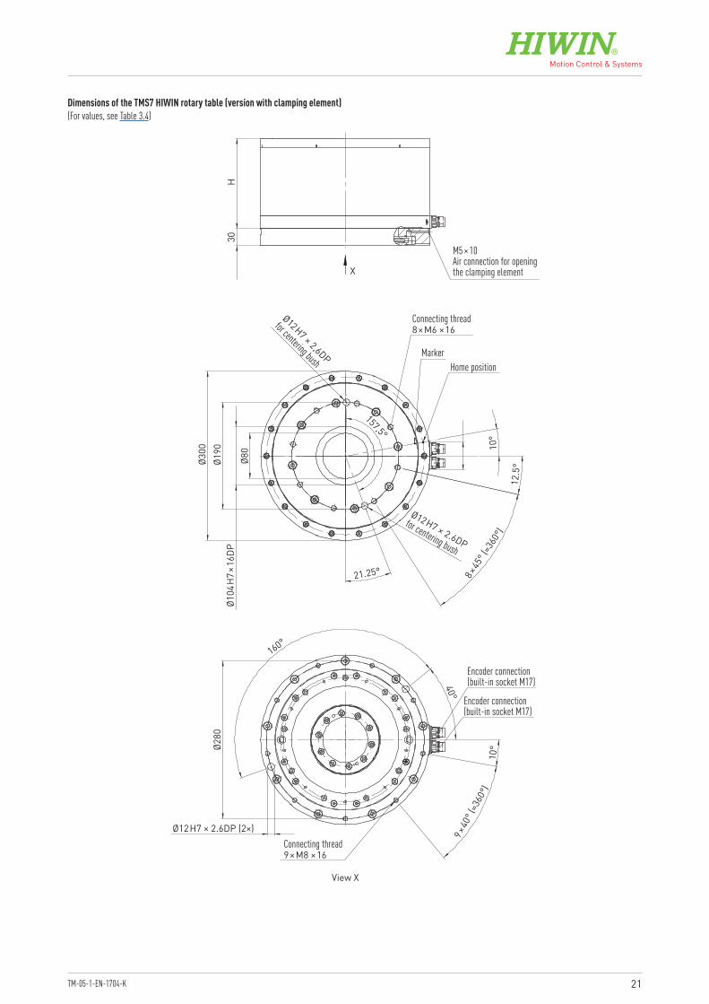
Dimensions of the TMS7 HIWIN rotary table (version with clamping element)(For values, see Table 3.4)
M5 × 10 Air connection for opening the clamping element
View X
H30
Ø300
Ø104
H7×
16DP
Ø190
Ø80
X
MarkerHome position
Ø12H7 × 2,6DP
for centering bush
Ø12H7 × 2.6DP
for centering bush
Connecting thread8×M6 × 16
Connecting thread9×M8 × 16
157,5°
10°
12.5
°
8×45
° (=3
60°)
9×40
° (=3
60°)
21.25°
Ø12H7 × 2.6DP (2×)
Ø280
160°
40°
10°
Encoder connection(built-in socket M17)
Encoder connection(built-in socket M17)
22
Rotary TablesHIWIN rotary tables TMB
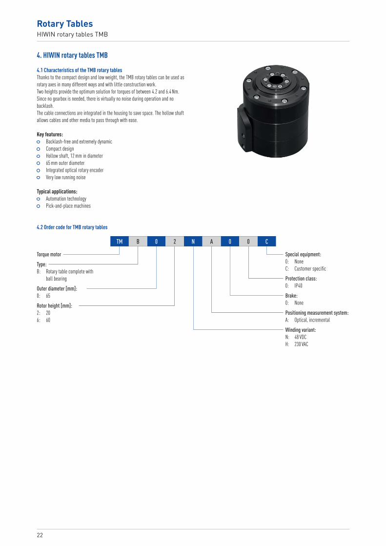
4. HIWIN rotary tables TMB
Torque motor
Outer diameter [mm]:0: 65
Rotor height [mm]:2: 206: 60
Special equipment:0: NoneC: Customer specific
Protection class:0: IP40
Winding variant:N: 48 VDCH: 230 VAC
Brake:0: None
Positioning measurement system:A: Optical, incremental
Type:B: Rotary table complete with
ball bearing
TM B 0 2 N A 0 0 C
4.1 Characteristics of the TMB rotary tablesThanks to the compact design and low weight, the TMB rotary tables can be used as rotary axes in many different ways and with little construction work.Two heights provide the optimum solution for torques of between 4.2 and 6.4 Nm. Since no gearbox is needed, there is virtually no noise during operation and no backlash.The cable connections are integrated in the housing to save space. The hollow shaft allows cables and other media to pass through with ease.
Key features: Backlash-free and extremely dynamic Compact design Hollow shaft, 12 mm in diameter 65 mm outer diameter Integrated optical rotary encoder Very low running noise
Typical applications: Automation technology Pick-and-place machines
4.2 Order code for TMB rotary tables

23TM-05-1-EN-1704-K
4.3 Technical data for TMB0
Torque-speed curves (DC bus voltage: TMB02N: 48 VDC; TMB02H: 320 VDC; TMB06H: 320 VDC)
0300 400100 2000 500 600 700 800
2.0
3.0
1.0
4.0
5.0
Torqu
e [Nm
]Speed [rpm]
TpTc
0300 400100 2000 500 600 700 800
2.0
3.0
1.0
4.0
5.0
Torqu
e [Nm
]
Speed [rpm]
TpTc
0400 500200 3001000 600 800700
2.03.04.0
1.0
5.06.07.0
Torqu
e [Nm
]
Speed [rpm]
TpTc
TMB02HTMB02N
TMB06H
Table 4.1 Technical data for TMB0 HIWIN rotary tables
Symbol Unit TMB02N-A00 TMB02H-A00 TMB06H-A00Technical data of rotary tablePeak torque (for 1 sec.) Tp Nm 3.0 2.56 6.4Continuous torque Tc Nm 0.9 0.59 1.4Stall torque Ts Nm 0.5 0.42 1Inertia of rotating parts J kgm2 3.5 × 10⁻⁵ 9.5 × 10⁻⁵
Weight Mm g 650 960 1,270Max. axial load Fa N 150Max. radial load Fr N 150Max. moment of tilt Mk Nm 4Nominal speed (30 % duty cycle) n 1/min 650 450 420Position accuracy arc sec 150Repeating accuracy arc sec 6Radial run-out mm 0.05Axial run-out mm 0.05Height H mm 72.6 115Protection class IP40Technical data of motorPeak current (for 1 sec.) Ip Aeff 23.1 5.5 9.7Continuous current Ic Aeff 6.9 1.26 2.0Motor constant Km Nm/√ W 0.11 0.10 0.2Resistance 1) R25 Ω 1.4 20.1 10.6Inductance 1) L mH 0.88 11.3 9.9Electrical time constant Te ms 0.63 0.56 0.93Torque constant Kt Nm/Aeff 0.13 0.46 0.66Back emf constant Ku Veff/(rad/s) 0.13 0.46 0.66Number of poles 2p 12Thermal resistance Rth °C/W 3.3 2.5Thermal sensor PTC SNM 125Max. DC Bus V 48 340
All the specifications in the table (except dimensions) are in ± 10 % of tolerance at 25 °C ambient temperature1) Line-to-line
Encoder specifications type A (optical, incremental) 2,048 lines/cycle Index mark Signal output sin/cos 1 VPP
24
Rotary TablesHIWIN rotary tables TMB, HIWIN rotary tables TMN
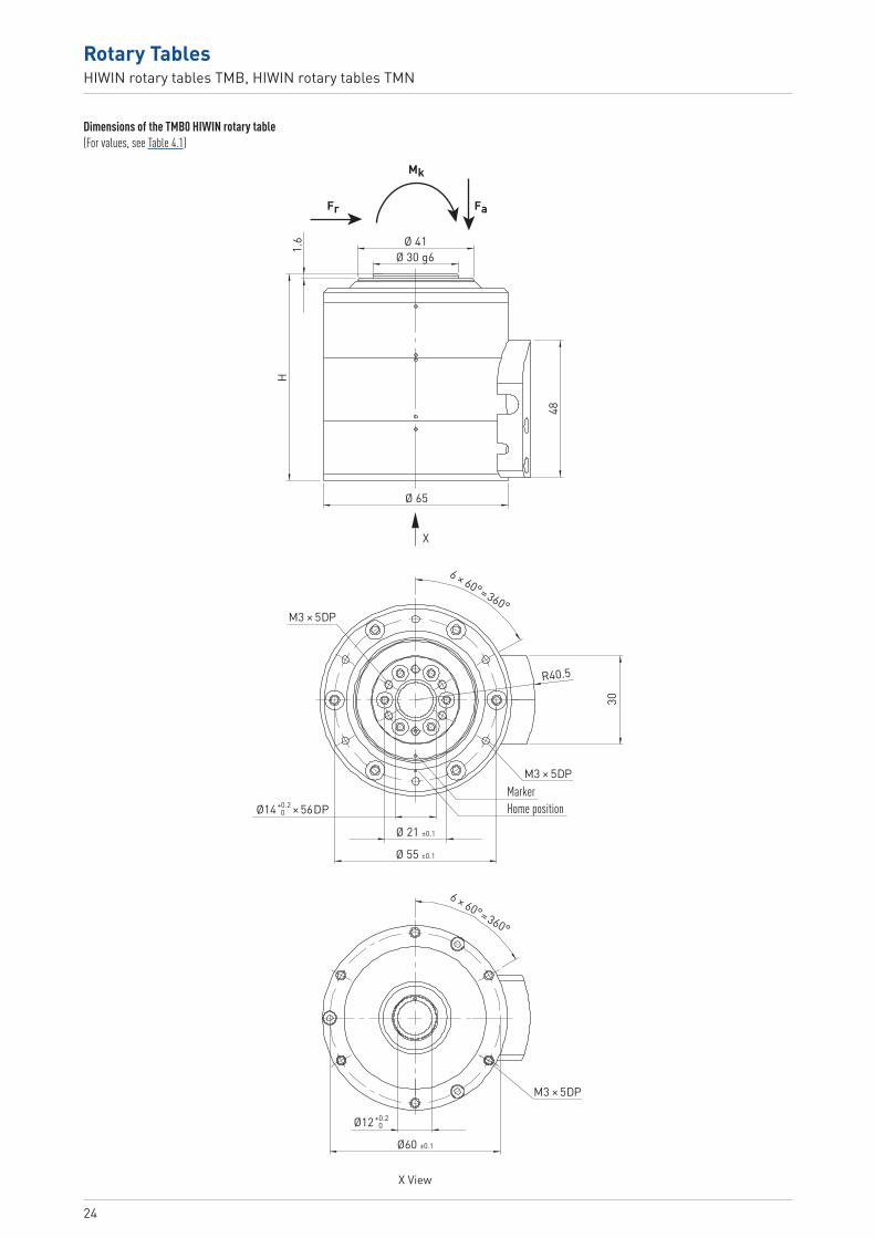
Dimensions of the TMB0 HIWIN rotary table(For values, see Table 4.1)
Fr Fa
X View
Mk
6 × 60°=360°
6 × 60°=360°
Ø 41
Ø 65
Ø12 +0.2 0
Ø 21 ±0.1
Ø 55 ±0.1
Ø60 ±0.1
30
R40.5
Ø 30 g6
1.6
H
48
MarkerHome position
X
Ø14 × 56DP+0.2 0
M3 × 5DP
M3 × 5DP
M3 × 5DP

25TM-05-1-EN-1704-K
5. HIWIN rotary tables TMN
Torque motor
Outer diameter [mm]:4: 1187: 1809: 230
Positioning measurement system:E: Encoder
Rotor height [mm]:1: 102: 203: 30
Type:N: Rotary table complete,
flat design
TM N 7 1 E
5.1 Characteristics of the TMN rotary tablesThe particularly flat and light precision rotary tables of the TMN series are suited to all applications in which high rigidity and accuracy are needed along with the smallest dimensions possible. Typical areas of use include the manufacture of LEDs, solar cells and semiconductors. The zero-maintenance TMN rotary tables use precision bearings and optical encoders to achieve very high positioning and repeat accuracy.
Key features: Backlash-free and extremely dynamic Extremely flat design Integrated rotary encoder
Typical applications: LED manufacture and testing Production of solar cells Manufacture of semiconductor components
5.2 Order code for TMN rotary tables

26
Rotary TablesHIWIN rotary tables TMN
5.3 Technical data for TMN
5.3.1 Technical data for TMN42
Torque-speed curves (DC bus voltage: 320/560 VDC)
04002000 600 800 1,000
2.0
3.0
1.0
4.0
5.0
Torqu
e [Nm
]
Speed [rpm]
TpTc
TMN42
Table 5.1 Technical data for TMN42 HIWIN rotary tables
Symbol Unit TMN42Technical data of rotary tablePeak torque (for 1 sec.) Tp Nm 4.2Continuous torque Tc Nm 1.4Stall torque Ts Nm 0.98Inertia of rotating parts J kgm2 0.003Weight Mm kg 2Max. axial load Fa N 600Max. radial load Fr N 600Max. moment of tilt Mk Nm 30Nominal speed (at 400 VAC) n 1/min 700Position accuracy arc sec ± 45Repeating accuracy arc sec ± 2.5Radial run-out mm 0.03Axial run-out mm 0.03Height H mm 45Protection class IP40Technical data of motorPeak current (for 1 sec.) Ip Aeff 4.5Continuous current Ic Aeff 1.5Motor constant Km Nm/√ W 0.4Resistance 1) R25 Ω 4.59Inductance 1) L mH 8.18Electrical time constant Te ms 1.78Torque constant Kt Nm/Aeff 0.97Back emf constant Ku Veff/(rad/s) 0.56Number of poles 2p 16Thermal resistance Rth °C/W 4.84Thermal time constant Tth s 1,170Thermal sensor PTC SNM 100Max. DC Bus V 600
All the specifications in the table (except dimensions) are in ± 10 % of tolerance at 25 °C ambient temperature1) Line-to-line
Encoder specifications (optical, incremental) 2,048 lines/cycle Index mark Signal output sin/cos 1 VPP
27TM-05-1-EN-1704-K
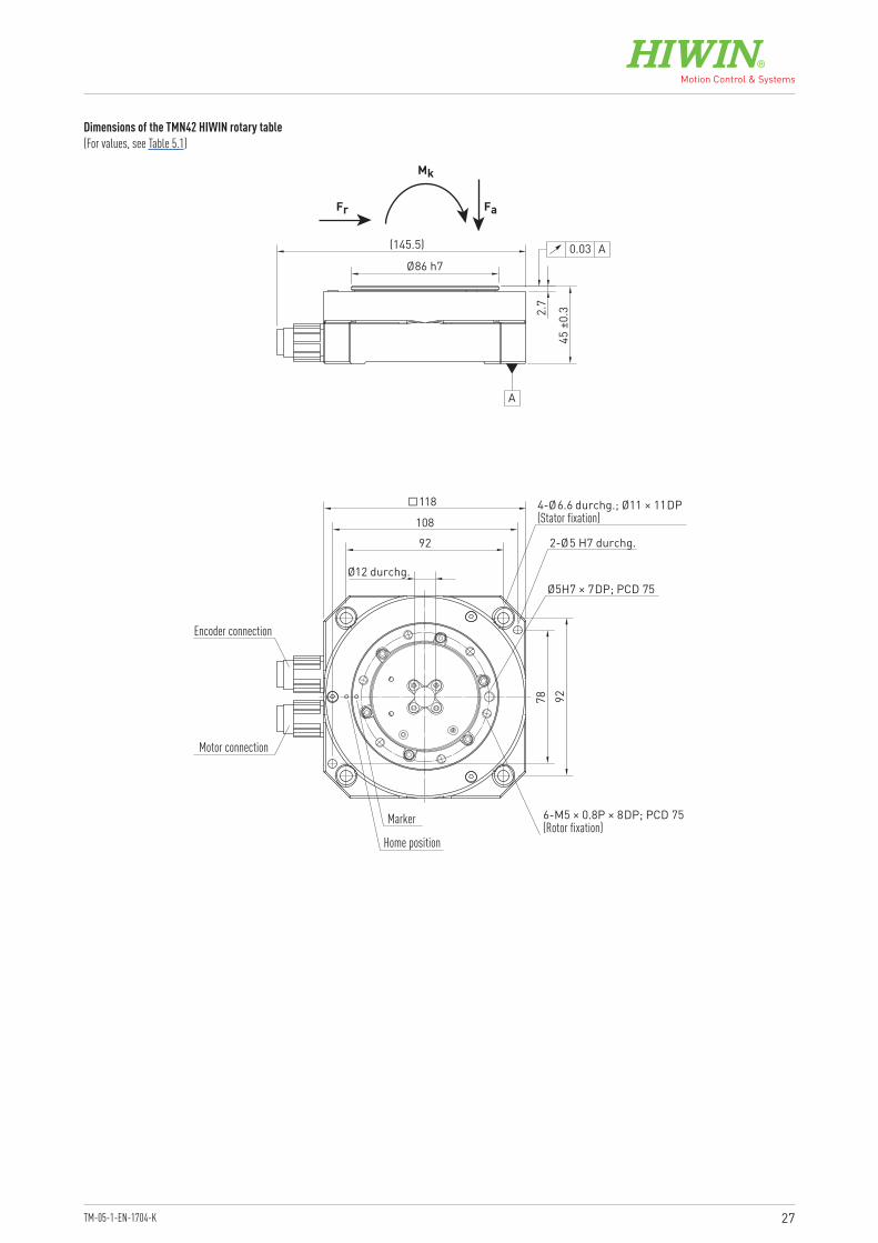
Dimensions of the TMN42 HIWIN rotary table(For values, see Table 5.1)
118
9278
108
Ø12 durchg.45
±0.32.
7
Ø86 h7
(145.5)
4-Ø6.6 durchg.; Ø11 × 11DP(Stator fixation)
2-Ø5 H7 durchg.
6-M5 × 0.8P × 8DP; PCD 75(Rotor fixation)
Ø5H7 × 7DP; PCD 75
92
Encoder connection
Motor connection
A
0.03 A
Marker
Home position
Fr Fa
Mk

28
Rotary TablesHIWIN rotary tables TMN
5.3.2 Technical data for TMN71
Torque-speed curves (DC bus voltage: 320/560 VDC)
04002000 600 800 1,000
68
42
1012
Torqu
e [Nm
]
Speed [rpm]
TpTc
TMN71
Table 5.2 Technical data for TMN71 HIWIN rotary tables
Symbol Unit TMN71Technical data of rotary tablePeak torque (for 1 sec.) Tp Nm 11.1Continuous torque Tc Nm 3.7Stall torque Ts Nm 2.59Inertia of rotating parts J kgm2 0.008Weight Mm kg 3.5Max. axial load Fa N 1,000Max. radial load Fr N 1,000Max. moment of tilt Mk Nm 50Nominal speed (at 400 VAC) n 1/min 600Position accuracy arc sec ± 45Repeating accuracy arc sec ± 2.5Radial run-out mm 0.03Axial run-out mm 0.03Height H mm 50Protection class IP40Technical data of motorPeak current (for 1 sec.) Ip Aeff 10.2Continuous current Ic Aeff 3.4Motor constant Km Nm/√ W 0.6Resistance 1) R25 Ω 2.22Inductance 1) L mH 9.02Electrical time constant Te ms 4.1Torque constant Kt Nm/Aeff 1.09Back emf constant Ku Veff/(rad/s) 0.63Number of poles 2p 16Thermal resistance Rth °C/W 1.95Thermal time constant Tth s 1,420Thermal sensor PTC SNM 100Max. DC Bus V 600
All the specifications in the table (except dimensions) are in ± 10 % of tolerance at 25 °C ambient temperature1) Line-to-line
Encoder specifications (optical, incremental) 2,048 lines/cycle Index mark Signal output sin/cos 1 VPP

29TM-05-1-EN-1704-K
Dimensions of the TMN71 HIWIN rotary table(For values, see Table 5.2)
160
50
146
120
45±0
.3140
140
(212)
A
0.03 A
4-Ø6.6 durchg.; Ø11 × 7DP (Stator fixation)
2-Ø6 H7 durchg.
Ø5 H7 × 7DP; PCD 160
Ø35 durchg.
Motor connection
Encoder connection
6-M5 × 0.8P × 8DP; PCD 160(Rotor fixation)
Ø150 h7(Ø180)
Fr Fa
Mk
MarkerHome position

30
Rotary TablesHIWIN rotary tables TMN
5.3.3 Technical data for TMN93
Torque-speed curves (DC bus voltage: 320/560 VDC)
05004003002001000 600 700 800
3035
2025
51015
4045
Torqu
e [Nm
]
Speed [rpm]
TpTc
TMN93
Table 5.3 Technical data for TMN93 HIWIN rotary tables
Symbol Unit TMN93Technical data of rotary tablePeak torque (for 1 sec.) Tp Nm 39.6Continuous torque Tc Nm 13.2Stall torque Ts Nm 9.24Inertia of rotating parts J kgm2 0.012Weight Mm kg 7.5Max. axial load Fa N 1,000Max. radial load Fr N 1,000Max. moment of tilt Mk Nm 50Nominal speed (at 400 VAC) n 1/min 500Position accuracy arc sec ± 45Repeating accuracy arc sec ± 2.5Radial run-out mm 0.03Axial run-out mm 0.03Height H mm 55Protection class IP40Technical data of motorPeak current (for 1 sec.) Ip Aeff 10.2Continuous current Ic Aeff 3.4Motor constant Km Nm/√ W 1.5Resistance 1) R25 Ω 4.3Inductance 1) L mH 23.2Electrical time constant Te ms 5.4Torque constant Kt Nm/Aeff 3.9Back emf constant Ku Veff/(rad/s) 2.25Number of poles 2p 22Thermal resistance Rth °C/W 1.01Thermal time constant Tth s 1,780Thermal sensor PTC SNM 100Max. DC Bus V 600
All the specifications in the table (except dimensions) are in ± 10 % of tolerance at 25 °C ambient temperature1) Line-to-line
Encoder specifications (optical, incremental) 3,600 lines/cycle Index mark Signal output sin/cos 1 VPP

31TM-05-1-EN-1704-K
Dimensions of the TMN93 HIWIN rotary table(For values, see Table 5.3)
2-Ø8H7 ( ) durchg.
(Ø230)
(142.5)
(47.
6)
Motor connection
Encoder connection
Home positionMarker
180 ±0.1200 ±0.05
75 ±0.0522.5°
45° TYP
Ø35
2423.351
.555
±0.
3
150
±0.0
5
180
±0.1
( 2
12)
Ø160 h7 ( ) 0–0.04
Ø5H7 ( ) × 7DP+0.012 0
+0.015 0
A
0.03 A
0.03 B
8-M5 × 0.8P × 10DP; PCD 150 ±0.1(Rotor fixation)
4-Ø15 × 14DP; Ø9 durchg.(Stator fixation)
Fr Fa
Mk

32
Rotary TablesHIWIN rotary tables TMA
6. HIWIN rotary tables TMA
Torque motor
Outer dimensions [mm]:3: 200 × 200
Rotor height [mm]:2: 20
Protection class:0: IP40
Brake:0: None
Positioning measurement system:A: Optical, incremental
Type:A: Rotary table complete with
air bearing
TM A 3 2 A 0 0
6.1 Characteristics of the TMA rotary tablesThe rotary tables of the TMA series with air bearings were developed especially for applications with high synchronism and precision. The running tolerances have been reduced to a minimum.The rotary table thereby achieves a positioning accuracy of 20 arcsec and a repeat accuracy of 2 arcsec.
Key features: Backlash-free and extremely dynamic Air bearings High accuracy and high synchronism Integrated optical rotary encoder
Typical applications: Measuring technology Test machines
6.2 Order code for TMA rotary tables
6.3 Technical data for TMA32
Torque-speed curve (DC bus voltage: 560 VDC)
02000 400 600 800 1,000 1,200
20
30
10
40
Torqu
e [Nm
]
Speed [rpm]
TpTc
TMA32
33TM-05-1-EN-1704-K
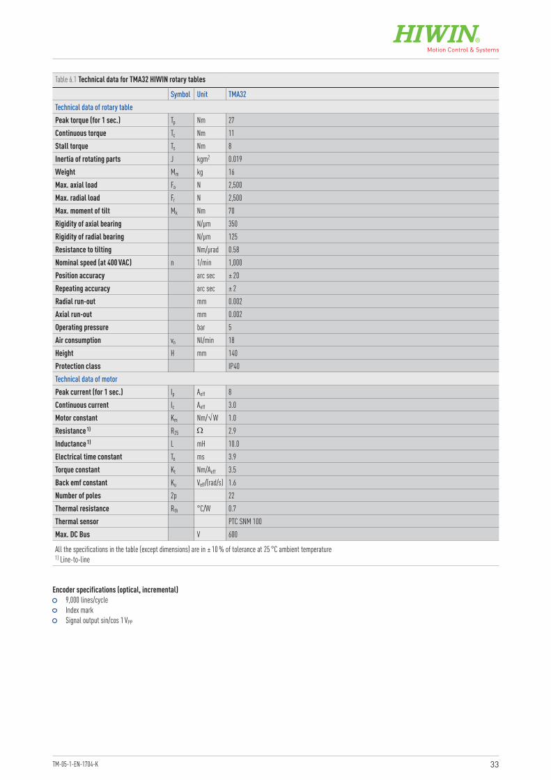
Encoder specifications (optical, incremental) 9,000 lines/cycle Index mark Signal output sin/cos 1 VPP
Table 6.1 Technical data for TMA32 HIWIN rotary tables
Symbol Unit TMA32Technical data of rotary tablePeak torque (for 1 sec.) Tp Nm 27Continuous torque Tc Nm 11Stall torque Ts Nm 8Inertia of rotating parts J kgm2 0.019Weight Mm kg 16Max. axial load Fa N 2,500Max. radial load Fr N 2,500Max. moment of tilt Mk Nm 70Rigidity of axial bearing N/µm 350Rigidity of radial bearing N/µm 125Resistance to tilting Nm/µrad 0.58Nominal speed (at 400 VAC) n 1/min 1,000Position accuracy arc sec ± 20Repeating accuracy arc sec ± 2Radial run-out mm 0.002Axial run-out mm 0.002Operating pressure bar 5Air consumption vn Nl/min 18Height H mm 140Protection class IP40Technical data of motorPeak current (for 1 sec.) Ip Aeff 8Continuous current Ic Aeff 3.0Motor constant Km Nm/√ W 1.0Resistance 1) R25 Ω 2.9Inductance 1) L mH 10.0Electrical time constant Te ms 3.9Torque constant Kt Nm/Aeff 3.5Back emf constant Ku Veff/(rad/s) 1.6Number of poles 2p 22Thermal resistance Rth °C/W 0.7Thermal sensor PTC SNM 100Max. DC Bus V 600
All the specifications in the table (except dimensions) are in ± 10 % of tolerance at 25 °C ambient temperature1) Line-to-line
34
Rotary TablesHIWIN rotary tables TMA
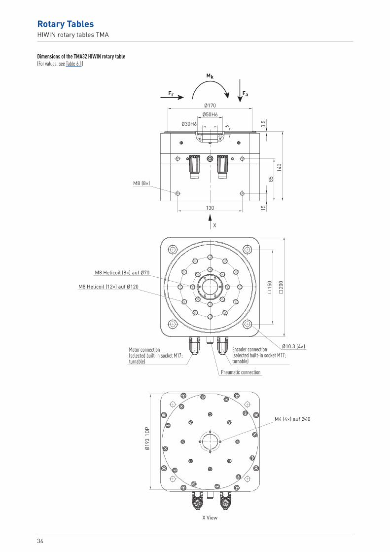
Dimensions of the TMA32 HIWIN rotary table(For values, see Table 6.1)
140
8515
3.5
6Ø30H6
Ø50H6Ø170
130
M8 (8×)
X View
M4 (4×) auf Ø40
150
200
M8 Helicoil (8×) auf Ø70
M8 Helicoil (12×) auf Ø120
Ø10.3 (4×)Encoder connection(selected built-in socket M17; turnable)
Pneumatic connection
Motor connection(selected built-in socket M17; turnable)
Fr Fa
Mk
X
Ø193
1DP

Linear Actuators
Linear Motor Components
Linear Axes
Ballscrews Linear Motor Systems
Rotary Tables
Robots
Linear Guideways
Drives & Servo Motors
Linear Axes
TM-05-1-EN-1704-K


