17
ROUTE PACKETS, NOT WIRES: ON-CHIP INTERCONNECTION NETWORKS Veronica Eyo Sharvari Joshi
ROUTE PACKETS, NOT WIRES: ON-CHIP INTERCONNECTION NETWORKSVeronica EyoSharvari Joshi
ON-CHIP INTERCONNECT NETWORK/ NOC The layered-stack approach to the design of
the on-chip intercore communications is called the Network-on-Chip (NOC) methodology
New approach to design the communication subsystem of a System-on-Chip.
Asynchronous clocking Networking theories and systematic
networking methods
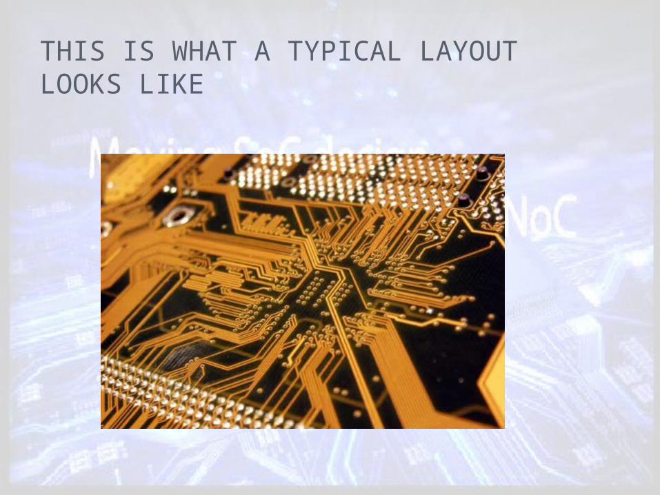
THIS IS WHAT A TYPICAL LAYOUT LOOKS LIKE

PROPOSAL Replace design-specific global on-chip wiring
with a general-purpose on-chip interconnection network.
Connect top level modules by dedicated wires connect them to a network that routes packet between them.

A SIMPLE ON-CHIP NETWORK 12mm x 12mm chip
in 0.1mm CMOS technology with an 0.5mm minimum wire pitch
network uses a 2-dimensional folded torus topology with the nodes 0-3 in each row cyclically connected in the order 0,2,3,1

INPUT PORTDATAGRAM INTERFACE TO EACH TILE
Start of new packet (head) Continuation of a packet (body) End of packet (tail) Idle cycle (idle) Logarithmically encodes the size of the data in the data field
from 0 (1 bit) to 8 (256 bits) Specifies which of eight virtual channels this packet may be
routed on A source route that specifies two bits for each hop (left, right,
straight, or extract). A signal from the network back to the client indicating that the
network is ready to accept the next flit on each virtual channel
TYPE2 Bits
SIZE4 Bits
VIRTUAL CHANNEL
8 BitsROUTE 16 Bits
READY8 Bits

OTHER RESOURCES Registers:
Used to reserve resources for particular virtual channels
Provide time-slot reservations for certain classes of traffic
Pre-scheduling provides guaranteed, predictable performance for latency-critical or jitter-critical applications

HIGHER LEVEL PROTOCOL ON SIMPLE INTERFACE Services that can be provided to network
clients: Memory read/write service A flow-controlled data stream A logical wire to the client Provide a translation from a destination node to
a route The logic to implement many higher-level
services on top of the simple network will be made readily available so it won’t have to be independently redesigned with each module

ROUTER ARCHITECTUREIs needed at each tile Consists of 5 input and
output controllers

PROS AND CONS Network takes up upto 6.6% of the total tile
area The area of the router is dominated by buffer
space The total buffer requirement is about 10^4 bits
along each edge of the tile Enables the use of fault tolerant wiring and
protocols A spare bit can be provided on each network link
and in each network buffer Network handles both pre-scheduled and
dynamic traffic Static traffic must share the network with
dynamic traffic
TOPOLOGIES TO UTILIZE THE ABUNDANT WIRING RESOURCES Method 1:
A wide (almost 300-bit) flit is sent broadside across router channels to use the maximum possible number of pins
Method 2: A folded torus topology can be employed Has twice the wire demand and twice the
bisection bandwidth of a mesh network Choice of a topology depends on many
factors
FLOW CONTROL METHODS TO REDUCE BUFFER COUNT Buffer space in an on-chip router directly
impacts the area overhead of the network Example network uses conventional virtual
channel flow control and uses a large amount of buffer space
Trade-off between buffer storage requirement and performance
NEED TO EXPLOIT STRUCTURED WIRING Well controlled electrical parameters of
wiring enable the use of high-performance circuits
Circuits can be used to boost the bandwidth of individual wires
Circuits can ease the overhead of buffers
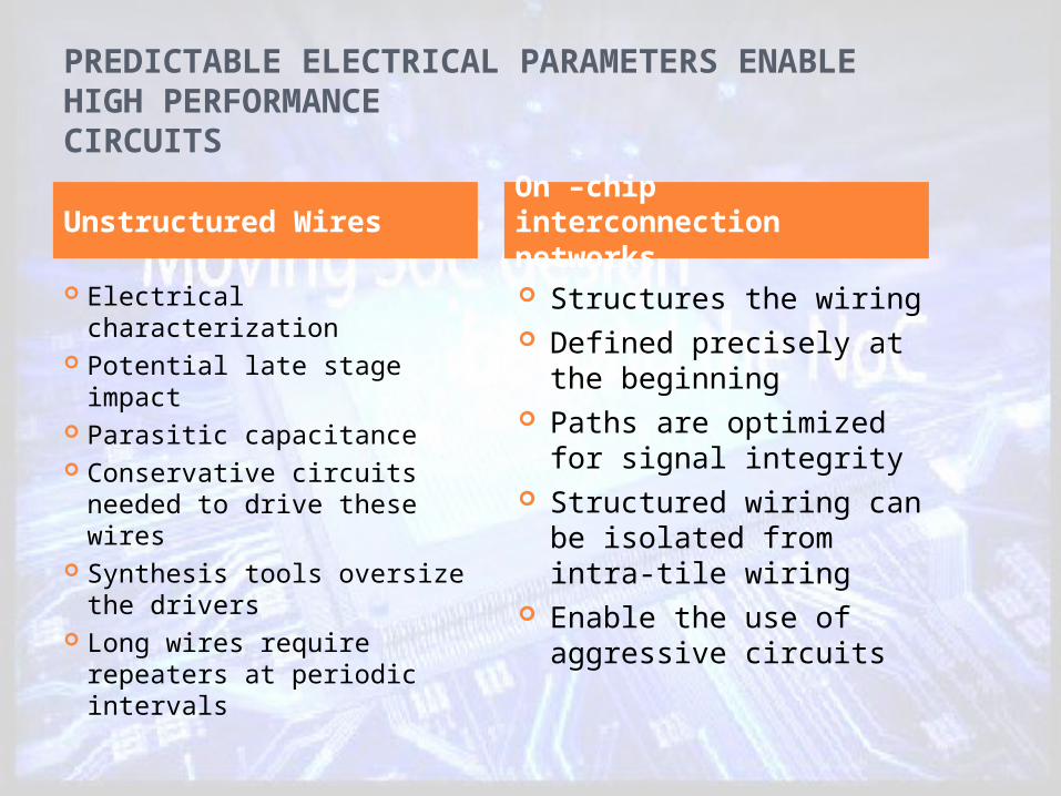
PREDICTABLE ELECTRICAL PARAMETERS ENABLE HIGH PERFORMANCECIRCUITS
Electrical characterization Potential late stage impact Parasitic capacitance Conservative circuits
needed to drive these wires
Synthesis tools oversize the drivers
Long wires require repeaters at periodic intervals
Structures the wiring Defined precisely at the
beginning Paths are optimized for
signal integrity Structured wiring can be
isolated from intra-tile wiring
Enable the use of aggressive circuits
Unstructured WiresOn –chip interconnection networks

FACILITATING REUSE WITH A UNIVERSAL INTERFACE Compatibility and inter-opearbility Extending reuse to network components
On-chip network is reusable Can dedicate more resources to design, validate
and tune the network Flip side- fixing the die size will lead to wastage
of on-chip area On-chip networks improve the duty factor of
wires Shares the wires across many signals

CONCLUSION Advantages of structure, performance and
modularity Well controlled electrical parameters in turn
enable the use of high-performance circuits Enhances modularity by providing standard
interfaceCHALLENGES Topologies must balance power efficiency with
wire utilization New flow control methods are required Network interface support a wide variety of
protocols and data widths

QUESTIONS?


