6
Router and monitoring in production applications By Louis Caron, Sr., Product Manager, Grass Valley, a Belden Brand
| Date post: | 21-Apr-2018 |
| Category: |
Documents |
| Upload: | hoangkhanh |
| View: | 222 times |
| Download: | 3 times |

Router and monitoring in production applicationsBy Louis Caron, Sr., Product Manager, Grass Valley, a Belden Brand
20:07:12
05
10
15
20
2530
35
40
45
50
55

2www.grassvalley.com
APPLICATION NOTE ROUTER AND MONITORING IN PRODUCTION APPLICATIONS
In the last decade a great many changes have positively affected production studio operations, including signifi-cant advances in signal routing and monitoring, which are the focus of this paper.
Until fairly recently, it could be confidently stated that pro-duction studios were, for the most part, relatively static and unchanging when compared to other facilities. Pro-
duction studios were typically “hard wired” to an extent that any changes often required months, even years, of technical plan-ning and preparation before any significant physical modifica-tion could take place. In the case of routing, hard patches could provide some routing flexibility, and a patch was usually enough when a 32x32 router was considered “large.”
It was also true that monitor walls were often static with place-ment being determined, and frequently restricted, more by initial construction plans than operational practicality. Valuable space was often wasted to incorporate monitor bezels and associated UMDs. And because color accuracy was often questionable, some installations preferred to use black and white monitors, which were installed in a way that made them difficult and costly to replace.
However, most contemporary production studios are designed to accommodate complex live productions and, as part of that modernization, are now able to take advantage of flexible, cost-effective routers and virtual multiviewers without exceeding their CAPEX budgets. Monitor walls can now display multiple, high-quality images with accurate color, including remote feeds, rich graphics and additional camera points of view.
However, even though hardware costs are now well within the reach of most modern production facilities, the complexities of signal management — particularly with the onset of multiple HD and 5.1 audio signals — have taken over as a capital-burning concern.
It is therefore vital to develop and deliver technologies and operational pro-cesses that can economically and efficiently address signal management complexities to, ultimately, automate and streamline a production studio’s workflow as much as possible.
Multiviewer Modeled as a Router
Although production studios are far more flexible these days, it also means their signal management configurations are in almost constant flux. Work-flow is managed by constantly re-assigning and re-configuring sources that appear in individual windows on the monitor wall. Although each multi-viewer usually includes individual configuration tools, in most cases, source assignments still have to be modified by operators right before air, some-times even during a show.
To simplify that operation, Grass Valley multiviewers provide a very simple user interface (see Fig. 1) with processors that can instantly assign any source to any window on a monitor wall. Of course, the best method for assigning a source to a monitor is to use the same method used by the routers. Grass Valley’s Kaleido multiviewers see each physical input as a router source and video windows within each display are seen as router destinations. In configurations where a router is partially feeding the multi-viewer with tie lines, these sources, and all sources of the router, automat-ically populate Kaleido’s source list. This means that at any given time the operator can select a destination on the monitor wall and assign a source, irrespective of its origination. For direct sources, Kaleido simply creates a direct port-to-video window assignment. For router sources, Kaleido finds an available path between the router and multiviewer and assigns a port assignment to the video window. The benefit to the workflow (and the op-erator) is that the process is totally transparent.
KX multiviewer
NVISION router
Direct multiviewer
sources
Router sources
Tie-lines
Kaleido-X router
Multiviewer output
Each video window is identified with a destination ID
Kaleido source
database
1 5
7
9
111615
6
8
10
1217
Figure 1: Kaleido-X modeled as a router
3www.grassvalley.com
APPLICATION NOTE ROUTER AND MONITORING IN PRODUCTION APPLICATIONS
When using a router panel, all that is required to reveal the destination IDs on the monitor wall is to press a specific key, then select the monitor destination at the router control panel and assign a source to that monitor.
This approach also has the merit of providing the ability to define specific information and operating parameters for each source entry in a da-tabase. As such, when a source is called up, it arrives with an individual name, tally information, probing data and relevant metadata. However, managing source names requires a few more management techniques.
Managing Source Names
Routing switchers provide a dynamic means of distributing a multitude of sources to monitoring devices and core equipment. Fed partially, or entirely, by a router, the production switcher is one of those core devices. To trace the available sources in each of the switcher’s input ports, as well as identify each source displayed on the monitor wall, a centralized da-tabase of source names is crucial. This system must be able to tag each source with a primary name as well as additional text information, called an alias, related to each signal (see Fig. 2).
It should then be possible for operators to quickly retrieve and display name and alias information for each source, wherever it is assigned or mixed. However, it’s not quite that simple when multiple vendors, or de-vices with varying protocols, are involved.
Grass Valley’s NV9000 router control system provides a convenient solution to this challenge allowing the router controller to act as the primary point of entry for all source names. The router control panel automatically receives both primary names and aliases from the NV9000 controller, which also automatically provides this same information to production switchers, monitor walls and any other device that requires it.
Some applications require dynamic name changes — especially camera aliases — via remote or clip feeds, but they have to be initiated with software that non-technical operators can confidently use without worrying about making inadvertent changes to other functional configura-tions inside the system.
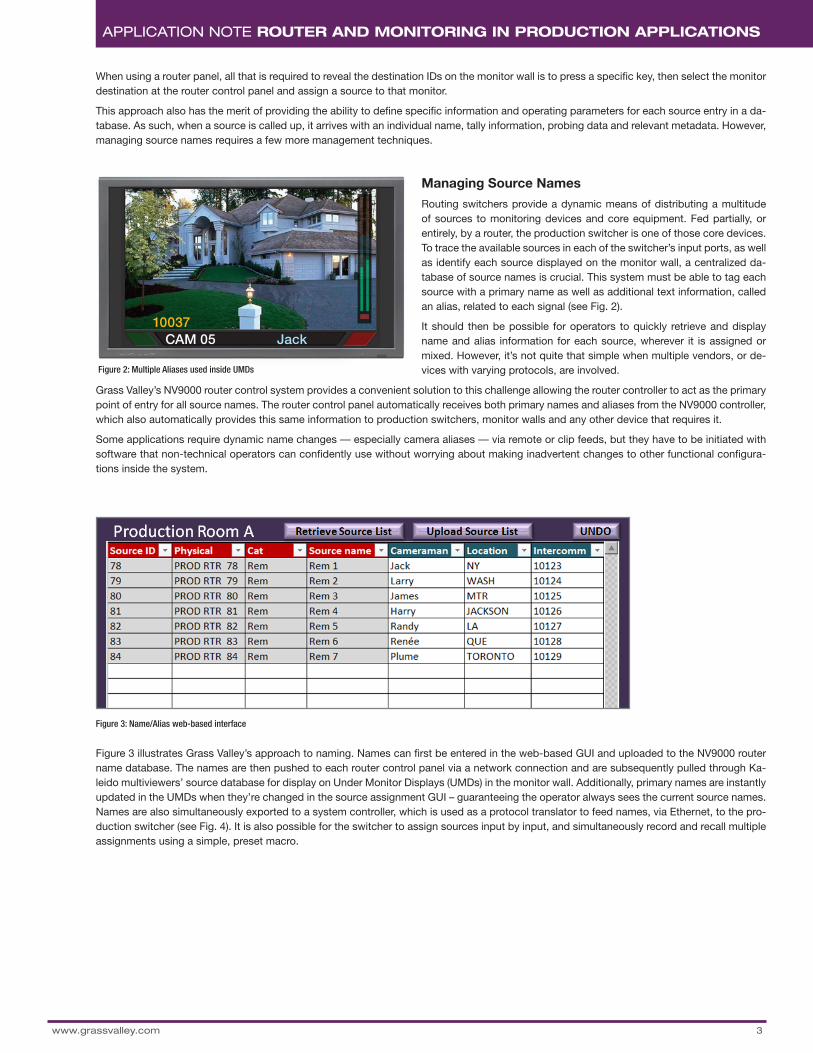
Figure 3 illustrates Grass Valley’s approach to naming. Names can first be entered in the web-based GUI and uploaded to the NV9000 router name database. The names are then pushed to each router control panel via a network connection and are subsequently pulled through Ka-leido multiviewers’ source database for display on Under Monitor Displays (UMDs) in the monitor wall. Additionally, primary names are instantly updated in the UMDs when they’re changed in the source assignment GUI – guaranteeing the operator always sees the current source names. Names are also simultaneously exported to a system controller, which is used as a protocol translator to feed names, via Ethernet, to the pro-duction switcher (see Fig. 4). It is also possible for the switcher to assign sources input by input, and simultaneously record and recall multiple assignments using a simple, preset macro.
10037CAM 05 Jack
Figure 2: Multiple Aliases used inside UMDs
Figure 3: Name/Alias web-based interface
4www.grassvalley.com
APPLICATION NOTE ROUTER AND MONITORING IN PRODUCTION APPLICATIONS
Tally Management System
In terms of tally management, multiple scenarios are possible. When a single switcher is fed by direct sources, simple tally management is all that is necessary. Usually, a single “Program/On Air” tally is sufficient.
However, multiple devices fed by a router make tally management considerably more complex. Additional tally lights are needed to provide preset/preview tally, or additional output tallies that may be essential for the operation. It’s therefore important that tally manage-ment and their associated display systems have enough flexibility to cover any scenario. Below are two examples.
Simple Tally Management
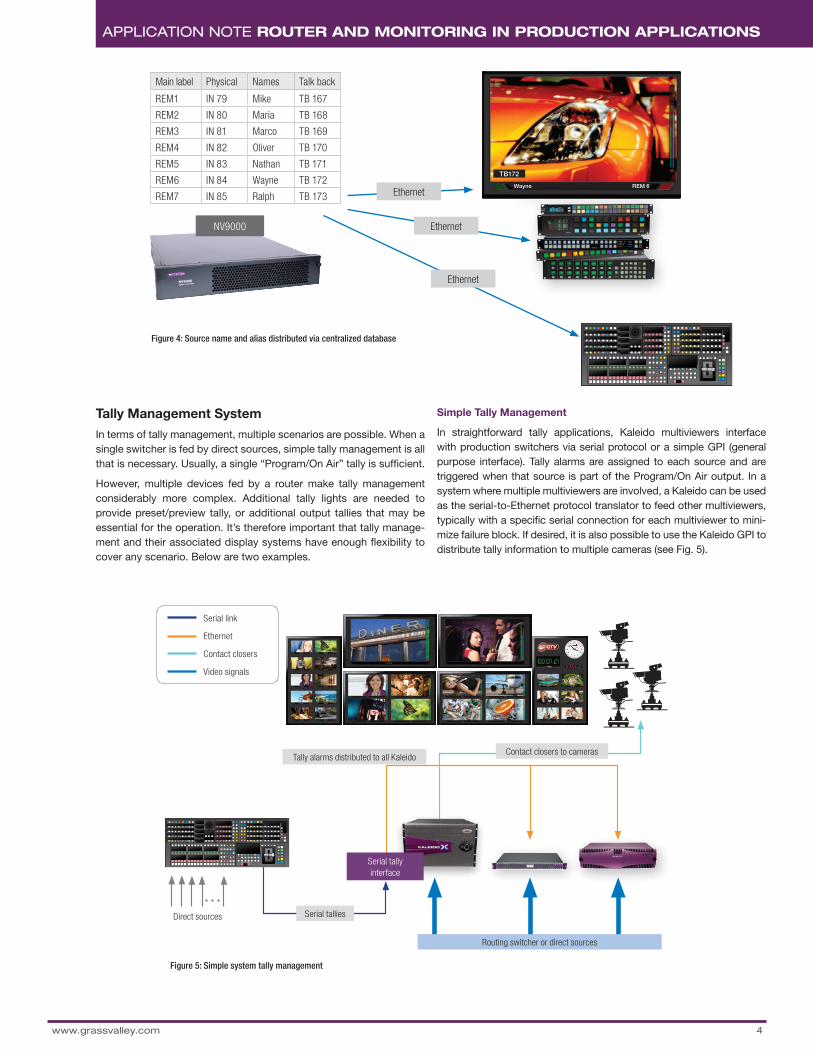
In straightforward tally applications, Kaleido multiviewers interface with production switchers via serial protocol or a simple GPI (general purpose interface). Tally alarms are assigned to each source and are triggered when that source is part of the Program/On Air output. In a system where multiple multiviewers are involved, a Kaleido can be used as the serial-to-Ethernet protocol translator to feed other multiviewers, typically with a specific serial connection for each multiviewer to mini-mize failure block. If desired, it is also possible to use the Kaleido GPI to distribute tally information to multiple cameras (see Fig. 5).
Wayne REM 6
TB172
Main label Physical Names Talk back
REM1 IN 79 Mike TB 167
REM2 IN 80 Maria TB 168
REM3 IN 81 Marco TB 169
REM4 IN 82 Oliver TB 170
REM5 IN 83 Nathan TB 171
REM6 IN 84 Wayne TB 172
REM7 IN 85 Ralph TB 173 Ethernet
Ethernet
Ethernet
NV9000
Figure 4: Source name and alias distributed via centralized database
Serial link
Ethernet
Contact closers
Video signals20:07:12
05
10
15
20
2530
35
40
45
50
55
Tally alarms distributed to all Kaleido
Routing switcher or direct sources
Contact closers to cameras
Serial talliesDirect sources
Serial tally interface
Figure 5: Simple system tally management

5
APPLICATION NOTE ROUTER AND MONITORING IN PRODUCTION APPLICATIONS
Complex Tally Management
Complex tally configurations usually require an external tally man-agement system. The system supplier is responsible for ensuring that tally information can be shared with all devices through appropriate interfaces. Although complex tally requirements are pretty standard these days, most of these systems are complex to program, which can sometimes cause serious trouble for the end-user. For example, modifications of the source mapping may be required after initial com-missioning of the tally controller. Simplification of these tools could make this type of issue less troublesome.
Loading Layouts and Controlling Up/Down Timers
Most production switchers provide defined macro functions that can be recalled via a button on the switcher console. It is then possible, for example, to assign three buttons to start, stop and reset a timer, or to load preset layouts. The ideal implementation of this capability is to create a macro that recalls a dummy router crosspoint. In the case of Kaleido multiviewers, they will monitor the crosspoints and trigger a reaction to their condition.
A Growing Number of Audio Signals to Deal With
As the number of video signals in a facility increases, so does the number of audio signals. Hybrid routers — single-frame routers that can support both video and audio routing, concurrently — are an ideal resource. By having integrated de-embedders and embed-ders, embedded audio that exists in any incoming SDI signal can be de-embedded as it enters the hybrid router. This audio is then sent to a combined video and audio crosspoint array that has access to all of the incoming audio channels. Just like a discrete audio router, the Hybrid audio crosspoint is completely non-blocking and any mono input channel can be routed to any mono output. Additionally, the hybrid router also supports AES and MADI inputs. So, regardless of how the audio enters the router, it all ends up at the same common audio crosspoint and can be routed to any audio output; embedded, discreet or MADI (see Fig. 6). It should be noted that every video and audio path is protected by a redundant crosspoint module. Because there are MADI inputs and outputs, connectivity between the audio production switcher and the router is greatly simplified, a solution that’s ideal in a production environment.
www.grassvalley.com
20:07:12
05
10
15
20
2530
35
40
45
50
55
Audio mixer
Audio Console
Video switcher
MultiviewersHybridvideo
+Audio
routing
Video wirh embedded audio
Video
Video wirh embedded audio
Audio AES and MADI
MADI audio
Enterprise routing
Figure 6: Hybrid routing uses a common audio crosspoint to enable any audio output embedding and re-embedding process, which can cause lip-sync issues

WWW.GRASSVALLEY.COMJoin the Conversation at GrassValleyLive on Facebook, Twitter, YouTube and Grass Valley - A Belden Brand on LinkedIn.
6
Belden, Belden Sending All The Right Signals and the Belden logo are trademarks or registered trademarks of Belden Inc. or its affiliated companies in the United States and other jurisdictions. Grass Valley, Kaleido and NVISION are trademarks or registered trademarks of Grass Valley. Belden Inc., Grass Valley and other parties may also have trademark rights in other terms used herein.
Copyright © 2014 Grass Valley. All rights reserved. Specifications subject to change without notice.
GVB-1-0268A-EN-AN
APPLICATION NOTE ROUTER AND MONITORING IN PRODUCTION APPLICATIONS
To help manage this, Grass Valley has designed ultra-low latency de-embedders and embedders into the Hybrid router. This unique design reduces audio to video delay to just 1-3 video lines. This ap-proach to hybrid routing easily supports many re-entries in the router from the production switcher or other devices.
The largest hybrid router today supports 1024X1024 video signals, and each video stream can support up to 16 mono audio channels. This means the audio crosspoint in the hybrid router must support 16384x16384 signals, and this must be non-blocking. It would be a natural assumption to consider management of this configuration quite complicated. Grass Valley’s NV9000 Router Control System han-dles this complexity for the operator. The operator will use the same processes to control the hybrid router as he would have to control discrete video and audio routers. At the router control panel, the look, feel, configuration and operation remain simple.
Hybrid routers also provide for a simple installation. Traditionally, to have the functionality that a hybrid router offers, external embedders and dis-embedders would be required — consuming valuable space and power, and introducing complexity into the system. A different control surface is also usually required to control the external process-ing, so the operators need more training to manage the system. With a hybrid router all of these metrics are reduced, leading to a lower cost solution that meets the challenge of most production environments.
Conclusion
Production switchers and router control panels are in constant use and the interfaces between them are vital to workflow, so seamless interoperability between multifunction routers and high-end multiview-ers greatly simplify those operations and vastly reduce the margin for error. In short, why make things any more difficult than they have to be?


