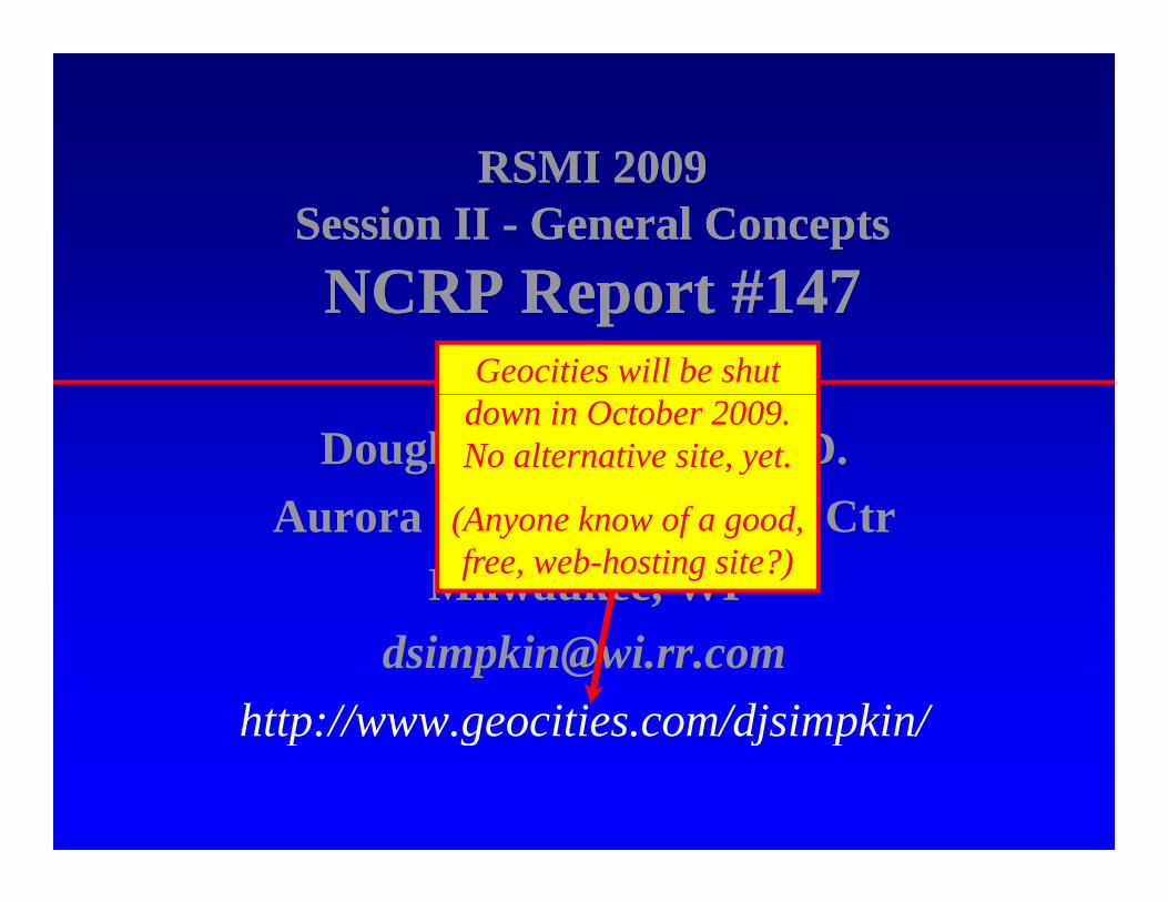
RSMI 2009 RSMI 2009 RSMI 2009 RSMI 2009 Session II Session II - General Concepts General Concepts NCRP R t #147 NCRP R t #147 NCRP Report #147 NCRP Report #147 Douglas J. Simpkin, Ph.D. A St L k ’ M di l Ct Aurora St. Luke’s Medical Ctr Milwaukee, WI [email protected]http://www.geocities.com/djsimpkin/ http://www.geocities.com/djsimpkin/
Transcript
RSMI 2009RSMI 2009RSMI 2009 RSMI 2009 Session II Session II -- General ConceptsGeneral ConceptsNCRP R t #147NCRP R t #147NCRP Report #147NCRP Report #147
Douglas J. Simpkin, Ph.D.A St L k ’ M di l CtAurora St. Luke’s Medical Ctr
RSMI 2009RSMI 2009RSMI 2009 RSMI 2009 Session II Session II -- General ConceptsGeneral ConceptsNCRP R t #147NCRP R t #147NCRP Report #147NCRP Report #147
Geocities will be shut
Douglas J. Simpkin, Ph.D.A St L k ’ M di l Ct
down in October 2009. No alternative site, yet.
(A k f dAurora St. Luke’s Medical CtrMilwaukee, WI
• “Thank You” to Pedro Vas and Bob Dixon for inviting me to this course.g
• My wife and I had hoped to make a holiday of my visit to this beautiful siteof my visit to this beautiful site.
• But our son John & his wife Megan had other plansother plans…
3
Preliminaries
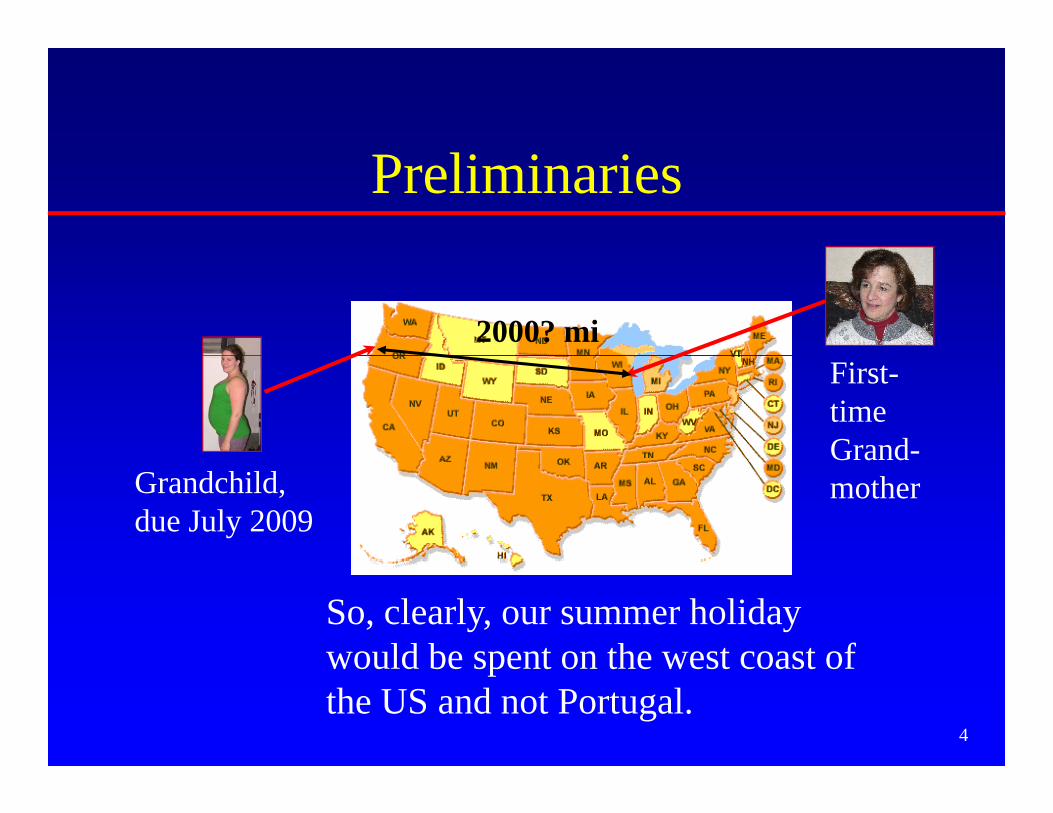
2000? miFirst-time Grand-
Grandchild, due July 2009
Grandmother
So, clearly, our summer holiday would be spent on the west coast of
4
would be spent on the west coast of the US and not Portugal.
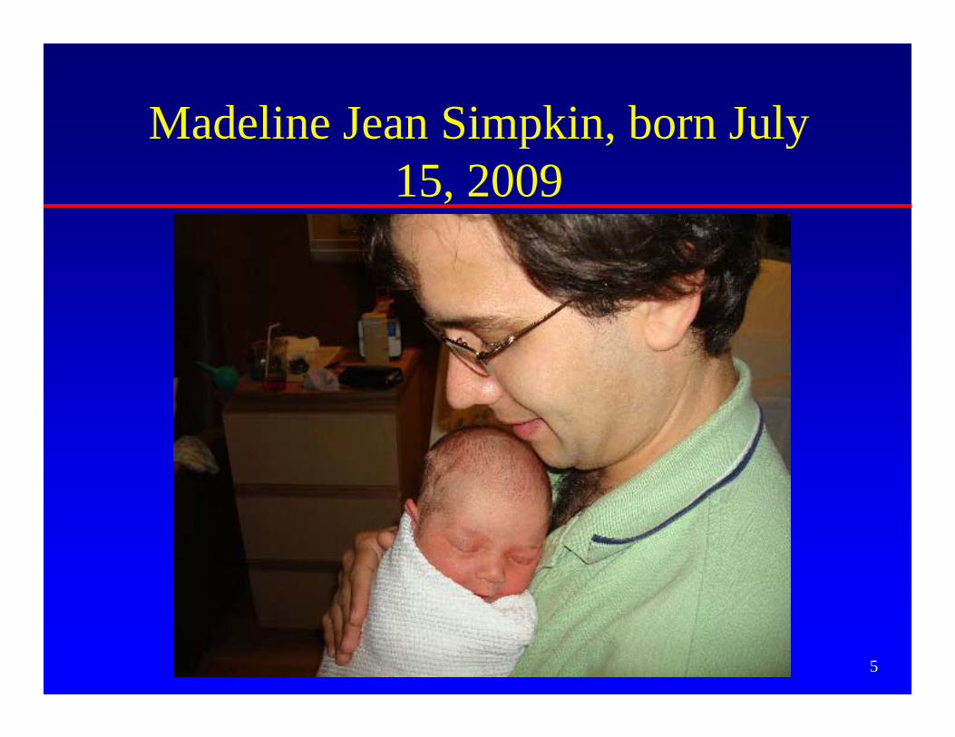
Madeline Jean Simpkin, born JulyMadeline Jean Simpkin, born July 15, 2009
5
AAwww…….
6
I’m No Philosopher• I’m here as a technocrat, an engineer
– Not to argue a dose limit or dose constraint– Rather to solve a problem/ achieve a result
• The method is valid regardless of country of g yorigin or units of measure
7
BackgroundBackgroundBackgroundBackground• The purpose of radiation shielding is to protect
b f th l bli d k f thmembers of the general public and workers from the harmful effects of ionizing radiation and the institution from the harmful effects of an upset s u o o e u e ec s o upseregulator
• Regulatory dose limits define permissible levels• In the USA, regulations come from
– National government for nuclear materialsSt t & l l t f– State & local government for x-ray uses
• Best practices to achieve these regulatory goals refer to the recommendations of independent scientific
8
to the recommendations of independent scientific bodies
BackgroundBackgroundBackgroundBackground
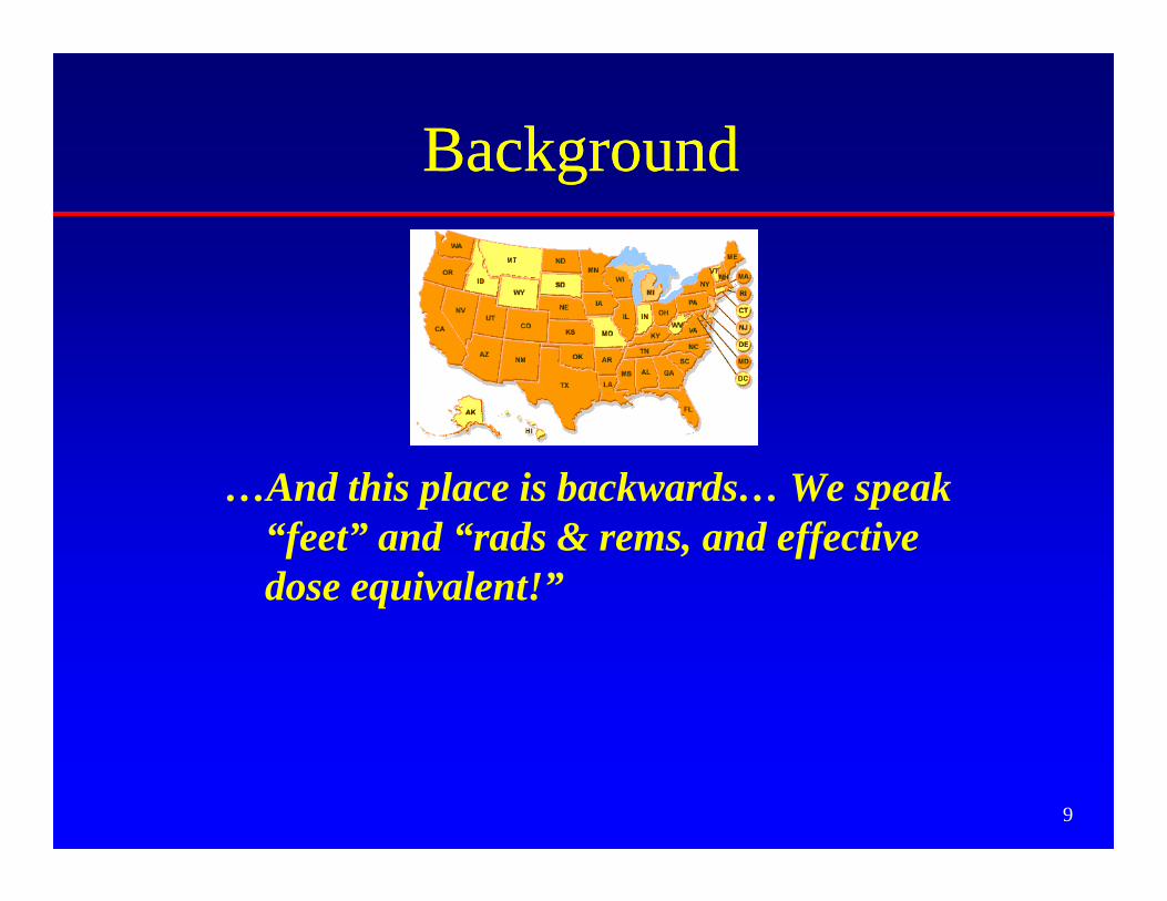
…And this place is backwards… We speak p p“feet” and “rads & rems, and effective dose equivalent!”
9
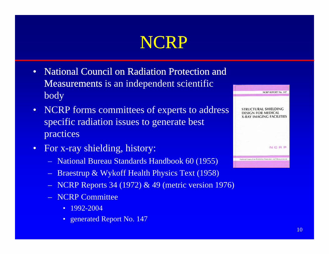
NCRPNCRPNCRPNCRP•• National Council on Radiation Protection and National Council on Radiation Protection and
MeasurementsMeasurements is an independent scientific body
• NCRP forms committees of experts to addressNCRP forms committees of experts to address specific radiation issues to generate best practices
• For x-ray shielding, history:– National Bureau Standards Handbook 60 (1955) – Braestrup & Wykoff Health Physics Text (1958)Braestrup & Wykoff Health Physics Text (1958)– NCRP Reports 34 (1972) & 49 (metric version 1976)– NCRP Committee
• 1992 2004
10
• 1992-2004 • generated Report No. 147
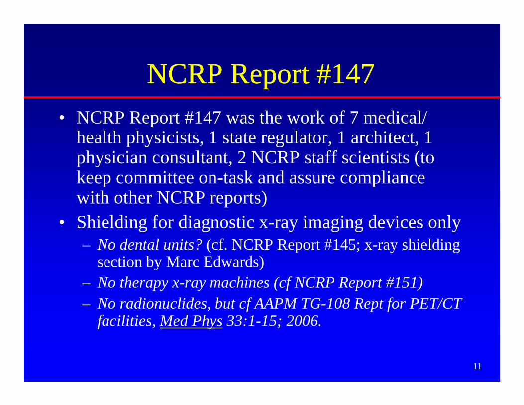
NCRP Report #147NCRP Report #147NCRP Report #147NCRP Report #147• NCRP Report #147 was the work of 7 medical/ p
health physicists, 1 state regulator, 1 architect, 1 physician consultant, 2 NCRP staff scientists (to keep committee on task and assure compliancekeep committee on-task and assure compliance with other NCRP reports)
• Shielding for diagnostic x-ray imaging devices only S e d g o d g os c y g g dev ces o y– No dental units? (cf. NCRP Report #145; x-ray shielding
section by Marc Edwards)N th hi ( f NCRP R t #151)– No therapy x-ray machines (cf NCRP Report #151)
– No radionuclides, but cf AAPM TG-108 Rept for PET/CT facilities, Med Phys 33:1-15; 2006.
11
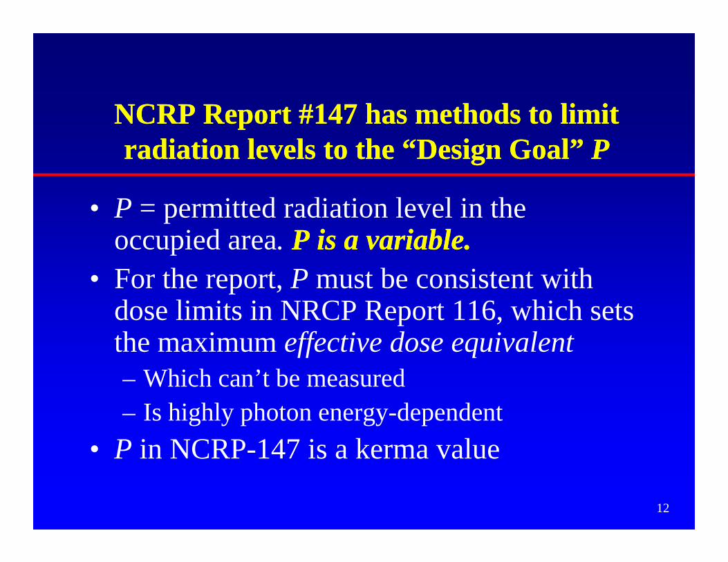
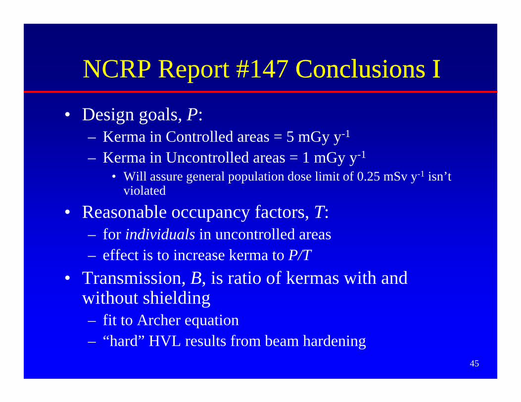
C #14 i iC #14 i iNCRP Report #147 has methods to limit NCRP Report #147 has methods to limit radiation levels to the “Design Goal” radiation levels to the “Design Goal” PP
• P = permitted radiation level in the occupied area P is a variable.P is a variable.occupied area. P is a variable.P is a variable.
• For the report, P must be consistent with dose limits in NRCP Report 116 which setsdose limits in NRCP Report 116, which sets the maximum effective dose equivalent– Which can’t be measured– Is highly photon energy-dependent
• P in NCRP-147 is a kerma value
12
P in NCRP 147 is a kerma value
Design Goal, Design Goal, PPg ,g ,Controlled Area Uncontrolled Area
50 MGY/Y 5 MGY/Y NCRP-491976
50 MGY/Y
= 1 MGY/WK
5 MGY/Y
= 0.1 MGY/WKF ti ( ½) f
NCRP-147
Fraction ( =½) of NCRP-116’s 10 mGy/y limit for new operations 1 mGy/y NCRP 147
2004 = 5 mGy/y (~matches fetal dose limit)
0 1 G / k
y y= 0.02 mGy/wk
= 0.1 mGy/wk
Effect Factor of 10 d
Factor of 5 d
13
ff decrease decrease
General Population Dose Limit:General Population Dose Limit:General Population Dose Limit: General Population Dose Limit: NCRP Rept #147 vs NCRP Rept #116NCRP Rept #147 vs NCRP Rept #116
• NCRP-147 in uncontrolled areas– P = 1 mGy/y,
Whil NCRP 116• While NCRP-116:– “...whenever the potential exists for exposure of an individual
member of the public to exceed 25 % of the annual effective dose limit as a result of irradiation attributable to a single site, the site operator should ensure that the annual exposure of the maximally exposed individual, from all man-made exposures… does not
d 1 S Alt ti l if h t i texceed 1 mSv. Alternatively, if such an assessment is not conducted, no single source or set of sources under one control should result in an individual being exposed to more than 0.25 mSv annually ”
14
mSv annually.
PP=0 1 mGy/y for Uncontrolled areas=0 1 mGy/y for Uncontrolled areasPP=0.1 mGy/y for Uncontrolled areas =0.1 mGy/y for Uncontrolled areas satisfies 0.25 mSv/y Public Dose Limitsatisfies 0.25 mSv/y Public Dose Limit
• Because of the conservative assumptions and methods in NCRP Rept 147:p– Ignoring patient attenuation– Assuming perpendicular beam incidence– Ignoring attenuating items in room (e.g. Pb aprons
on workers, fluoro drapes, etc.)A i l k l l– Assuming worst-case leakage levels
– Assuming conservatively large beam areas for worst case scatter calculations
15
worst-case scatter calculations
PP=0.1 mGy/y for Uncontrolled areas satisfies=0.1 mGy/y for Uncontrolled areas satisfiesPP 0.1 mGy/y for Uncontrolled areas satisfies 0.1 mGy/y for Uncontrolled areas satisfies 0.25 mSv/y Public Dose Limit 0.25 mSv/y Public Dose Limit –– cont.cont.– Assuming conservatively high occupancy factors – In the USA, Pb sheets come in quantized
thicknesses (e.g. 1/32 inch, 1/16 inch, etc). Using the next greater thickness will shield to much lower levels than Plower levels than P
– Assuming minimum distances from source to personnel in occupied areaspersonnel in occupied areas
– At <50 keV, the Effective Dose Equivalent is a small fraction of the kerma (due to shielding of
16
small fraction of the kerma (due to shielding of deep organs by overlying tissues)
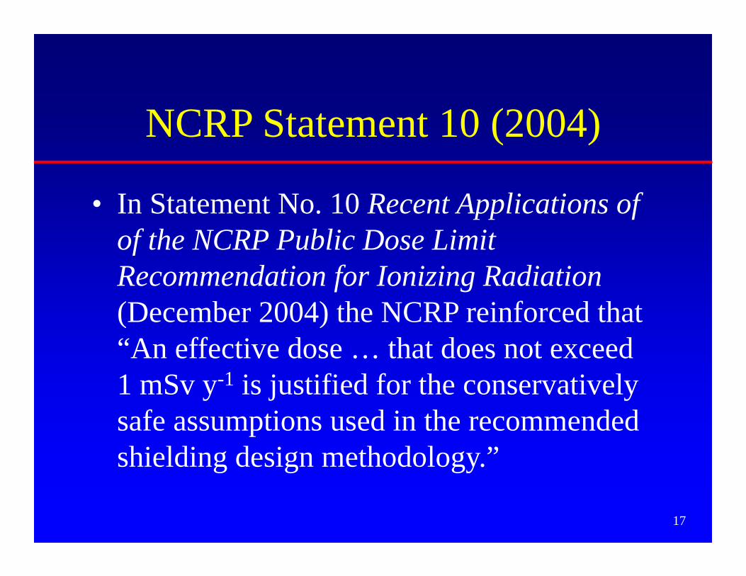
NCRP Statement 10 (2004)
• In Statement No. 10 Recent Applications of of the NCRP Public Dose Limit fRecommendation for Ionizing Radiation (December 2004) the NCRP reinforced that ( )“An effective dose … that does not exceed 1 mSv y-1 is justified for the conservatively y j ysafe assumptions used in the recommended shielding design methodology.”
17
g g gy
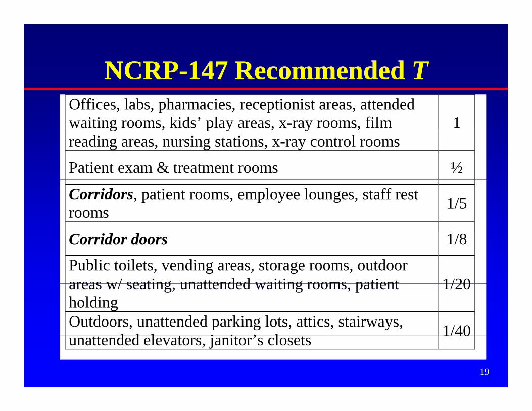
Occupancy FactorOccupancy Factor TTOccupancy Factor, Occupancy Factor, TT• Shield designers allow for partial occupancy g p p y
in shielded areas, with T the “occupancy” factor
• T is the fraction of the beam-on time a shielded area is occupied by an individual
• A barrier is acceptable if it decreases the kerma behind the barrier to P/T
• Note: If T<1, the “full-time kerma” will be P/T
18
NCRPNCRP--147 Recommended147 Recommended TTNCRPNCRP 147 Recommended 147 Recommended TTOffices, labs, pharmacies, receptionist areas, attendedwaiting rooms, kids’ play areas, x-ray rooms, film 1waiting rooms, kids play areas, x ray rooms, filmreading areas, nursing stations, x-ray control rooms
Outdoors, unattended parking lots, attics, stairways,d d l j i ’ l 1/40
19
unattended elevators, janitor’s closets 1/40
Radiation X-Ray Clinic X R Cli i W iti ARadiation Worker
P = 5 mGy y -1 T = 1
VisitorP = 1 mGy y -1
T = 1/20
ReceptionistP = 1 mGy y -1
T = 1
X Ray Clinic X-Ray Clinic Waiting Area
T = 1/20T 1
Lawyer’s Office (not associated with X-Ray Clinic)Members of the PublicP = 1 mGy y -1y yT = 1
206
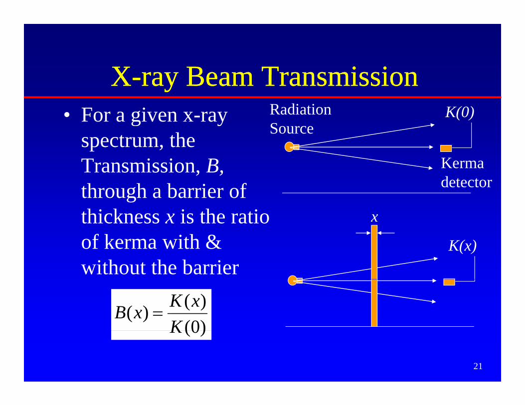
XX ray Beam Transmissionray Beam TransmissionXX--ray Beam Transmissionray Beam Transmission• For a given x-ray K(0)Radiation
Sg y
spectrum, the Transmission, B,
Source
Kerma dthrough a barrier of
thickness x is the ratio x
detector
of kerma with & without the barrier
K(x)
)0()()(
KxKxB =
21
)0(K
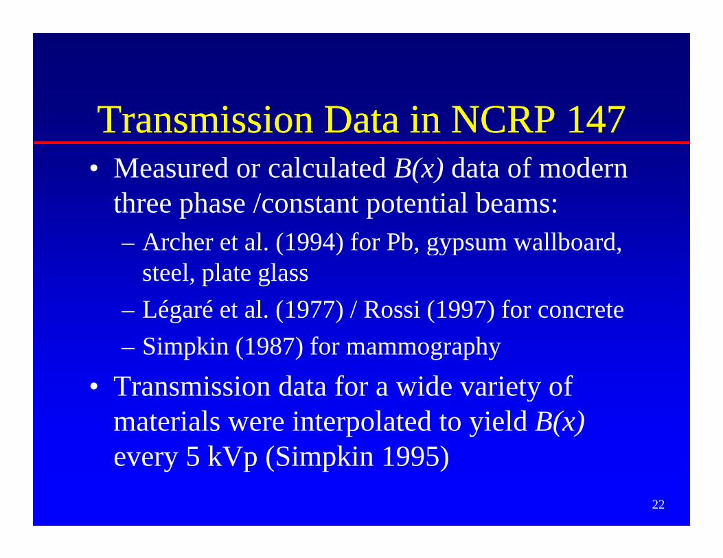
Transmission Data in NCRP 147Transmission Data in NCRP 147• Measured or calculated B(x) data of modernMeasured or calculated B(x) data of modern
three phase /constant potential beams:– Archer et al (1994) for Pb gypsum wallboard– Archer et al. (1994) for Pb, gypsum wallboard,
steel, plate glass– Légaré et al (1977) / Rossi (1997) for concreteLégaré et al. (1977) / Rossi (1997) for concrete – Simpkin (1987) for mammography
• Transmission data for a wide variety of• Transmission data for a wide variety of materials were interpolated to yield B(x)every 5 kVp (Simpkin 1995)
22
every 5 kVp (Simpkin 1995)
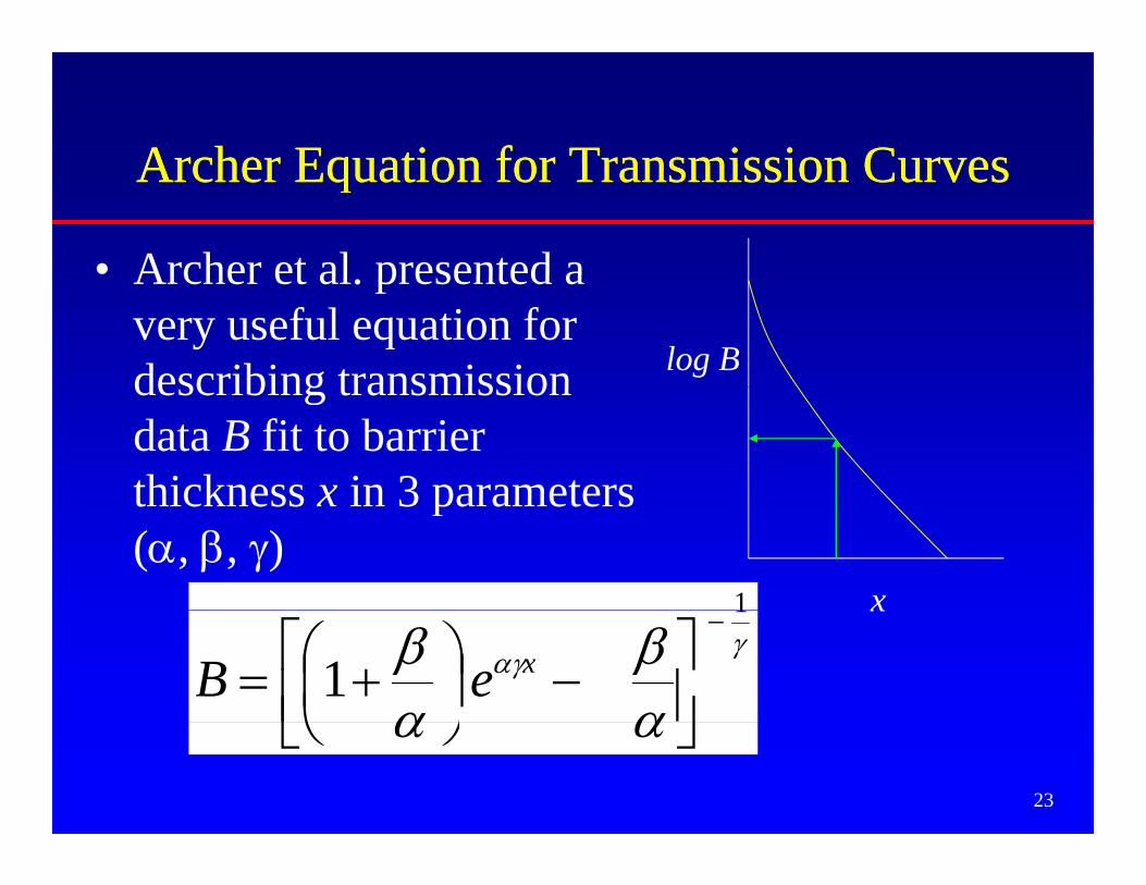
Archer Equation for Transmission CurvesArcher Equation for Transmission CurvesArcher Equation for Transmission CurvesArcher Equation for Transmission Curves
• Archer et al presented aArcher et al. presented a very useful equation for describing transmission log Bdescribing transmission data B fit to barrier thickness x in 3 parametersthickness x in 3 parameters (α, β, γ)
1 xγ
αγ
αβ
αβ
1
1−
⎥⎦⎤
⎢⎣⎡ −⎟
⎠⎞
⎜⎝⎛ += xeB
x
23
αα ⎦⎣ ⎠⎝
Archer Equation for Transmission CurvesArcher Equation for Transmission CurvesArcher Equation for Transmission CurvesArcher Equation for Transmission Curves
• Note: α is the slope of the transmission curve at large x. Therefore, α = (ln 2) / “Hard HVL”
log BFind HVL of curve here (once beam hardening has “straightened curve”)
24
x
Archer Equation for Transmission CurvesArcher Equation for Transmission CurvesArcher Equation for Transmission CurvesArcher Equation for Transmission Curves
• This can be inverted to solve for xThis can be inverted to solve for x
log B
25
x
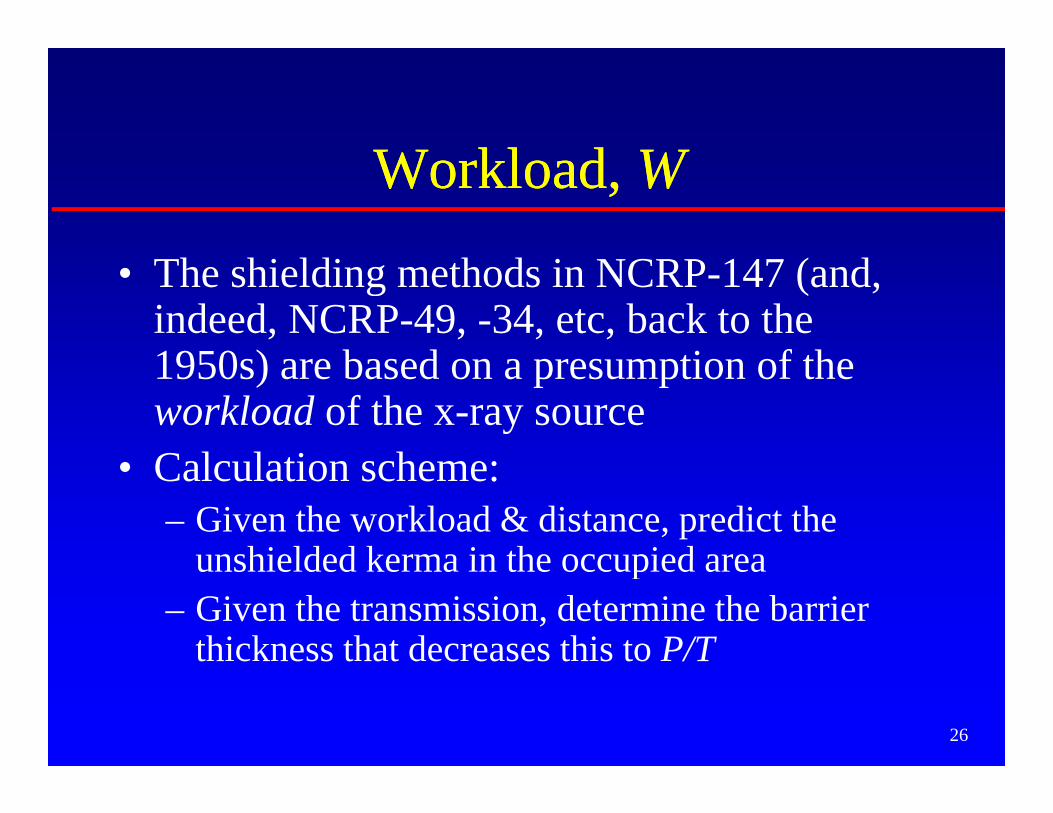
W kl dW kl d WWWorkload, Workload, WW
• The shielding methods in NCRP-147 (and, indeed, NCRP-49, -34, etc, back to the 1950 ) b d ti f th1950s) are based on a presumption of the workload of the x-ray sourceC l l ti h• Calculation scheme:– Given the workload & distance, predict the
unshielded kerma in the occupied areaunshielded kerma in the occupied area– Given the transmission, determine the barrier
thickness that decreases this to P/T
26
W kl dW kl d WWWorkload, Workload, WW
• W is a measure of the x-ray tube’s use• W = the time integral of the tube currentg• Units: mA·min per week (= mAs/60)• W ∝ # electrons hitting x ray tube anode• W ∝ # electrons hitting x-ray tube anode• To be useful, must know or assume the
i i l (kV ) hi h hoperating potential (kVp) at which the workload occurs
27
WorkloadWorkload WWWorkload, Workload, WW• At a given x-ray tube accelerating potential,
h i d f W d i h kthe magnitude of W determines the kerma generated by the tubeTh kV di ib i f W d i b h• The kVp distribution of W determines both the kerma and the transmission of the beam through the barrierthrough the barrier.– Primary beam kerma ∝ kVp2
kerma transmitted through typical shielding– kerma transmitted through typical shielding barriers increases by factors of hundreds going from 60 kVp to 120 kVp
28
WorkloadWorkload WWWorkload, Workload, WW• To determine W used clinically, a survey of
modern medical facilities was undertaken by AAPM TG 9 in the early 1990s and published in 1996 (Simpkin).
• Objectives of survey:j y– W per patient in various types of diagnostic settings
(general radiography, cath lab, etc.)(g g p y )– the weekly average number of patients, N– the kVp distribution of W
29
p– use factors in radiographic rooms
WorkloadWorkload WWWorkload, Workload, WW• Types of Rooms in 1996 Workload Survey:
C di A i h R– Cardiac Angiography Room– Peripheral Angiography Room
(B hi i d h C fil d hi h h l di• (But this missed the Cu-filtered high-heat loading units seen today in Interventional Labs and some fluoroscopic units)
30
fluoroscopic units)
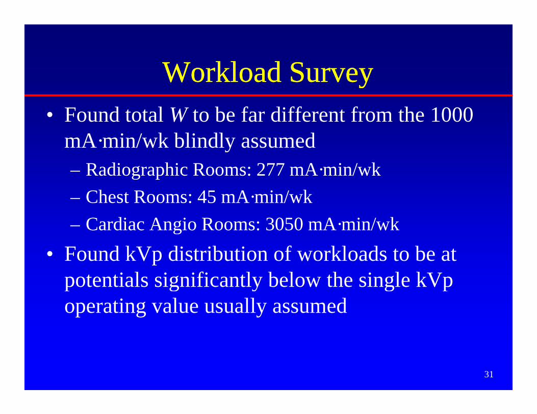
Workload SurveyWorkload SurveyWorkload SurveyWorkload Survey• Found total W to be far different from the 1000
• Found kVp distribution of workloads to be at potentials significantly below the single kVppotentials significantly below the single kVp operating value usually assumed
31
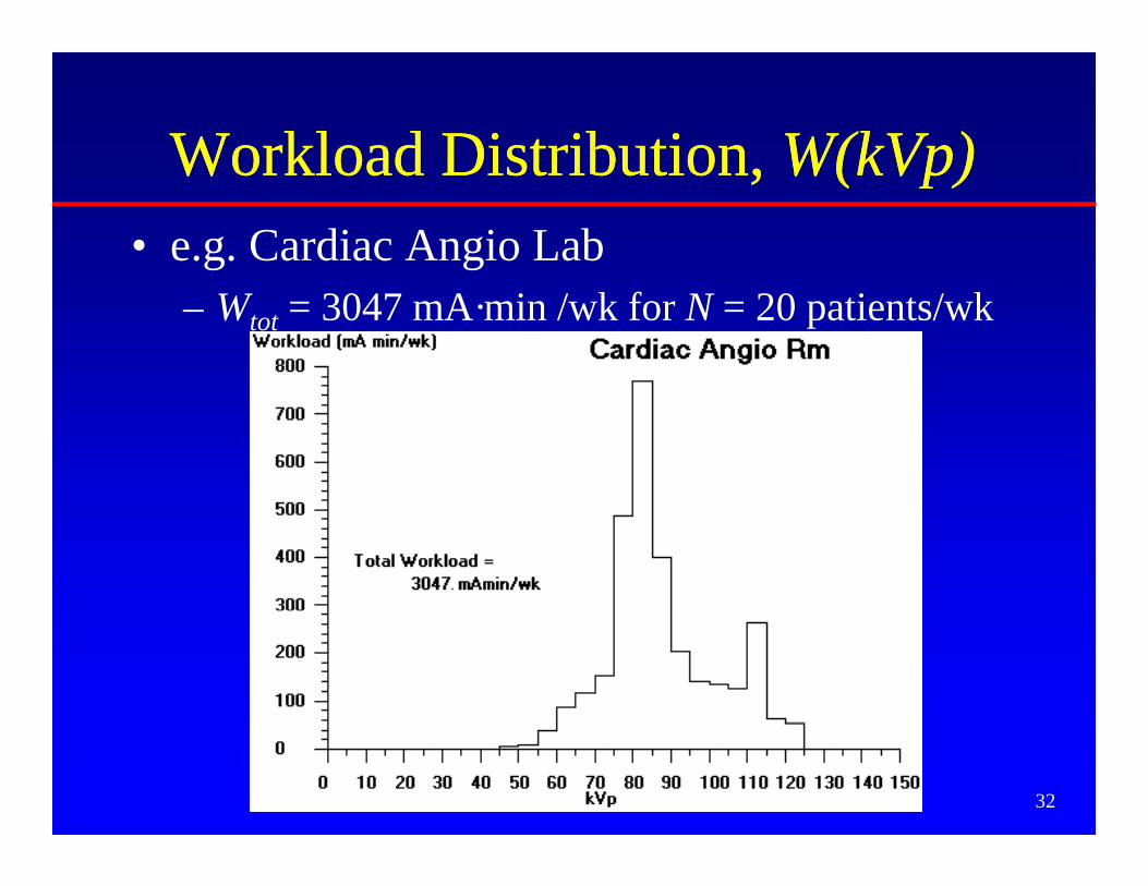
Workload DistributionWorkload Distribution W(kVp)W(kVp)Workload Distribution, Workload Distribution, W(kVp)W(kVp)• e.g. Cardiac Angio Lab
– Wtot = 3047 mA·min /wk for N = 20 patients/wk
32
Workload DistributionWorkload Distribution W(kVp)W(kVp)Workload Distribution, Workload Distribution, W(kVp)W(kVp)• General Radiographic Room; all barriers in room
– Wtot = 277 mA·min /patient for N = 112 patients/wk
33
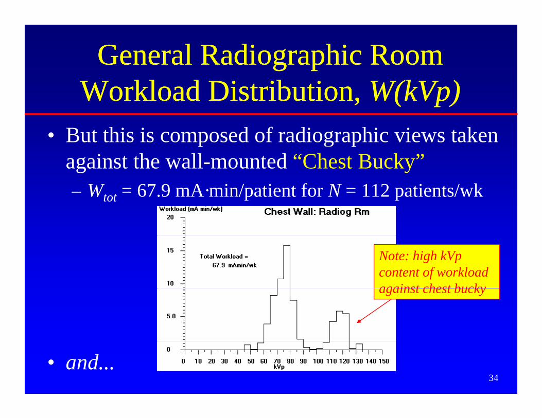
General Radiographic Room General Radiographic Room Workload Distribution, Workload Distribution, W(kVp)W(kVp)
B t thi i d f di hi i t k• But this is composed of radiographic views taken against the wall-mounted “Chest Bucky”– Wtot = 67.9 mA·min/patient for N = 112 patients/wk
Note: high kVp content of workload against chest buckyagainst chest bucky
34• and...
General Radiographic Room General Radiographic Room Workload Distribution, Workload Distribution, W(kVp)W(kVp)
A d di hi i t k i t ll th• And radiographic views taken against all other barriers (floor, other walls, etc)– Wtot = 209 mA·min/patient for N = 112 patients/wk
Note: very little high kVp content of workload againstworkload against anything but chest bucky
35
Where in the occupied area do Where in the occupied area do ppyou calculate the kerma?you calculate the kerma?
0.5 m
0.3 m = 1 ftTo the closest i i !sensitive organ!
1.7 m = 5.5 ft
36
NCRPNCRP--147 Models for Diagnostic147 Models for DiagnosticNCRPNCRP 147 Models for Diagnostic 147 Models for Diagnostic XX--Ray Shielding CalculationsRay Shielding Calculations
Yes No
37
Yes
The Three Models for DiagnosticThe Three Models for DiagnosticThe Three Models for Diagnostic The Three Models for Diagnostic XX--ray Shielding In NCRP 147ray Shielding In NCRP 147
1. First-principle extensions to NCRP 492. Presuming workload distribution, NCRP-147
gives kerma per patient at 1 m for various types f Th l b # ti t dof x-ray room use. Then scale by # patients and
inverse-squared distance, and use transmission curves designed for particular room typescurves designed for particular room types.
3. For complicated source geometries, useNT/(Pd2) formalism.
38
NT/(Pd ) formalism.
The Three Models In NCRP 147The Three Models In NCRP 147• cf Table 5.1 for a “road map” on how to use
the data in NCRP 147 to solve shielding problems of the various room types
• Chapter 5 gives examples using these shielding models Much more tomorrow
39
shielding models…. Much more tomorrow.
CT Scanner Shielding: OverviewCT Scanner Shielding: OverviewCT Scanner Shielding: OverviewCT Scanner Shielding: Overview• Estimate unshielded weekly kerma in occupied y p
area near scanner, Kun– Use DLP and # patients to state workload
• Know P/T• Barrier requires transmission TPB /
=q• Get barrier thickness
– Simpkin Health Phys 58, 363-7: 1990 (refit in
unK
p y , (NCRP-147)
• More from Bob Dixon tomorrow
40
f
Result: CT Scanner in a Shielding CaveResult: CT Scanner in a Shielding Cave
ADD Pb to ceilingADD Pb to ceiling
Light-weight concrete floors/ ceilings are often
CT
ADD Pb to ceiling ADD Pb to ceiling (~1 mm)(~1 mm)
ADD Pb to ADD Pb to wall above wall above 2.1 m (~1 2.1 m (~1
g ftoo thin!
“Normal” wall shielding to 2.1 m
CT Scanner
((mm)mm)
ADD Pb to floorADD Pb to floortyp 3 m
ADD Pb to floor ADD Pb to floor (~1 mm)(~1 mm)
41
Surveys of X-ray ShieldingSurveys of X ray Shielding• After installation of shielding, should inspect for
voids in the shieldingvoids in the shielding– Lead-lined dry wall installed upside down= big gap in
the shielding near the floor– Lead in walls not lapped into door/window frames– Gaps between lead sheets
H l ( l t i l tl t j ti b l bi– Holes (e.g. electrical outlets, junction boxes, plumbing, air conditioning ducts) put into installed shielding. Such voids must be backed with shielding materials.
• Do inspection by– Visually
By transmission survey with nuclear source & sensitive
42
– By transmission survey with nuclear source & sensitive survey meter (GM or NaI)
Surveys of X-ray Shielding• After installation of shielding, should assureAfter installation of shielding, should assure
adequacy of installed barriers. (That is, “Are they thick enough?”)
i l i i b f ll l d– Visual inspection before walls are closed up.– Transmission measurements through barriers
• Generally point measurements that may not be typical of whole y p y ypbarrier.
• Sources:– Gamma ray source (but don’t violate any licensing issues!)– X-ray source (but don’t burn up the x-ray tube)
– Difficulties may arise if evaluator uses different assumptions from designer.
43
p g
Surveys of X-ray ShieldingC t h t i i t• Can turn such transmission measurements around and redo the shielding calculation to
di t th i b f ti tpredict the maximum number of patients that can be imaged in the room without