344
RTD LIGHT RAIL DESIGN CRITERIA Regional Transportation District Issued September 2014 Correction 1 Issued December 2014

RTD
LIGHT RAIL
DESIGN CRITERIA
Regional Transportation District
Issued September 2014
Correction 1 Issued December 2014

Regional Transportation District Table of Contents
Light Rail Design Criteria September 2014
Page 1 of 1
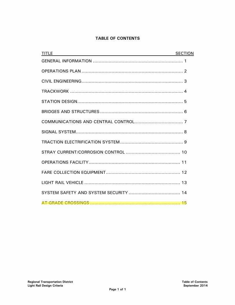
TABLE OF CONTENTS
TITLE SECTION
GENERAL INFORMATION ............................................................... 1
OPERATIONS PLAN ....................................................................... 2
CIVIL ENGINEERING ....................................................................... 3
TRACKWORK ............................................................................... 4
STATION DESIGN .......................................................................... 5
BRIDGES AND STRUCTURES .......................................................... 6
COMMUNICATIONS AND CENTRAL CONTROL.................................. 7
SIGNAL SYSTEM ........................................................................... 8
TRACTION ELECTRIFICATION SYSTEM ............................................ 9
STRAY CURRENT/CORROSION CONTROL ...................................... 10
OPERATIONS FACILITY ................................................................ 11
FARE COLLECTION EQUIPMENT .................................................... 12
LIGHT RAIL VEHICLE ................................................................... 13
SYSTEM SAFETY AND SYSTEM SECURITY .................................... 14
AT-GRADE CROSSINGS ............................................................... 15

Regional Transportation District
Our mission:
To:
To meet our constituents' present and future public transit needs by offering safe. clean. reliable, courteous, accessible and cost-effective service throughout the District.
Richard F. Clarke, Assistant General Manager, Capital Programs
Memorandum
David Genova, Assistant General Manager, Safety, Security and Facilities Austin Jenkins, Assistant General Manager, Rail Operations
From: John Shonsey, Project Manager Henry Stopplecamp, Sr. Manager, Engineering/Chief Engineer
Date: September 23, 2014
Subject: Light Rail Design Criteria
The Light Rail Design Criteria is being modified in the area of at-grade crossing criteria. These modifications are a revision to the March 2013 Light Rail Design Criteria and will take precedence to the contents contained in the March 2013 version of the manual with this approval. The criteria are established as general criteria to be used in the planning and design process. Deviations may be required from these accepted criteria in specific instances. Any such deviations from these accepted criteria must be approved by RTD's Executive Safety & Security Committee.
Coordination with local agencies and jurisdictions is still required for the determination and approval for fire protection, life safety, and security measures that will be implemented as part of the planning and design of the light rail system. It is not proposed that the existing system or any system that is currently under construction where the crossing treatment complies with the MUTCD and is approved by the PUC be modified to comply with all elements of these modifications to the Light Rail Design Criteria. The existing system may be brought into compliance with these modifications if they are in variance with them as future projects or modifications to the crossings are implemented.
The attached modifications include a new section to the Light Rail Design Criteria entitled AT-GRADE CROSSINGS, and the deletion of Sections 3.4.6 and 14.9 as these sections are now included in Section 15 of the criteria.
This manual will be updated periodically either in part or in whole as deemed appropriate by RTD. Any updates or modifications to the manual will take precedence over previous versions or criteria at the time of approval of the updated material or sections of the manual.
Submitted by :
John Shonsey, P.E. Project Manager
Approved by:
Richard F. Clarke Assistant General Manager
c;:~--~-David Genova Assistant General Manager Safety, Security and Facilities
ins Assistan eneral Manager Rail Operations
Regional Transportation District Table of Contents
Light Rail Design Criteria September 2014
Page 1 of 1
TABLE OF CONTENTS
TITLE SECTION
GENERAL INFORMATION ............................................................... 1
OPERATIONS PLAN ....................................................................... 2
CIVIL ENGINEERING ....................................................................... 3
TRACKWORK ............................................................................... 4
STATION DESIGN .......................................................................... 5
BRIDGES AND STRUCTURES .......................................................... 6
COMMUNICATIONS AND CENTRAL CONTROL.................................. 7
SIGNAL SYSTEM ........................................................................... 8
TRACTION ELECTRIFICATION SYSTEM ............................................ 9
STRAY CURRENT/CORROSION CONTROL ...................................... 10
OPERATIONS FACILITY ................................................................ 11
FARE COLLECTION EQUIPMENT .................................................... 12
LIGHT RAIL VEHICLE ................................................................... 13
SYSTEM SAFETY AND SYSTEM SECURITY .................................... 14
AT-GRADE CROSSINGS ............................................................... 15
Regional Transportation District Section 1 – General Information Light Rail Design Criteria March 2013
Page 1 of 12
SECTION 1 – GENERAL INFORMATION 1.1 PURPOSE .................................................................................................... 2 1.2 SCOPE ........................................................................................................ 2 1.3 PROCEDURES .............................................................................................. 3 1.4 DESIGN CODES AND MANUALS .................................................................... 3 1.5 CLIMATIC CONDITIONS CRITERIA FOR SYSTEMS DESIGN ................................ 4 1.6 ACRONYMS AND ABBREVIATIONS ................................................................ 7 1.7 UNITS OF MEASURE................................................................................... 11
Regional Transportation District Section 1 – General Information Light Rail Design Criteria March 2013
Page 2 of 12
SECTION 1 – GENERAL INFORMATION
1.1 PURPOSE
This manual establishes basic criteria to be used in the design of the Regional Transportation District's (RTD) Light Rail Transit (LRT) system. In addition, drafting standards, directive or sample drawings and management procedures have been prepared to standardize and guide the design activities and the preparation of contract documents. (See separate design criteria for Commuter Rail.)
Design is to be directed toward minimum feasible costs for design, construction, capital facilities and operation; minimum energy consumption and minimum disruption of local businesses and communities. It should be consistent with system reliability, passenger comfort, mode of operation, type of light rail vehicle (LRV) to be used and maintenance. Safety for passengers, workers and the public is of primary importance.
1.2 SCOPE
The Design Criteria will take precedence over all other standards referred to herein except those fixed by legislation.
Specific attention should be given to the Americans with Disabilities Act (ADA), the ADA Accessibility Guidelines for Building and Facilities (ADAAG), the ADA Accessibility Guidelines for Transportation Vehicles and to any succeeding modifications that may be issued. The applicability of those documents is noted in several sections of this manual where it appears to be particularly appropriate. However, the regulations must be adhered to in all areas, whether or not mentioned herein.
The Design Criteria in this manual relates to the following elements of the LRT systems:
• Civil and Structural Engineering
• Track Geometry and Trackwork
• Utilities
• Landscaping
• Stations
• Operations Facility
• Traction Electrification System
• Signal System
• Communications and Central Control
• Stray Current/Corrosion Control
• Fare Collection Equipment
• Light Rail Vehicles
• System Safety and Security
Regional Transportation District Section 1 – General Information Light Rail Design Criteria March 2013
Page 3 of 12
1.3 PROCEDURES
Design Engineers shall prepare drawings and technical specifications for each contract of the project in accordance with their design contract (if applicable) and the following RTD documents:
• Design Criteria Manuals
• CADD Standards
• Contract Requirements
• All other applicable requirements including codes, regulatory standards and environmental impact statements
Deviations may be made within the framework of the Design Criteria to meet the requirements of a particular problem. However, any deviation, discrepancy or unusual solution must be approved by RTD before it can be included in the design. It is the responsibility of the Design Engineer to identify, explain and justify any deviation from the established criteria and to secure the necessary approvals from RTD. Any variation from these Design Criteria must be submitted to and approved by RTD’s Executive Safety and Security Committee.
All proposed deviations to these criteria shall be approved by RTD in writing.
1.4 DESIGN CODES AND MANUALS
In addition to this Design Criteria Manual, the Design Engineer must comply with all other applicable engineering codes and standards, including those of the various Federal, State, and local jurisdictions.
If codes and/or manuals are specified herein for the design of an element of the RTD LRT system, then the most recent edition(s) shall be used. Responsibility for design remains with the Design Engineer in accordance with the terms and conditions of their contract with RTD.
Where design codes conflict with each other, the Design Engineer shall notify RTD in writing and recommend a solution. The Design Engineer shall also investigate those codes and manuals that have precedence.
Specific codes and standards include, but are not limited to, the following:
• Americans with Disabilities Act (ADA)
• Americans with Disabilities Act Accessibility Guidelines for Buildings and Facilities (ADAAG)
• Americans with Disabilities Act Accessibility Guidelines for Transportation Vehicles
• Colorado Department of Transportation (CDOT) - Standard Specifications for Road and Bridge Construction
• CDOT - Standard Plans (M&S Standards)
• CDOT - Highway Design Manual
Regional Transportation District Section 1 – General Information Light Rail Design Criteria March 2013
Page 4 of 12
• CDOT – Drainage Design Manual
• City and County of Denver - Rules for Street Standards
• City and County of Denver - Standard Construction Specifications
• FHWA - Manual on Uniform Traffic Control Devices for Streets and Highways (MUTCD)
• Colorado Public Utilities Commission (PUC)
• RTD - Commuter Rail Design Criteria
• RTD - Design Guidelines and Criteria for Bus Transit Facilities
• RTD - Standard Plans for Bus & Light Rail Transit Facilities
• 2009 International Building Code
• 2009 International Fire Code
• International Energy Conservation Code 2009 (IECC)
• American Association of State Highway and Transportation Officials (AASHTO) - Standard Specifications for Highway Bridges
• AASHTO - Standard Specifications for Structural Supports for Highway Signs, Luminaries, and Traffic Signals
• Transit Cooperative Research Program (TCRP) No. 57 " Track Design Handbook for Light Rail Transit"
• American Railway Engineering and Maintenance Association (AREMA)
• American Institute of Steel Construction (AISC)
• American Welding Society (AWS)
• American Concrete Institute (ACI)
• American Society for the Testing of Materials (ASTM)
• National Bureau of Standards
• National Electric Code (NEC)
• National Electric Safety Code (NESC)
• American National Standards Institute (ANSI)
• National Fire Protection Association (NFPA) including NFPA 130 and 101
• Local jurisdictional codes, requirements and ordinances, as applicable
Individual sections of these criteria may also define additional code requirements.
1.5 CLIMATIC CONDITIONS FOR SYSTEMS DESIGN
The Denver metropolitan area, within which RTD operates, is situated at the foot of the eastern slope of the Rocky Mountains in central Colorado. The area has a semi-arid climate that is somewhat characteristic of the High Plains, but is modified by the Rocky Mountains to the west. Because of this, Denver lies in a belt where there is a fairly rapid change in climate from the foothills to the plains. This change is largely caused by the increase in elevation as you travel west to the foothills. Denver has an elevation of 5,280 feet.
Regional Transportation District Section 1 – General Information Light Rail Design Criteria March 2013
Page 5 of 12
The average annual temperature is about 50°F at this elevation, though this varies a few degrees as elevation changes. The wide average range in daily temperature of 25° to 30°F in the Denver metropolitan area and a wide average range in annual temperature are typical for the High Plains. Variations in temperature are wide from day to day; extremely hot weather in summer and extremely cold weather in the winter normally do not last long and are followed by much more moderate temperatures.
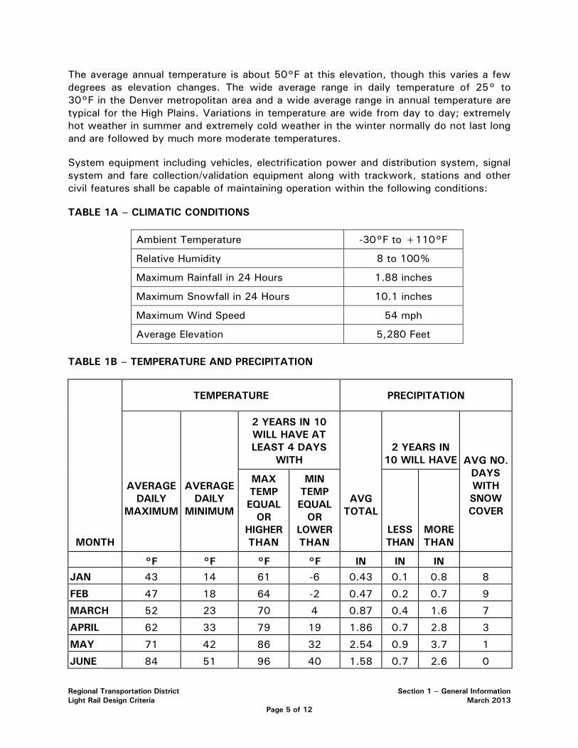
System equipment including vehicles, electrification power and distribution system, signal system and fare collection/validation equipment along with trackwork, stations and other civil features shall be capable of maintaining operation within the following conditions:
TABLE 1A – CLIMATIC CONDITIONS
Ambient Temperature -30°F to +110°F
Relative Humidity 8 to 100%
Maximum Rainfall in 24 Hours 1.88 inches
Maximum Snowfall in 24 Hours 10.1 inches
Maximum Wind Speed 54 mph
Average Elevation 5,280 Feet
TABLE 1B – TEMPERATURE AND PRECIPITATION
TEMPERATURE PRECIPITATION
MONTH
AVERAGE DAILY
MAXIMUM
AVERAGE DAILY
MINIMUM
2 YEARS IN 10 WILL HAVE AT LEAST 4 DAYS
WITH
AVG TOTAL
2 YEARS IN 10 WILL HAVE AVG NO.
DAYS WITH SNOW COVER
MAX TEMP EQUAL
OR HIGHER THAN
MIN TEMP EQUAL
OR LOWER THAN
LESS THAN
MORE THAN
°F °F °F °F IN IN IN JAN 43 14 61 -6 0.43 0.1 0.8 8
FEB 47 18 64 -2 0.47 0.2 0.7 9
MARCH 52 23 70 4 0.87 0.4 1.6 7
APRIL 62 33 79 19 1.86 0.7 2.8 3
MAY 71 42 86 32 2.54 0.9 3.7 1
JUNE 84 51 96 40 1.58 0.7 2.6 0
Regional Transportation District Section 1 – General Information Light Rail Design Criteria March 2013
Page 6 of 12
TEMPERATURE PRECIPITATION
MONTH
AVERAGE DAILY
MAXIMUM
AVERAGE DAILY
MINIMUM
2 YEARS IN 10 WILL HAVE AT LEAST 4 DAYS
WITH
AVG TOTAL
2 YEARS IN 10 WILL HAVE AVG NO.
DAYS WITH SNOW COVER
MAX TEMP EQUAL
OR HIGHER THAN
MIN TEMP EQUAL
OR LOWER THAN
LESS THAN
MORE THAN
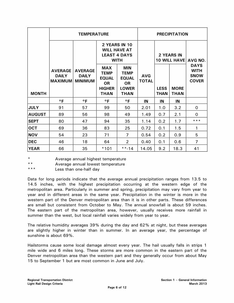
°F °F °F °F IN IN IN JULY 91 57 99 50 2.01 1.0 3.2 0
AUGUST 89 56 98 49 1.49 0.7 2.1 0
SEPT 80 47 94 35 1.14 0.2 1.7 ***
OCT 69 36 83 25 0.72 0.1 1.5 1
NOV 54 23 71 7 0.54 0.2 0.9 5
DEC 46 18 64 2 0.40 0.1 0.6 7
YEAR 66 35 *101 **-14 14.05 9.2 18.3 41
* Average annual highest temperature ** Average annual lowest temperature *** Less than one-half day
Data for long periods indicate that the average annual precipitation ranges from 13.5 to 14.5 inches, with the highest precipitation occurring at the western edge of the metropolitan area. Particularly in summer and spring, precipitation may vary from year to year and in different areas in the same year. Precipitation in the winter is more in the western part of the Denver metropolitan area than it is in other parts. These differences are small but consistent from October to May. The annual snowfall is about 59 inches. The eastern part of the metropolitan area, however, usually receives more rainfall in summer than the west, but local rainfall varies widely from year to year.
The relative humidity averages 39% during the day and 62% at night, but these averages are slightly higher in winter than in summer. In an average year, the percentage of sunshine is about 69%.
Hailstorms cause some local damage almost every year. The hail usually falls in strips 1 mile wide and 6 miles long. These storms are more common in the eastern part of the Denver metropolitan area than the western part and they generally occur from about May 15 to September 1 but are most common in June and July.

Regional Transportation District Section 1 – General Information Light Rail Design Criteria March 2013
Page 7 of 12
Requirements for climatic conditions defined in other sections of these Design Criteria take precedence.
The District is generally located at 40⁰ North Latitude and 105⁰ West Longitude. The Denver area 10-year average insolation (the amount of solar energy per square meter per day) is 4.55 kWh/m2/day.
1.6 ACRONYMS AND ABBREVIATIONS
The following acronyms and abbreviations appear in this document. They are defined as indicated:
AAR Association of American Railroads AASHTO American Association of State Highways and Transportation Officials ABS Automatic Block Signals AC Alternating Current ACI American Concrete Institute ACOE Army Corps of Engineers ADA Americans with Disabilities Act ADAAG Americans with Disabilities Act Accessibility Guidelines for Buildings and
Facilities AFC Automatic Fare Collection AFI Air Filter Institute AFO Audio Frequency Overlay AISC American Institute of Steel Construction AISI American Iron and Steel Institute AMCA Air Moving and Conditioning Association, Inc. ANSI American National Standard Institute APTA American Public Transportation Association AREMA American Railway Engineering and Maintenance Association ARI Air Conditioning and Refrigeration Institute ASA Acoustical Society of America ASCII American Standard Code for Information Interchange ASHRAE American Society of Heating, Refrigeration and Air Conditioning Engineers ASIC Application Specific Integrated Circuit ASME American Society of Mechanical Engineers ASTM American Society for Testing and Materials ATP Automatic Train Protection ATS Automatic Train Stop AWO Maximum empty vehicle operating weight: 97,000 Ib
Regional Transportation District Section 1 – General Information Light Rail Design Criteria March 2013
Page 8 of 12
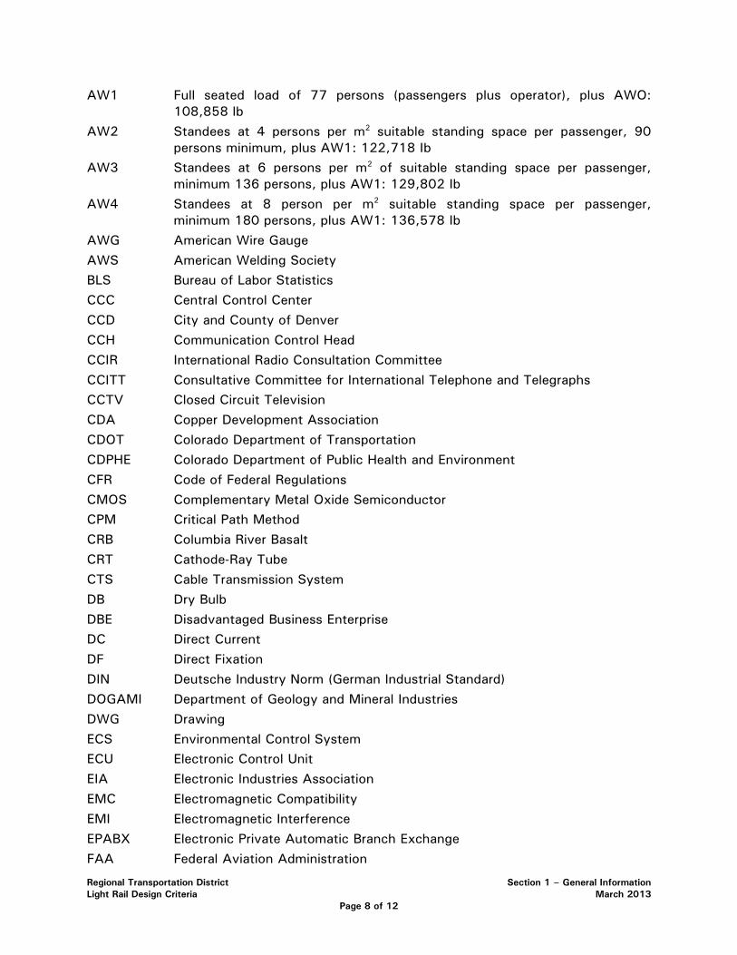
AW1 Full seated load of 77 persons (passengers plus operator), plus AWO: 108,858 lb
AW2 Standees at 4 persons per m2 suitable standing space per passenger, 90 persons minimum, plus AW1: 122,718 Ib
AW3 Standees at 6 persons per m2 of suitable standing space per passenger, minimum 136 persons, plus AW1: 129,802 Ib
AW4 Standees at 8 person per m2 suitable standing space per passenger, minimum 180 persons, plus AW1: 136,578 Ib
AWG American Wire Gauge AWS American Welding Society BLS Bureau of Labor Statistics CCC Central Control Center CCD City and County of Denver CCH Communication Control Head CCIR International Radio Consultation Committee CCITT Consultative Committee for International Telephone and Telegraphs CCTV Closed Circuit Television CDA Copper Development Association CDOT Colorado Department of Transportation CDPHE Colorado Department of Public Health and Environment CFR Code of Federal Regulations CMOS Complementary Metal Oxide Semiconductor CPM Critical Path Method CRB Columbia River Basalt CRT Cathode-Ray Tube CTS Cable Transmission System DB Dry Bulb DBE Disadvantaged Business Enterprise DC Direct Current DF Direct Fixation DIN Deutsche Industry Norm (German Industrial Standard) DOGAMI Department of Geology and Mineral Industries DWG Drawing ECS Environmental Control System ECU Electronic Control Unit EIA Electronic Industries Association EMC Electromagnetic Compatibility EMI Electromagnetic Interference EPABX Electronic Private Automatic Branch Exchange FAA Federal Aviation Administration

Regional Transportation District Section 1 – General Information Light Rail Design Criteria March 2013
Page 9 of 12
FACP Fire Alarm Control Panel FCC Federal Communications Commission FOB Fahrenheit Dry Bulb FHWA Federal Highway Administration FEA Finite Elements Analysis FMP Fire Management Plan FRA Federal Railroad Administration FTA Federal Transit Administration FWB Fahrenheit Wet Bulb GSA General Services Administration HPCU Hydraulic Pressure Control Unit HSCB High Speed Circuit Breaker HVAC Heating, Ventilating and Air Conditioning IBC International Building Code ICEA Insulated Cable Engineers Association IEC International Electro-technical Committee IECC International Energy Conservation Code IEEE Institute of Electrical and Electronic Engineers IES Illuminating Engineering Society ISO International Organization for Standards JEDEC Joint Electronic Device Engineering Council JIG Joint Industrial Council LAHT Low Alloy High Tensile Strength (Steel) LED Light Emitting Diode LOS Level of Service LRT Light Rail Transit LRV Light Rail Vehicle LVPS Low Voltage Power Supply MB Maximum Brake MCE Maximum Credible Earthquake MDBF Mean Distance Between Failure MIL Military Specification MIS Management Information System MOV Metal Oxide Varistor MOW Maintenance-of-Way MSB Maximum Service Brake MSS Manufacturers Standardization Society of the Valve and Fitting Industry MTTR Mean Time to Repair NBS National Bureau of Standards
Regional Transportation District Section 1 – General Information Light Rail Design Criteria March 2013
Page 10 of 12
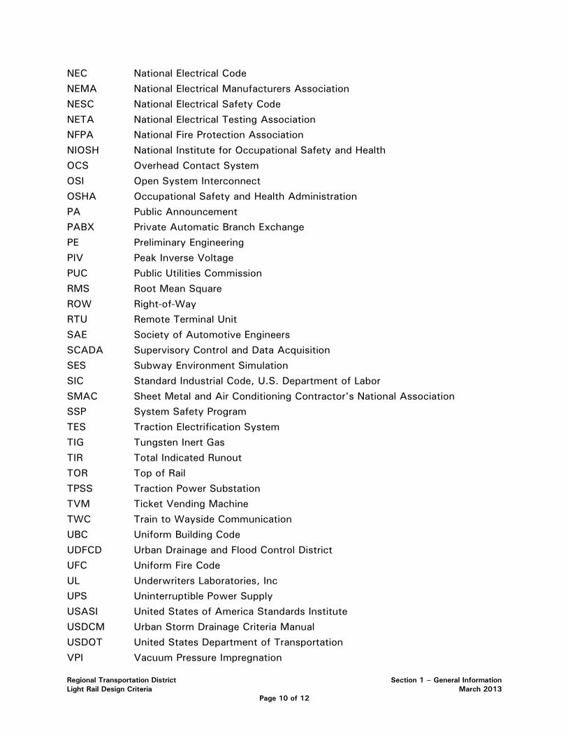
NEC National Electrical Code NEMA National Electrical Manufacturers Association NESC National Electrical Safety Code NETA National Electrical Testing Association NFPA National Fire Protection Association NIOSH National Institute for Occupational Safety and Health OCS Overhead Contact System OSI Open System Interconnect OSHA Occupational Safety and Health Administration PA Public Announcement PABX Private Automatic Branch Exchange PE Preliminary Engineering PIV Peak Inverse Voltage PUC Public Utilities Commission RMS Root Mean Square ROW Right-of-Way RTU Remote Terminal Unit SAE Society of Automotive Engineers SCADA Supervisory Control and Data Acquisition SES Subway Environment Simulation SIC Standard Industrial Code, U.S. Department of Labor SMAC Sheet Metal and Air Conditioning Contractor's National Association SSP System Safety Program TES Traction Electrification System TIG Tungsten Inert Gas TIR Total Indicated Runout TOR Top of Rail TPSS Traction Power Substation TVM Ticket Vending Machine TWC Train to Wayside Communication UBC Uniform Building Code UDFCD Urban Drainage and Flood Control District UFC Uniform Fire Code UL Underwriters Laboratories, Inc UPS Uninterruptible Power Supply USASI United States of America Standards Institute USDCM Urban Storm Drainage Criteria Manual USDOT United States Department of Transportation VPI Vacuum Pressure Impregnation

Regional Transportation District Section 1 – General Information Light Rail Design Criteria March 2013
Page 11 of 12
VSWR Voltage Standing Wave Ratio WB Wet Bulb
1.7 UNITS OF MEASURE
A Ampere Amp Ampere BTU British Thermal Unit CFS Cubic feet per second dB Decibel dBA Decibel on the 'A' weighted scale FC Foot-candles ft Foot or feet ft/min Foot per minute ft3/mi Cubic feet per minute (or cfm) ft3/sec Cubic feet per second (or cfs) g Acceleration due to Gravity (32.2 ft/s2 =9.81 m/s2 ) gpm Gallons per minute H Hour Hz Hertz In Inch J Joule kg Kilogram kHz Kilohertz km Kilometer km/h Kilometer per hour kWh Kilowatt hour I Liter Ib Pound Ibf Pound force m Meter MHz Mega Hertz mi Mile mph Miles per hour mphps Miles per hour per second min Minute mm Millimeter mV Millivolt µV Microvolt N Newton
Regional Transportation District Section 1 – General Information Light Rail Design Criteria March 2013
Page 12 of 12
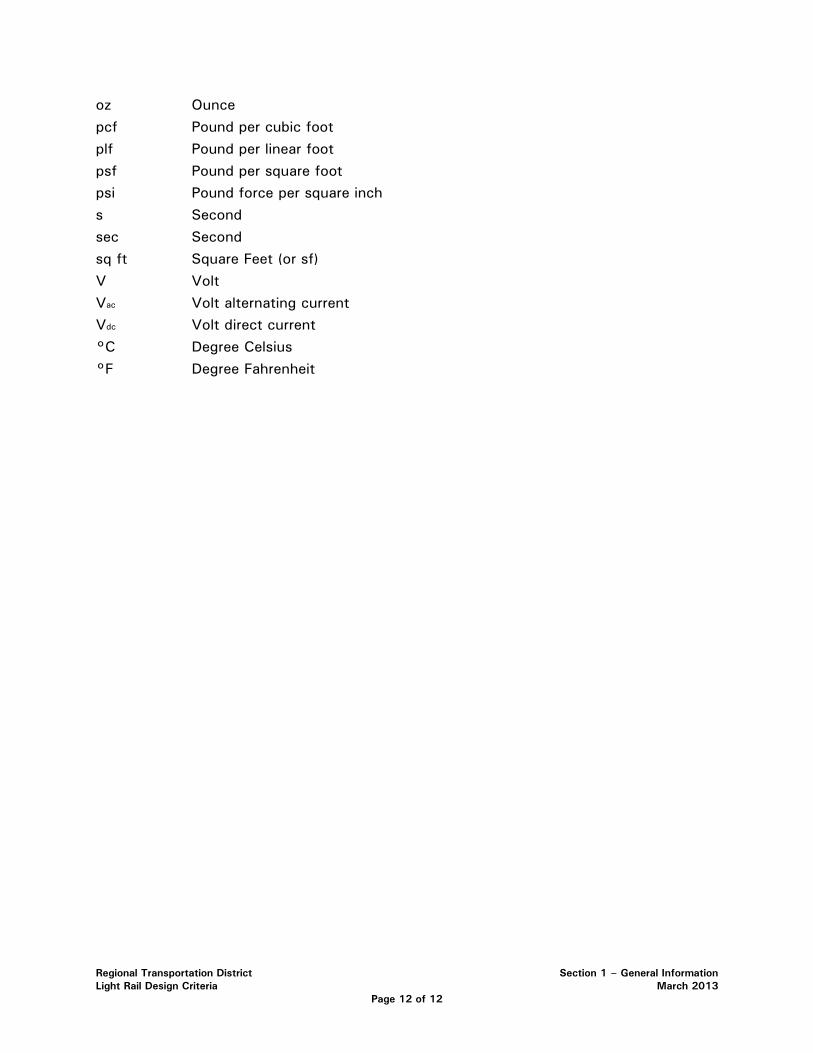
oz Ounce pcf Pound per cubic foot plf Pound per linear foot psf Pound per square foot psi Pound force per square inch s Second sec Second sq ft Square Feet (or sf) V Volt Vac Volt alternating current Vdc Volt direct current °C Degree Celsius °F Degree Fahrenheit
Regional Transportation District Section 2 - Operations Plan Light Rail Design Criteria March 2013
Page 1 of 7
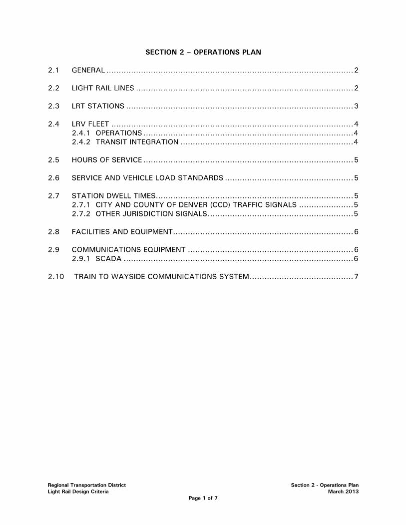
SECTION 2 – OPERATIONS PLAN 2.1 GENERAL .................................................................................................... 2 2.2 LIGHT RAIL LINES ........................................................................................ 2 2.3 LRT STATIONS ............................................................................................ 3 2.4 LRV FLEET .................................................................................................. 4
2.4.1 OPERATIONS ..................................................................................... 4 2.4.2 TRANSIT INTEGRATION ...................................................................... 4
2.5 HOURS OF SERVICE ..................................................................................... 5 2.6 SERVICE AND VEHICLE LOAD STANDARDS .................................................... 5 2.7 STATION DWELL TIMES ................................................................................ 5
2.7.1 CITY AND COUNTY OF DENVER (CCD) TRAFFIC SIGNALS ...................... 5 2.7.2 OTHER JURISDICTION SIGNALS ........................................................... 5
2.8 FACILITIES AND EQUIPMENT......................................................................... 6 2.9 COMMUNICATIONS EQUIPMENT ................................................................... 6
2.9.1 SCADA ............................................................................................. 6 2.10 TRAIN TO WAYSIDE COMMUNICATIONS SYSTEM .......................................... 7
Regional Transportation District Section 2 - Operations Plan Light Rail Design Criteria March 2013
Page 2 of 7
SECTION 2 - OPERATIONS PLAN
2.1 GENERAL
RTD’s objective is to operate all Commuter Rail (CR), Light Rail (LRT) and bus routes safely, reliably and efficiently and to integrate LRT operations with CR and bus service for the greatest convenience to the public. The LRT system is a means by which the integration of transportation services will assist the region in meeting clean air standards, alleviating traffic congestion and improving the overall quality of life in the area. RTD has two major goals:
• Provide improved transportation choices and options to the citizens of the District;
• Establish a proactive plan that balances transit needs with future regional growth.
Light Rail forms an integral part of RTD’s comprehensive transit program. Light Rail encompasses the Central Corridor, Southeast Corridor, Southwest Corridor and Central Platte Valley Extension. The most recent addition to RTD’s LRT system is the Southeast Corridor (T-REX), a 19 mile long extension of light rail originating at I-25/ Broadway Station and extending south along I-25 to Lincoln Avenue in northern Douglas County, with a spur on I-225 connecting from the light rail on I-25 to Parker Road. T-REX also includes highway and access improvements. This segment opened in November, 2006. Commuter Rail is the mode chosen for the North Metro, Northwest, East and Gold Line Corridors, all originating at Denver’s Union Station. Transfers at Union Station will be made to the three Light Rail (LRT) corridors. The updated FasTracks plan assumes full build-out of proposed rail lines by 2017, with improved service levels by the 2025 horizon year.
2.2 LIGHT RAIL LINES
The LRT is a conventional light rail transit system extending from 30th Avenue and Downing Street and Denver Union Station from the north to Littleton/Mineral Station on the south. Operations through downtown Denver are contra-flow relative to normal traffic, with trains heading northeasterly on California Street and southwesterly on Stout Street. The LRT provides direct connections between the light rail stations and Arapahoe Community College, Downtown Littleton, Englewood Civic Center, Broadway Marketplace, Auraria Campus, Colorado Convention Center, the 16th Street Mall, (Market Street Station and Civic Center Station), Five Points, the Auraria Administration Building, the Invesco Field at Mile High football stadium, Pepsi Center/Elitch Gardens with the terminus at Denver Union Terminal in Lower Downtown Denver. The latest expansion of Light Rail, T-REX opened November 17 2006, with 19 miles of new LRT track serving the Denver Technological Center as far south as Lincoln Avenue, with a spur running along I-225 to southeast Aurora at Parker Road and I-225.
Due to the complexities of a growing system, RTD introduced a letter and color designation for easier customer recognition. Currently the C Line (Orange) operates
Regional Transportation District Section 2 - Operations Plan Light Rail Design Criteria March 2013
Page 3 of 7
between Mineral Station and Denver Union Station. The D Line (Green) operates between Mineral Station and 30th/Downing Station with alternate weekday peak hour trips turning in downtown Denver on 19th St. Both lines operate on common track between Mineral Station and the Junction near Colfax Avenue. The C Line swings to the West and serves the Auraria Administration Building, Invesco Field at Mile High football stadium, Pepsi Center/ Elitch Gardens with the terminus at Denver Union Terminal in Lower Downtown Denver serving many thousands of sports and entertainment spectators attending events at Invesco Field, Pepsi Center, Coors Field and many major hotels and businesses in between. The D Line turns easterly at the Junction and northeasterly into central Downtown, and serves the Auraria Campus at the Colfax at Auraria Station, the Performing Arts Center and new Colorado Convention Center before bisecting downtown by running along California Street northbound, and Stout St. southbound conveniently serving the large employment population in Central Downtown and the Welton St. community. The E Line (purple) runs between Lincoln Avenue and Union Station on weekdays, terminating at Broadway and I-25 on weekends, where connections to Union Station are made via the C line. The F line (red) runs between Lincoln Avenue and 18th/California Streets, where connections to 30th/Downing can be made via the D Line. The H line (blue) connects the Nine Mile Park-‘n-Ride with 18th/California Street in Downtown Denver.
The Design Engineer shall coordinate with RTD specific requirements for future corridors which include pocket track, tail track, end of line geometries, maximum speed, consists, minimum headway and cross over locations. See Section 4.2.0 (RTD Trackwork) for information regarding the placement of crossovers for the maintenance of RTD light rail service during service disruptions or maintenance.
2.3 LRT STATIONS
As part of the initial LRT Central Corridor project, 14 passenger stations were constructed along the 5.3 mile corridor. A new station was added at 27th and Welton in late 1995. With the construction of the Southwest Corridor, an 8.7 mile extension to the Central Corridor, 5 new stations were added to the alignment in July 2000. The 1.8 mile Central Platte Valley extension, which opened in 2002, added 4 stations. The latest expansion of Light Rail, T-REX opened November 17 2006, with 19 miles of new LRT track and 13 more stations at Louisiana, University, Colorado, Yale, Southmoor, Belleview, Orchard, Arapahoe, Dry Creek, County Line, Lincoln, Dayton and Nine-Mile and all, but Louisiana Station, feature new or expanded park-n-rides providing 6,000 parking spaces along the corridor. An extensive bus feeder system makes it easy for people to get to and from all light rail stations. Bridges and underpasses provide pedestrian access to several of the stations. The West Corridor, currently under construction, will extend 12.1 miles from the Auraria West station and add stations at Federal Avenue, Perry Street, Knox Court, Sheridan Blvd., Lamar St., Wadsworth Blvd., Oak Street, Denver Federal Center, Red Rocks Community College and the Jefferson County Government Center in Golden. All station platforms are unattended and utilize automated fare machines for ticket sales and ticket validation. This self-service proof of payment system is monitored by Fare Inspectors and Security personnel. Platform security is provided by Light Rail Transportation Supervisors and local jurisdictional Police Departments, as part of their
Regional Transportation District Section 2 - Operations Plan Light Rail Design Criteria March 2013
Page 4 of 7
normal duties. Surveillance cameras are provided at all Light Rail Stations. A private contract security service also rides the trains and patrols all stations and park and rides.
2.4 LRV FLEET
Presently, RTD has a fleet of light rail vehicles (LRV) to service the Central, Southwest, and Central Platte Valley Corridors. Additional vehicles will be delivered between 2010 and 2013 for use on the Southeast and West Corridors. The LRV has 6-axles, is single-articulated, double-ended, and bi-directional. They are approximately 80 feet in length, 8 feet 9 inches in width, 13 feet high and weigh approximately forty (40) tons. These vehicles operate on a standard railroad track gauge of 4 feet 8 1/2 inches. They are powered from an overhead wire by 750VDC (nominal) direct current and capable of speeds up to 55 mph. Each vehicle can seat 64 passengers and will accommodate up to an additional 61 standing passengers at normal loads. Additional standees may be accommodated at a crush load capacity.
2.4.1 OPERATIONS
LRVs on the RTD alignment are operated manually. Automatic block wayside signals, traffic signals, radio communication, operational procedures and train orders govern operators regarding all movements of the vehicles. Appropriate street traffic signals, speed limit signage and wayside signals assist the operator in selecting proper movement sequence and speeds. Powered track switches are operated by operators via carborne equipment. All city street operations are by line of sight. City street crossings coordinate adjacent street intersection traffic signals. High speed grade crossings are protected using gate crossings with flashers and warning bells. Medians have also been installed at crossings to prevent traffic from driving around active gates. Gated crossings shall be monitored and recorded by video equipment. Multiple crossings are jointly used and maintained by the Union Pacific Railroad and RTD.
2.4.2 TRANSIT INTEGRATION
The system is operated by (RTD) as part of a fully integrated mass transit system which includes local bus routes, express bus routes, regional routes, shuttle bus routes and demand-response service for passengers with disabilities. RTD provides transit services to one of the largest geographical districts in the United States. RTD has a service area of approximately 2,400 square miles and serves the City and County of Denver and Broomfield, and all or portions of Adams, Arapahoe, Boulder, Jefferson and Douglas counties. RTD serves 38 municipalities within those 7 counties and operates 176 total fixed bus routes and 11 call-n-Rides. The service area population is 2.5 million. In 2003 the RTD fleet logged over 3 million hours of service with total annual boardings (including the Sixteenth Street Mall Shuttle, Light Rail and Access-a-Ride) of over 78.9 million. The size of the service area, population density, the nature of the roadway system and the development of suburban activity centers, has led to the creation of a
Regional Transportation District Section 2 - Operations Plan Light Rail Design Criteria March 2013
Page 5 of 7
system with a wide range of service types intended to most effectively serve this large and diverse region.
2.5 HOURS OF SERVICE
The LRT system operates in revenue service from approximately 3:30 a.m. to 2:15 a.m. on weekdays. On weekends, a late trip leaves from Union Station at 2:15 a.m. Departure of the first train of the day from the yard is prior to the 3:30 a.m. service start because of the travel time required between the yard and the first passenger station stop. This train will loop the system at reduced speed and will act as a sweep train, ensuring that the alignment is free of obstruction or other problems. The arrival of the last train into the yard will occur later than the scheduled revenue hours per day due to travel time from the last in-service station to the Light Rail Operations Facility.
2.6 SERVICE AND VEHICLE LOAD STANDARDS
Service standards include vehicle loading standards and service frequency, and establish criteria to determine the maximum level of crowding and service frequencies that a passenger would experience on the LRT system. The load standards established for RTD's light rail service are described below:
• Peak periods – 125 passengers per vehicle
• Off-peak periods – 64 passengers per vehicle (seated load)
• Special Events -- 180 passengers per vehicle (crush load)
2.7 STATION DWELL TIMES
Train dwell times at each passenger station are estimated to be 20 seconds on average, which allows sufficient time for normal boarding and exiting of passengers. At certain mixed traffic stations in the Denver CBD, additional dwell time is required for both large passenger loading and unloading as well as the need to adhere to the City Traffic Signal System. Adequate layovers at terminals for operators to use the restroom and switch vehicle ends are an essential part of the operating schedules.
2.7.1 CITY AND COUNTY OF DENVER (CCD) TRAFFIC SIGNALS
In May of 2011, CCD intends to adopt a 90-second light cycle throughout downtown Denver. This will support automobile and bus traffic flows and permit 4-car LRT operations and LRT contra-flows on California and Stout Streets.
2.7.2 OTHER JURISDICTION SIGNALS
The Design Engineer shall coordinate with RTD and other jurisdictions (Adams, Arapahoe, Denver, Douglas and Jefferson Counties and the cities of Aurora, Centennial, Denver, Englewood, Greenwood Village, Littleton, and Lone Tree) as necessary
Regional Transportation District Section 2 - Operations Plan Light Rail Design Criteria March 2013
Page 6 of 7
2.8 FACILITIES AND EQUIPMENT
These criteria will provide an overview of the facilities and equipment required to operate and maintain RTD’s LRT system.
2.9 COMMUNICATIONS EQUIPMENT
The key element of the communications system is the Supervisory and Control and Data Acquisition (SCADA) system and the radio. Each LRV operating cab and mobile units will have fixed mobile radios installed. In addition, all Train Operators, Light Rail Supervisors, Shop Supervisors and Maintenance of Way (MOW) employees working in the field will carry portable radios while on duty. Mobile and portable radios will provide two-way voice communications over channels designated for light rail use. The Operations channel will provide direct two-way communications between Central Control and all train operations personnel. A separate Maintenance channel may be utilized for communications between Maintenance personnel in the course of their activities and for exclusive use by operators/supervisors/maintenance personnel in moving vehicles during abnormal operations (dead car tow, foul weather, etc.) or other situations which may present a safety hazard.
In addition to the radio channel for Light Rail operations, a Commuter Rail channel, Bus Operations channel and Supervisors' channel may be utilized by Light Rail Operations for security or coordination with Bus Operations Dispatch whenever required.
Additional communication equipment includes:
• Emergency telephones are provided on some platforms for passenger use. Emergency phones autodial directly to RTD Safety and Security Operations and Control Center (OCC). Public pay telephones shall not be included on new platforms, but may be located near them. See Section 14 for emergency telephone requirements at new stations.
• Public Address (PA) equipment will be used for announcements on the LRVs, in the yard and the Maintenance shop.
• Automatic Vehicle Locator (AVL) will be utilized on LRVs and other mobile units as required.
• Public Address (PA) systems and variable message signs (VMS) will be utilized on selected platforms.
• Fax Machine: Central Control (located at the Mariposa facility) will utilize fax for receiving and sending information.
2.9.1 SCADA
The SCADA system provides for overall control and monitoring of traction power facilities, signals, station platform CCTV, ticket vending machines intrusion and fault alarms, station elevators, passenger information systems and security systems. Information and signals for the SCADA system are transmitted through fiber optic cables with communications houses located at various points along the ROW.

Regional Transportation District Section 2 - Operations Plan Light Rail Design Criteria March 2013
Page 7 of 7
2.10 TRAIN TO WAYSIDE COMMUNICATIONS SYSTEM
The train-to-wayside communication system will be used for providing routing wherever there are powered switches. The signals and switches on the operator's console provide the operator information regarding the status of the route and the ability to make changes in the switch positions. This is accomplished via street imbedded loops, interrogator equipment and carborne transponders. This enables the operator to make changes in the route quickly and safely thus enabling service schedule adherence in the event of abnormal operations. This same equipment may also be utilized in the build out of a rapid transit system to preempt traffic signals.
Regional Transportation District Section 3 – Civil Engineering Light Rail Design Criteria March 2013
Page 1 of 29
SECTION 3 – CIVIL ENGINEERING
3.1 CIVIL ENGINEERING ....................................................................... 2
3.2 CONTROL SURVEY ........................................................................ 2 3.2.1…HORIZONTAL CONTROL…… . …………………………………………2 3.2.2 VERTICAL CONTROL ........................................................... 2 3.3 CLEARANCES ............................................................................... 3 3.3.1 GENERAL ........................................................................... 3 3.4 STREET DESIGN ............................................................................ 3 3.4.1 GENERAL ........................................................................... 3 3.4.2 CLEARANCE TO LRT FACILITIES ........................................... 3 3.4.3 SIGNS, BOLLARDS, AND MARKERS ...................................... 4 3.4.4 PAVING ............................................................................. 4 3.4.5 TRAFFIC SIGNALS ............................................................... 4 3.4.6 AT GRADE CROSSINGS ....................................................... 4 3.4.7 SIGNAGE AND STRIPING ..................................................... 5 3.4.8 CURB RAMPS ..................................................................... 5 3.4.9 GUARDRAIL AND ROADSIDE BARRIERS ................................. 5 3.5 DRAINAGE .................................................................................... 6 3.5.1 GENERAL ........................................................................... 6 3.5.2 HYDROLOGIC CRITERIA ....................................................... 7 3.5.3 HYDRAULIC CRITERIA ......................................................... 8 3.5.4 BRIDGES/STRUCTURES ..................................................... 13 3.5.5 DETENTION FACILITIES ..................................................... 18 3.5.6 WATER QUALITY .............................................................. 18 3.5.7 EROSION CONTROL .......................................................... 18 3.5.8 STRAY CURRENT AND CORROSION CONTROL………….........19 3.5.9 EASEMENTS ..................................................................... 19 3.5.10 PERMITS .......................................................................... 20 3.5.11 VARIANCES TO CRITERIA..................................................20 3.6 UTILITIES ................................................................................... 21 3.6.1 INTRODUCTION ................................................................ 21 3.6.2 GENERAL LOCATION CRITERIA REQUIREMENTS ................... 21 3.6.3 GENERAL DESIGN CRITERIA REQUIREMENTS ....................... 23
Regional Transportation District Section 3 – Civil Engineering Light Rail Design Criteria March 2013
Page 2 of 29
SECTION 3.-.CIVIL ENGINEERING
CIVIL ENGINEERING 3.1
This section of the Light Rail design criteria establishes the minimum standards to be used in the design of the Civil Infrastructure supporting the Light Rail Transit (LRT) system. The criteria presented herein were developed considering safety, accepted engineering practices, and operation and maintenance of the LRT system.
LRT CONTROL SURVEY 3.2
HORIZONTAL CONTROL 3.2.1
The Horizontal Control for all alignments shall be based on the RTD FasTracks project datum using the Universal Transverse Mercator (UTM) North Zone 13. Units shall be converted from meters and reported in US Survey Feet (sft).
Project Units shall be modifies as follows:
UTM coordinates are converted from meters to US Survey Feet by the ratio of one meter equal to 3937 / 1200 feet multiplied by the scale factor of 1.000650402
Truncation applied to the coordinates shall be as listed below:
Northing – 14,000,000 sft
Easting – 1,000,000 sft
The minimum accuracy of survey work based on the control network shall be one part in 20,000 for linear measurements and 5 seconds per transit station for angular measurements. Legal descriptions of transit R.O.W. shall be tied into the established property lines of adjacent properties and on established section monumentation.
VERTICAL CONTROL 3.2.2
The Vertical Control for all projects shall be based on the North American Vertical Datum of 1988 (NAVD 88). Where the proposed work is to be in a certain relationship to an existing structure or facility, elevations of the existing structure or facility must be established by field survey and tied to existing benchmarks. Where the proposed LRT project is to be coordinated with other work, the relationship between the project datum and other working datums shall be established by field survey and tied to existing benchmarks. The error of closure in feet for establishment of vertical elevations shall not exceed 0.05√M, where M is the distance in miles.
Regional Transportation District Section 3 – Civil Engineering Light Rail Design Criteria March 2013
Page 3 of 29
CLEARANCES 3.3
GENERAL 3.3.1
Assurance of adequate and appropriate clearance for the passage of light rail vehicles (LRVs) throughout the mainline trackage, switches and special trackwork, stations, storage yards, and operations facilities is one of the most fundamental concerns inherent in the design process and must be rigorously monitored during the construction phase. Design criteria for clearances are complex and are based on numerous assumptions and interfaces.
The criteria developed in this manual apply to the design of the entire system. All designs shall meet the minimum clearances as specified in Sections 4 & 9 of this Design Criteria Manual.
STREET DESIGN 3.4
GENERAL 3.4.1
Necessary repair or replacement of existing roadways shall, at a minimum, provide services equivalent to the existing facilities. The costs associated with betterments to roadways shall be the responsibility of the facility owner. Unless otherwise specified, all road and street design for at-grade crossings, grade-separated crossings, and for other associated facilities should be in accordance with the current specifications and design guidelines of the local jurisdictions. Where the local jurisdictions have no design guidelines, the most current versions of the Colorado Department of Transportation (CDOT) Design Guide, and/or A Policy on Geometric Design of Highways and Streets (Green Book) by the American Association of State Highway and Transportation Officials (AASHTO) should be used.
CLEARANCE TO LRT FACILITIES 3.4.2
Where possible, the design of public streets adjacent to LRT facilities shall not preclude the construction of future LRT stations.
When the LRT corridor is located adjacent and parallel to roadway facilities, then clearances and requirements listed in, but not limited to, Section 4 – Track Work, Section 9 – Traction Electrification System, and Section 14 - System Safety and System Security of this Design Criteria shall apply.
Clearance height shall be in accordance with these Design Criteria, associated freight railroad, CDOT and local jurisdictional requirements.

Regional Transportation District Section 3 – Civil Engineering Light Rail Design Criteria March 2013
Page 4 of 29
SIGNS, BOLLARDS, AND MARKERS 3.4.3
Wherever practicable, all posts, pipes, signs, bollards, markers, and other small obstructions should be given a side clearance of at least 10 feet measured from track centerline and meet standards of local jurisdiction, AASHTO and MUTCD. Breakaway units shall be used where the installation is in a location exposed to traffic, except where the purpose is protection of passengers (e.g., at platform ends).
PAVING 3.4.4
Necessary repair or replacement of existing pavements shall, at a minimum, provide services equivalent to the existing facilities. All new pavements in public streets or highways shall be in conformance with the current specifications and practices of the roadway’s respective agency (i.e. local jurisdictions, CDOT, etc.). In a case where the local jurisdictions have no codes or standards, the CDOT Pavement Design Manual or the Metropolitan Government Pavement Engineering Council (MGPEC) standards shall be followed. Pavements on RTD facilities shall conform to the standards and specifications provided in the RTD Bus Transit Facility Design Manual.
TRAFFIC SIGNALS 3.4.5
CODES AND STANDARDS 3.4.5.1
All relocations, temporary or permanent, and restoration of traffic signal facilities shall be in accordance with the practices of the local jurisdictions. In the case where the local jurisdictions have no standards, the Manual on Uniform Traffic Control Devices (MUTCD) including the supplement by the State of Colorado, shall be followed.
NEW AND EXISTING SIGNAL INSTALLATIONS 3.4.5.2
New traffic signal installations shall provide for all required auto and pedestrian movements in addition to signal preemption that may be required for LRVs. All existing signals shall be modified to accommodate any revisions to auto and pedestrian movements and signal preemption for LRVs where required. All revisions shall be compatible with the local jurisdiction's traffic signal control program.
AT GRADE CROSSINGS 3.4.6
The design of at-grade crossings shall conform to the most recent edition of the MUTCD, and shall be approved by the Colorado Public Utilities Commission (PUC) and the jurisdiction with authority for the cross street. See Section 3.4.10 Public Utilities Commission (PUC) Approvals for LRT Crossings and Section 4.4.17 Grade Crossings.
Regional Transportation District Section 3 – Civil Engineering Light Rail Design Criteria March 2013
Page 5 of 29
SIGNAGE AND STRIPING 3.4.7
All signage and striping in public areas shall conform to the current specifications and practices of the local jurisdictions. Where the local jurisdictions have no standards, the MUTCD (as supplemented by the State of Colorado) shall be followed.
CURB RAMPS AND CURB CUTS 3.4.8
The Design Engineer shall obtain approval from the local jurisdiction or proper authority for the geometry and locations of curb cuts.
The design of curb cuts and curb ramps shall be in strict accordance with the applicable provisions of the Americans with Disabilities Act Accessibility Guidelines for Buildings and Facilities (ADAAG).
Curb cuts are to be included when curbs in public space are constructed or restored as part of the LRT Project.
Walkway, highblock and structural access ramps shall not exceed 4.75%.
GUARDRAIL AND ROADSIDE BARRIERS 3.4.9
Where required, guardrail, roadside barriers (e.g. type 7 concrete or other type as approved by RTD) and appropriate attenuators shall meet the requirements and details of the CDOT Standard Specifications for Road and Bridge Construction and Standard Plans, M & S Standards, current edition. Guardrail and roadside barrier placement in conjunction with clear zone provisions should follow the guidelines of the AASHTO Roadside Design Guide.
See Section 14 for additional discussion on right-of-way fencing and barriers.
PUBLIC UTILITIES COMMISSION (PUC) APPROVALS FOR 3.4.9.1LRT CROSSINGS
The construction, operation and maintenance of the LRT, as it crosses at, above, or below any “public highway” (which term shall be interpreted to include pedestrian walkways, bicycle paths, equestrian trails, and roadways for motor vehicles, as well as overcrossings and undercrossings of the same), are subject to approval by the PUC pursuant to Section 40-4-106, Colorado Revised Statutes (C.R.S.). In order to expedite the issuance of such approval a General Concept Application shall be prepared of those anticipated LRT/public highway crossings and submitted to the PUC for approval. LRT crossing analysis for PUC approval shall include but not limited to the following:
• Gated crossings
Regional Transportation District Section 3 – Civil Engineering Light Rail Design Criteria March 2013
Page 6 of 29
• Track signalization implementation and supporting data
• Cross-sections
• Warning devices
• Submittal chain
• Traffic study/analysis
In addition the General Concept Application shall include but not be limited to the following:
• Plan Drawing showing the public crossing of the LRT alignment
• Property owners and their legal addresses on all four corners affected by the public/LRT crossing
• An elevation drawing showing the proposed horizontal and vertical clearances of the LRT envelope with the public crossing for both at-grade and grade-separated crossings, which includes, but is not limited to, street crossings, cross sections and clearance envelopes.
• If the crossing includes any structures, details of the type of structure shall be included in both the plan view and elevation views
DRAINAGE 3.5
GENERAL 3.5.1
This section provides standards for the design of drainage facilities associated with the LRT infrastructure and systems impacted by development of new LRT systems. Drainage features may include storm sewer, cross-culverts, and/or open channels. Such features may serve the LRT, adjacent properties, and/or may be a part of a regional drainage system.
The purpose of drainage facilities associated with LRT and the goal of the LRT drainage Design Engineer is to protect the LRT infrastructure, protect public safety, and to protect other public and private property from damage caused by flooding. All signal, OCS equipment, TES equipment and communication equipment shall be protected from major storm events. Such protection shall be provided in accordance with locally and regionally accepted engineering standards and practices, as modified for LRT by the standards presented in this Design Criteria Manual.
Regional Transportation District Section 3 – Civil Engineering Light Rail Design Criteria March 2013
Page 7 of 29
Facilities placed within RTD-owned LRT right-of-way shall conform to the standards provided in the latest edition of the AREMA Manual of Railway Engineering (Manual). Facilities to be placed within right-of-way that is owned by an entity other than RTD (BNSF, UPRR, or other entity) shall be designed to the standards of that entity.
The hydrologic and hydraulic design of facilities shall be in accordance with the criteria of the agency in whose jurisdiction each project or section of project is located. For work located within or adjacent to CDOT right-of-way, CDOT standards as specified in the latest edition of the CDOT Drainage Design Manual shall be followed. If local jurisdictions do not have applicable criteria or standards, the designer shall use the design standards and technical criteria presented in the latest editions of the Urban Drainage and Flood Control District Urban Storm Drainage Criteria Manual (UDFCD USDCM) Volumes 1, 2, and 3, and the CDOT Drainage Design Manual. Facility design shall be coordinated with local jurisdictions.
HYDROLOGIC CRITERIA 3.5.2
Unless otherwise noted, hydrologic criteria used in design of LRT facilities shall be in accordance with the Urban Drainage and Flood Control District’s Urban Storm Drainage Criteria Manual (UDFCD USDCM).
MINOR AND MAJOR STORM DRAINAGE FACILITIES 3.5.2.1
The minor storm drainage system transports runoff from minor frequency storm events with minimum disruption to the urban environment. The minor storm may be conveyed in curb and gutter, ditches and storm sewer. The 5-year event shall be the minor design storm for LRT facilities.
The major storm drainage system shall be designed to convey runoff from the 100-year frequency storm event to minimize health and life hazards, damage to structures and interruption of services.
LRT and appurtenant facilities shall be designed for both recurrence intervals with the following criteria:
• LRT drainage facilities shall be designed to protect the LRT system during the major storm. Storm sewer systems shall be designed to protect all parts of LRT trackway, and LRT stations from flooding at all times. LRT trackway and station platforms shall not be located in a 100-year floodplain, and conveyance systems adjacent to LRT trackway shall be designed so that the ballast and sub-ballast shall be above the hydraulic grade line (HGL) during a 100-year event. The LRT trackway (including paved sections) shall not be used for conveyance of stormwater.
Regional Transportation District Section 3 – Civil Engineering Light Rail Design Criteria March 2013
Page 8 of 29
• For facilities appurtenant to the LRT, including roadway improvements and parking lots, the minor storm system shall be designed for the 5-year recurrence interval storm. The major storm system shall be designed for the 100-year recurrence interval storm. Park-n-Ride facilities are addressed in the RTD Bus Transit Facility Design Manual.
RUNOFF 3.5.2.2
Design peak runoff rates shall be determined using methods specified by the criteria of the local jurisdiction. If a method is not specified by the local jurisdiction, the Rational Method or the Colorado Urban Hydrograph Procedure (CUHP) and Storm Water Management Model (SWMM) as presented in the UDFCD USDCM shall be used, as applicable. Peak runoff rates may also be obtained from reports published by the local jurisdiction, UDFCD, CWCB, CDOT, or FEMA as appropriate to the specific drainage facility or drainageway. All runoff from proposed facilities shall be discharged in a manner similar to existing conditions in both location and quantity.
FEDERAL EMERGENCY MANAGEMENT ASSOCIATION 3.5.2.3(FEMA) REGULATORY FLOODPLAINS
Facilities that cross, are located within, or are adjacent to a FEMA-regulated flood zone (Zone AE, etc.) shall use FEMA jurisdictional flows for facility design. Facilities shall be designed in accordance with the floodplain ordinance of the local drainage authority. The design shall include preparation and submittal of CLOMR and LOMR documentation, if required.
HYDRAULIC CRITERIA 3.5.3
All storm sewer, hydraulic structures, and appurtenances shall be designed in accordance with the design standards and technical criteria of the local jurisdiction, as modified below:
• Drainage design shall consider areas adjacent to the tracks where elements such as streets, parking facilities, roads, landscaping, walls, etc. may have an impact on the drainage of the trackway area.
• Special attention shall be directed to providing drainage in all track areas. Ditches, grated inlets, curb and gutter, storm sewers, and/or underdrains shall be provided at the edges of the track to prevent water from ponding or covering any part of the track structure, or contributing to subgrade instability. Trackside ditches shall be provided wherever possible. Minimum ditch grades shall be 0.3% or as approved by RTD
Regional Transportation District Section 3 – Civil Engineering Light Rail Design Criteria March 2013
Page 9 of 29
based on soil conditions, flow rates, vegetative cover, and proximity to RTD facilities.
DESIGN STORMS 3.5.3.1
Facilities shall be designed to convey peak flows for the design storm frequencies discussed in Section 3.5.2.
REPLACEMENT OF EXISTING FACILITIES 3.5.3.2
Necessary replacement of existing storm drainage facilities shall, at a minimum, provide services equivalent to the existing facilities. New facilities shall be designed in accordance with the current design standards of the jurisdictional authority. Services to adjoining properties shall be maintained at all times during construction.
LRT TRACKWAY 3.5.3.3
Wherever possible, ditches shall be located parallel to the trackway to convey trackway drainage and to intercept runoff entering the right-of-way.
Stormwater runoff from off-site areas shall be intercepted and conveyed out of the ROW in ditches and storm sewer, and shall not be conveyed in trackway underdrains. Trackway (open ballast or paved) shall not be used for conveyance of stormwater.
The designer shall check the hydraulics of ditches adjacent to the trackway to confirm that the 100-year HGL will not be above the top of subgrade during the peak 100-year runoff. Where the LRT operates on, or shares right-of-way with freight rail trackage, the design requirements of the dominant railroad shall be used, if more conservative than the standards presented in this section.
STORM SEWER 3.5.3.4
Design and construction of all storm sewer facilities constructed within the LRT right-of-way shall conform to the requirements of the latest edition of the AREMA Manual for Railway Engineering. All storm sewer pipe shall be Class V, gasketted, RCP with a minimum pipe diameter of 15 inches. Plastic and metal pipe shall not be used without RTD approval. Variances shall be based, in part, upon the ability of the material to withstand desired loading and to resist corrosion due to stray current.
Storm sewer constructed outside of the LRT right-of-way shall be constructed with Class III or better gasketed, RCP. Storm sewer shall be placed with a minimum clearance of 5 feet from bottom of rail (BOR) to top of pipe unless otherwise approved by RTD. The 100-year energy

Regional Transportation District Section 3 – Civil Engineering Light Rail Design Criteria March 2013
Page 10 of 29
grade line (EGL) in the storm sewer system shall be below the top of subgrade. The Design Engineer shall include EGLs/HGLs on all storm sewer and ditch profiles.
Cross-culverts and storm sewer under the LRT trackway shall cross at a 90-degree angle to the tracks whenever possible and have a maximum headwater to depth ratio of 1.5. The EGL in cross-culverts shall be below the top of subgrade for all areas adjacent to the trackway.
Storm sewer structures including manholes, junction boxes, inlets, vaults, or other structures shall be placed outside of the LRT right-of-way if possible. If located within LRT right-of-way, such structures shall be designed in conformance with AREMA standards. Any structures that vary from agency standards shall be subject to acceptance by RTD for maintenance. For storm sewer construction through contaminated subsurface materials, consideration shall be given to pipe design features, such as a pipe lining system, to eliminate infiltration of contaminated groundwater into the storm pipe.
Storm drainage facilities for the LRT shall be designed for an expected functional life of 50 years as a minimum.
INLETS 3.5.3.5
All inlets within the LRT trackway shall be RTD Standard Ballast Inlet.). Where ballast inlets are not functional and as approved by RTD, custom inlet boxes and grates may be designed to fit non-standard conditions. Inlets within the LRT trackway shall be designed for LRT loading. Inlets shall not be placed in paved trackway adjacent to station platforms or in at-grade crossings. Flangeway drains or trench drains shall not be used within paved trackway unless approved by RTD.
Inlet grates located within the LRT trackway shall be designed to prevent ballast rock from passing into the storm sewer system. Inlets located directly adjacent to the trackway shall be designed with a ballast retaining wall between the inlet and the track, or shall be constructed with ballast-proof grates.
Inlet grates in pedestrian areas shall be heel-proof and non-slip. Bicycle-safe grates are required at all locations subject to bicycle traffic.
Inlets shall be located in sumps rather than on grade wherever possible. Within confined areas along the alignment, inlets shall be located at the low points. All inlets and manholes along the alignment shall be identified on drawings by project stationing.

Regional Transportation District Section 3 – Civil Engineering Light Rail Design Criteria March 2013
Page 11 of 29
UNDERDRAINS 3.5.3.6
Underdrains, also referred to as Subdrains, shall be designed and constructed in accordance with the latest edition of the AREMA Manual for Railway Engineering, Volume 1, Chapter 1, or as modified in these design criteria. Where right-of-way constraints do not allow use of the standard ditch section or where the track structure is supported by wall systems, underdrains shall be used. The engineer shall size underdrains based on a hydrologic and hydraulic analysis of the local trackway drainage only. Underdrains are intended to collect and convey natural stormwater from the trackway facility only and shall not be allowed to collect off-site water, water from adjacent or overhead structures, or allow other structures to plumb into underdrains or ballast inlets. It is the Design Engineers responsibility to drain the trackway structure and to not induce additional waters into the underdrain system.
Underdrain pipes and cleanouts shall be designed for the anticipated loading conditions for both the final constructed condition and for the during constructed condition including, but not limited to, LRT vehicle live load, freight rail live load, construction vehicle loading, soil / ballast dead load, and all other anticipated loadings to prevent pipe collapse and failure.
Underdrain and cleanout pipe material shall be made from the same material and shall be either of the following:
• HDPE: Perforated (underdrain only), dual wall, HDPE pipe with bell and spigot joints meeting AASHTO M252, ASTM F2648, AASHTO M294, or ASTM F2306 requirements. Pipe joints and fittings shall be gasketed, soil tight, and meet the requirements of ASTM D3212 (joints) and ASTM F477(gaskets). Gaskets shall be installed by the manufacturer with a removable wrap to ensure gasket is clean and free from debris. Joints may be lubricated and shall be assembled per the manufacturers recommendations. Pipe shall be provided in straight segments. Cleanout pipe shall be non-perforated. Coiled pipe will not be allowed.
• PVC: Perforated (underdrain only), corrugated PVC pipe with gasketed, bell and spigot joints meeting ASTM F949 requirements. Gaskets shall be installed by the manufacturer with a removable wrap to ensure gasket is clean and free from debris. Joints may be lubricated and shall be assembled per the manufacturer’s recommendations. Pipe shall be provided in straight segments. Cleanout pipe shall be non-perforated. Coiled pipe will not be allowed.
Regional Transportation District Section 3 – Civil Engineering Light Rail Design Criteria March 2013
Page 12 of 29
Cleanouts shall consist of providing a ground level access point to the underdrain piping system to allow video inspection and maintenance. Cleanout pipe shall be 10” inside diameter, non-perforated pipe. The cleanout shall be installed with a 45 degree manufactured wye connection at the underdrain that is orientated with the cleanout directed down slope with the underdrain. Cleanouts shall be provided with a maximum spacing of 150 feet between cleanouts or alternate underdrain access points and at the ends of the underdrain systems. The cleanout opening at the surface shall be set perpendicular to the nominal surface grade with the top of the cleanout set 2 inches +/- above the nominal surface grade to prevent ballast from covering the cleanout pipe. The cleanout opening shall be covered with an approved cast iron frame and solid cover as shown in the standard detail to prevent debris and sedminet from entering the underdrain system. A concrete collar shall be installed surrounding the pipe cleanout.
Where bell and spigot joints are not applicable, butt welds or splicing collars shall be used to joint cut pipe to meet the lengths needed or to splice and repair pipe. Butt welds and splicing collars shall be installed per manufacturer recommendations with manufacturer approved materials.
• Underdrain pipe shall be surrounded by a minimum 4 inches of washed, well graded, granular crushed rock or gravel drainage material, and the pipe crown placed below the bottom of the subballast with perforations located along invert of pipe. The underdrain systems shall be wrapped with a filter fabric (minimum weight 4 ounces per square yard) by placing the fabric between the gravel drain material and the subgrade. Underdrain clean outs, pipes, and culverts shall be designed and located to facilitate maintenance and to reduce the possibility of becoming clogged. See Figures for placement of the underdrain. Underdrains shall be a minimum of 6 inches in diameter and shall be hydraulically designed to assure proper pipe size and to maintain the HGL below the ¾ full depth. Underdrains shall have a positive downward slope at all locations and pipe slopes and key invert elevations at pipe ends, cleanouts, ballast inlets, outfall locations, changes in grade, etc. shall be shown on the plans. Where underdrain system profiles will be different than their respective track system profiles, an underdrain pipe profile shall be provided in construction documents.
The designer shall check the hydraulic grade line (HGL) of the system where the underdrain outfalls to confirm that the 100-year HGL of the downstream system will not allow the introduction of stormwater into the trackway subgrade through the underdrain system. Flap
Regional Transportation District Section 3 – Civil Engineering Light Rail Design Criteria March 2013
Page 13 of 29
gates shall not be used in the LRT storm sewer system where underdrains are installed.
Underdrain systems constructed for the purpose of intercepting groundwater, other than from stormwater from the track drainage basin, shall not be connected to the storm sewer system unless approved by RTD. For the purpose of intercepting and conveying groundwater, underdrains shall discharge to and be conveyed in a separate system to a location where treatment can take place; if required.
STATION PLATFORMS 3.5.3.7
The designer shall minimize the amount of offsite runoff entering trackway in station areas, slope platform away from trackway, where practical, and within RTD ROW, and avoid placing inlets within station platforms. Inlets that are located within platform areas shall be constructed for HS-20 loading and shall be installed with pedestrian friendly, heel-proof grates.
PARK-N-RIDES 3.5.3.8
See the RTD Bus Transit Facility Design Criteria manual for park-n-Ride drainage design standards.
RAIL EMBANKMENT EDGE TREATMENT 3.5.3.9
In areas where more than 50 feet of trackbed width contributes runoff to a fill slope, where the fill slope is steeper than 4:1, or where concentrated flow from underdrains, deck drains, or storm sewers are discharged, runoff shall be collected and conveyed from the top of the slope to inlets or rundowns to prevent erosion of the embankment.
BRIDGES/STRUCTURES 3.5.4
RETAINING WALLS 3.5.4.1
Retaining wall drainage shall be coordinated with the retaining wall structural designer. Runoff from slopes above retaining walls including concentrated flows shall not be allowed to discharge behind any retaining wall or pass over the top of any retaining wall. Such flows shall instead be intercepted and conveyed by concrete channel or pipe down to grade or to inlet before reaching the wall.
Underdrains shall be provided adjacent to track supported on walls.
Regional Transportation District Section 3 – Civil Engineering Light Rail Design Criteria March 2013
Page 14 of 29
BRIDGES 3.5.4.2
Bridge deck drainage shall be in accordance with this design criteria, the criteria presented in the CDOT Bridge Design Manual, Subsection 16.1, and the FHWA publication HEC-21, Design of Bridge Deck Drainage.
Drainage of elevated LRT bridges from the deck down to the local system shall be conveyed to an approved point of discharge, which may include storm sewer, ditch, channels, or other approved conveyance system.
Drainage not associated with the bridge structure shall be collected and directed away from the bridge, joints, footings, piers and abutments. A bridge end drainage system is required to intercept drainage on each end of the bridge prior to drainage entering the bridge deck.
All bridge structures shall have a deck drainage system designed for the 100-year storm event with 100% capture by inlets or trench drains with end dams at bridge ends and all joint locations. No drainage will be allowed to cross bridge joint or off ends of bridge. Direct fixation bridges shall be designed with a maximum water depth of 2 inches at any location on the deck. The designer shall consider the use of trench drains at the ends of all direct-fixation bridges. The use of trench drains at the ends of direct-fixation bridges shall be evaluated on a case by case basis and approved by RTD.
The designer shall coordinate with the bridge structural engineer and consider the drainage system layout, inlet and piping locations, and pipe outlet locations early in the design process since these items may impact the design of key structural elements. Drainage that does not originate from the bridge structure shall not be allowed to drain on to the bridge structure or tie into the bridge structure deck drainage system.
The deck drainage system, including inlets, pipes, cleanouts, and pipe outlets, shall be shown on the plans and located using station / offsets, northing / easting, or dimensions. The plans are to show details relating to inlet placement and attachment to the bridge, piping layout, modifications to the structure associated with inlet and pipe penetrations and fastener locations. Any structural elements that are impacted due to the drainage system shall be structurally designed and detailed on the plans.
Drainage from bridge structures shall not outlet, drip, or in any way drain onto girders, flanges, bearings, pier caps, abutment caps, pier or abutment walls or footings, roadways, sidewalks, railroad tracks, pedestrian paths and walkways, maintenance paths, retaining walls,
Regional Transportation District Section 3 – Civil Engineering Light Rail Design Criteria March 2013
Page 15 of 29
behind retaining walls, slope paving (unless properly designed), or unprotected slopes.
Downspouts shall be galvanized steel pipe 10-inch minimum diameter for bridge drains and shall meet the requirements of ASTM A53; they shall be standard weight (Sch. 40). Downspout pipe shall be hot dipped galvanized after fabrication. Galvanizing shall meet the requirements of AASHTO M111. Gray iron castings shall conform to the requirements of AASHTO M105, class 30. Ductile iron castings shall conform to the requirements of ASTM A536. Grade shall be optional unless otherwise designated. Structural steel shall conform to the requirements of AASHTO M183. Cleanouts shall be provided for downspout systems in a manner as to provide access to all parts of the deck drainage system.
The drainage outlet or discharge end of the pipe system shall be allowed to freely drain and shall not be directly connected to a storm sewer system, without prior approval from RTD. The drainage outlet shall be located between 6” and 1’ above the finished grade, erosion protection, or a stormwater inlet grate. Discharge from drain pipes with a high exit velocity can cause erosion. To prevent erosion, the designer shall include erosion protection at each discharge point, which includes utilizing concrete splash blocks, riprap revetment, grouted riprap, soil riprap, or concrete pans with curbs. Erosion protection measures shall be designed from the drainage outlet to a downstream receiving point and assure erosion protection along the entire flow path. Where this is not possible or is impractical, the designer shall locate and size the erosion protection to slow the water discharge velocity onto adjacent native grade to a level below the erosive threshold of the soil.
BRIDGES / LARGE CULVERTS OVER DRAINAGEWAYS 3.5.4.3
Bridges and large culverts over waterways (ie., culverts with a span length measured along the centerline of track or roadway of 10 ft or greater) shall be evaluated to determine the hydraulic performance at, as a minimum, the 50-year and 100-year storm events and determine the structures scour condition and general stability in the stream environment.
Hydraulic design criteria shall include the criteria listed in this design manual, the latest version of the CDOT Drainage Design Manual, and the associated freight rail company’s hydraulic criteria. Criteria will depend on the bridge location, adjacent structures, and review agency requirements. Where criteria are in conflict, the stricter of the criteria shall apply.
Bridges and large culverts shall be analyzed using the latest version of the US Army Corps of Engineers HEC-RAS computer model or other commonly used computer model as approved by RTD. A hydraulic
Regional Transportation District Section 3 – Civil Engineering Light Rail Design Criteria March 2013
Page 16 of 29
analysis shall include, as a minimum, an existing conditions analysis and a proposed conditions analysis. Additional analysis may be required to meet Federal Emergency Management Agency (FEMA) requirements.
Hydraulic criteria for bridges supporting LRT facilities are as follows:
• 50-year water surface elevation shall be below the low chord or lowest point on the superstructure.
• 100-year energy grade line shall be below the top of subgrade. Subgrade shall be known as part of the track design, surveyed in on existing bridges, or assumed to be 2 feet below top of rail.
• Where practical, the 100-year water surface elevation shall be below the low chord or lowest point on the bridge plus freeboard as required by the CDOT Drainage Design Manual. Freeboard requirements shall be subject to approval by RTD.
• New bridges shall be sized to limit the velocity through the bridge opening to approximately 7 feet per second in a subcritical condition or as required by RTD.
Hydraulic criteria for large culverts under LRT facilities are as follows:
• 50-year and 100-year water surface elevation shall be below the top of the inside of the pipe or box. At no location under the tracks or RTD right-of-way shall the culvert be in pressurized flow.
• 100-year energy grade line shall be below the top of subgrade. Subgrade shall be known as part of the track design, surveyed in on existing bridges, or assumed to be 2 feet below top of rail.
• New culverts shall be sized with a maximum outlet velocity of 10 feet per second at the end of the culvert barrel. Concrete headwall, wingwalls, and apron or other structure may be required to reduce the downstream velocity prior to water exiting into the natural channel. At no point in the structure shall the interior velocity be greater than 17 feet per second due to concrete erosion.
• Where practical, new large culverts shall be designed to prevent pressurized flow from occurring during the 100-year event (H/D < 1) under RTD right of way.
Regional Transportation District Section 3 – Civil Engineering Light Rail Design Criteria March 2013
Page 17 of 29
• Where practical, culvert barrels shall be orientated to align the outlet flow with the channel flow path and not require flow to make a sharp bend into a channel.
Existing bridges, especially those located on existing and former freight rail lines, shall be evaluated to determine whether the structure acts as an individual hydraulic structure or as a component to a multi-opening hydraulic system that may include 2 or more drainage structures along the same line acting as a unit. If it is believed that the structure is part of a multi-opening system, RTD shall be contacted prior to the beginning of any detailed analysis.
Existing bridges that are shown to be overtopped during a 100-year event shall be evaluated to determine the cause of the overtopping (ie., structure too small, track grade too low, tailwater condition too high, etc.) and a recommendation prepared and presented to RTD for review. If overtopping cannot be eliminated or is not feasible, the designer shall coordinate with the structural engineer to help identify structure options that will with stand overtopping conditions with minimal damage.
New bridges and culverts shall be designed with substructures and culvert barrels orientated perpendicular to the tracks under the LRT and any adjacent rail trackways.
New and existing bridges shall be evaluated for stream stability and scour in accordance with the Federal Highways Administration Hydraulic Engineering Circulars HEC-18 and HEC-20. Field inspections of scour conditions and stream stability shall be conducted on a bi-annual basis along with the regular bridge inspection schedule. Structures found to have special concerns shall be field inspected on an annual basis. If existing bridges are determined to be scour critical, the designer shall review the site and stream conditions, review UDFCD planning studies for possible future channel improvements, develop a series of options to mitigate or monitor the scour critical condition, and present options to RTD engineering, maintenance of way, and management staff for evaluation and consideration. Mitigation options may include stream countermeasures designed in accordance with the Federal Highways Administration Hydraulic Engineering Circular HEC-23, UDFCD USDCM, or other credible sources. Large culverts shall be evaluated for scour / erosion at the ends of the barrel or aprons where the structure transitions into the natural channel.
New bridges shall be designed to meet the design criteria without overtopping. New bridges shall be designed to minimize scour. Bridges and structures crossing FEMA-regulated floodplains shall be

Regional Transportation District Section 3 – Civil Engineering Light Rail Design Criteria March 2013
Page 18 of 29
designed to minimize impacts to the floodplain and any impacts shall be within allowable FEMA floodplain and local requirement limits. Bridges and structures crossing waterways that are not FEMA-regulated shall be designed to meet local floodplain criteria and to minimize impacts as compared to existing condition hydraulic models to prevent impacts to upstream and downstream properties. RTD shall be notified of any property impacts or increases in water surface elevation for the 100-year event that are above the comparable existing condition water surface elevation.
DETENTION FACILITIES 3.5.5
If required by the local jurisdiction, detention facilities shall be provided in accordance with local criteria. Underground detention shall not be used unless approved by RTD.
WATER QUALITY 3.5.6
Water quality facilities shall be provided for park-n-ride and station facilities if required by the local jurisdiction. Water quality facilities shall be designed with consideration for ease of long-term maintenance. Underground facilities (such as water quality vaults and inlets) shall not be used unless approved by RTD and allowed by local jurisdiction. Water quality facilities shall be designed to comply with RTD’s Light Rail Corridor Storm Water Management Program and be in compliance with RTD’s Municipal Stormwater Permit (MS4).
PUMP STATIONS 3.5.7
The use of pumping stations shall not be permitted unless approved by RTD, and shall be used only where storm water removal by other means is not feasible. Pump stations shall be designed to protect LRT facilities in accordance with the criteria presented in Section 3.5.2 of this Design Criteria. The FHWA publication Highway Stormwater Pump Station Design (Hydraulic Engineering Circular 24) shall be used for pump station design. The extent of the 100-year storm shall be determined and safeguards against flooding shall be provided.
A storage reservoir shall be incorporated with the pump station design. The maximum water level in storage shall be more than 2 feet below the lowest grate elevation in the tributary system. The configuration shall provide for screening out debris and a minimum of 3 pumps. Pump equipment and controls shall be explosion proof, corrosion resistant and appropriate for the application. Backup systems for power, control and pumping shall be provided.
The design shall include access for ordinary maintenance, including provisions for replacing pumps. The pump house shall have locked doors,
Regional Transportation District Section 3 – Civil Engineering Light Rail Design Criteria March 2013
Page 19 of 29
fence and gate for security and an adequate ventilation system. The design shall eliminate the need for confined space entry as defined by OSHA and NIOSH where possible. The site layout shall address mitigation of aesthetics and noise. The installed equipment shall be certified and tested prior to acceptance. Operation and maintenance manuals for the facility shall be provided by the Contractor.
Pump station equipment shall be connected to RTD’s SCADA system.
EROSION CONTROL 3.5.8
The designer shall prepare erosion control plans following local jurisdiction standard Best Management Practices (BMP)for the completed project condition. If the local jurisdiction has no design standards, plans shall be prepared in accordance with UDFCD USDCM Volume 3 or as directed by RTD. These plans will be provided to the construction contractor for their use.
The construction contractor shall prepare erosion control plans and Storm Water Management Plans (SWMPs) for various phases of construction and for the completed project, or as required by the local jurisdiction, meeting the local jurisdiction’s requirements and BMP. The construction contractor is responsible for obtaining permits may utilize the designers erosion control plans as the basis for preparing the plans required for permits and inspections. Erosion control and/or SWMP plans shall meet the requirements of the local jurisdiction and the State of Colorado Department of Public Health and Environment (CDPHE) requirements. The LRT construction contractor shall be responsible for obtaining local permits and coverage under the CDPHE Stormwater General Permit for Construction Activities.
All erosion control shall comply with the conditions of the current version of the RTD’s Light Rail Corridor Stormwater Management Program and RTD MS4 permit.
STRAY CURRENT AND CORROSION CONTROL 3.5.9
Methods and materials for soil corrosion control, stray current corrosion control, as well as barrier coating and sealants shall be considered and applied as required in Section 10 – Stray Current/Corrosion Control. This includes backfill, buried piping and concrete, reinforced concrete retaining walls and other underground structures and casings. Quality Control testing shall be done as shown Section 10
EASEMENTS 3.5.9.1
All storm sewers crossing the LRT right-of-way that serve upstream properties shall become the ownership of the local jurisdiction. Where such

Regional Transportation District Section 3 – Civil Engineering Light Rail Design Criteria March 2013
Page 20 of 29
storm sewer facilities are located outside of public right-of-way, license agreements shall be prepared for the conduit crossing.
The designer shall identify any temporary or permanent easements required to construct and maintain storm water drainage facilities, and shall coordinate with RTD’s Property Management Division to prepare any required agreements.
PERMITS 3.5.10
404 Permit - Acquisition of an individual or nationwide permit required for construction of the LRT corridor and appurtenant facilities shall be the responsibility of the Design Engineer, unless otherwise directed in the Contract Requirements.
Erosion Control Permits - The Design Engineer shall prepare materials as necessary for inclusion of the LRT corridor in RTD’s Municipal Separate Storm Sewer permit. Acquisition of state and local stormwater discharge permits required for construction shall be the responsibility of the construction Contractor, unless otherwise specified in the Contract Requirements.
VARIANCES TO CRITERIA 3.5.11
The design of drainage systems using the criteria contained herein is to protect the LRT system and facilities from storm-runoff damage and to protect RTD from liability for damage to property from storm runoff either passing through or caused by LRT construction. It is RTD’s goal to design all drainage facilities in accordance with the Drainage Criteria. Deviations from the Drainage Criteria shall be evaluated only if meeting the requirements of the drainage criteria is determined by RTD to be impractical - not capable of being done within natural, social or economic constraints.
At the direction of RTD, the Design Engineer shall prepare an alternatives analysis that analyzes the cost associated with protecting the LRT trackway and facilities from storm events ranging from a do nothing alternative to providing the drainage facilities in accordance with RTD Drainage Criteria (i.e. providing full protection of LRT facilities from the 100 year storm event). An integral part of this analysis shall be identifying the mitigation measures required to protect the LRT trackway and facilities from storm runoff damage for storm events up to the 100 year storm. For example, if the storm event that is being analyzed is less than the 100 year event, the design engineer shall analyze the effects to LRT trackway and facilities from the 100 year storm including locations, flow depths, and velocities of storm water overtopping the rail. The design engineer shall evaluate impacts from storm runoff to assure that there is no adverse impact to either upstream or downstream properties from storm runoff either passing through or caused by LRT construction.
Regional Transportation District Section 3 – Civil Engineering Light Rail Design Criteria March 2013
Page 21 of 29
Any deviation, discrepancy, or unusual solution must be approved by RTD before it can be included in the design. It is the responsibility of the Design Engineer to identify, explain and justify any deviation from the established criteria and to secure the necessary approvals from RTD. All variance to the Drainage Criteria shall be approved by RTD’s Senior Manager of Engineering.
UTILITIES 3.6
INTRODUCTION 3.6.1
This section establishes design criteria for all work on existing utilities and the construction of new utilities within the LRT ROW. Utility Facilities designed to be relocated, modified, removed, abandoned, or installed within RTD’s ROW, are to be in accord with the provisions of this Design Criteria.
All utilities specifically designed for RTD projects should meet the criteria, codes and requirements of the local jurisdiction where the project is located. Where Utilities cross RTD LRT, enter into RTD LRT ROW, or run parallel to the tracks within the RTD LRT ROW, design criteria shall adhere to the latest AREMA standards. Where Utility company criteria, public laws, or other standards applicable to the specific Utility require a higher degree of protection, those laws and standards will take precedence over these Design Criteria.
RTD has the right to amend or waive these Design Criteria requirements. All variances to RTD Design Criteria need to be documented and approved prior to being incorporated into the design.
In determining whether to grant a variance to these Design Criteria, RTD will consider all relevant factors, including whether:
1) A variance is reasonably necessary for the convenience, safety and welfare of the public.
2) There is exceptional or undue hardship on the applicant, or a physical impracticality.
3) A variance will not impair the railway operations, maintenance, or safety, nor otherwise conflict with the purposes of this Design Criteria.
4) A variance would not be detrimental to the public health, welfare, or safety.
GENERAL LOCATION CRITERIA REQUIREMENTS 3.6.2
HORIZONTAL PLACEMENT 3.6.2.1
a. Existing and proposed Utilities shall be located outside the RTD ROW, the limits of the Track ROW, or outside the Trackway where the LRT operates within other agency
Regional Transportation District Section 3 – Civil Engineering Light Rail Design Criteria March 2013
Page 22 of 29
ROW, except for the purpose of crossing the tracks or servicing an RTD facility. Longitudinal utilities should not be located within the RTD ROW.
b. Utility Facilities shall be located to avoid future conflict with planned or programmed changes within RTD’s ROW due to RTD or local agency projects. Known future RTD projects will be identified by RTD to avoid future conflicts.
c. Utilities should be designed to avoid placing facilities at the outside of track curves or the ends of bridges or other structures.
d. Horizontal clearances of Utilities shall be designed to conform to specific Utility company requirements and shall be sufficient so that any work on a Utility does not compromise any RTD facilities or other Utilities.
e. Utilities crossing the Track ROW shall be designed, where practicable, to cross at a right angle to the track centerline.
VERTICAL PLACEMENT 3.6.2.2a. Vertical clearance (depth of cover) for buried Utilities
crossing under the tracks shall be a minimum of 60” from the Bottom of Rail (BOR) to the top of a Utility or encasement (if encased), (Fig. 3.1).
b. Overhead Utility crossings shall not be allowed within the RTD ROW. Exceptions shall be made for electric transmission lines and where utilities are attached to a bridge structure.
c. Vertical clearances shall conform to specific Utility company requirements, RTD criteria, and applicable codes and shall be sufficient so that any work on a Utility does not compromise the RTD facilities or other Utilities.
UTILITY APPURTENANCES 3.6.2.3a. Utility Appurtenances shall be located outside the RTD
ROW and outside the Trackway when serving RTD facilities.
b. Surface Utility Appurtenances shall be designed in such a manner to allow automobile and pedestrian traffic safe sight lines to see approaching trains and shall be placed outside public pathways where they do not block pedestrian movements or create safety hazards.
c. Utility poles (excluding transmission line poles) shall be located a minimum distance equal to the height of the pole above the ground line plus 10’ from the RTD track
Regional Transportation District Section 3 – Civil Engineering Light Rail Design Criteria March 2013
Page 23 of 29
centerline or from the RTD catenary wires (when catenary wires are located on the outside of the RTD track).
d. The design of Utility pole supports shall prevent the pole from leaning/falling in the direction of the tracks.
e. Accessible emergency shutoff valves, where warranted by local jurisdictions or utility owners, shall be located on each side of the crossing, outside of the RTD ROW.
RTD OWNED STRUCTURES AND FACILITIES 3.6.2.4a. Overhead and underground Utilities and appurtenances
shall be located at a sufficient distance from RTD owned bridge, culvert, switch area, track clearance envelope and other structures or facilities to allow future maintenance to be performed by Utility companies without disruption to the operation or maintenance of the RTD structures or facilities.
b. RTD has existing and will have proposed Utilities within the RTD ROW. The location of all existing and proposed RTD Utilities within the RTD ROW shall be identified prior to starting any utility design. RTD utilities shall be located before any construction begins. Utility designs shall accommodate RTD owned Utility Facilities.
DRAINAGE 3.6.2.5
Pipelines shall, where practicable, be located where the ground surface slopes downward away from RTD tracks.
MARKERS, LOCATION AIDS, LOCATION ASSISTANCE 3.6.2.6
Utility locations shall be marked in accord with the project specifications. All non-metallic buried Utilities shall have detection aids or tone wires within the RTD LRT ROW and must be accessible for field locating.
AS-BUILT PLANS 3.6.2.7
As-built plans of abandoned, retired, relocated, protect-in-place, adjusted, and modified Utilities shall show the final location of each Utility and shall be submitted to RTD in accord with the project specifications.
GENERAL DESIGN CRITERIA REQUIREMENTS 3.6.3
DESIGN LOADS 3.6.3.1
The material, class, thickness, and depth of all buried Utility Facilities, including carrier pipes, conduits and casings shall be designed to withstand the full range of expected internal and external pressures and loads, including internal pressures ranging from zero to maximum expected

Regional Transportation District Section 3 – Civil Engineering Light Rail Design Criteria March 2013
Page 24 of 29
pressure, and external loads from the Trackway, vehicle loads, retaining walls, and all other structural loads, as described in section 6 of this manual. Designs shall be appropriate to support existing and future load conditions.
For guidance on depth design see Figure 3.2 (Stress Influence Diagram) to determine increased stress of the Tracks on the Utility at different depth zones, and Figure 3.3 (Influence of Utility Collapse) to determine appropriate depth in relation to the Utility diameter for non pressurized Utilities (including abandoned, retired, decommissioned, and active lines). Design depths shall be appropriate to protect both the Tracks and the Utility. For shoring requirements, refer to the 2010 AREMA, Figure 1.5.11, Exhibit H, ‘Main Line’.
Design load calculations will be subject to review by RTD.
SPECIFICATIONS 3.6.3.2
Design of Utility installations shall conform to the current published issues, governing their specific type of Utility, as applicable, and shall meet local Utility design standards:
1) The design and construction of all Utilities crossing or entering the RTD LRT ROW shall conform to the current AREMA manual.
2) The design of electric power or communication facilities shall conform to the National Electric Safety Code and with the National Electric Code.
3) The design of pipelines shall conform to the applicable provisions of industry codes and standards.
4) The design of liquid petroleum pipelines shall conform to the recommended practice of the American Petroleum Institute for pipelines crossing under railroads and highways.
5) The design of any pipeline carrying natural and other gas shall conform to the rules and regulations of the U.S. Department of Transportation, Title 49, CFR, Part 192.
6) The design of any pipeline carrying hazardous liquids shall conform to the rules and regulations of the U.S. Department of Transportation governing the transportation of such materials, Title 49, CFR, Part 195.
7) If Utilities are located within Railroad ROW, designs shall conform to both RTD and the governing Railroad design requirements. In the event of differing or conflicting design criteria, designs shall be submitted to RTD for final design criteria selection.

Regional Transportation District Section 3 – Civil Engineering Light Rail Design Criteria March 2013
Page 25 of 29
MATERIAL 3.6.3.3
The materials designed for Utility Facilities shall conform to accepted practices and industry standards and shall be designed for long service life and shall be relatively free from routine servicing and maintenance.
All new Utility Facilities shall be free of asbestos and asbestos containing materials and any hazardous materials as defined by EPA.
SERVICE INTERRUPTIONS 3.6.3.4
Utility designs shall identify planned service interruptions as coordinated with utility owners and service interruption restrictions as directed by utility owners. The number and length of service interruption shall be limited to only what is critically necessary for the construction.
BETTERMENT 3.6.3.5
Utility relocation designs shall provide service equal to that offered by the existing Utility and current written standards at the time of Final Design. Betterments shall not be included in the design, unless approved by RTD and paid for by the party requesting the betterment.
ABANDONED, RETIRED, AND DECOMMISSIONED 3.6.3.6UTILITIES
a. Existing Abandoned and existing Retired Utilities shall be capped, plugged, filled, removed, or otherwise addressed in a manner deemed necessary and as directed by RTD to protect the transportation facility and/or traveling public.
b. Proposed Abandoned and proposed Retired Utilities shall be taken out of service using proper utility owner and/or industry standard procedures as directed and approved by RTD. In determining whether to allow proposed Abandoned or Retired facilities to remain in place rather than require the Utility Owner to remove the facility, RTD will consider such factors as: present or potential congestion of Utility installations; railway construction or maintenance requirements; cost and difficulty of removal; impact to RTD facilities in the case of a Utility collapse; whether or not the facilities contain any hazardous materials, such as asbestos; the potential for the facilities to have to be removed by RTD itself at some future date; and traffic and safety requirements.
c. Utility Facilities containing asbestos may not be Abandoned in-place. The design of Utility Facilities containing asbestos shall include taking the Utility out of service and removing
Regional Transportation District Section 3 – Civil Engineering Light Rail Design Criteria March 2013
Page 26 of 29
it from RTD ROW. On a case-by-case basis, RTD may allow such Utility Facilities to be Retired in-place, with the owner retaining full legal ownership and responsibility for the Utility Facility by written contract.
d. Decommissioned Utilities shall be designed to conform to the same criteria as active facilities. If a Decommissioned Utility conflicts with an RTD structure or facility, the Utility shall be relocated, modified, or protected in place as design dictates and as required by the Utility Owner.
TRENCHED & TRENCHLESS CONSTRUCTION 3.6.3.7INCLUDING JACKING PITS
Excavation, digging, and soil disturbance activities shall be limited to outside the RTD ROW. Excavation, digging, and soil disturbance activities adjacent to the RTD ROW (see Fig. 3.1 or AREMA, Figure 1.5.11, Exhibit H) may require shoring to protect the RTD sub-grade, tracks, facilities or structures from any possible damage. RTD tracks will be considered mainline in Figure 1.5.11 Exhibit H.
ENCASEMENT AND RELATED PROTECTION OF UTILITY 3.6.3.8FACILITIES
a. Pressurized pipelines under the RTD Trackway shall be encased RTD ROW to ROSW unless otherwise directed and approved by RTD and shall be insulated from underground conduits carrying electric wires. When in public ROW the casing shall extend a minimum of 25 feet from the closest track as per AREMA requirements in Chapter 1, Part 5. Exceptions shall be made based on industry standards with the approval of the Chief Engineer,
b. Casings may be omitted for gaseous products only under the following circumstances:
i. The carrier pipe wall thickness must be designed to support Rail loading requirements as described in section 6 of this manual;
ii. The length of the thicker-walled pipe shall extend the full width of the RTD ROW;
iii. All steel pipe shall be coated and cathodically protected as required by Section 10 of this manual;
iv. RTD approves a formally submitted Variance request for non-encasement of the crossing Utility.
c. Buried Utility Facilities and Utilities attached to structures shall be protected as follows:
i. Where buried facilities could be potentially subjected to damage from construction, operations, or
Regional Transportation District Section 3 – Civil Engineering Light Rail Design Criteria March 2013
Page 27 of 29
maintenance, additional protective measures shall be required, such as a concrete cap, concrete encasements, steel conduits, tunnel or gallery, or other appropriate protective measures.
ii. Where suspended from or in a structure over the LRT Trackway, water, high-pressure gas, or hazardous material pipelines shall be in a casing pipe across the entire RTD ROW.
iii. Where buried Utilities are located outside the RTD ROW additional protective measures shall be evaluated on a case by case basis.
iv. Or as determined by RTD to be appropriate or necessary.
d. Casing pipe shall be utilized in the design when: (1) it is necessary to facilitate bored or jacked installations and/or to protect coated carrier pipes from damage during installation; (2) as a means of conveying leaking fluids or gases to points safely throughout its length under track and the RTD ROW; or (3) it is necessary to provide for the future adjustment, removal or replacement of the carrier line without disturbing RTD facilities or operations.
e. Tunnels or galleries shall be incorporated in the design in specific circumstances, including: (1) where several Utility Facilities must share a crossing location; (2) as a provision for future increase in line size or additional lines; or (3) as a means of inspecting carrier lines in the crossing (4) or as determined by RTD to be appropriate.
f. Utility crossing installations shall be designed to provide required protection, at a minimum, across the RTD ROW or further as required to allow access to the Utility and to prevent disturbing the structural integrity of the track bed or other RTD facilities during future maintenance of the Utility.
g. Casings shall be designed and installed with even bearing throughout its length and the casing shall be designed to slope to one end.
h. The inside diameter of Casings shall be designed at least 10% larger than the outside diameter of the carrier pipe or to the utility owner specifications but no less than 2 inches greater than largest outside diameter of carrier pipe, joints or couplings.
i. Where the ends of a casing are below ground, the casing shall be sealed to the outside of the carrier pipe to prevent the intrusion of foreign material which might prevent removal of the carrier pipe.

Regional Transportation District Section 3 – Civil Engineering Light Rail Design Criteria March 2013
Page 28 of 29
j. Casing vent pipes shall be designed as follows: i. Casings must be properly vented above ground with
vent pipes having inside diameter equal to 10% of nominal size of the carrier pipe but no less than 2 inches and extending not less than 4 feet above ground surface.
ii. The low end of casings shall be connected with the bottom of the casing and vent pipes at the high end of casings shall be connected with the top of the casing.
iii. The top of vent pipes shall be fitted with a down-turned elbow that is screened.
k. Drainage for casings, tunnels, or galleries, which enclose carriers of liquid, liquefied gas, or heavy gas shall be provided when practicable. Drainage for non-hazardous liquids may outfall outside the RTD ROW into ditches or natural watercourses. The design of drainage outfalls that have the potential to contain hazardous liquids shall incorporate additional measures that are determined to be suitable to protect against possible soil or water contamination. Additional protection measures may include construction of dikes or installation of liners. Proposed drainage outfalls shall not be used as a wasteway for purging the carrier pipe.
CATHODIC PROTECTION 3.6.3.9
All metallic Utility carrier pipes shall be designed with appropriate cathodic protection measures for internal and external corrosion in accord with Section 10 of this manual. – Stray Current/Corrosion Control.
RESTORATION OF ROW 3.6.3.10
Designs of Utility work in earthen areas within the RTD ROW that will disturb existing ground conditions shall include seeding or other protection methods as specified by RTD to control erosion.
Regional Transportation District Section 3 – Civil Engineering Light Rail Design Criteria March 2013
Page 29 of 29
LIST OF FIGURES
3.1 TYPICAL UNDERDRAIN 3.2 TYPICAL DITCH 3.3 LRV LOADING DIAGRAM 3.4 LOADING GROUPS
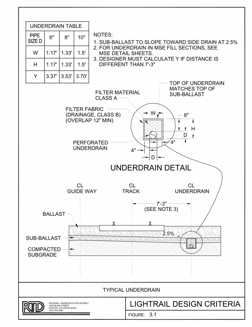
������������AB�
CDEF�
�D��
�D��
�F�
CD�C�
�DCC�
�DCC�
����
�D�E�
�D�E�
CDCE���
��
��
���������������B
�D��
���� �������������������
������ ��C!
��A"A�BB��
A�BB��
� #$������A�����
$� %�����������#������ $� %��A"A�BB��
%�B���%�A������������&��B����A!� '��B�$�����#��!
$��% ��������������
%�B���#�����B�B�����
� ��(
�D���A"A�BB��� ��B $�� �������������������D��
#�������B������DCD����������#�����B��B������%�������������%%���������E�"C�
�
E�"C�
�D�% ����������������#���%�BB����� ��&����
�
�
��
)�
)�
�
�B �B �B
%�����(
B������B������������������� ��B�����$ ��� ��������
�CFC!����"*FFF���'��&�� B ��� ��F�F�
��FF�AB��������
�$���B�����������
CD�
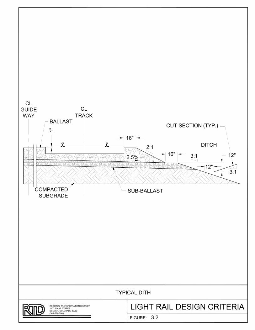
��
��
�����
��
ABCD
�EF����DC
��A���CD
�������
�A���������
���
���
����
CB���
���
�A���D��BE��������
���
���
� �
� �
!��
"BA�D�
�B�����B��CD�B����B�D�B��DBE����������E����BE��CB���B��
��#��� �$�%###CD�&D�'��E�E��CE�$#�#�
� ##�����D����DD�
���B����CB��
���

�������
���AB�C��BD�E��FB���A���C�����FC�BA�CFE���ACA��FBD�EA���A
�����B��������D�F����B�����CD�B�����
����B��C �BEA���A
���B��CD�F�BD�C��C!
�"�
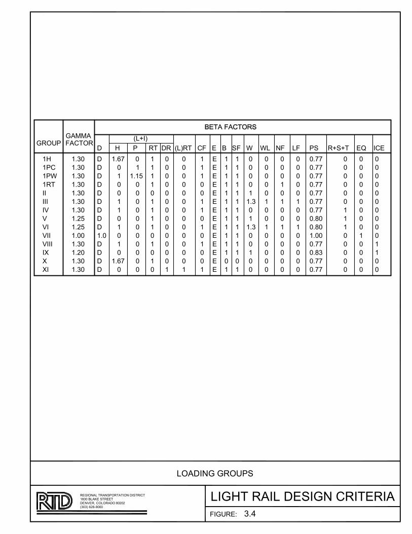
������������A��
BCDE
F�����������������������A��F�������A������������������������������������������������������A������������
�
B
�
�
B
B
�
B
�
B
�
�
BCDE
F
F
F
F
F
F
F
F
F
F
F
F
F
BC�
BCB�
B
�
�
�
�
�
�
�
�
�
�
�
�
B
B
B
B
�
B
B
B
B
�
B
�
B
� B
�
�
�
�
�
�
�
�
�
�
�
�
�
B
�
�
�
�
�
�
�
�
�
�
�
�
�
B
�
�
B
�
B
�
B
B
�
�
B
B
B �
�
�
�
�
�
�
�
�
�
�
�
�
�
B
B
B
B
B
B
B
B
B
B
B
B
�
B
B
B
B
B
B
B
B
B
B
B
B
B
�
B �
�
B
�
�
B
�
B
�
�
�
�
BC�
BC�
�
�
�
�
�
B
�
�
B
�
�
�
�
�
�
�
�
�
�
B
�
�
B
�
B
�
�
� �CEE
�CEE
�CEE
�CEE
�CEE
�CEE
�CEE
�C �
�C �
BC��
�CEE
�C �
�CEE
�CEE
BC��
BC��
BC��
BC��
BC��
BC��
BC��
BC!�
BC!�
BC��
BC��
BC!�
BC��
BC��
B�
B�
B��
B�A
��
���
�"
"
"�
�#
#
#�
"��
"���
�����
�
�
�
�
�
B
�
�
B
�
�
�
�
�
�
�
�
�
�
B
B
B
�
�
�
�
�
�
�
�
�
�
B
�
�
�
�
�
�
�
�
�
�
�
B
B
�
�
�
�
�
�
�
�
�
�
������$
����A������F��������A�������������A�������A�A����F��A��A
������D! %&���F��"��'������F�� �!�!
BD������(���A���A
���F����������
�C)
Regional Transportation District Section 4 - Trackwork Light Rail Design Criteria March 2013 Page 1 of 26
SECTION 4 – TRACKWORK 4.1 GENERAL .................................................................................................... 3
4.1.1 TRACK GAUGE .............................................................................. 3 4.2 GENERAL TRACK ALIGNMENT ....................................................................... 4
4.2.1 HORIZONTAL TRACK ALIGNMENT ................................................... 4 4.2.2 TANGENT SECTIONS ..................................................................... 4 4.2.3 CURVED SECTIONS ....................................................................... 5 4.2.4 CLEARANCES ............................................................................... 9
4.3 VERTICAL TRACK ALIGNMENT .................................................................... 12
4.3.1 GENERAL .................................................................................... 12 4.3.2 GRADES ..................................................................................... 12 4.3.3 VERTICAL CURVES ...................................................................... 13
4.4 MAINLINE TRACK ....................................................................................... 14
4.4.1 SUBGRADE ................................................................................. 15 4.4.2 SUBBALLAST .............................................................................. 15 4.4.3 GEOTEXTILE FABRICS .................................................................. 15 4.4.4 BALLAST .................................................................................... 16 4.4.5 CONCRETE CROSS TIES ............................................................... 16 4.4.6 TIMBER SWITCH TIES .................................................................. 16 4.4.7 RAIL .......................................................................................... 16 4.4.8 RESTRAINING RAILS .................................................................... 17 4.4.9 EMERGENCY GUARDRAILS ........................................................... 17 4.4.10 RAIL SEATS AND FASTENINGS ..................................................... 17 4.4.11 RAIL WELDS ............................................................................... 18 4.4.12 RAIL JOINTS ............................................................................... 18 4.4.13 RAIL/SWITCH HEATERS ............................................................... 19 4.4.14 SPECIAL TRACKWORK ................................................................. 19 4.4.15 PAVED TRACK ............................................................................ 20 4.4.16 DIRECT FIXATION TRACK (DF) ...................................................... 21 4.4.17 GRADE CROSSINGS ..................................................................... 22 4.4.18 MAINTENANCE ACCESS POINT ..................................................... 22 4.4.19 TRACK BUMPING POSTS .............................................................. 22 4.4.20 RAIL EXPANSION JOINTS ............................................................. 23 4.4.21 NOISE AND VIBRATION................................................................. 23
4.5 YARD TRACK ............................................................................................. 23
4.5.1 SUBBALLAST .............................................................................. 23 4.5.2 BALLAST .................................................................................... 23 4.5.3 CROSS TIES ................................................................................ 23 4.5.4 RAIL .......................................................................................... 23 4.5.5 RESTRAINING RAILS .................................................................... 24 4.5.6 GUARDRAILS .............................................................................. 24 4.5.7 RAIL JOINTS ............................................................................... 24
Regional Transportation District Section 4 - Trackwork Light Rail Design Criteria March 2013 Page 2 of 26
4.5.8 SPECIAL TRACKWORK ................................................................. 24 4.5.9 GRADE CROSSINGS ..................................................................... 24 4.5.10 CROSSWALKS ............................................................................ 24 4.5.11 YARD LIGHTING .......................................................................... 24 4.5.12 SERVICE ROADS ......................................................................... 25 4.5.13 CREW CHANGE PLATFORMS ........................................................ 25
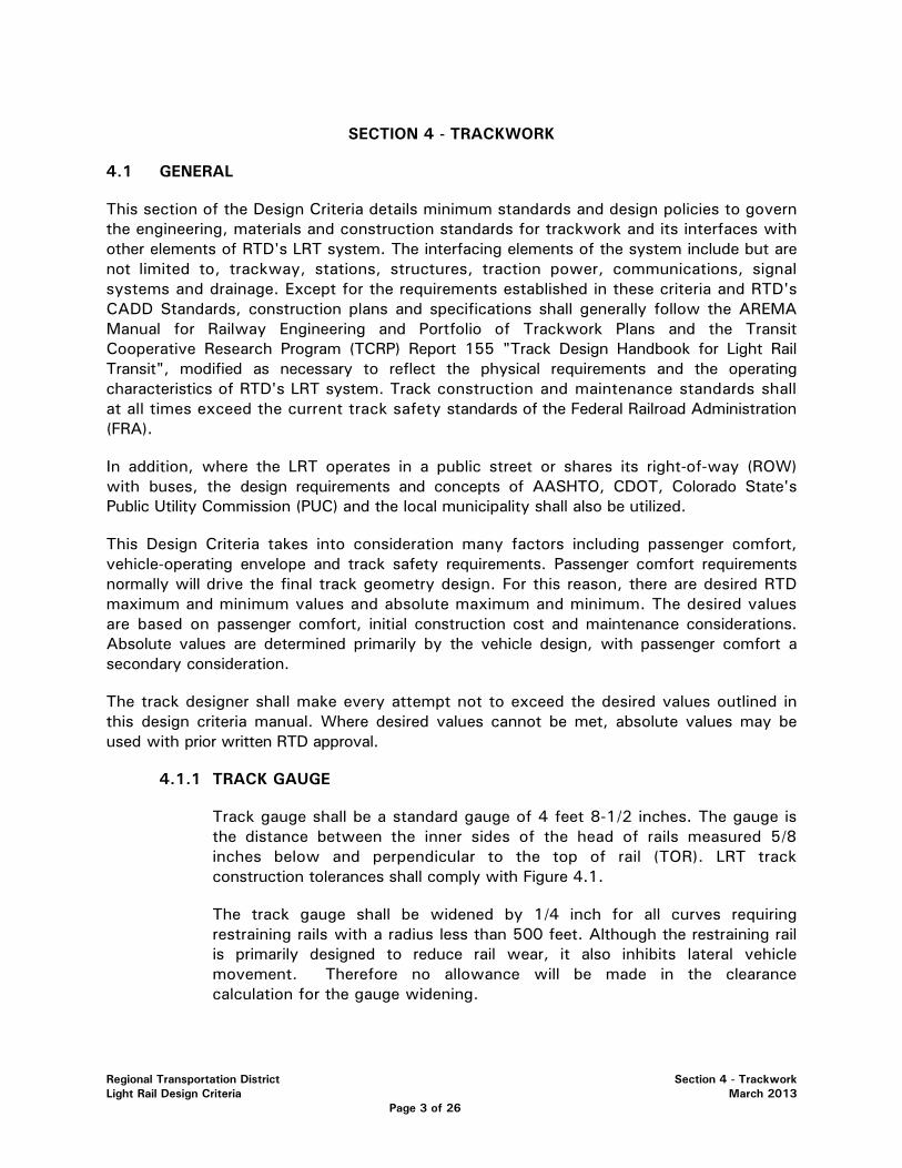
Regional Transportation District Section 4 - Trackwork Light Rail Design Criteria March 2013 Page 3 of 26
SECTION 4 - TRACKWORK
4.1 GENERAL
This section of the Design Criteria details minimum standards and design policies to govern the engineering, materials and construction standards for trackwork and its interfaces with other elements of RTD's LRT system. The interfacing elements of the system include but are not limited to, trackway, stations, structures, traction power, communications, signal systems and drainage. Except for the requirements established in these criteria and RTD's CADD Standards, construction plans and specifications shall generally follow the AREMA Manual for Railway Engineering and Portfolio of Trackwork Plans and the Transit Cooperative Research Program (TCRP) Report 155 "Track Design Handbook for Light Rail Transit", modified as necessary to reflect the physical requirements and the operating characteristics of RTD's LRT system. Track construction and maintenance standards shall at all times exceed the current track safety standards of the Federal Railroad Administration (FRA).
In addition, where the LRT operates in a public street or shares its right-of-way (ROW) with buses, the design requirements and concepts of AASHTO, CDOT, Colorado State's Public Utility Commission (PUC) and the local municipality shall also be utilized.
This Design Criteria takes into consideration many factors including passenger comfort, vehicle-operating envelope and track safety requirements. Passenger comfort requirements normally will drive the final track geometry design. For this reason, there are desired RTD maximum and minimum values and absolute maximum and minimum. The desired values are based on passenger comfort, initial construction cost and maintenance considerations. Absolute values are determined primarily by the vehicle design, with passenger comfort a secondary consideration.
The track designer shall make every attempt not to exceed the desired values outlined in this design criteria manual. Where desired values cannot be met, absolute values may be used with prior written RTD approval.
4.1.1 TRACK GAUGE
Track gauge shall be a standard gauge of 4 feet 8-1/2 inches. The gauge is the distance between the inner sides of the head of rails measured 5/8 inches below and perpendicular to the top of rail (TOR). LRT track construction tolerances shall comply with Figure 4.1.
The track gauge shall be widened by 1/4 inch for all curves requiring restraining rails with a radius less than 500 feet. Although the restraining rail is primarily designed to reduce rail wear, it also inhibits lateral vehicle movement. Therefore no allowance will be made in the clearance calculation for the gauge widening.

Regional Transportation District Section 4 - Trackwork Light Rail Design Criteria March 2013 Page 4 of 26
4.2 GENERAL TRACK ALIGNMENT
The track alignment shall be designed to maximize passenger ride quality at the highest permissible operating speeds. Where cost, geometric or other physical constraints permit, the Design Engineer shall establish alignment, superelevation and track clearance conditions which will permit 55 mph operation in the future by adjusting the actual superelevation.
The designer shall coordinate with Rail Operations and Service Planning as to the placement and location of crossovers and auxiliary tracks on the light rail system.
The LRT track alignment for each line section shall be stationed along the centerline of track North Bound "NB". Stationing along track "NB" shall be the basic control for locating all other system facilities along the route. Separate stationing shall be used for track "SB" where tracks are neither parallel nor concentric, where widened track centers are required around curves, or where tracks are in separate structures. The stationing along track "SB" shall be equated to track "NB" at the points where parallel alignment resumes. For East/West track, the East Bound (EB) will be the basic control.
4.2.1 HORIZONTAL TRACK ALIGNMENT
In general the horizontal alignment shall consist of tangent sections connected by circular curves with spiral transition curves unless otherwise approved by RTD.
4.2.2 TANGENT SECTIONS
The minimum length of tangent track between curved sections is based on passenger comfort and vehicle truck/wheel forces. Based on the AREMA Manual, Chapter 5, the minimum length is equal to the longest car that will traverse the system. Due to the forces between the trucks/wheels on the light rail vehicle (LRV) it is recommended that all trucks be on tangent track before negotiating a curve, at a minimum two sets of trucks should be on tangent track.
The minimum length of tangent between curved sections (except those with compound curves) shall be as follows:
TABLE 4A – TANGENT LENGTHS BETWEEN CURVED SECTIONS
Condition Tangent Length
Desirable Minimum 200 feet
*Minimum 100 feet or 3 times the design speed (in mph), whichever is larger
Absolute Minimum 50 feet
(* Not to be exceeded without prior written RTD approval)
(not applicable with compound curves)
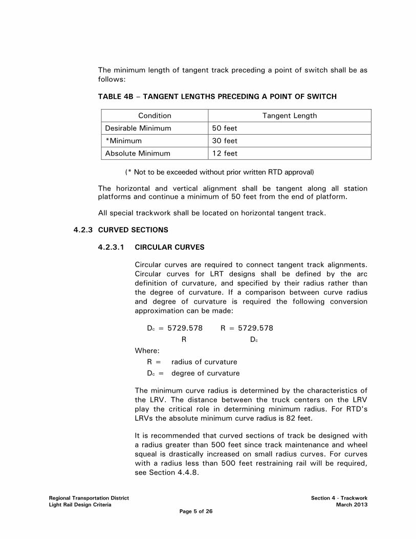
Regional Transportation District Section 4 - Trackwork Light Rail Design Criteria March 2013 Page 5 of 26
The minimum length of tangent track preceding a point of switch shall be as follows:
TABLE 4B – TANGENT LENGTHS PRECEDING A POINT OF SWITCH
Condition Tangent Length
Desirable Minimum 50 feet
*Minimum 30 feet
Absolute Minimum 12 feet
(* Not to be exceeded without prior written RTD approval)
The horizontal and vertical alignment shall be tangent along all station platforms and continue a minimum of 50 feet from the end of platform.
All special trackwork shall be located on horizontal tangent track.
4.2.3 CURVED SECTIONS
4.2.3.1 CIRCULAR CURVES
Circular curves are required to connect tangent track alignments. Circular curves for LRT designs shall be defined by the arc definition of curvature, and specified by their radius rather than the degree of curvature. If a comparison between curve radius and degree of curvature is required the following conversion approximation can be made:
Dc = 5729.578 R = 5729.578 R Dc
Where: R = radius of curvature Dc = degree of curvature
The minimum curve radius is determined by the characteristics of the LRV. The distance between the truck centers on the LRV play the critical role in determining minimum radius. For RTD's LRVs the absolute minimum curve radius is 82 feet.
It is recommended that curved sections of track be designed with a radius greater than 500 feet since track maintenance and wheel squeal is drastically increased on small radius curves. For curves with a radius less than 500 feet restraining rail will be required, see Section 4.4.8.

Regional Transportation District Section 4 - Trackwork Light Rail Design Criteria March 2013 Page 6 of 26
The minimum radius for a given curve is based on design speed, length of spiral and superelevation through the curve.
TABLE 4C – MINIMUM CURVE RADII
Condition Curve Radius
Desirable Minimum Structures 500 feet
Desirable Minimum Ballasted 300 feet
Absolute Minimum Ballasted 150 feet
Desirable Minimum Paved/DF 100 feet
Absolute Minimum Paved/DF 82 feet
The desired minimum length in feet of each curve element (spiral, simple curve, spiral) is 3 times the maximum speed in mph, or 100 feet whichever is longer.
Paved track is defined in section 4.4.15
For spiraled circular curves, the length in feet of the circular curve added to the sum of one half of the length of both spirals is an acceptable alternate method of determining minimum desirable curve lengths.
Double Spiraled Curves (curves that include no actual curve segment) will only be permitted in areas of extremely restricted geometry and no actual superelevation (Ea=0)
4.2.3.2 SPIRAL CURVES
Spiral curves shall be provided between circular curves with radii less than 10,000 feet and horizontal tangents. Spirals shall be Barnett or Talbot as defined by the AREMA Manual for Railway Engineering. See Figure 4.2 for spiral nomenclature.
Spirals are not permitted in or through at-grade crossings unless approved by RTD
The minimum length of spiral shall be the greatest length determined from the following formulas:
1. Ls = 1.63 EuV 2. Ls = 33 Ea 3. Ls = 60 feet

Regional Transportation District Section 4 - Trackwork Light Rail Design Criteria March 2013 Page 7 of 26
4. Ls = 30 feet in paved, embedded, and or DF sections only with NO Super elevation and speeds less than 10 MPH.
Where
Ls = Length of spiral curve (in feet) Ea = Track superelevation for the circular curve (in inches) Eu = Unbalanced superelevation for the circular curve
(in inches) V = Design Speed (in mph)
If the minimum spiral length obtained above is less than 1/100 of the curve radius, then spirals may be omitted with prior RTD approval.
4.2.3.3 SUPERELEVATION
Mainline tracks are designed with superelevations that permit desired design speeds to be achieved without resorting to excessively large curve radii. The design speed criteria stated below are based on a maximum lateral passenger acceleration of 0.1 g.
Et = Ea + Eu = 4V2 = 0.0007 V2 Dc R
Where: Et = Total superelevation required to balance the centrifugal
force at a given speed (in inches) Ea = Actual track superelevation to be constructed (in
inches) Eu = Unbalanced superelevation the difference between Et
and Ea (in inches). V = Design Speed (in mph) R = Radius of Curve (in feet) Dc = Degree of Curve
The amount of Eu shall vary gradually as follows:
Eu = 1.33 V² + 0.67 R Ea = 2Eu – 2
Actual track superelevation (Ea) shall not exceed 6 inches with a desired 4 inch maximum.
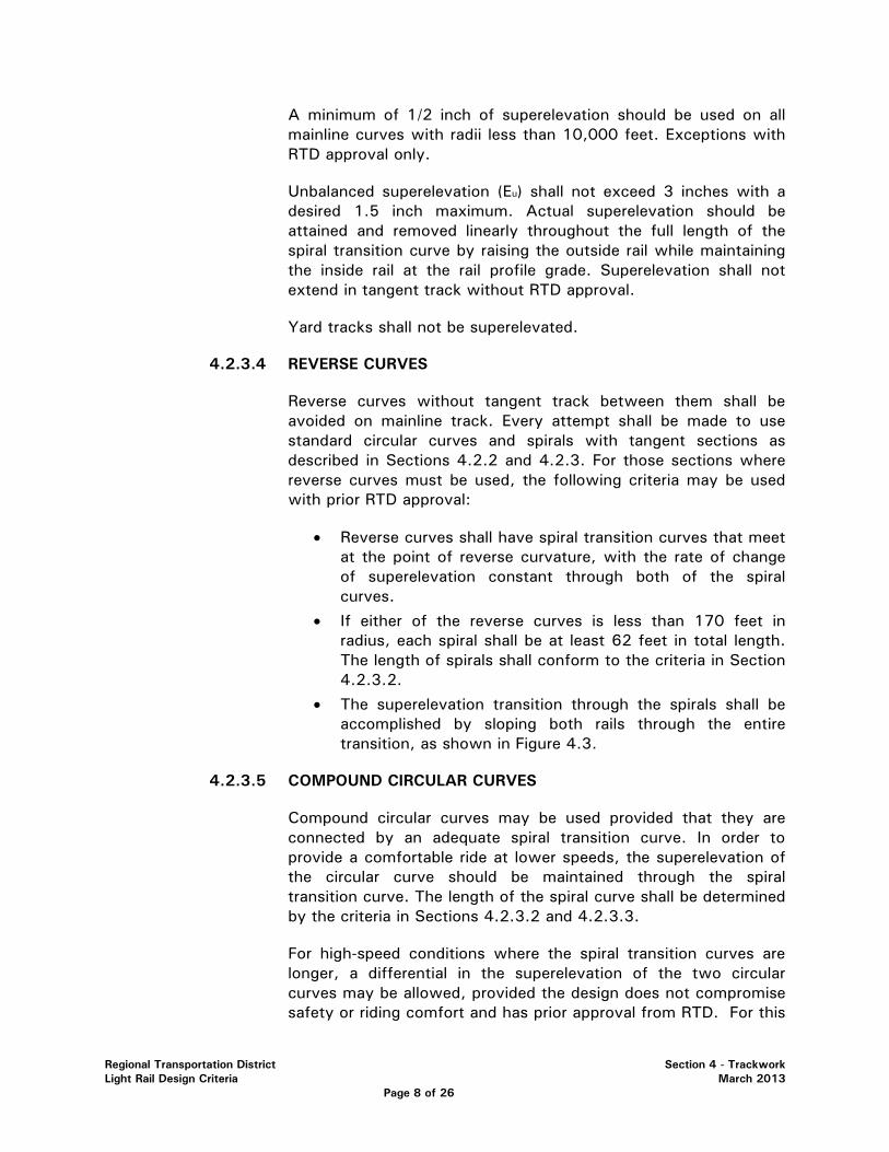
Regional Transportation District Section 4 - Trackwork Light Rail Design Criteria March 2013 Page 8 of 26
A minimum of 1/2 inch of superelevation should be used on all mainline curves with radii less than 10,000 feet. Exceptions with RTD approval only.
Unbalanced superelevation (Eu) shall not exceed 3 inches with a desired 1.5 inch maximum. Actual superelevation should be attained and removed linearly throughout the full length of the spiral transition curve by raising the outside rail while maintaining the inside rail at the rail profile grade. Superelevation shall not extend in tangent track without RTD approval.
Yard tracks shall not be superelevated.
4.2.3.4 REVERSE CURVES
Reverse curves without tangent track between them shall be avoided on mainline track. Every attempt shall be made to use standard circular curves and spirals with tangent sections as described in Sections 4.2.2 and 4.2.3. For those sections where reverse curves must be used, the following criteria may be used with prior RTD approval:
• Reverse curves shall have spiral transition curves that meet at the point of reverse curvature, with the rate of change of superelevation constant through both of the spiral curves.
• If either of the reverse curves is less than 170 feet in radius, each spiral shall be at least 62 feet in total length. The length of spirals shall conform to the criteria in Section 4.2.3.2.
• The superelevation transition through the spirals shall be accomplished by sloping both rails through the entire transition, as shown in Figure 4.3.
4.2.3.5 COMPOUND CIRCULAR CURVES
Compound circular curves may be used provided that they are connected by an adequate spiral transition curve. In order to provide a comfortable ride at lower speeds, the superelevation of the circular curve should be maintained through the spiral transition curve. The length of the spiral curve shall be determined by the criteria in Sections 4.2.3.2 and 4.2.3.3.
For high-speed conditions where the spiral transition curves are longer, a differential in the superelevation of the two circular curves may be allowed, provided the design does not compromise safety or riding comfort and has prior approval from RTD. For this
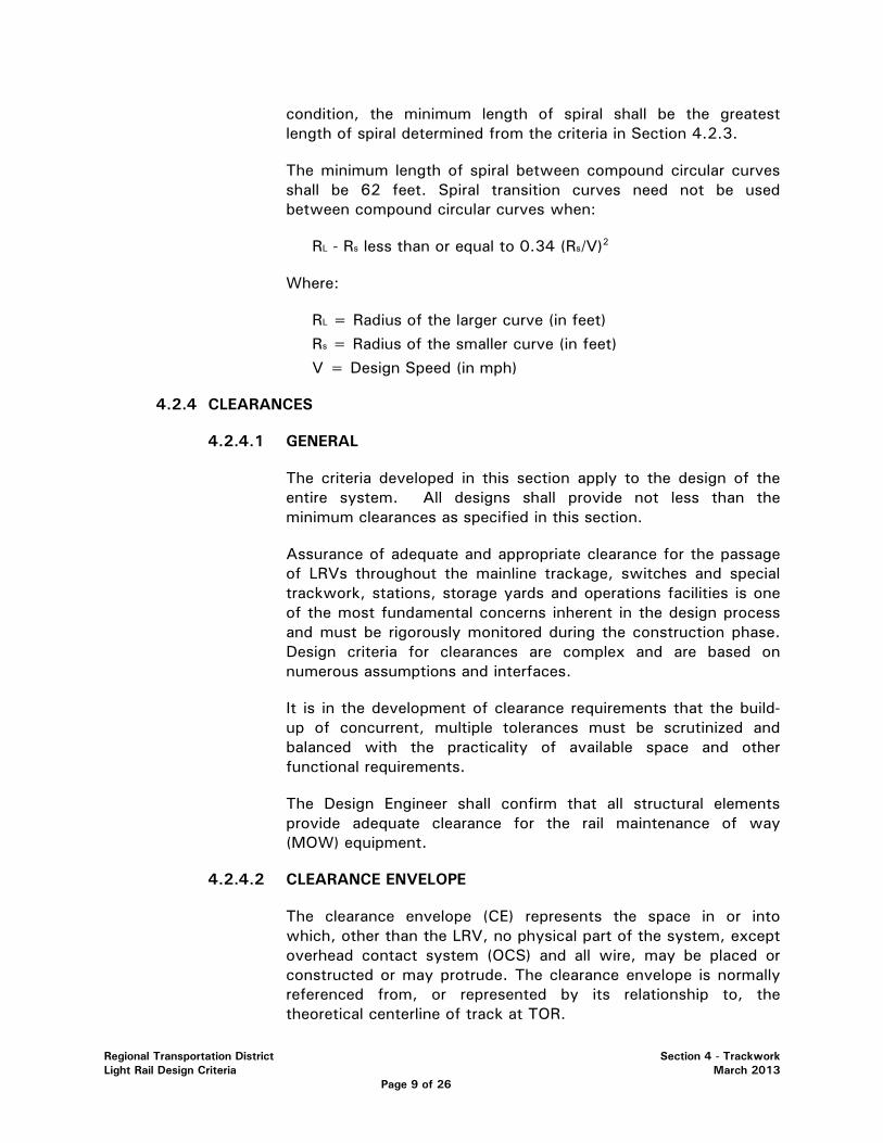
Regional Transportation District Section 4 - Trackwork Light Rail Design Criteria March 2013 Page 9 of 26
condition, the minimum length of spiral shall be the greatest length of spiral determined from the criteria in Section 4.2.3.
The minimum length of spiral between compound circular curves shall be 62 feet. Spiral transition curves need not be used between compound circular curves when:
RL - Rs less than or equal to 0.34 (Rs/V)2
Where:
RL = Radius of the larger curve (in feet) Rs = Radius of the smaller curve (in feet) V = Design Speed (in mph)
4.2.4 CLEARANCES
4.2.4.1 GENERAL
The criteria developed in this section apply to the design of the entire system. All designs shall provide not less than the minimum clearances as specified in this section.
Assurance of adequate and appropriate clearance for the passage of LRVs throughout the mainline trackage, switches and special trackwork, stations, storage yards and operations facilities is one of the most fundamental concerns inherent in the design process and must be rigorously monitored during the construction phase. Design criteria for clearances are complex and are based on numerous assumptions and interfaces.
It is in the development of clearance requirements that the build-up of concurrent, multiple tolerances must be scrutinized and balanced with the practicality of available space and other functional requirements.
The Design Engineer shall confirm that all structural elements provide adequate clearance for the rail maintenance of way (MOW) equipment.
4.2.4.2 CLEARANCE ENVELOPE
The clearance envelope (CE) represents the space in or into which, other than the LRV, no physical part of the system, except overhead contact system (OCS) and all wire, may be placed or constructed or may protrude. The clearance envelope is normally referenced from, or represented by its relationship to, the theoretical centerline of track at TOR.
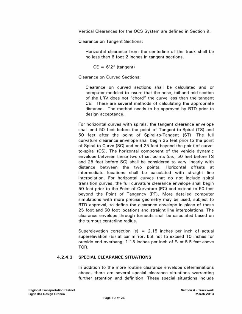
Regional Transportation District Section 4 - Trackwork Light Rail Design Criteria March 2013 Page 10 of 26
Vertical Clearances for the OCS System are defined in Section 9.
Clearance on Tangent Sections:
Horizontal clearance from the centerline of the track shall be no less than 6 foot 2 inches in tangent sections.
CE = 6’2” (tangent)
Clearance on Curved Sections:
Clearance on curved sections shall be calculated and or computer modeled to insure that the nose, tail and mid-section of the LRV does not “chord” the curve less than the tangent CE. There are several methods of calculating the appropriate distance. The method needs to be approved by RTD prior to design acceptance.
For horizontal curves with spirals, the tangent clearance envelope shall end 50 feet before the point of Tangent-to-Spiral (TS) and 50 feet after the point of Spiral-to-Tangent (ST). The full curvature clearance envelope shall begin 25 feet prior to the point of Spiral-to-Curve (SC) and end 25 feet beyond the point of curve-to-spiral (CS). The horizontal component of the vehicle dynamic envelope between these two offset points (i.e., 50 feet before TS and 25 feet before SC) shall be considered to vary linearly with distance between the two points. Horizontal offsets at intermediate locations shall be calculated with straight line interpolation. For horizontal curves that do not include spiral transition curves, the full curvature clearance envelope shall begin 50 feet prior to the Point of Curvature (PC) and extend to 50 feet beyond the Point of Tangency (PT). More detailed computer simulations with more precise geometry may be used, subject to RTD approval, to define the clearance envelope in place of these 25 foot and 50 foot locations and straight line interpolations. The clearance envelope through turnouts shall be calculated based on the turnout centerline radius.
Superelevation correction (e) = 2.15 inches per inch of actual superelevation (Ea) at car mirror, but not to exceed 10 inches for outside end overhang, 1.15 inches per inch of Ea at 5.5 feet above TOR.
4.2.4.3 SPECIAL CLEARANCE SITUATIONS
In addition to the more routine clearance envelope determinations above, there are several special clearance situations warranting further attention and definition. These special situations include
Regional Transportation District Section 4 - Trackwork Light Rail Design Criteria March 2013 Page 11 of 26
undercar clearances, vehicle interface at station platforms, and general walkway areas along the ROW where applicable.
A) UNDERCAR CLEARANCES
Vertical undercar clearance is defined from TOR with the maximum suspension deflection and car body roll, minimum vertical curve radius and fully worn wheels. The minimum vertical undercar clearance envelope shall be in accordance with Section 13.2.4.2.
B) STATION PLATFORM INTERFACE
The relationship of the vehicle at rest and the station platform is one of the most fundamental interfaces in any rail transit system. Horizontal and vertical static clearances or gaps (between platform edge and vehicle step) determine the ease of boarding/alighting for passengers, and platform edges often must be placed within the strict confines of clearance envelopes so as to permit safe and practical passenger movement.
Highblocks: The station platform interface shall include a platform edge located 65 inches horizontally from centerline of track and 35 inches vertically from TOR with a tolerance of +0.5 inches vertically and +/- 0.25 inches horizontally from track centerline on tangent track.
Curb Loading: The station platform interface shall include a platform edge located 55 inches horizontally from centerline of track and 6 inches vertically from TOR with a tolerance of +0.5 inches vertically and +/- 0.25 inches horizontally from track centerline on tangent track.
C) WALKWAYS ALONG STRUCTURES AND TUNNELS
An emergency/maintenance walkway shall be provided along structures and tunnels in accordance with Section 14.8. There shall be at least one walkway per track. Single track structures only need one walkway. This walkway shall be above Top of Tie and below TOR at the track edge and shall be located at a horizontal distance from track centerline as determined by regulations. The walkway shall have a minimum width of 30 inches.
D) WALKWAY AREA ALONG TRACKWAY
In addition to the clearance envelope requirements per Section 4.2.4.2, it is desirable that space be provided for maintenance walkways adjacent to the trackway. The walkway envelope shall

Regional Transportation District Section 4 - Trackwork Light Rail Design Criteria March 2013 Page 12 of 26
extend at least 2 feet-6 inches from the edge of the clearance envelope and shall extend to 6 feet-6 inches above the walkway. Unless otherwise approved by RTD, walkways shall be provided on both sides of the ROW, and shall permit unobstructed passage from which passengers can be evacuated. For walkway clearance calculations only, traction power poles shall not be considered a permanent obstruction. If there are two parallel grade separated single track structures, the requirement is to have a minimum 30 inch walkway on each structure.
This requirement is not applicable to paved track sections in street ROW.
E) TRACK CENTERS WITH CENTER POLES
For open track with center traction power poles, the track centers shall be calculated based on the appropriate clearance envelopes, a design width for the traction power poles of 14 inches, and lateral deflection due to loading of 0.75 inches below 15 feet from TOR and 1.0 inch above 12 feet from TOR.
Figure 4-6 provides a simplified outline of the clearance envelope of the LRV.
4.3 VERTICAL TRACK ALIGNMENT
4.3.1 GENERAL
Vertical alignment shall be defined by the "top-of-rail profile" along tangent sections and the low rail in superelevated sections. Parabolic vertical curves having a constant rate of change in grade shall be employed for changes in gradient.
4.3.2 GRADES
Grades shall not exceed the maximums specified below:
TABLE 4D – MAXIMUM VERTICAL GRADES
Condition *Desirable Maximum Absolute Maximum
Mainline Track 3.5% 6.0% (not more than 2500
ft.)
Stations 1.0% 2.%
Yard 0.0% 0.5%
Storage Track 0.0% 0.25%

Regional Transportation District Section 4 - Trackwork Light Rail Design Criteria March 2013 Page 13 of 26
Special Trackwork 0.0% 4.5%
(* Not to be exceeded without prior written RTD approval)
All tracks entering the yard shall be pitched downward away from the main line, or dished to prevent any vehicles from rolling onto the mainline tracks.
Grade shall be equalized to the most practical extent possible.
The minimum length of constant profile grade between vertical curves shall be determined as follows:
Lg = 3V
Where:
Lg = Minimum length of constant profile grade (feet) V = Design velocity through tangent (miles per hour)
Absolute minimum Lg shall be 90 feet, unless otherwise approved by RTD.
4.3.3 VERTICAL CURVES
4.3.3.1 LENGTH OF VERTICAL CURVES
The minimum length of vertical curve shall be determined as follows:
L = 70(G1-G2) for V greater than or equal to 35 L = 40(G1-G2) for 15 less than or equal to V< 35 L = 20(G1-G2) for V< 15
Where:
L = Length of vertical curve (in feet) (G1-G2) = Algebraic difference in grades (%) V = Design Velocity (in mph)
Standard Vertical Curves are shown in Figure 4.7.
The minimum length of any vertical curve shall be as follows:
TABLE 4E – VERTICAL CURVES – MINIMUM LENGTH
Condition Length of Vertical Curve
*Desirable Minimum 200 feet

Regional Transportation District Section 4 - Trackwork Light Rail Design Criteria March 2013 Page 14 of 26
Absolute Minimum 150 feet
(* Not to be exceeded without prior written RTD approval)
Vertical curves shall not exceed the limits identified in Section 4.3.3.4.
Vertical curves are not allowed in at-grade crossings. Vertical curves shall be at least 70 ft. away from the nearest at-grade crossing panel or pavement.
4.3.3.2 REVERSE VERTICAL CURVES
Reverse vertical curves may be used provided the minimum length of each curve is not less than that defined by Section 4.3.3.1, and prior RTD approval has been obtained.
4.3.3.3 COMPOUND VERTICAL CURVES
Compound or non-symmetrical vertical curves may be used provided the requirements of Section 4.3.3.1 are met, and prior RTD written approval has been obtained.
4.3.3.4 COMBINED VERTICAL AND HORIZONTAL CURVES
A four-car train shall be capable of negotiating a combined (horizontal and vertical) curved section involving:
• 82 foot radius horizontal curve and 1640 foot vertical radius either crest or sag.
• 89 foot radius horizontal curve and an 1150 foot vertical radius sag curve.
• 95 foot radius horizontal curve and an 820 foot vertical radius crest.
To equate Vertical Radius to Vertical Curve Length: Rv = (Lvc)/0.01*(G1-G2) Where: Rv = Vertical radius Lvc = Length of vertical curve G1-G2 = Algebraic difference in grades (%)
Combined horizontal and vertical curves shall not be more restrictive than these absolute minimum requirements.
4.4 MAINLINE TRACK
For typical track sections, refer to Figures 4.8, 4.9, and 4.10. For Retained Sections see
Regional Transportation District Section 4 - Trackwork Light Rail Design Criteria March 2013 Page 15 of 26
Structural Figures 6.2, 6.3, and 6.4.
4.4.1 SUBGRADE
The subgrade 11 feet both sides of track centerline shall be compacted to a minimum density of 95% of the maximum density determined in accordance with AASHTO T 180. The subgrade shall be in a moist condition (within ±2% of the optimum moisture content as determined by AASHTO T 180.
If laboratory results indicate that existing material is unsuitable, the material must be removed and replaced with clean, sound and properly compacted material, per ASTM standards.
The compacted subgrade shall be sloped at 40:1 downward and away from the center point located midway between the two tracks in double track territory. In single track areas, the compacted subgrade shall slope toward the underdrain at 40:1. Refer to Figures 4.8, 4.9 and 4.10 for typical subgrade configurations.
Configurations other than those mentioned above may be adopted if drainage requirements or specific locations dictate a special treatment with prior RTD approval.
4.4.2 SUBBALLAST
Subballast is the transition zone between the subgrade and the ballast. The subballast acts as a barrier filter separating the ballast section from the subgrade material. This material plays an integral role in the track structure. The quality of the subballast has a direct relationship to the overall performance of the track structure. This layer acts as a drainage median for the track bed.
An 8 inch layer of subballast shall be installed on top of the subgrade. The subballast shall conform to AREMA specifications. Subballast should extend the full width of the subgrade and at a minimum 24 inches past the toe of the ballast.
A minimum of 5 inches of Hot Mix Asphalt (HMA) may be used in place of subballast and Geotextile. The mix shall be engineered for railway use and must be approved by RTD.
4.4.3 GEOTEXTILE FABRICS
Geotextile fabrics shall be placed under all special trackwork on the mainline and in the yard, and tracks with potential subgrade stability issues where directed by Geotechnical Engineer. Fabric will extend the entire interface zone between the ballast and subballast. Fabric will extend 20 feet before point of switch and 10 feet after the last long tie. Geotextile fabric specifications shall be as recommended by a Geotechnical Engineer.

Regional Transportation District Section 4 - Trackwork Light Rail Design Criteria March 2013 Page 16 of 26
4.4.4 BALLAST
No. 4 (1-1/2 inches to 3/4 inches) and or No. 3 (2 inches to 1 inch) ballast conforming to AREMA specifications shall be used on all main tracks except for those in streets and yards, where No. 5 (1 inch to 3/8 inch) ballast will be used. All ballast is to be thoroughly washed and or re-screened (0.5% maximum passing #200 sieve) as necessary to remove fine particles prior to placement.
A minimum depth of 8 inches of ballast shall be used between the bottom of ties and top of the subballast. The ballast shoulder shall extend 16 inches beyond the ends of the ties parallel to the plane formed by the top of the rails. Ballast shoulder shall then slope downward to the subballast at a 2:1 slope. The final top of ballast elevation shall be one inch below the top of tie, when compacted. Refer to Figures 4.8, 4.9 and 4.10.
Ballast shall be placed in-between track, around platforms and other areas where the tracks are splayed out.
4.4.5 CONCRETE CROSS TIES
Mainline tracks shall use concrete cross ties, approximately 8 feet 3 inches in length and 7 inches by 9 inches in cross section spaced 30 inches, center to center. Tie spacing through curves with less than 1000 feet radii shall be 27 inches. All concrete cross ties shall conform to AREMA specifications.
4.4.6 TIMBER SWITCH TIES
Timber switch ties shall be of various lengths conforming to the specific requirements of the turnouts used. Anti-splitting devices shall be used on all wood ties. Ties shall be free of twist, bow and detrimental splitting.
4.4.7 RAIL
Rail for all mainline track shall be 115 RE section, new Premium or Standard rail manufactured in accordance with current AREMA specifications (See Figure 4.11). Used No. 1 or new IQ rails may be used in yard and other non-main tracks.
High Carbon (0.90% Carbon minimum) rails shall be used in all special trackwork and on all curves of radii equal to or less than 600 feet and extending into the spiral until the point of radius on spiral exceeds 600 feet. High Carbon rails shall not be installed on seldom used emergency or storage tracks, even though they may satisfy the above criteria. High Carbon rails may be used in other locations where excessive rail wear is anticipated.
All rails shall be ground to remove mill scale from the top and gauge side profile of the rail head prior to the start of integrated/acceptance testing.
Regional Transportation District Section 4 - Trackwork Light Rail Design Criteria March 2013 Page 17 of 26
Rail in curves of radii equal to or less than 300 feet shall be precurved using standard shop practices.
4.4.8 RESTRAINING RAILS
Restraining rails are used to provide continuous support to LRVs negotiating sharp radius curves. This use of restraining rails reduces the wear to the flanges and to the rail also reducing the possibilities of a derailment.
All mainline track excluding special trackwork with a centerline radius of 500 feet or less shall have inner restraining rail mounted adjacent to the low rail in accordance with RTD plans and specifications. The flangeway shall be set at 2 inches wide to engage the back of the inside wheel. Restraining rail shall extend beyond the curve on both ends a minimum distance of 10 feet. Restraining rail shall be continuously welded (CWR) or jointed to prevent rail end offset. Restraining rail detail is shown on Figure 4.12.
Restraining rail joints shall be bolted using D-bar installation.
4.4.9 EMERGENCY GUARDRAILS
Emergency guardrails are used as a safety device. In the event of a derailment, the guardrail is designed to catch the inside of the wheel and guide the LRT along the track until it stops and/or to prevent derailed LRV from striking an abutment wall or any support structure. Emergency guardrails shall be installed adjacent to the inside running rail of all tracks on bridges and fills with a vertical drop (slope greater than 0.5:1) of more than 5 feet at a distance within 15 horizontal feet of track centerline. Guardrails shall also be applied where the guideway is located adjacent to major structures, unless that structure is constructed with an approved safety barrier. Emergency guardrails will not be installed within the limits of special trackwork or restraining rail. Guardrail is required under overhead bridges unless the overhead structure has sufficient crash wall protection.
Emergency guardrail shall be designed so as to retain the wheels of a derailed vehicle moving at maximum speed. The striking face of the emergency rail shall be uniformly located approximately 1 foot from the gauge line of the running rail. Guardrail shall be fastened to every second tie in ballasted track.
4.4.10 RAIL SEATS AND FASTENINGS
Due to the negative return requirements, the rail seats and fasteners not only hold the rail to the ties; they also need to insulate the rail from the ground (see Figure 4.13). Concrete and wooden cross ties will use spring clips isolated from the tie using plastic insulators and placed on an insulating pad. Rail anchors will not be needed or used.
Regional Transportation District Section 4 - Trackwork Light Rail Design Criteria March 2013 Page 18 of 26
Other rail fastening methods shall be evaluated for street track, ballasted track and Special Trackwork. Direct fixation rail fasteners shall provide the required lateral and longitudinal restraint for continuous welded rail (CWR) and the electrical insulation required for the negative return current and the proper operation of different frequency phase selective track signal circuits. Direct fixation fasteners or concrete ties shall provide a 40:1 cant of the rail.
Direct fixation fasteners shall incorporate, or be placed on, a suitable elastomeric pad for reducing transmission of high frequency (i.e., greater than 30 Hz) loads to the support structure.
Rail fasteners for use in direct fixation special trackwork shall be of a design compatible with the standard fastener used in conventional direct fixation track.
Rail clips or other devices used in direct fixation fasteners shall produce the required longitudinal rail restraint after repeated load testing in accordance with AREMA Chapter 10, except load application angle in that test shall be 27˚. The clearance envelope for direct fixation fasteners is shown in Figure 4.15.
Design and analysis of direct fixation fasteners on aerial structures requires careful coordination between the track and structural engineer specifically with respect to Rail/Structure Interaction loads and forces. Reduced fastener spacing may be required on bridges and approaches with sharp curves. Refer to chapter 6.
4.4.11 RAIL WELDS
Rail shall be welded into CWR strings of site-specific length by the electric flash-butt or aluminothermic weld processes in accordance with AREMA specifications. The ends of the welded rail strings will then be field-welded together by the thermite welding or flash-butt process according to AREMA specifications. All welds will be ultrasonically proof tested with documentation delivered to RTD prior to service operation. Thermite welds shall not be located in, or within, 25 ft. of pavement edge of an at grade crossing.
Contractor shall provide a CWR Rail Laying Plan prior to rail construction that complies with “Procedures for the Installation, Adjustment, Maintenance, and Inspection of CWR as Required by 49 CFR 213.119”
4.4.12 RAIL JOINTS
Insulated and standard rail joints shall be placed only at locations where required to accommodate signal track circuits and connections to special trackwork. The insulated rail joints for signal operations shall be prefabricated plugs, welded into the CWR rail using the welding techniques specified in 4.4.11. Insulated plugs should be trimmed down to 14 feet. Only frogs may
Regional Transportation District Section 4 - Trackwork Light Rail Design Criteria March 2013 Page 19 of 26
be bolted. Insulated joints shall use huckbolts. Restraining Rail Insulated joints may be bolted. If rail is temporarily jointed, drill pattern shall be such that end hole is not drilled (two holes per rail end), so that future joint welding may be accommodated. Any other bolted connection must be approved by RTD. In no case will joints be located within street or pedestrian crossings.
4.4.13 RAIL/SWITCH HEATERS
Electric switch heaters shall be installed on all power and spring operated turnouts in both mainline and yard tracks in accordance with requirements of the signal system. A list of approved manufacturers and types can be obtained from RTD. Others may be submitted for approval.
4.4.14 SPECIAL TRACKWORK
Special trackwork shall be manufactured and installed in accordance with RTD's specifications generally following AREMA plans and specifications. All frogs and flangeways shall be designed to accommodate the LRV wheel profile.
All special trackwork shall be fabricated using galvanized lag screws and Pandrol e-clips. (no spikes)
The preferred location of special trackwork is in ballasted at-grade areas. Single crossovers shall be used in lieu of double crossovers unless space restrictions dictate their use, and then only with prior approval by RTD. Special trackwork in paved track shall be kept to an absolute minimum; however, when it must be so located, it shall be designed to reduce the exposure of pedestrians to the operating mechanisms. Switch points shall not be located in areas designated as pedestrian crossings. Special trackwork shall be located at least 50 ft. from the edge of Station Platforms.
All special trackwork shall be located on vertical and horizontal tangents. The desirable minimum horizontal and vertical tangent distance preceding a point of switch shall be 50 feet (absolute minimum shall be 20 feet with prior RTD written approval). Special trackwork shall not be super elevated.
Special trackwork should be located off and 250 feet beyond the end of direct fixation bridges where ever possible. Special trackwork shall not be partially supported by direct fixation. When special trackwork is located on a direct fixation bridge, special girders and anchors may be required. The layout of the special trackwork shall be coordinated to minimize relative movement between rails and the superstructure at switch locations.
As special trackwork is a source of noise and vibration, its location shall be selected to minimize their effect.
Regional Transportation District Section 4 - Trackwork Light Rail Design Criteria March 2013 Page 20 of 26
Operating speed through turnouts shall be as indicated in Figure 4.16. Turnouts and crossovers for various applications shall be selected in accordance with the following criteria:
• As a minimum, No. 8 turnouts (19 feet-6 inch curved switch points) shall be used on mainline ballasted track, although No 10 turnouts are preferred where feasible and topography allows. At specific locations where high-speed operation is essential No. 20 turnouts (39 feet-0 inches switch points) are preferred. Switches on #20 or larger turnouts shall be equipped with circuit controllers and helper rods.
• No. 8 turnouts (19 feet-6 inch curved switch points) shall be the standard mainline turnout in paved track areas.
• No. 6 turnouts (13 feet-0 inch curved switch points) shall be used on the mainline in areas where space limitations prevent the use of No. 8's with prior RTD approval.
• The use of Slip switches and Double Slip switches shall be avoided.
• Diamonds shall only be permitted where both intersecting tracks are tangent both horizontally and vertically.
Rail clips shall be installed in lieu of cut spikes on ties for special trackwork.
All turnouts shall use AREMA Point Detail 5100 with graduated risers. All mainline track frogs shall be of the rail-bound manganese type with high Carbon steel guardrails. Self-guarded frogs are to be used in yard tracks. Paved track switch points shall be bolted to closure rails with a solid heel block.
Special drainage provisions shall be made in paved track turnouts to preclude standing water in flangeways, switch points and in switch-throwing mechanisms.
Special trackwork in paved areas shall have removable replaceable precast concrete panels throughout the special trackwork limits.
4.4.15 PAVED TRACK
All road and street design shall be in accordance with the current specifications and design guidelines of the involved local jurisdictions. For those cases where the local jurisdictions have no design guidelines, the Colorado Department of Transportation (CDOT) Design Standards shall be used.
Corrosion preventive measures must be utilized on all embedded track components.
Trackwork located in streets shall use 115RE rail on concrete ties, except for special trackwork, which will use timber switch ties on AREMA No. 5
Regional Transportation District Section 4 - Trackwork Light Rail Design Criteria March 2013 Page 21 of 26
ballast. Figure 4.17 shows paved track with a concrete surface. Figure 4.18 shows typical section of rail connection detail in embedded track. Flangeway filler material shall have a volume resistivity of 1012 ohm-cm or greater. Flangeway filler shall be a “Polypro EPFLEX RAILSEAL field side spec 12-621 and gauge side 12-622” or approved equal. The flangeway filler shall be formed to tightly surround the e-clips and or other specified railroad tie fasteners. Fasteners under the flangeway filler shall be galvanized and be coated with a corrosion resistant material.
Particular attention shall be directed toward proper drainage of street trackage. The adjacent surface pavement shall be designed so surface water will drain away from the track. Track drains shall be used to prevent water from standing. In areas of special trackwork, particular attention will be directed to provide drainage for the special trackwork units and switch-throwing mechanisms. When possible, track drains shall be located in tangent track.
The pavement material shall match the top of the flangeway filler on the field side to prevent the wheel tread from damaging the pavement material. An elastic or filler material shall be placed between the rails and pavement materials in order to prevent damage to the pavement materials and increase electrical isolation. Filler material shall be flush with the top of rail. Any application of flangeway filler shall allow for the future removal of the rail. Rail clips in paved track shall be protected from corrosion.
Pre Cast panels, when used in place of paving, shall be installed with the top of panel surface flush with the top of rail elevation. Rail head shall not be above panel height.
4.4.16 DIRECT FIXATION TRACK (DF)
Direct fixation (DF) track is a ballastless track structure in which the rail is mounted on direct fixation fasteners that are attached to a concrete deck or slab. Trackwork located on DF shall use 115RE rail attached to the direct fixation fasteners using spring clips and isolated from the structure using elastomeric pad and plastic insulators.
Grade separated structures 400 feet or longer in length, including bridge, tunnels and cut and cover structures will require DF unless analysis indicates otherwise and approval by RTD is grated. It shall consist of a second pour concrete plinth block and a fastening system to hold the running rails onto the concrete surface canted 1:40 toward the track centerline. An approach slab shall be provided at each transition between DF and ballasted track.
DF sections shall be designed for storm water runoff of a 100-year storm event.
Regional Transportation District Section 4 - Trackwork Light Rail Design Criteria March 2013 Page 22 of 26
4.4.17 GRADE CROSSINGS
Mainline grade crossings shall be prefabricated and made of durable, long-lasting materials. Grade crossing panels shall be constructed with due regard to removability for track maintenance, electrical isolation, to non-interference with electrical track circuits or rail fastenings, tire adhesion and slip resistance for vehicles and pedestrians. End panels shall be equipped with slope ramps, from top edge of panel to surface of ballast, to protect equipment hanging from vehicle.
Grade crossings shall be located on tangent track and away from special trackwork areas unless otherwise approved by RTD. Rail joints and thermite welds shall not be located in grade crossings.
Panel top elevation shall be flush with top of rail elevation for the entire length of crossing. Rail head shall not be above panel height.
Parallel tracks shall be coplanar though at-grade crossing.
Cross tie size and spacing at grade crossings shall be in accordance with the grade crossing manufacturer's recommendations.
Crosswalks shall be provided at areas where pedestrians will be crossing mainline tracks. They shall be located on tangent track, if possible, and away from special trackwork areas.
Horizontal curves and spirals shall not be located in at grade crossings
Vertical curves shall not be located in at grade crossings
4.4.18 MAINTENANCE ACCESS POINT
Access points for maintenance personnel and equipment shall be provided everywhere possible. Areas shall be provided at or near wayside equipment for the parking of maintenance vehicles to prevent infringing on highway travel lanes or pedestrian areas. Tail track shall be constructed with adjacent paved walkway(s), 30 inches wide and 4 inches thick.
High-rail access points shall be provided at least every 2 miles. They shall be located on tangent track and be constructed of grade crossing materials durable enough to withstand maintenance vehicles. High-rail access points shall be adequately secured to prevent unauthorized entry.
4.4.19 TRACK BUMPING POSTS
Track bumping posts shall be designed to clear the coupler and engage the car’s anti-climber. They shall be installed at the ends of all stub-end yard and mainline tracks. Track bumping post shall be primed and painted yellow.

Regional Transportation District Section 4 - Trackwork Light Rail Design Criteria March 2013 Page 23 of 26
4.4.20 RAIL EXPANSION JOINTS
During final design, locations where rail expansion/contraction is anticipated to present a problem (on bridges and certain sharp curves on ballasted track), shall be analyzed for methods of control. If mechanical rail expansion joints are used, the expansion capacity of the joints shall be greater than the anticipated rail movement within the full range of rail temperatures. Expansion joints must be bonded for negative return electrical conductivity.
4.4.21 NOISE AND VIBRATION
Noise and vibration shall be measured and mitigated, if necessary, according to environmental studies and the current FTA guidelines.
4.5 YARD TRACK
Yard tracks will be constructed to the same standards as mainline track, with the following exceptions:
4.5.1 SUBBALLAST
Subballast will not be required unless it is needed for subgrade stabilization. Use of subballast shall be as recommended by a Geotechnical Engineer.
4.5.2 BALLAST
No. 5 ballast conforming to AREMA specifications shall be used on at least the top 2 inches on all yard tracks. No. 4 ballast may be used for the remainder of the section.
A minimum depth of 9 inches of ballast shall be used between the bottom of tie and top of subgrade. The top of ballast elevation shall be at least 1 inch below the base of rail yet fills the tie crib to 1 inch from top of tie. The ballasted shoulder shall extend level 18 inches level on the field side with a maximum slope of 2 foot horizontal to 1 foot vertical beyond the 18 inches. Crushed slag ballast will not be permitted.
4.5.3 CROSS TIES
Yard tracks shall use timber cross ties 9 feet in length spaced 26 inches center to center, except at braced and guarded track, where spacing shall be 24 inches. All cross ties shall be size 7 inches by 9 inches and conform to AREMA specifications. Switch ties shall be of various lengths as required for a No. 6 AREMA turnout with 13 feet-0 inch switch points.
4.5.4 RAIL
Yard tracks shall be constructed with 115 pound CWR new Standard or IQ (Industrial Quality). Used No. 1 rail may be used with prior RTD approval.
Regional Transportation District Section 4 - Trackwork Light Rail Design Criteria March 2013 Page 24 of 26
4.5.5 RESTRAINING RAILS
All yard track curves, with a centerline radius of 300 feet or less, shall have restraining rails mounted adjacent to the inside rail in accordance with AREMA plans and specifications.
4.5.6 GUARDRAILS
Emergency guardrails shall be installed on tracks adjacent to all major structures that may cause extensive damage to a car in the event of a derailment or intrusion into the mainline envelope.
4.5.7 RAIL JOINTS
Rail joints shall not be used.
4.5.8 SPECIAL TRACKWORK
Special trackwork shall conform to the requirements of Section 4.4.14.
All yard turnouts shall be AREMA No. 6's with 13 feet-0 inch curve switch points conforming to AREMA Point detail 5100 with graduated risers. Self-guarded frogs shall be used.
The switch stand area shall have a level and sufficient area for switch tending.
The operating speed through the turnouts shall be as indicated in Figure 4.16.
4.5.9 GRADE CROSSINGS
Grade crossings shall conform to the requirements of Section 4.4.17, except yard grade crossings may consist of asphalt with flangeway liners.
4.5.10 CROSSWALKS
Crosswalks shall conform to the requirements of Section 4.4.17. In the yard, they may be located on curves and may consist of asphalt.
4.5.11 YARD LIGHTING
The yard is to be illuminated to provide a safe working environment for ultimate 24-hour operation of the facility. Yard lighting will also provide an element of security. Yard lighting shall be in conformance with local requirements.

Regional Transportation District Section 4 - Trackwork Light Rail Design Criteria March 2013 Page 25 of 26
4.5.12 SERVICE ROADS
Service roads shall be provided around the operations facility and between alternate pairs of tracks in the LRV storage areas. Service roads shall also be provided to access switches within the yard. Service roads shall be designed as applicable to the need.
4.5.13 CREW CHANGE PLATFORMS
Paved crew change platforms with gates shall be provided.
Regional Transportation District Section 4 - Trackwork Light Rail Design Criteria March 2013 Page 26 of 26
LIST OF FIGURES
FIGURE 4.1 ....... TRACK CONSTRUCTION TOLERANCES FIGURE 4.2 ...... CURVE & SPIRAL NOMENCLATURE FIGURE 4.3 ....... SUPERELEVATION TRANSITIONS FOR REVERSE CURVES FIGURE 4.4 ....... INTENTIONALLY LEFT BLANK FIGURE 4.5 ....... INTENTIONALLY LEFT BLANK FIGURE 4.6 ....... LRV DYNAMIC ENVELOPE FIGURE 4.7 ....... STANDARD VERTICAL CURVES FIGURE 4.8 ....... SINGLE TRACK BALLASTED TRACK SECTION FIGURE 4.9 ....... DOUBLE TRACK BALLASTED TRACK SECTION FIGURE 4.10 ..... INTENTIONALLY LEFT BLANK FIGURE 4.11 ..... 115RE RAIL SECTION FIGURE 4.12 ..... RESTRAINING RAIL DETAIL FIGURE 4.13 ..... STANDARD STEEL TIE PLATE ASSEMBLY FIGURE 4.14 ..... STANDARD STEEL TIE PLATE FOR LAG SCREW INSTALLATION FIGURE 4.15 ..... CLEARANCE ENVELOPE FOR DIRECT FIXATION TRACK FIGURE 4.16 ..... TURNOUT OPERATING SPEEDS FIGURE 4.17 ..... PAVED TRACK FIGURE 4.18 ..... EMBEDDED RAIL DETAIL
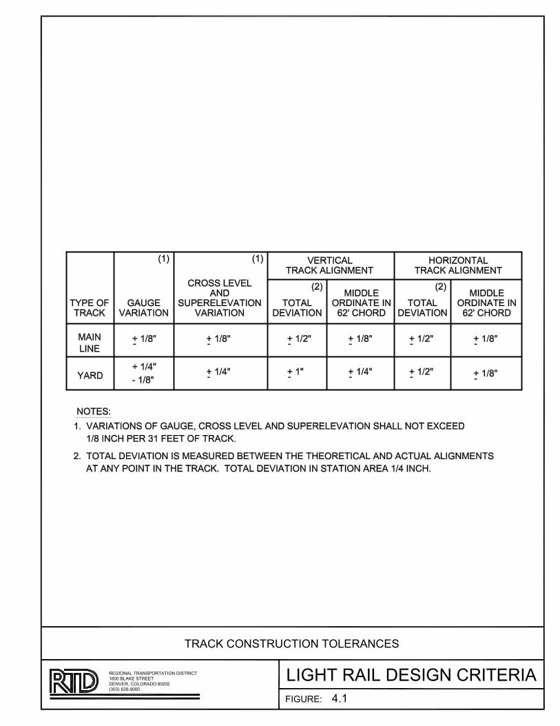
�������
���AB�C��BD�E��FB���A���C�����FC�BA�CFE���ACA��FBD�EA���A
�����B��������D�F����B�����CD�B�����
����B��C �BEA���A
A�C� B��FEA���A��FBA����CF��E
!"�

�
��
�
���
���
�����
AB�CD
��
��
�
E
F
��
�
D
�
�
�
�
�
�
AD��D�
��
�A
�A
A�
��
��
��
����������
������������������� ���
��������� ���� !���A"��������#$%�������&�#����������#�#��'� �'��' �����$���%
E������ �'������#���"��� �� !���A"��������#$%�
��������� �����A"�A&�#�����������#�#��'� �'��' ����$���%
D����F ��'�%���� �'��
�����%�'� !�����$���%�����(%�#� �'����%�������)
�����%�'� !���������
%���%�'� !�����$���%��������#����� ���'��$��' ��'��$���%
������%�'�� �'��' �����$���%
�������!�� � �'��' �����$���%
����� � �%� �'��' ���� �'�����"��� ����
���� � �%��$���%���' ��%��'�%�������#$%����������' ��%��'�%�
�������%�� ��'�� ��������#� �'��' � ���'���$���%�$��'
*������ �'������#���"��� �� !���A"A�&�#��������%�'��#��'� �'��' �����$���%
�����&�#���������%�'��#��'� �'��' �����$���%
+,,
�����
����������-
���������%�+
+,,��
*����%������
������(���)����
.,,
E����*�/�����'����
�������/�����������(����)�������0/�������)
������(�����)� �'�������E
D�����(�����)��F������������
��������*�/�(�" �'����)
����������"���'����
��������� �'�����
�������12-,
��������0,,�����
�� � �%���' ��%��'�%�
+
+
+
+
�
A
�A���$��' ��������� ���
�����$��' ���� �'��'��
A���������� ���$���%
������$���%� �� �'��'
����� �'��' � ���$���%
�A����$���%� �������
3�4B�D5
��46�������D��4��A���D���D4�7��������7����7��������A�
(-,-)�.+8/9,,,�D�CD�&�A7�7��7�8,+,+
0.,,�:�;D����DD�
AB�CD�<��������7=D�A��B�D
>?+

�
�
��������� AB�CD�D�EF�����D� AB�CD�D�EF�����D � ���������
BEE��D��
�����
A�BE��C
���E��E�A���BD��C�����������D������CBD�
���A�BE���C����A�BE�����������������
����C�������A���D��C�B�E���CEF�������C������������AB�CD�
���AB�CD�������������BEB����
E������E��A���D��C�B�E����������A�����CBD��D��C�B�E
�
A��
�D��
C�B�
E
�
A��
�D��
C�B�
E
�CBD
�CBD
BEE���CBD
�CBD
�BF����
DBF����CBD���BFE���B���BC��FB�ECD���CEA���C�B�E��B��B��
�!�"���#$%!!!��E�������D��C���#!�!�
��!!��DC&�������
�A���D��C�B�E���CEB�B�E�����������������
'��

�������
���AB�C��BD�E��FB���A���C�����FC�BA�CFE���ACA��FBD�EA���A
�����B��������D�F����B�����CD�B�����
����B��C �BEA���A
F�BA�A��B�B�FA�FA��FC��!B���AB��CF
"#"

�������
���AB�C��BD�E��FB���A���C�����FC�BA�CFE���ACA��FBD�EA���A
�����B��������D�F����B�����CD�B�����
����B��C �BEA���A
F�BA�A��B�B�FA�FA��FC��!B���AB��CF
"#$
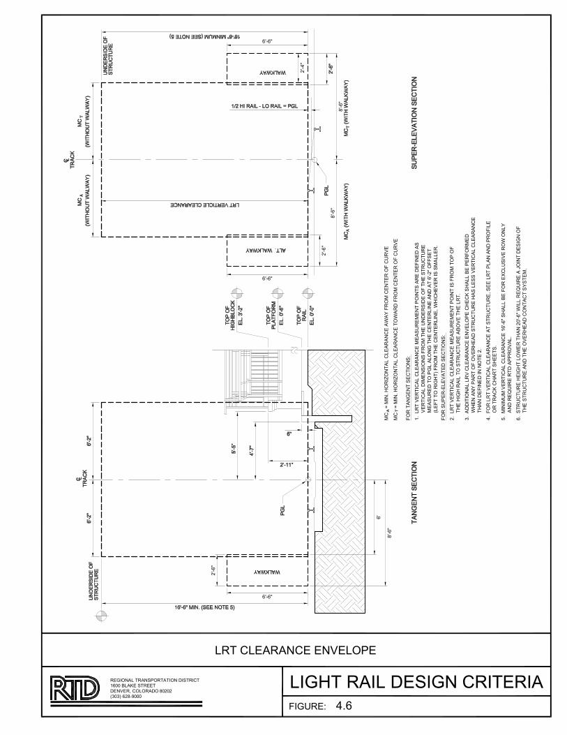
�����
�����
�����
��
�����
�����
��A�BCDEF�B�FC���������C��������F���C���F������
��A�BCDEF�B�FC���������C���F������F���C���F������
�F���C��C�����BFC��
�D�������B���������C�����������C� FBC��������BC����
����B����B��C�BFC���F��E��C����B��F��E����������
���������F ����FC��E���C����BC��C��������F�����
!�����F�B�E�"��F��E���C����BC�#�EB�E����B��������D
�F��� ���������������BFC��
�D�������B���������C�����������C� FBC�B���F��F F�
�E�EB�E��B��F����������$F���E����D
%D���B�BFC�����������C���C���F ��E��&�E���$� ���F����
�E�C�C� ���F�F���E������������E����������B���������C��
�E�C���BC��BCCF���D
'D�F��������B���������C�������������#������ ��C�C� �F�B��
F�����&�E����E����D
(D�BCB�������B���������C���������E���$��F��)����B���F�FC��
�C���*�B������ �F���D
�D���������E�B�E��F����E�C�+�����B����*�B���,FBC����B�CF�
�E�����������C��E�F���E����FC����������D
�����
�����
�����
���'�
�B�����
�B�E���B����B�C��B���B����BFC�����C� F����BFC�B���B��
!%+%"����-+++��C���#�F�F���F�+�+�
��++$��&�������
���������C���C���F �
'D�
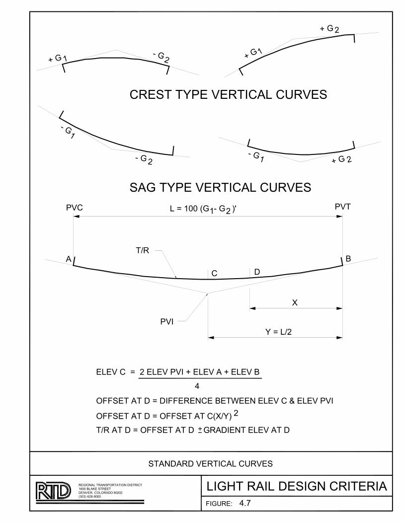
������������AB����������C���DBE��BFB������
��C��C
� � ��C
��C
�
�
��BA�����B��B��D��F�����BA
A�C����B��B��D��F�����BA
��C�
��C�
��C ���C
�
F��������C����C������ �
��D
���� �
� �
�
����F��
������
�AB����������AB����������� �
�AB����������DB�BE�B��B��BBE�BFB���� �BFB����D
BFB����������BFB����D���BFB������BFB����
!
DC��B"
FDC#����DF��BADCE���D�B�D��BCD�E�F����EA������D�E��DA��D��
�$�$��%�&�'����BE�B�(���F������&����
�%����F�)B�A��BB�
A��E������B��D��F�����BA
!*+

������
���
A���B�CD� A���B�CD� ���A�
E�
�D�B��� �D�B���
F������
�����B����B������B����������������B��������������B��������
���� B!DE�"������#��$B��������BE�D�D
�!��B%��&�B������
%��������B����&B�������B�B������B����&
AE
���A�
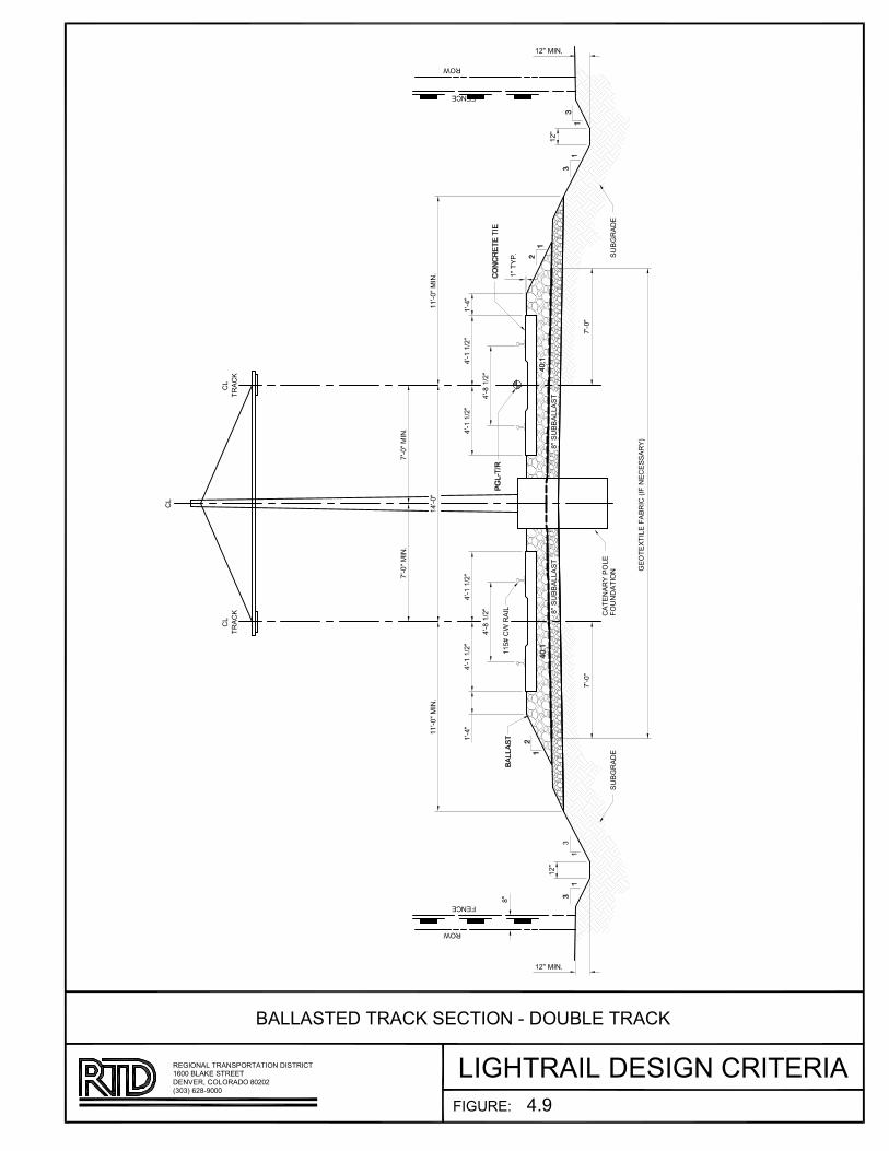
�����
�
�
���A�BA��CD
EF��F
��B
EF��F
��B
��A�����DD���
��A�����DD���
�D
�����
���F����A��DF
E������C��
�D
�D
�����A�C��
�����A�C��
������A�C��
� ����
������A�C��
���A�!"�
���A�!"�
���A�!"�
��� �
#F��F$�CDFAE���C�A%CEA�F�F�����&
�����
�����
���#���F
�"�
�"�
���A�!"�
��A����
���#���F
���A�!"�
���A�!"�
��� �
��
EC#��F'
DC#(���CDA�F�C#�A��C�F�C��F#C���DA�����������C��A�C���C��
%���&A)"��*����F�+F�,A��D�����A��"�"
�)��A�D��FA���FF�
��DD���F�A�����A�F��C��A�A����DFA�����
�*
�"�A�C��
�"�A�C��

�������
���A�B��CD�E��FC���A���B�����FB�CA�BFE���ABA��FCD�EA���A
�����C��������D�F����C�����BD�C�����
����C��B �CEA���A
�FA�FA��FB��!C���AC��BF
"#��
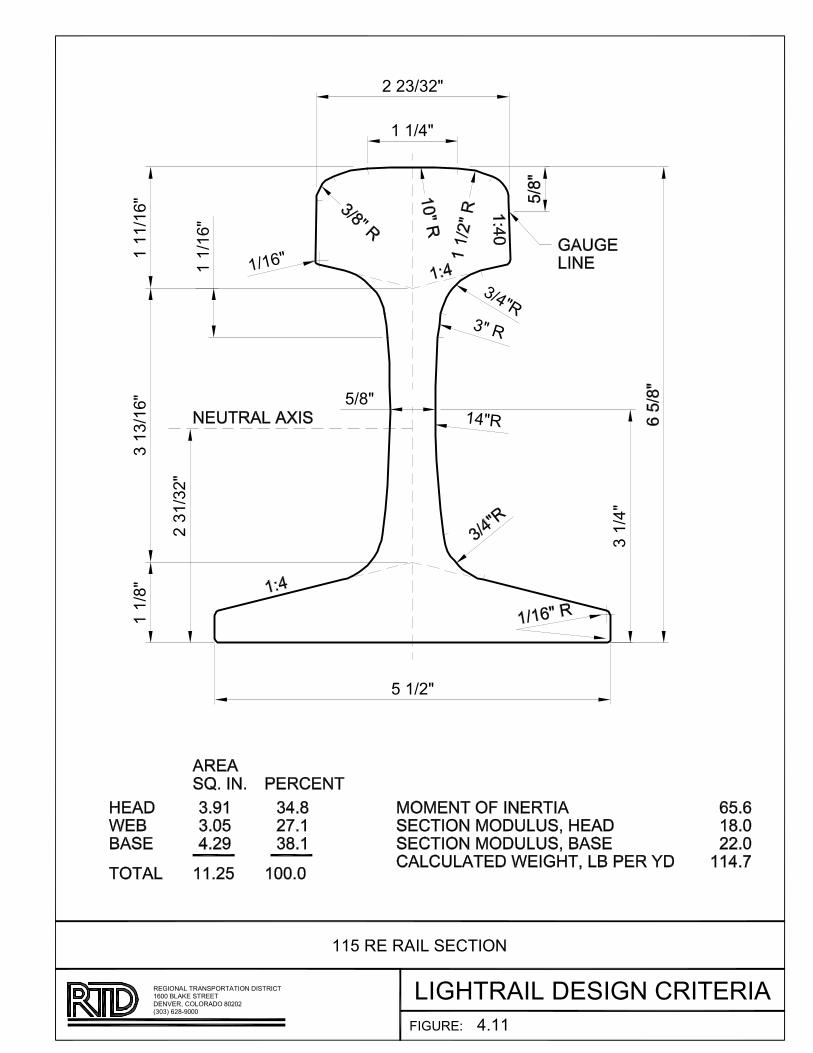
�������
���A�B��CD�E��FC���A���B�����FB�CA�BFE���ABA��FCD�EA���A
�����C��������D�F����C�����BD�C�����
����C��B �CEA���A
��!C��C�B��CE��A��F
"#��
�C��$��%
�$��%
�$"%�
!$�%
�C�$"%
!C�$�%
�C�$�%
�C��$��%
�C��$��%
�C��$��%
�C�$��%
�C�$"%
�"%�
�%C�
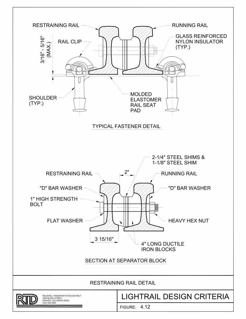
��������AAB��CDE��F��������AAB��CDE
����D�����DB�A���D�D�����DB
�����������CA������������CA�
���CD�C���A��C
CA����CA�����B�����CA�
���B�������DBA
��DB��BD�
����D�����DB�A���D�D�����DB
��D��B����A�A���A�DB
�A�D������A��������B��
!��"����#��"�
$E��%&
E�B�A�AB���EA���DB��A����
�B�����AD�����A���B���D���B���$��%&
�C��B�A�$��%&
�D���A'
BD�C��DB��A�D�����DA�D��A�D���B���������D����D��D�
$!(!&�"���)(((�A��A�*���B�������(�(�
�"((��B� A���AA
�A���D�D�����DB��A�DB
�%��
��
!��#��"�
��B
D�����B�� �
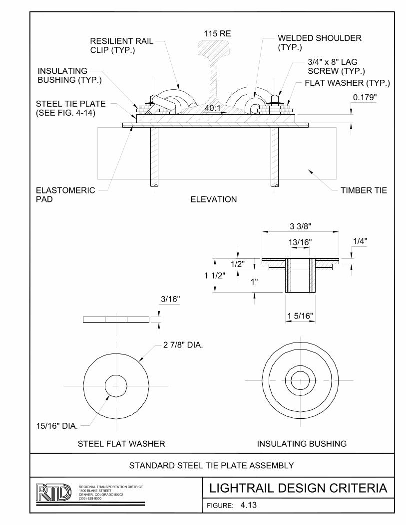
����������ABC�D��E�D���FE�D�
�E���D���F��D������D���
��B
�������D�F�C����E�D���
�E�D���������D�F�C
�D�F�C��E��������E���
�E�F��D�F�C����E���D����E
BB����
����E�D������������D��E��E�D�������
�B� B!"�����
#�$ %"�����
�������
E���D���E�����������D�����������E�D����F��D�D�������D���D
�&�&C�!#%A'���������(���E������%�#�#
B!����E�)���D���D
�D��������D��E�D���FE�D��������E�
�B&
& B!"
��B$'"
& "�*�%"�E��
�E��D������
���������D�F�C
&�& %"
B "B& B!"
B�� B!"
B�B #"
B #"
B"

���������
���
AB
CDEAF��C�B
CFC�AB
���B
C�AB
�E��C�B
�FC��B�B
AB
CFC�C�B
CFC��C�B
�������������
������
��������
�F���B
���B
�FC��B
CC�C�B
C��C�B
��������F������
�!���"
��!������F����!�F����������!�����F�������������F��������
#�$�%F�A�E�$$$������&F��������F�$A$A
C�$$F'��(�F������
��������F�����F���F����F ��F��!F�����F������������
�)C�

�����������
ABC��DEF��
����
�F��
�A�C ����
�DEF�����
�D������
�C
����
�C
����
�C
����
���E����
�C
����
�D�����������D��
�C
����
�����A�C
�� A�!C
�"��A�C
����������#���F
��A�C
����A�C
�$��
E������
�C
ABC��DEF��
����
E�DE����
���%��&
���F������������D�E������������D������D���������D�������E�
'"�"(�!�B) �����D���*�E��������B����
�!���������������
E�����DE���D���������������E���������D����E�
����
E�DE����

�������
���AB�C��BD�E��FB���A���C�����FC�BA�CFE���ACA��FBD�EA���A
�����B��������D�F����B�����CD�B�����
����B��C �BEA���A
A��F��AB����CA��FBE���DE
!"��
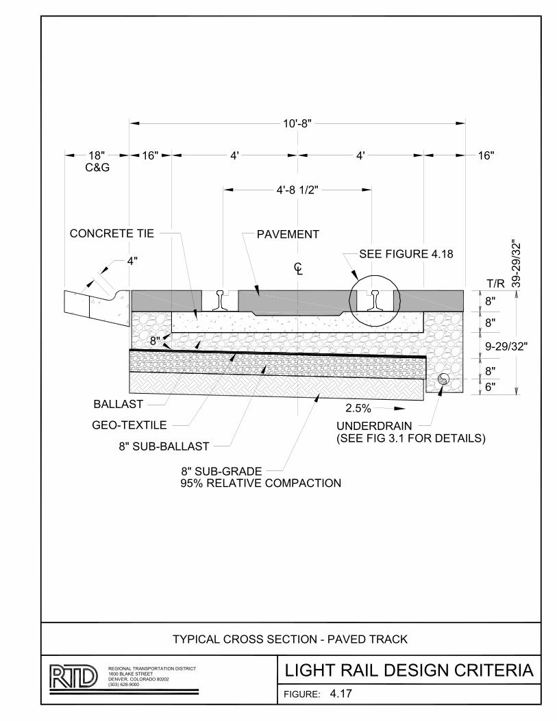
��������
�ABC�D��E��BF����F�E����B�����C���
��B������DD���
��������ED�
��DD���
F��FC���B�E�
F��
FD
���������
����C�C�E�
��A
����B E�B��!B �CB����ED�"
#�
��
���B E��C�B$�!�
��C
��������
��
��
E��C�%
DE�&�BC�EDB���E��BFCE��CE�C��E���DB�C�����C���E��B�E��CEF�
��'�"B#����'''�����C(BF�D�C���B�'�'�
!#''B�D�)�B��C���
�*�EF�DBFC���B��F�E��B�B�����B�C�F)
$�!+
$�
!�� !#� $, $, !#�
!',���
$,��B!���
��
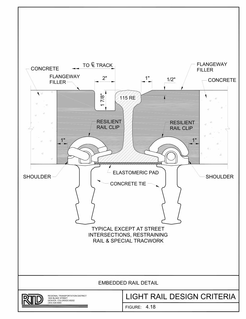
����������A
BCD�E�FD�B�CC��
����C�����D�C��C��
�A
�����C���D��
�AA
��������
BCD�E�FD�B�CC��
���
��A
������
����C�����D�C��C��
�A
����C���
������������
����C���
�����DC��������D��������
�D�C��������DC���D�F�����������������������D����E
B�E����
C�E����D�C�����E���������D��E���DC���D������D�������������
!"!#�$�%&"""���'������C��D����""
�$""�(CD���������
�)(�������D�C����D�C
*+��
�CD���)������D�

Regional Transportation District Section 5 - Station Design Light Rail Design Criteria March 2013
Page 1 of 29
SECTION 5 - STATION DESIGN CRITERIA
5.1 GENERAL .................................................................................................... 3 5.1.1 BASIC GOALS ............................................................................... 3
5.2 SITE PLANNING ........................................................................................... 6
5.2.1 JURISDICTIONAL CODES ................................................................ 7 5.2.2 SITE ANALYSIS ............................................................................. 8
5.3 CIRCULATION AND SITE REQUIREMENTS ....................................................... 9
5.3.1 MODAL INTERCHANGE .................................................................. 9 5.3.2 ACCESS MODES ........................................................................... 9 5.3.3 PARKING......................................................................................12 5.3.4 EMERGENCY EXITING....................................................................12 5.3.5 VERTICAL CIRCULATION/ACCESS………………….……………………….12 5.3.6 HISTORIC PRESERVATION ............................................................ 15
5.4 PLATFORM ARRANGEMENTS ...................................................................... 16
5.4.1 PLATFORMS (CONCOURSE) .......................................................... 16
5.5 TRANSITION PLAZA ................................................................................... 17
5.6 SHELTERS AND FURNITURE.........................................................................18 5.6.1 PASSENGER SHELTERS ................................................................ 18 5.6.2 WINDSCREENS ............................................................................ 19 5.6.3 FURNITURE ................................................................................. 19 5.6.4 SERVICE BUILDINGS .................................................................... 19 5.6.5 MATERIALS AND FINISHES ........................................................... 20 5.6.6 PERFORMANCE STANDARDS ........................................................ 20
5.7 STATION EQUIPMENT..................................................................................22
5.7.1 FARE COLLECTION........................................................................23 5.7.2 EQUIPMENT LOCATION.................................................................23
5.8 COMMUNICATIONS.....................................................................................23 5.8.1 DIRECTIONAL AND WAYFINDING SIGNAGE.....................................23 5.8.2 PLATFORM KIOSK.........................................................................23 5.8.3 STATION LOCATION BLADE SIGNS.................................................24 5.8.4 SHELTER SIGNAGE........................................................................24 5.8.5 EMERGENCY TELEPHONES.............................................................24 5.8.6 CCTV AND VMS (VARIABLE MESSAGE SIGNS) DISPLAYS .................24 5.9 ELECTRICAL SYSTEMS..................................................................24 5.9.1 STANDARDS AND CODES..............................................................25 5.9.2 STATION POWER AND ELECTRICAL SYSTEMS ................................25 5.9.3 SYSTEM VOLTAGES .....................................................................25 5.9.4 SYSTEM CAPACITY...................................................................... 25 5.9.5 PERFORMANCE STANDARDS.........................................................26
Regional Transportation District Section 5 - Station Design Light Rail Design Criteria March 2013
Page 2 of 29
5.9.6 STANDARD ELEMENTS..................................................................26 5.9.7 ILLUMINATION LEVELS..................................................................26 5.9.8 STATION SITE LIGHTING...............................................................28 5.9.9 VEHICULAR ACCESS LIGHTING......................................................28 5.9.10 PEDESTRIAN ACCESSWAYS LIGHTING..........................................28 5.9.11 PLATFORM LIGHTING..................................................................28 5.9.12 CONTROL OF LIGHTING SYSTEMS ...... ........................................28
Regional Transportation District Section 5 - Station Design Light Rail Design Criteria March 2013
Page 3 of 29
SECTION 5 - STATION DESIGN CRITERIA
5.1 GENERAL
These criteria are intended to direct the selected Design Engineers in the design and preparation of light rail transit (LRT) station contract documents.
These criteria have also been established to enhance the safety and quality of the LRT system, which has a fundamental impact on the ability to attract and sustain patrons.
A LRT station comprises site access, parking (multi-modal access), transition plaza, platform (concourse), tracks and all appurtenances necessary to provide for the public safety, protection from the elements and public information. The station also serves as a gateway in and out of a community as the origin/destination source of passenger traffic.
See figures 5.1 through 5.5 for various platform configurations.
5.1.1 BASIC GOALS
The goals for this Design Criteria were derived from a rigorous evaluation and review of the station design for other transit agencies as well as lessons learned through RTD past projects. These goals provide the basis for decisions and will be used to evaluate designs for new and renovated facilities.
The goals are presented in several categories: Inter-Modal Function, Alignment, Architecture, Station and Community Relationship and Basic Design Objectives are applicable to all sections of this section.
5.1.1.1 INTER-MODAL FUNCTION
Inter-Modal Functions are defined as bus automobile, bike and pedestrian means of travel to the station.
• Provide a safe, efficient and convenient configuration for inter-modal transfer at the station.
• Provide clear and easily understood transit information that can be referenced quickly and that minimizes disorientation.
• Develop operational efficiencies that simplify modal interchange and passenger processing.
• Minimize congestion and LRT crossings of inter-modal functions.
• Provide the best service possible at a reasonable cost.

Regional Transportation District Section 5 - Station Design Light Rail Design Criteria March 2013
Page 4 of 29
5.1.1.2 ALIGNMENT
• Follow FTA TCRP Report 155, Track Design Handbook for Light Rail Transit, applicable AREMA standards, FRA guidelines for track geometry and Section 4 of this Design Criteria.
• Adhere to AREMA and FRA guidelines for at grade and grade separated LRT crossings.
• Locate stations on horizontal and vertical tangent sections.
• Coordinate track alignment and at grade/grade separated crossings with CDOT and local agencies, i.e. planning departments, traffic and emergency access.
5.1.1.3 ARCHITECTURE
In general, on corridors with existing light rail, the extension design should match the existing architectural elements. On new alignments architectural elements should be standardized to the extent possible:
• Create a civic architecture that is permanent, functional and pleasant, has a LRT character and contributes to its context -- one that is not entirely a derivative of the transit system, but of the neighborhoods and community of which it is a part, yet maintains an overall line recognition and system identity.
• Develop a family of station parts and furniture that are interchangeable and allow for the individual character of each neighborhood or community as appropriate.
• Protect transit passenger from adverse weather conditions (snow, rain, wind and summer sun) and vehicular traffic. Provide seating at shelters and other protected locations on the platform.
• All designs must conform to International Building Codes, ANSI 117.1, and ADA standards for accessibility design, and current editions and other applicable codes.
• Make transit a safe, secure, friendly and enjoyable experience and accessible to all, including the disabled.
• Develop systems that use maintainable materials and minimize life cycle costs.
• Provide an architectural and urban design framework that defines and encourages joint development opportunities.
Regional Transportation District Section 5 - Station Design Light Rail Design Criteria March 2013
Page 5 of 29
5.1.1.4 STATION
Stations consist of three elements; platform (concourse) area where passengers walk to and from the trains and where passengers queue in anticipation of boarding trains. The transition plaza is a space necessary to facilitate the movement of patrons from the parking areas or other means of access (modal access) to the platform and from the platform to their modal access. The multi-modal access is defined as the choice of transit used by a patron to access the station, i.e. car, bus, bike or walk. The basic design criteria for stations are as follows:
• Meet setback from centerline of track and dynamic envelope requirements for clearances at the platforms.
• Meet requirements of ADA, ADAAG and ANSI 117.1, NFPA 130, and Part IV DOT, 49 CFR Parts 27, 37 and 38.
• Adhere to FRA AREMA and TCRP Report 155 governing railroads and RTD guidelines for platform safety requirements.
• Minimum platform and transition plaza areas are defined by the crush load of the train consist x2 x5 sf.
• Coordinate platform and transition plaza with bus, kiss-n-ride, park-n-ride, pedestrian and bike access.
• The transition plaza is a space described as an area necessary to facilitate the movement of patrons from the parking areas or other means of access to the platform. The transition plaza is where patrons can obtain tickets, view public information systems and wait for pick-up. In many instances the transition plaza also acts as a side loading platform, and should be held to the same clearance and lighting requirements as a platform.
• Coordinate platform and transition plaza design with neighboring community. Community involvement is necessary to establish a sense of place of the station in the community and to develop a design for shelters, windscreens and other elements. Standardizations of amenities should be encouraged. As a part of the community development, RTD, its design team and community planners could facilitate a plan to develop transit-oriented development (TOD) adjacent to the mass transit site. This is only viable if, the governing body has zoning ordinances in place that allow a mixed use TOD to occur. TOD however needs to occur with a balance toward providing a convenient and pleasant experience for the transit user as well as providing opportunities for mixed use development.

Regional Transportation District Section 5 - Station Design Light Rail Design Criteria March 2013
Page 6 of 29
5.1.1.5 COMMUNITY RELATIONSHIP
• Protect, maintain and enhance existing qualities which are valued.
• Promote desirable TOD.
• Recognize emerging development that can complement station development and increase ridership.
• Initiate and coordinate programs with the community that limit local traffic impacts and minimize disruption during and after the implementation phase.
• Utilize local jurisdictional processes and agencies throughout project design and implementation.
• When budget allows, encourage implementation of an Art-at-the-Station program to instill a sense of ownership by the community and a sense of “place” for the station in the community and as a recognizable feature along the corridor.
5.2 SITE PLANNING
The purpose of this section is to describe the system-wide design philosophy for station layout and related site development. The facilities to be designed shall address the following:
• Rail track way – use existing commercial railroad ROW or public ROW where possible. Keep consistent with system goals and objectives.
• Rail platforms – develop on tangent sections of track, linear progression from train to platform to transition plaza to multi-modal means of station access.
• Bus and auto roadways – primary multi-modal means of accessing station. Coordinate with local traffic patterns and segregate from secondary multi-modal means of access. It is also necessary to separate bus and automobile traffic, particularly as they enter and exit the park and ride and move through the park and ride.
• Pedestrian walkways – coordinate with local jurisdictions for connections to existing or planned pedestrian access ways; segregate from motorized vehicles.
• Bicycle paths – coordinate with local jurisdictions for connection to existing and proposed bicycle access ways, segregate from motorized vehicles. Bicycle paths shall not cross platforms at grade and shall be separated from platforms with a barrier when parallel.
• Auto and taxi drop off and waiting zones - Coordinate through RTD Design Guidelines and Criteria for Bus Transit Facilities.
• Parking lots/structures – elements that are determined by ridership and available land use and ownership. RTD Design Guidelines and Criteria for Bus Transit Facilities shall be used as a reference for the overall design. Coordinate through local jurisdiction for parking lot requirements.

Regional Transportation District Section 5 - Station Design Light Rail Design Criteria March 2013
Page 7 of 29
• Shelters – passenger shelters shall be designed to reflect the context of the overall urban design of the corridor and the neighborhoods that are adjacent to the station. Bus shelters shall be a standard design shelter provided by RTD.
• Landscaping – is used to enhance the overall aesthetic value of the station. Landscaping can be used to define the boundary from multi-modal access to the transition plaza and from the transition plaza to the platform. Landscaping shall not impede visibility of the platform areas or create hiding spaces or security barriers. At the transition plaza landscaping can be used to define edges, direct pedestrian traffic, provide shade and separate the transition plaza from the platform. Generally landscaping shall not be included on the platform (concourse).
• Elevators, escalators, ramps and stairs – Site selection should serve to eliminate the need for vertical circulation. In cases where this is not possible, follow local jurisdictional agencies regulations, RTD standards and practices, building codes; IBC, ADA, ADAAG, ANSI 117.1, NFPA 130, 101, ASME A17.1 and other applicable codes and standards. At a minimum elevator shafts and cars shall have three sides, or two sides when prevalent site conditions apply with the approval by the Safety Committee, that are transparent the full length of travel and full height of the car.
• Site Furnishings - Bicycle lockers/racks, benches, see through trash receptacles, fare collection equipment, newspaper racks, etc. shall be standardized for each corridor to provide a uniform appearance and for ease of maintenance and replacement. Bicycle lockers, news racks, trash receptacles and other publicly accessible receptacles shall meet the security requirements in section 14.15 Publicly Accessible Receptacles.
• Driver Relief Station (restrooms) – drivers’ restroom facilities shall be located in an area that is both convenient for the train operators and the bus operators. These facilities are not open to the general public. Buildings shall be constructed of durable materials with a low possibility of replacement needs. Building design shall follow standard layout for restroom facilities in RTD Standard Plans. End of the line facility shall be large Driver Relief Stations as shown in the Standard Plans. All facilities shall utilize approved card reader system for access.
• Signage shall be per ADA standards for accessibility and way fare in accordance with RTD Rail System signage standards.
These elements are to be located at each station site in a manner that is functional, safe, easily maintained and attractive to passengers and neighboring residents.
5.2.1 JURISDICTIONAL CODES
The nature of LRT causes its alignment to travel through numerous districts, cities, and counties. Each of these legally defined areas has different land use and development regulations and legislative procedures directly affecting station site planning and design. Each individual jurisdiction may have special amendments or supplements to codes and standards that apply on a statewide and national basis. Therefore:

Regional Transportation District Section 5 - Station Design Light Rail Design Criteria March 2013
Page 8 of 29
• Identify the governing jurisdiction for each site at every governmental level.
• Locate jurisdictional boundaries. • Review applicable adopted master plans and municipal codes. • Use the latest edition of the following:
o International Building Code o Fire protection codes o State of Colorado "Building Regulations for Protection from Fire
and Panic." o Americans with Disabilities Act Accessibility Guidelines for
Buildings and Facilities (ADAAG) o Americans with Disabilities Act Accessibility Guidelines for
Transportation Vehicles o "Standards for Accessible Transportation Facilities",
• ANSI 117.1 • ADAAG • NFPA 130 101 • AREMA • FTA
o Rail Agency requirements when applicable.
In general, station facilities should be designed to meet all requirements of all applicable federal, state, and local codes and regulations. Codes shall be analyzed with regard to this Criteria Manual, the governing jurisdictions interpretation and the code that provides the most stringent application for the public good.
5.2.2 SITE ANALYSIS
Site analysis is the process in which the characteristics of a potential station site are gathered together. Typical physical characteristics to be evaluated are:
• General circulation and access • Context
o Views to and from the site o Weather conditions o Topography o Existing infrastructure and building improvements o Land use o Existing vegetation o Drainage o Solar orientation o Traffic counts
• Soils information • Existing utilities
Regional Transportation District Section 5 - Station Design Light Rail Design Criteria March 2013
Page 9 of 29
5.3 CIRCULATION AND SITE REQUIREMENTS
Each mode of transportation has specific circulation and operational requirements. While each mode has its own unique characteristics, it is recognized that all modes must respect and enhance the operation and access of other modes that interface in and around rail transit facilities.
Underlying site requirements that support transit such as parking, furnishings, operating equipment, shelters, and landscaping provide convenience, comfort, accessibility and an enhanced quality of life for transit passengers and employees.
Performance standards based on design objectives shall be the basis for all design decisions. They provide the fundamental framework for resolving the inter-relationship between each of the station activities and the means for minimizing conflicts and maximizing efficiency.
Above is a broad description of circulation and site requirements, it and the following descriptions need to be developed with the use of the RTD Design Guidelines and Criteria for Bus Transit Facilities
5.3.1 MODAL INTERCHANGE
Modes are the means that passengers and employees access LRT stations. Typical access modes considered in these criteria are:
• Light Rail Transit (LRT)
• Bus
• Walk
• Bicycle
• Automobile
• Commuter Rail
There are distinct differences between each mode in terms of maneuverability, safety, speed, visibility, space requirements, compatibility, and reliability. The following describes the basic characteristics for each mode.
5.3.2 ACCESS MODES
LRT is a more predictable and confined form of transit in that it operates within a semi-exclusive ROW.
Passengers tend to arrive at or near the scheduled LRT departure time and do not spend a lot of time waiting. Therefore, modal interchange becomes a key consideration in station design.
Regional Transportation District Section 5 - Station Design Light Rail Design Criteria March 2013
Page 10 of 29
5.3.2.1 BUS ACCESS
The bus system will be integrated with LRT and provide feeder routes to station facilities. Where applicable, there will be a hierarchy of vehicular modes of access, giving priority to feeder buses. The following are general criteria that will help guide the site planning process:
• Buses should be able to get as close to LRT transition plazas as possible with a maximum walking distance of 400 feet to the platform.
• Eliminate situations where buses are required to cross LRT tracks.
• Make provisions to provide emergency bus service in the event of an LRT system failure.
• Bus and automobile access should be separated wherever possible.
• Minimize conflicts between buses, trains, automobiles, bicycles and pedestrians.
5.3.2.2 WALK ACCESS
Good pedestrian circulation to, from, and across train platforms is essential for the smooth and safe operation of stations. Circulation patterns should be as simple, obvious, and comfortable as possible. Some of the points that warrant careful review for applicability and consideration in achieving good pedestrian orientation and circulation follow:
• Avoid unnecessary turns and dead ends.
• Pedestrian access from bus, kiss-and-ride and park-and ride areas must be as clear and as simple as possible.
• Circulation elements shall use color, texture and sight distances to increase visual pleasure, guidance, patron safety and security.
• Provide adequate space to avoid bottlenecks.
• Avoid cross-circulation at fare collection and decision points. Generally provide right-hand circulation.
• Provide well lit pedestrian walkways.
• An obstruction free zone for pedestrians shall be maintained on all loading and unloading transit platforms. This obstruction free zone shall meet all requirements of The American’s with Disabilities Act, NFPA 130, and all applicable standards and codes for passenger safety and

Regional Transportation District Section 5 - Station Design Light Rail Design Criteria March 2013
Page 11 of 29
movement. No obstruction shall be placed within 7’6” of a vehicle door on the platform.
• Provide adequate space so that queues at fare collection areas do not block traffic.
• Provide separate facilities, where feasible, for entering and leaving the station.
• Locate passageways, shelters and stairways to encourage balanced train loading and unloading. Passengers tend to board at such connection points on the platform.
• Provide ramps and elevators as required for disabled patrons. Walkway, highblock and structural access ramps shall meet ADAAG.
• Grade changes are to be minimized, and where necessary they shall conform to slope criteria for disabled access.
• Cross flows, dead ends, and turns greater than 90 degrees are undesirable for both patron security and circulation.
• Circulation shall be designed to provide ample space adjacent to, but out of the mainstream of, pedestrian flow. This will accommodate for disabled, infrequent or waiting patrons.
• Surge and queuing spaces shall be provided ahead of every barrier and change in circulation, direction, or mode.
• Obstructions such as telephone booths, pylons, advertising displays, coin changers, concessions, seating or maps are not allowed within the passenger through zone.
• Shelter elements shall have sufficient transparency to provide adequate visual surveillance of the station area to discourage vandalism and enhance patron safety.
• Provide adequate sight distance and visibility along pedestrian routes.
• Provide track crossing clear of LRT vehicles for platform exiting.
• Provide a minimum of two points of access/egress from the platform that meet the requirements of NFPA 130.
5.3.2.3 BICYCLE ACCESS
Those passengers arriving by bicycle shall be accommodated in the safest and most inviting manner possible. Except at the downtown Denver stations, space shall be provided for racks for at least 10 bicycles if possible at every station. These facilities shall be located to minimize conflicts with pedestrian and vehicular traffic, make the most effective use of roadways and curb cuts, and reduce the need for special graphics. To promote

Regional Transportation District Section 5 - Station Design Light Rail Design Criteria March 2013
Page 12 of 29
security, bicycle storage areas should be visible from the street or station entrance. Where possible, bike racks and lockers should be located on the transition plaza and segregated from large group gathering areas. No bike racks or lockers are to be located on the platform (concourse).
5.3.2.4 AUTO ACCESS
Auto access shall be provided in a manner that meets all state and local codes and does not interfere with access modes of higher priority.
5.3.3 PARKING
Reference the RTD Design Guidelines and Criteria for Bus Transit Facilities
5.3.4 EMERGENCY EXITING
Design Objectives
• Any fully loaded station platform shall be able to be evacuated in accordance with NFPA 130.
• Two exits is a requirement of NFPA 130, RTD cannot approve a variance to NFPA 130, only the authority having jurisdiction (the fire department) can grant an NFPA 130 variance.
5.3.5 VERTICAL CIRCULATION / ACCESS
5.3.5.1. INTRODUCTION
The design of elevators shall incorporate the design criteria for all related systems. The elevator design and installation shall comply with the latest editions of applicable Federal, State, and Local Building, Security, Fire, and Life Safety Standards and Codes. These include, but are not limited to ASME A17.1 Safety Code for Elevators and Escalators and ASME A17.5 Elevator and Escalator Electrical Equipment. Elevator repairs, installations, and inspections are also governed by the Colorado Department of Labor and Employment, Division of Oil and Public Safety, Elevator and Escalator Certification Act, Title 9, Article 5.5, Sections 1-7, Colorado Revised Statutes. For Federally funded projects, the procurement of equipment must comply with CFR Title 49 Part 661.5 Buy America Requirements, or as amended.
The designer shall coordinate with other discipline professionals to deliver an integrated design to RTD. The commissioning procedure shall include the
Regional Transportation District Section 5 - Station Design Light Rail Design Criteria March 2013
Page 13 of 29
operation of all communication interfaces and controls. The equipment shall be fully functional prior to state inspection. 5.3.5.2. ELEVATOR PLACEMENT
The use of elevators at RTD transit facilities other than parking structures shall be considered only after other design options have been evaluated. Project designers shall first consider ramps within existing right-of-way. The need for right-of-way acquisition or use of elevators shall be coordinated with RTD. A minimum of two elevators may be required at each vertical conveyance location.
Prevailing winds shall be studied for each location to determine the orientation of the elevator doors. If possible, elevator doors shall be oriented on the leeward side.
5.3.5.3. ELEVATOR SAFETY AND SECURITY, AND EMERGENCY NEEDS
Hoistways and cars must be transparent on three sides so that security personnel can see inside. The RTD Safety and Security Division may grant a variance to have only two sides of the hoistway and car be transparent. Security cameras shall be installed inside all elevators cars. See Section 14, System Safety and System Security, RTD Light Rail Design Criteria for other requirements.
Emergency measures shall be satisfied by coordinating with jurisdictional authorities, and complying with applicable codes and regulations.
5.3.5.4. ELEVATOR CAR
Elevator car sizes shall be in accordance with the standards established by the National Elevator Industries, Inc. (NEII). Elevator car shall be of such a size and arrangement to accommodate an ambulance gurney 24-inch by 84-inch with no less than 5-inch radius corner, in the horizontal, open position.
The car shall be made from rust proof, non-organic, and non-porous materials. Provision shall be made to drain liquids that get into the elevator car through the elevator floor, by channelizing it in a manner that does not affect the operation of the elevator.
The door frames of the car shall be of stainless steel. Doors shall be of hollow reinforced metal. The subfloor shall be made of non-absorbent materials or shall be sealed. Floor finishes shall be nonslip even when wet. Acceptable flooring option is diamond patterned aluminum. Floor seams shall be welded. Cars shall be vented with fans. Conditioned air shall be
Regional Transportation District Section 5 - Station Design Light Rail Design Criteria March 2013
Page 14 of 29
allowed with RTD approval. Lighting in car shall be vandal resistant, and satisfy camera operation needs.
5.3.5.5. MINIMIZE SNOW, ICE, AND DEBRIS TRACKING AND ACCUMULATION
Provisions shall be made to reduce snow, ice, and debris tracking into the elevator car and door track. The landing outside the car shall be graded to drain away from the car, in a manner that complies with ADA. Electrically heated slabs at each landing door are permitted. Heating areas shall be one-foot wider on each side of the car door, and at least eight feet long, and be designed per manufacturer recommendations. Other options require RTD approval. 5.3.5.6. HOISTWAY
Hoistway shall be water tight, fan ventilated, and maintained so that elevator equipment can function within required tolerances. Conditioned air shall require RTD approval. Interior ledges in the hoistway created by structural elements and glass mullions shall not exceed four inches. Only elevator equipment conduits are allowed within the hoistway; provision shall be made to route all other required conduits outside the hoistway. Attempt shall be made to consolidate outside conduits in chases.
Laminated safety glass panels shall be used. The panels shall be of a size, weight, and dimension that can be lifted by one person. The aspect ratio of panels may vary. The use of tinted or insulated glass, and low emissivity coatings shall be considered to reduce the solar heat gain. Limited and judicious placement of opaque materials shall require RTD approval.
The designer shall design for applicable smoke venting requirements. All openings in the hoistway shall be designed to prevent water entry. Hoistway doors and frames shall be of brushed stainless steel.
5.3.5.7. SUMP PIT
The elevator pit shall be shall be designed to prevent water infiltration. RTD preference is to drain elevator pit into a holding tank installed in a location accessible by RTD Facility Maintenance, who will periodically empty it. SCADA or other monitoring system connection for float sensor will be required. Appropriate lighting, as required, shall be provided. 5.3.5.8. ELEVATOR MACHINE ROOM
Provide watertight and conditioned, machine room with required light, in proximity to the hoistway, to meet the requirements of the elevator

Regional Transportation District Section 5 - Station Design Light Rail Design Criteria March 2013
Page 15 of 29
manufacturer. Any MEP equipment, if installed outside, shall be protected from vandalism.
5.3.5.9. COMMUNICATION SYSTEMS
The elevator communication system shall be designed to work with RTD’s communications system. RTD has separate systems that monitor various facilities. The designer shall ensure that the emergency systems in the elevator car are connected to a 24-hour RTD monitored location. The elevator car shall accommodate the physical mounting of a hands-free GAI-Tronics (or approved equal) phone system. Each car shall have a unique identifier, as required by RTD security. Communication power and communication data conduit and junction boxes shall be separated from each other. Separate space, other than elevator machine room, shall be provided for the SCADA and/or telecommunication system interface.
5.3.5.10. SPECIFIC DESIGN REQUIREMENTS
a. The elevator controller shall provide for the automatic descent/ascent to the closest landing, during a power outage or malfunction.
b. Provide electrical outlet at each elevator landing for maintenance equipment. c. Elevator systems and components shall be designed for maximum life
cycle benefit. d. Elevators shall be of non-telescoping hydraulic or traction type. e. RTD prefers that the elevator control system be non-proprietary, and not
require external proprietary software and/or equipment. Equipment and component systems shall exclude any experimental devices and/or proprietary designs that could hamper and/or otherwise prohibit subsequent maintenance repairs or adjustments by all qualified contractors. Other systems require RTD approval.
f. The designer shall submit calculations for sizing of mechanical and climate control equipment for review by RTD prior to finalizing the design.
5.3.6 HISTORIC PRESERVATION
At the beginning of the station siting process, potential applicability of requirements of the Historic Preservation Act and Section 4(f) of the Transportation Act of 1966 should be addressed.
Where LRT stations may affect historical areas or structures, potential impact zones should be identified. These would include areas where station placement would block views or interfere with pedestrian circulation and access.
Regional Transportation District Section 5 - Station Design Light Rail Design Criteria March 2013
Page 16 of 29
If joint use were to be planned, the Design Team should develop a design program which identifies those agencies or citizen groups which are likely to be involved and the procedure to be followed for approach of design. The program should also identify significant architectural features which should be taken into account in station and site design.
If a portion of a historic structure is to be retrofitted to accommodate an LRT station, security and safety features necessary to preserve the significant historic characteristics of the structure should be incorporated into the station design. Approval from SHPO is required.
5.4 PLATFORM ARRANGEMENTS
Three alternative platform arrangements for on-line stations exist as follows:
• Side Platforms - Side platforms are located directly opposite one another, each servicing one mainline track.
• Center Platform - Single platform to service tracks located on each side of the platform.
• Side Center Platform – Side platform located on one side only and a center platform to service the other tracks.
5.4.1 PLATFORMS (CONCOURSE)
The following presents fundamental criteria that are intended to produce efficient and passenger-sensitive platforms.
• All platforms shall be designed to conform with the ADAAG, including detectable warning strips on platform edges.
• Platform length for both center and side platforms shall accommodate a four-car train, unless approved by RTD.
• The nominal horizontal gap between the platform edge and the edge of vehicle floor shall be 6 inches. On tangent tracks, the platform edge is located 55 inches from track center line with a tolerance of +0.50 inches vertically and 0.0 inches horizontally.
• The platform height at the edge of platform face shall be 6 inches above the top-of-rail profile. When stations are located on or within streets or existing sidewalks, consider the crown of the street when calculating the platform height.
• Minimum platform width for side platforms shall be 16 feet with 21 feet preferred.
• Minimum width for center platforms shall be 16 feet with 21 feet preferred.
• Platforms must be located on tangent tracks.
Regional Transportation District Section 5 - Station Design Light Rail Design Criteria March 2013
Page 17 of 29
• Cross slopes shall not exceed 2% with a minimum of 1% and the maximum longitudinal slope shall be no more than 1% unless approved by RTD in writing.
• Mechanical and electrical equipment shall be placed in vertical surfaces, rooms or underground to reduce obstructions. Consider maintenance implications for each piece of equipment prior to underground placement.
• Provide clear emergency exiting from platforms.
• Concentrate fixed objects such as furniture, signage, shelters, etc. within a furniture zone while maintaining adequate distance between elements for circulation. Keep as much of the platform clear of fixed elements as possible.
• The track area between platforms shall be covered or paved at designated pedestrian crossings only.
• Platforms and station exits shall be sized and located to accommodate the estimated or expected volume of passengers as defined by NFPA 130 Occupant Load.
• Exits shall provide safe exiting from trains and platforms under normal operational and emergency conditions. Platforms and exits shall be sized to allow passengers to completely clear the platform prior to the arrival of the next train.
• Secondary access or exit points should be provided, make them visible, inviting and safe.
• Barriers should not trap anyone between the LRV or vehicular traffic.
• Where possible, provide clear and unobstructed diagonal pedestrian access across platforms wherever modal interchange occurs.
• Platforms shall be provided with a source of water for cleaning and maintenance purposes.
• Any electronic passenger information systems such as variable message signs shall be located to maximize visibility to passengers while minimizing obstructions.
5.5 TRANSITION PLAZA
The transition plaza is a space described as an area necessary to facilitate the movement of patrons from their multi-modal access to the platform. The transition plaza is where patrons can obtain tickets, view public information systems and wait to be picked up.
The following are basic design criteria;
• Design to conform to ADA standards and code requirements (see subsection 5.2.1)
• Provide easy access to Ticket Vending Machines (TVM), stand alone validating machines (SAV), information technology and public communication systems without impeding the flow of patrons to the platform.

Regional Transportation District Section 5 - Station Design Light Rail Design Criteria March 2013
Page 18 of 29
• TVM, SAV and information systems and other furnishings must be located adjacent to the line of travel without impeding the pedestrian flow. All vending machines must be oriented away from direct sunlight.
• Preferably vertical circulation needed to reach the platform shall be constructed on the edge of the transition plaza and the platform. When ROW and site design constraints cause vertical circulation elements to be placed on the platform, the design should follow ADAAG requirements for minimum circulation space.
• Existing requirements from the plaza are the same as the platform; follow NFPA 130 2-5.2 and 2-5.3.
5.6 SHELTERS AND FURNITURE
These criteria have been developed as a technical guide to safe and efficient station design while promoting community pride. Stations are the public focus of the rail system in that they are central to modal interchange and serve thousands of passengers on a daily basis. It is key to the operation of the entire transit system that station platforms are easily understood, friendly and efficient for passengers. Station design should not only consider the functional and operational efficiencies, but also integrate humanistic and community spirit into the design.
5.6.1 PASSENGER SHELTERS
The following is a list of objectives that LRT, bus, and kiss-and-ride shelters should achieve:
• Provide passengers with comfort and protection from expected adverse weather conditions -- snow, rain, wind and summer sun.
• Provide identity for the station as well as the surrounding area.
• Provide a feeling of security and means of surveillance.
• Help provide adequate lighting.
• Utilize materials and construction practices that minimize maintenance requirements.
• Utilize materials and construction practices that minimize life cycle costs.
• Standardize materials and construction practices.
• Utilize materials and construction practices that are compatible with existing RTD facilities.
• Arrange and articulate shelters to create an enjoyable experience.
• Height of Shelter protective edge should be no greater than 10 feet 4 inches or eave height to match height of window head of passenger car.
• Typical shelter arrangement is for each platform to have a 60’ main shelter, and a 30’ shelter over each highblock. Location and length of shelters ultimately to be determined by large ridership, local

Regional Transportation District Section 5 - Station Design Light Rail Design Criteria March 2013
Page 19 of 29
jurisdiction requirements and the potential for a shelter to tie into TOD.
• Width of shelters shall not infringe on the dynamic envelope for the rail cars. A minimum width is 12 feet is desirable
• High block platforms shall be protected by canopy.
• Shelters and Canopies shall be designed for a minimum wind speed of 100 mph.
5.6.2 WINDSCREENS
The following is a list of criteria for windscreens:
• Maximum height 6 feet 8 inches.
• 75% of the surface area must be translucent or transparent.
• Overall width depends on flow of pedestrians and location of the screen.
• Place where most effective in blocking prevailing winds.
• Provide a minimum of one bench on the lee side of the windscreen.
• Comply with ADAAG for access and circulation around the windscreen.
5.6.3 FURNITURE
The following is a list of furniture to be used at the stations:
• Newspaper racks by RAK systems or approved equal. Newspaper racks shall be placed according to security requirements outlined in section 14.15 Publicly Accessible Receptacles.
• Bicycle lockers/racks are not to be placed on the platform, only on the transition plaza or the park-n-ride. Bicycle lockers shall be placed according to security requirements outlined in section 14.15 Publicly Accessible Receptacles.
• Provide a minimum of 4 benches per platform. Bench quantities and arrangement in transition plazas shall be determined by size of the space and function.
• Trash receptacles are not to be placed on the platform, only on the transition area away from locations where large groups may gather. Trash receptacles shall be placed according to security requirements outlined in section 14.15 Publicly Accessible Receptacles.
5.6.4 SERVICE BUILDINGS
Service buildings are defined as all structures not open to passengers, but which need to be accessible to RTD employees or contractors. Design of service buildings at stations shall comply with NFPA 130.
Regional Transportation District Section 5 - Station Design Light Rail Design Criteria March 2013
Page 20 of 29
• Equipment Rooms - Signal, electrical and communication rooms shall be sized according to the requirement identified by RTD Systems Engineering. Location to be coordinated with Systems Engineering, Operations and the Station Design Team. Equipment rooms shall not be located on station platforms.
• Driver Relief Station - Driver relief stations (DRS) are to be provided at stations where they can be used by both bus and LRT operations. No access will be provided for public use. Generally, driver restrooms will be located in association with larger park-n-rides or at the end of line stations.
5.6.5 MATERIALS AND FINISHES
The quality and character of station materials utilizing simple, durable materials has a direct effect on maintenance requirements and the image of each facility. Simple, durable materials in minimal sizes with long-standing availability, installed to facilitate replacement can diminish damage and maintenance while balancing the character and visual quality of each station. Because vandalism tends to breed upon itself, materials should be used such that repair time is reduced and stations never appear underused or abandoned.
In specifying manufactured items or materials, preference shall be given to standard off-the-shelf items available from more than one supplier over custom-made or single-source items. In specifying finish, size, color, pattern or composition, slight variations in appearance should be allowed so less costly products or materials of equal quality can be utilized.
5.6.6 PERFORMANCE STANDARDS
5.6.6.1 DURABILITY
Durable and cost-effective materials shall be used that have consistent wear, strength and weathering qualities. Materials shall be capable of good appearance throughout their useful life and shall be colorfast.
5.6.6.2 LOW MAINTENANCE
Life cycle maintenance costs should be considered in the evaluation of all materials and finishes.
5.6.6.3 QUALITY OF APPEARANCE
Materials should be appealing and harmonious in appearance and texture. They should reinforce system continuity while relating to the local context.
Regional Transportation District Section 5 - Station Design Light Rail Design Criteria March 2013
Page 21 of 29
5.6.6.4 CLEANING
Materials that do not soil nor stain easily shall be used and shall have surfaces that are easily cleaned in a single operation. Minor soiling should not be apparent. Commonly used equipment and cleaning agents should be able to be utilized. All porous finishes subject to public contact shall be treated or finished in a manner that allows easy removal of "casual vandalism."
5.6.6.5 REPAIR OR REPLACEMENT
To reduce inventory and maintenance costs, materials shall be standardized as much as possible for easy repair or replacement without undue cost or disruption of LRT operation. For example, hose bibs, electrical outlets, lighting fixtures and lamps, glass or plastic lights, information panels, signs, shelter materials, etc., shall be standardized on commonly available sizes and finishes for easy inventory stocking and installation.
5.6.6.6 NONSLIP
Entrances, stairways, platforms, platform edge strips, and areas around equipment shall be high nonslip properties. Floor finishes shall be nonslip even when wet. This is particularly important at stairs, elevators and other areas near station entrances, as well as platform areas.
5.6.6.7 CORROSION RESISTANCE
Because of moisture and the electrical currents involved in transit operation, special consideration must be given to prevention of corrosion. Non-corrosive metals shall be utilized when possible or required.
5.6.6.8 COMPATIBILITY
Selected materials shall be compatible with the Denver metropolitan area climate and consistent with existing materials within the station vicinity. Materials for structures should harmonize with existing facilities on a site-specific basis.
5.6.6.9 AVAILABILITY
Selection of materials shall permit competitive bidding and emphasize regional products and processes over those not locally available.
Regional Transportation District Section 5 - Station Design Light Rail Design Criteria March 2013
Page 22 of 29
5.6.6.10 FIRE RESISTANCE
"Flame spread" ratings shall conform to the applicable building code definition for the material being used.
5.6.6.11 FINISH MATERIALS
Dense, hard, nonporous materials shall be used in all applications. Finish materials shall be corrosion, acid, and alkali resistant and shall be compatible with chemical compounds required for maintenance.
5.6.6.12 DETAILING
Detailing of finishes shall avoid unnecessary surfaces which may collect dirt and complicate cleaning. Wall surfaces shall be vertical and flush allowing for texture. All edge and finish materials shall be detailed, incorporation joints and textures which reduce the requirements for true, visually perfect installation over long distances.
5.6.6.13 WATERPROOFING
All finish materials in underground spaces shall be selected and detailed with proper attention to waterproofing, cavity walls, drainage and venting. All drainage cavities shall be provisions for cleanout.
5.6.6.14 TEXTURE
Materials within reach of passengers shall be easily cleaned, with a finish to prevent or conceal scratching, soiling, and to maintain desired illumination levels. Materials with homogeneous colors shall be selected. The use of paint, stains and coatings shall be minimized.
Graffiti resistant products shall be used to protect surfaces susceptible to graffiti. Graffiti resistant products shall allow for removal of graffiti without damage to the surface.
5.7 STATION EQUIPMENT
This section includes all electromechanical equipment located at the stations other than communications equipment. The major items covered here include fare collection equipment.
Regional Transportation District Section 5 - Station Design Light Rail Design Criteria March 2013
Page 23 of 29
5.7.1 FARE COLLECTION
All platforms shall have provisions for either free standing or integrated fare vending machines.
RTD shall determine the number of initial machines and future provisions.
Weather protection shall be provided for each machine unless otherwise approved by RTD. At no time shall the front face of the vending machines be oriented to the south, west, or southwest, unless protection from the sun is provided.
See “Fare Collection Equipment” in Section 12 for more detailed information.
Location of handholds and junction bores shall be coordinated with station platform layout and ADA crossing.
5.7.2 EQUIPMENT LOCATION
All equipment located at the station shall be coordinated through the station Design Team. This shall include but is not limited to all above and below grade equipment and structures such as water and electric in ground boxes and power stations.
5.8 COMMUNICATIONS
This section includes all communications media and devices used to communicate with transit passengers.
5.8.1 DIRECTIONAL AND WAYFINDING SIGNAGE
Obvious, simple and clear signage between modes of transportation and throughout stations reduces confusion and frustration while increasing patron comfort. The less time spent searching for connections, the more time will be available for enjoying the convenience of transit. Signage shall conform to latest ADA standards, RTD Light Rail Systems Signage Standards latest version, if applicable, NFPA 130 3-1.3 Warning Signs and the MUTCD.
5.8.2 PLATFORM KIOSK
Free standing or integrated information kiosk shall be provided in all stations.
Kiosks shall be sized to accommodate standard RTD information materials, including LRT and bus system maps and schedules and to accommodate internal maintenance that may be required.

Regional Transportation District Section 5 - Station Design Light Rail Design Criteria March 2013
Page 24 of 29
5.8.3 STATION LOCATION BLADE SIGNS
Free standing or integrated blade signs shall provide system, station and destination identification.
Two blade signs shall be provided on each platform to cover the areas that are not covered by the pylons.
5.8.4 SHELTER SIGNAGE
Provisions shall be made for station identification signs in passenger shelters and shall conform to current ADAAG standards.
5.8.5 EMERGENCY TELEPHONES
Provisions for emergency telephones shall be provided as required in each station and shall conform to the requirements of Section 4.31 of "Standards for Accessible Transportation Facilities", U.S. Department of Transportation. See Section 14 – System Safety and System Security for additional telephone requirements in elevators, tunnels, parking facilities, pedestrian bridges and pedestrian tunnels.
5.8.6 CCTV AND VMS (VARIABLE MESSAGE SIGNS) DISPLAYS
Provisions shall be made for initial or future CCTV VMS displays; either free standing or integrated, as required by RTD.
5.8.7 SECURITY EQUIPMENT
Refer to Section 14 - System Safety and Security.
5.9 ELECTRICAL SYSTEMS
This section establishes the design criteria for all electrical equipment for Light Rail stations.
These criteria include functional and design requirements for the supply, control, and protection of AC power electrical systems. All exposed conduit on platform structures shall be painted to match the structure. The electrical and mechanical equipment requiring power shall include the following:
• Lighting
• Fare Collection Equipment
• Communications and CCTV
• Emergency Lighting and Power Systems (if required)
• Transit Signal Equipment
Regional Transportation District Section 5 - Station Design Light Rail Design Criteria March 2013
Page 25 of 29
5.9.1 STANDARDS AND CODES
AC power and electrical system design shall conform to the latest edition of the following standards and codes where applicable:
• National Electric Code (NEC), National Fire Protection Association (NFPA) No. 70
• National Electrical Safety Code (ANSI C.2)
• Electrical Codes of the local jurisdiction
• American National Standards Institute (ANSI)
• National Electrical and Electronic Engineers (IEEE)
• Life Safety Code (NFPA) - 101
• Insulated Power Cable (IPCEA)
5.9.2 STATION POWER AND ELECTRICAL SYSTEM
These criteria establish the basic design requirements for AC Station Power Systems.
5.9.3 SYSTEM VOLTAGES
Service Voltage: All stations shall have 240/120-V or 120/208 power supply. (Please reference Electrical Systems Design Criteria in this Manual)
Utilization Voltages: Lighting Fluorescent
Lighting(Sodium/metal halide) .......................... Use applicable voltage Lighting Incandescent ........................... Use applicable voltage Fare Collection Equipment ..................... Use applicable voltage Communication and Cable TV ................ Use applicable voltage Other loads ......................................... Use applicable voltage
Where single-phase power is taken from a 3-phase source, the loads shall be balanced among the three distribution phases.
5.9.4 SYSTEM CAPACITY
Station power systems shall be structured from a single power distribution panel. The power distribution panel shall be of sufficient capacity to power all station loads plus a minimal spare capacity of 50%.
Demand Factors: In calculating system capacity, the following demand factors shall apply:
TABLE 5A – DEMAND FACTORS
Element Demand Factor

Regional Transportation District Section 5 - Station Design Light Rail Design Criteria March 2013
Page 26 of 29
Lighting (normal) 1.0
Heating (optional) 0.5
Fare Collection Equipment 0.5
Communications and Cable TV 1.0
Others varies*
(* per duty cycle and code requirements)
Convenience receptacles shall be 0.89 of branch rating or a demand load of 9.8 KVA per outlet.
5.9.5 PERFORMANCE STANDARDS
Illumination Engineering Society Lighting Handbook
Underwriters Laboratories, Inc.
5.9.6 STANDARD ELEMENTS
All luminaries and lamp types shall be standardized system wide to provide design and perceptual unity and simplify maintenance requirements. High Pressure Sodium (HPS) light fixtures are not recommended due to their poor color rendering index.
5.9.7 ILLUMINATION LEVELS
Illumination levels shall define and differentiate between task areas, decision and transition points, and areas of potential hazard. In addition to quantity of light, it is essential that illumination be designed to minimize glare and provide uniform distribution. Luminaries shall be selected, located, and/or aimed to accomplish their primary purpose while producing a minimum of objectionable glare and/or interference with task accuracy, vehicular traffic and neighboring areas.
Required illumination levels are shown below:
TABLE 5B – REQUIRED ILLUMINATION LEVELS
LOCATION
HORIZONTAL MAINTAINED ILLUMINANCE foot-candles (fc) uniformity ratios
Reference Area Definitions for more information AVERAGE ≥
AVG/MIN ≤
MAX/MIN ≤
Station Platform – Areas used for Train or Bus Loading, as well as, Specialty Areas 6 2:1 5:1
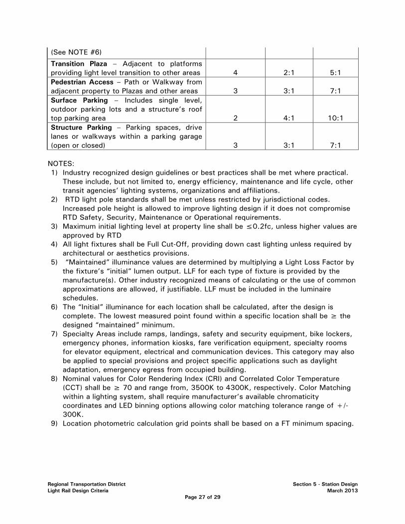
Regional Transportation District Section 5 - Station Design Light Rail Design Criteria March 2013
Page 27 of 29
(See NOTE #6)
Transition Plaza – Adjacent to platforms providing light level transition to other areas 4 2:1 5:1
Pedestrian Access – Path or Walkway from adjacent property to Plazas and other areas 3 3:1 7:1
Surface Parking – Includes single level, outdoor parking lots and a structure’s roof top parking area 2 4:1 10:1
Structure Parking – Parking spaces, drive lanes or walkways within a parking garage (open or closed) 3 3:1 7:1
NOTES: 1) Industry recognized design guidelines or best practices shall be met where practical.
These include, but not limited to, energy efficiency, maintenance and life cycle, other transit agencies’ lighting systems, organizations and affiliations.
2) RTD light pole standards shall be met unless restricted by jurisdictional codes. Increased pole height is allowed to improve lighting design if it does not compromise RTD Safety, Security, Maintenance or Operational requirements.
3) Maximum initial lighting level at property line shall be ≤0.2fc, unless higher values are approved by RTD
4) All light fixtures shall be Full Cut-Off, providing down cast lighting unless required by architectural or aesthetics provisions.
5) “Maintained” illuminance values are determined by multiplying a Light Loss Factor by the fixture’s “initial” lumen output. LLF for each type of fixture is provided by the manufacture(s). Other industry recognized means of calculating or the use of common approximations are allowed, if justifiable. LLF must be included in the luminaire schedules.
6) The “Initial” illuminance for each location shall be calculated, after the design is complete. The lowest measured point found within a specific location shall be ≥ the designed “maintained” minimum.
7) Specialty Areas include ramps, landings, safety and security equipment, bike lockers, emergency phones, information kiosks, fare verification equipment, specialty rooms for elevator equipment, electrical and communication devices. This category may also be applied to special provisions and project specific applications such as daylight adaptation, emergency egress from occupied building.
8) Nominal values for Color Rendering Index (CRI) and Correlated Color Temperature (CCT) shall be ≥ 70 and range from, 3500K to 4300K, respectively. Color Matching within a lighting system, shall require manufacturer’s available chromaticity coordinates and LED binning options allowing color matching tolerance range of +/- 300K.
9) Location photometric calculation grid points shall be based on a FT minimum spacing.
Regional Transportation District Section 5 - Station Design Light Rail Design Criteria March 2013
Page 28 of 29
5.9.8 STATION SITE LIGHTING
Station lighting includes internal site circulation and access to the station. The placement of luminaries shall not obstruct the movement of vehicles. Luminary placement shall be coordinated with the landscape and site plan to protect light standards which are located adjacent to roadways, and to ensure that plantings will not obscure the lighting distribution pattern.
5.9.9 VEHICULAR ACCESS LIGHTING
Vehicular access lighting shall provide a natural lead-in to the bus area and Kiss and Rides. The illumination on all access and egress roads shall be graduated up or down to the illumination level of the adjacent street or highway.
5.9.10 PEDESTRIAN ACCESSWAYS LIGHTING
Pedestrian accessways lighting shall define pedestrian walkways, crosswalks, ramps, stairs, tunnels and bridges.
5.9.11 PLATFORM LIGHTING
Platform area lighting shall be in any area that is used to load and unload a train. The lighting elements shall extend the entire length of the platform and shall demarcate the platform and emphasize the platform edge and vertical vehicle surfaces. Care shall be taken to avoid "blinding" LRT operators or other vehicle drivers with excessive or misdirected lighting.
5.9.12 CONTROL OF LIGHTING SYSTEMS
Lighting control shall be designed to use energy efficiently. Automatic and manual control arrangements shall ensure efficient utilization of energy and maintenance procedures. All exterior site areas shall be illuminated by a photocell with time clock or manual override.

Regional Transportation District Section 5 - Station Design Light Rail Design Criteria March 2013
Page 29 of 29
LIST OF FIGURES
FIGURE 5.1 ....... PLATFORM AT ROADWAY
FIGURE 5.2 ...... PASSENGER THROUGH ZONE
FIGURE 5.3 ....... CENTER PLATFORM
FIGURE 5.4 ....... SIDE-SIDE PLATFORM
FIGURE 5.5 ....... CENTER-SIDE PLATFORM

�����
�
��
�
AB�CDECF
��
���
��
�
���
��
AB�CDE�F
��
���
��
��A
��E��
A�B
�
���
A�
���
���
��A�
����
���
��A
���
���
��A��
��
�A
��
��
�A
��
��
���
�B
B
��
��
�
�F ���DECF��
�A
�A�
�A�
�
�
��
��
��
��
A�A�
AB��CDE!F
�B
B
��
��
�
��
���
A�
��
���
���
��
������
��E��
��
�A
��
A
�"�
��A
�
���
��
��A
�"
A�
�A
�DE�F
�!F
!#DE�F���
��B
�CDECF���
��B
�#DE�F���
��B
�CDECF���
��B
��DECF
!DE$F
!DE$F
����
��
��
����
��
��A
�
��
�A�%
�B��
��
��
���
&��A
��
���
���
A��
��
A�
�&
��
��A
�����
�A
�"A
���
AD�
����
��
��A
�"
A�
�A'
�B���
A��
BB��
���
��A
��
��
���
A����
���A�
��
���
A��
&�A
���
��A
�����
���
���
���
A��
AA�
��
��
��
���
���
A�
���
�
����
����
A�$
D����
B��
��
���
A��
��
��
��B
B��
��
���
A��
����
���
�A
��
&�
��
���
���
��
��
A��
F��
��B��A�
���
���
���
��
���
���
A�
������B
���&�A%
����������A���������A����A�����������������������������
�(C( ���)E*CCC�A�"A�+���������)C�C�
��CC����A����AA�
������������������
#B�
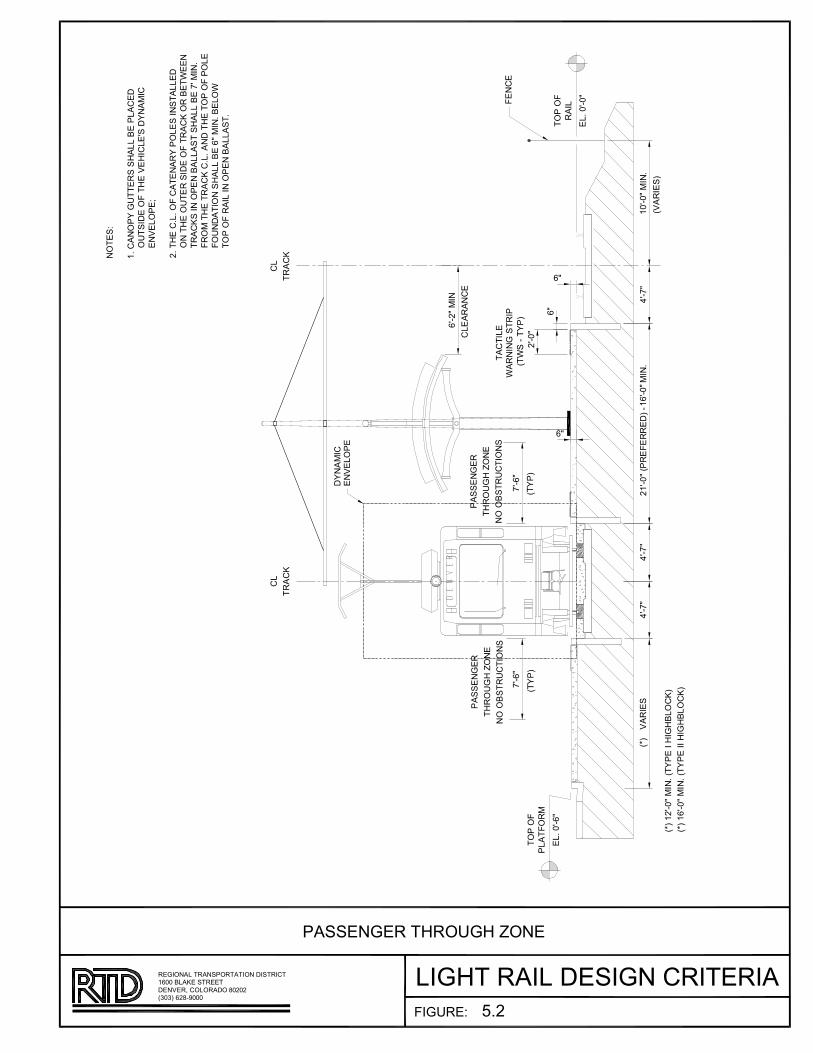
��
�����
��
�����
�������
��A�ABCD���E
CF�DC�C��E�
�����
��
��EC��
����
���C�����
F��
��EC��
E�������
���C�����
��
�����
������CFE������� �C�
��A�
�����
E�DD�AB��
�!��"B!C#�A�
A�C�$D��"����AD
E�DD�AB��
�!��"B!C#�A�
A�C�$D��"����AD
�����
%����D
F��C������C��A�CF��E�C�C!�B!$�����
F��C������C��A�CF��E�C��C!�B!$�����
��
F��E�
F��E�
�����C��A
������A��
�A����
�A%���E�
��A�
A���D&
��C��A�E�CB"����DCD!���C$�CE����
CCCC�"�D� �C��C�!�C%�!�����DC �A����
CCCC�A%���E�'
��C�!�C����C��C����A���CE���DC�AD�����
CCCC�AC�!�C�"���CD� �C��C�����C��C$����A
CCCC�����DC�AC�E�AC$����D�CD!���C$�C��C��A�
CCCC����C�!�C�����C����C�A C�!�C��EC��CE���
CCCC��"A ����ACD!���C$�C��C��A�C$���
CCCC��EC��C����C�AC�E�AC$����D��
��A��
F%����D�
�����
������
�����
������
��B"��&
��B!�C����C �D�BAC����������B��A��C���ADE�������AC �D�����
F(�(�C��)�*��� �A%��+C������ �C)����
����C$����CD�����
E�DD�AB��C�!��"B!C#�A�
,��
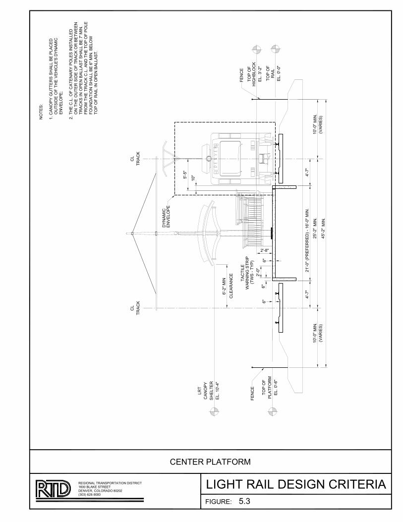
�����
����A
BCDE
FE������
����A
�EC�A�B�
FE������
�E
�BC��
�E
�BC��
�C��DEF
�CB�D����BD�
���������
�����
��
���
�����
��
������
�D��
�D��
�D��
�EFCBC��F
������D�
��������BFAFBBF ��
������
����A
!D�!"E���
FE�#����
�D��
�D��
��
EB�
�C����
�!FE�FB
FE�������
��C�D�
F�$FE��F
���%�
���F�&
���C�����'��FB��!CEE"F�EC�F
�'��D F�A�!F$F!D�EF�� ��C�D�
F�$FE��F(
���!F��E��A�C�F�CB���EF�D���CEEF
���!F�'�FB�D F�A�BC���B"F��FF�
�BC���D���F�"CEEC���!CEE"F���D��
AB���!F�BC����E�C� �!F����A��EF
A�'� C�D���!CEE"F���D��"FE��
����ABCDED���F�"CEEC���
AF��F
AF��F
�$CBDF��
�$CBDF��
������
������
������
�����
AD�'BF&
ED�!�BCDE F�D���BD�FBDCBF�D��CE�BC����B�C�D�� D��BD��
�#�#���%�)��� F�$FB*��E�BC �%����
����"EC�F��BFF�
�F��FB�EC�A�B�
��#

�����
������
ABC
�CD�EF�E�
������
�CA����
�CD�EF���
�C
�A��
�C
�A��
�F���
���F�E�
�A��BC�
�A�B�����B�
����������D�
�F�����B�
�C�AA���
������
�B���C���
�CD� F���
!F�!�
"E�
�F�E���B��
�����
�#��"�F�E���B�D�������B��B���C����
�#��"�F�E���B�D�������BB��B���C����
��
� F���
�B�D
�#�
!!F���
�F�$�
%AB��
�#�
%AB��
��F�����B�D�������B��B���C����
�����������B�D�������BB��B���C����
�F�����B�
�C�AA���
�B�D
&��A�B�
��%�C���
��
C�
�A����
���C��
�CD�"EF���
��
�F�E�
�B�D
�B�D
�����'
"D��A������(�������ACC�����CA��&
�����(��B&���������%��B�C�F��&��A�B�
������%�C���)
�D������DCD�����A���A����C���B���ACC�&
������������(����B&������A������������
�����A����B��������ACCA�����ACC�����F��
B�D
�������������A����DCD�A�&��������������C�
������(�&A�B�����ACC��������B�D���C��
�����������ABC�B��������ACCA��D
"�F�E�
�F���
�F�E�
%AB��
�B�(�'
CB����ABC�&��B����B��BA��B��AC��A�����A�B���&B��B��
� E ����$�*EEE&��%�+���C�A&��$E�E�
"�EE��CA��������
�B&�����B&���CA����
!D�

����������A��BCD�EF��
�C
��D��
�C
��D��
�D��C�
�D��������B
����������B�
�����
��
�����
�FB�FE
�DC
�C�������
�FB�FE
BCD�EF��
�C�������
C��
�D�FB�
���C���
�C�� �����
��
��������
�C�D�D���
��������
���
�!����
� ������B��E����A���
���
! ��"�
�C�D�D���
�#�� ������
������B������$CF���
�#�� ������
������B������$CF���
%D����#�
���
�����
A��D��
��%�CFB�
�F���&
���D�FB���'��������DCC�$��BCD��A
F'��A��FE�����%���C����A��D��
��%�CFB�(
���������C��FE��D���D���BFC������DCC�A
F������F'�����A��FE���D���F��$������
��D������FB���$DCCD�����DCC�$������
��
E�F��������D�����C��D�A������FB�FE�BFC�
EF'�AD�F����DCC�$���������$�CF�
�FB�FE��DC���FB���$DCCD���
E����
�%D����
�����
�����
�����
�����
E�'��&
C�����DC�A����������D���F�DC���D��BF��D�F��A�����
�)�)����*�"���A��%��+��FCF�DAF�*����
����$CD���������
����������A��BCD�EF��
!�!
Regional Transportation District Section 6-Bridges and Structures Light Rail Design Criteria March 2013
Page 1 of 23
SECTION 6 – BRIDGES & STRUCTURES
6.1 GENERAL....................................................................................................3 6.1.1 SCOPE.................................................................................................3 6.1.2 DESIGN REFERENCES............................................................................3
6.2 STRUCTURE TYPES .................................................................................... 3 6.3 DESIGN METHODS ..................................................................................... 4
6.3.1 LIGHT RAIL STRUCTURES ..................................................................... 4 6.3.2 HIGHWAY AND PEDESTRIAN STRUCTURES ............................................ 4
6.4 LOADING .................................................................................................. 4
6.4.1 DEAD LOAD ........................................................................................ 4 6.4.2 LIVE LOAD .......................................................................................... 4 6.4.3 DYNAMIC LOAD ALLOWANCE ............................................................... 6 6.4.4 DERAILMENT LOAD .............................................................................. 6 6.4.5 LONGITUDINAL FORCE ......................................................................... 7 6.4.6 CENTRIFUGAL FORCE ........................................................................... 7 6.4.7 WIND LOADS ...................................................................................... 7 6.4.8 RAIL-STRUCTURE INTERACTION (DIRECT FIXATION) ............................... 8 6.4.9 EARTHQUAKE LOADS ........................................................................ 10 6.4.10 LOAD COMBINATIONS AND LOAD FACTORS ........................................ 10
6.5 CLEARANCES .......................................................................................... 12 6.6 GEOTECHNICAL INVESTIGATIONS AND REPORTS ........................................ 12 6.7 EARTH RETAINING STRUCTURES ............................................................... 14
6.7.1 GEOMETRY ....................................................................................... 14 6.7.2 WALL TYPES ..................................................................................... 14 6.7.3 DESIGN REQUIREMENTS ..................................................................... 14 6.7.4 CHARACTERISTICS ............................................................................ 15
6.8 BRIDGES ................................................................................................. 16
6.8.1 GEOMETRY ....................................................................................... 16 6.8.2 DIRECT FIXATION .............................................................................. 17 6.8.3 INSPECTION ACCESS ......................................................................... 17 6.8.4 PROTECTION FENCING ....................................................................... 17 6.8.5 APPROACH SLABS ............................................................................. 17 6.8.6 BRIDGE DECKS .................................................................................. 18 6.8.7 DECK JOINTS .................................................................................... 18 6.8.8 PIERS AND PIER CAPS ........................................................................ 19 6.8.9 ABUTMENTS ..................................................................................... 19
Regional Transportation District Section 6-Bridges and Structures Light Rail Design Criteria March 2013
Page 2 of 23
6.8.10 BEARINGS ......................................................................................... 19 6.8.11 DRAINAGE ........................................................................................ 19 6.8.12 PIER/ABUTMENT PROTECTION ............................................................ 20
6.9 WATERPROOFING AND DAMPPROOFING .................................................... 20 6.10 STRAY CURRENT CONTROL ...................................................................... 21 6.11 TEMPORARY STRUCTURES ....................................................................... 21 6.12 OVERHEAD CONTACT SYSTEM (OCS) POLE FOUNDATIONS .......................... 21 6.13 CORROSION PROTECTION ........................................................................ 22
Regional Transportation District Section 6-Bridges and Structures Light Rail Design Criteria March 2013
Page 3 of 23
SECTION 6-BRIDGES & STRUCTURES
6.1 GENERAL
6.1.1 SCOPE
This section provides design criteria for bridges, underground structures, retaining walls, and miscellaneous structures for Light Rail projects.
Design criteria for light rail stations are included in Light Rail Design Criteria, Section 5. Design criteria for parking structures are included in Bus Transit Facility Design Criteria, Section 6.
6.1.2 DESIGN REFERENCES
Design of bridges and other structures for Light Rail conveyance shall be in accordance with: 1) AASHTO LRFD Bridge Design Specifications; 2) RTD Light Rail Design Criteria; and 3) CDOT Bridge Design Manual.
When RTD is operating partially or entirely on the ROW of either the BNSF Railway (BNSF) or the Union Pacific Railroad (UPRR), design shall also be in accordance with the BNSF/UPRR Guidelines for Railroad Grade Separation Projects.
The design and construction of freight rail bridges and associated structures shall be in accordance with: 1) AREMA Manual for Railway Engineering; 2) BNSF/UPRR Guidelines for Railroad Grade Separation Projects; and 3) CDOT Bridge Design Manual.
The design of highway bridges and associated structures shall be in accordance with: 1) AASHTO LRFD Bridge Design Specifications; 2) CDOT Bridge Design Manual; 3) BNSF/UPRR Guidelines for Railroad Grade Separation Projects, as appropriate; and 4) RTD Light Rail Design Criteria.
Pedestrian bridges shall be designed in accordance with the AASHTO LRFD Guide Specifications for the Design of Pedestrian Bridges and the CDOT Bridge Design Manual.
Where CDOT Bridge Worksheets are incorporated into the design drawings, the worksheets shall be modified for the particular application as appropriate.
Where the requirements of design references are in conflict, the provision that will result in a more conservative outcome shall apply unless otherwise approved by RTD.
6.2 STRUCTURE TYPES
Structure types and components will be restricted to those historically used by RTD or those that have been accepted for general use by other transportation authorities, and that can be demonstrated to perform well for the intent of the
Regional Transportation District Section 6-Bridges and Structures Light Rail Design Criteria March 2013
Page 4 of 23
project and under the project’s environmental conditions, including frequent freeze-thaw cycles. Experimental structure types, timber bridges, masonry bridges, and structural plate arches will not be permitted. RTD reserves the right to accept or reject the use of any structure type for any given project.
The use of lightweight concrete is not allowed for structural members.
6.3 DESIGN METHODS
6.3.1 LIGHT RAIL STRUCTURES
• Bridges – Load and Resistance Factor Design Method
• Earth Retaining Structures – Load and Resistance Factor Design Method
6.3.2 HIGHWAY AND PEDESTRIAN STRUCTURES
• Load and Resistance Factor Design Method
6.4 LOADING
Bridges and related structures shall be designed for all loads specified in the AASHTO LRFD Specifications and as modified by the appropriate RTD and railroad guidelines. Load combinations and load factors shall be as shown in Table 6.4.10-1.
6.4.1 DEAD LOAD
Track (2 rails, inside guard rails and fastenings) 200 lbs. per lineal foot
Ballast, including track ties 120 lbs. per cubic foot
Timber 60 lbs. per cubic foot
Reinforced concrete 150 lbs. per cubic foot
Earth fill materials 120 lbs. per cubic foot
Waterproofing and protective covering calculated weight
Overhead Contact System per system designer
Future Utilities 5 lbs. per square foot of deck
6.4.2 LIVE LOAD
Light Rail Vehicle (LRV) loading as shown in Figure 6.1 shall be used on dedicated ROW for RTD Light Rail trains. A train shall consist of up to four cars.
For highway and pedestrian structures, AASHTO LRFD Specifications and CDOT Bridge Design Manual live load requirements shall be used. Design of pedestrian structures shall consider the load from a maintenance vehicle. In
Regional Transportation District Section 6-Bridges and Structures Light Rail Design Criteria March 2013
Page 5 of 23
no case shall the vehicle live load be less than H-5 for bridges with a clear deck width from 6 feet up to 10 feet, and H-10 for a clear deck width 10 feet or greater. The Strength-II load combination limit state shall be used to evaluate the maintenance vehicle.
A Light Rail track shall be regarded as a traffic lane when applying the provisions of the AASHTO LRFD Specifications except as noted herein. The multiple presence factor shall be 1.0 for both one and two tracks loaded. Each track on a structure shall be loaded with LRV trains, or left unloaded, to produce the most critical force effects in the structural elements being investigated.
For evaluation of the fatigue limit state, 3 million cycles of maximum stress over the life of the structure shall be used in estimating the number of repetitive maximum stress cycles.
Deflection under LRV loads is limited to span/1000, and span/375 for cantilevers. In addition, limits are placed on the dynamic interaction between the superstructure and the LRV, by limiting the first mode natural frequency of each simple span to not less than 2.5 hertz, and not less than 3.0 hertz for one span in a series of three consecutive spans. For longer span structures that exceed these limits, a special dynamic analysis shall be conducted. The special dynamic analysis shall model the structure and transit vehicle, and shall include representation of vehicle truck spacing. To assure passenger comfort, the amplitude of the vehicle-structure dynamic response must be limited to 0.1g, where g is acceleration of gravity. The special dynamic analysis will also be used to determine whether a vertical dynamic load allowance in excess of the AASHTO LRFD requirements is warranted.
Distribution of loads for ballasted track structures: LRV axle loads may be assumed as uniformly distributed longitudinally over a length of 3 feet, plus the depth of the ballast under the tie, plus twice the effective depth of slab, except as limited by axle spacing. Wheel loads may be assumed to have lateral distribution over a width equal to the length of tie plus the depth of ballast under the tie, except as limited by the proximity of adjacent tracks or the extent of the structure.
Distribution of loads for direct fixation track structures: Where wheel loads are transmitted to the deck slab through plinths constructed on the slab, the wheel load may be assumed as uniformly distributed longitudinally over a length of 3 feet. This load may be distributed transversely (normal to the rail and centered on the rail) by the smaller of: 1) the width of the rail fastener pad plus twice the depth of the plinth concrete plus the depth of the deck; or 2) the plinth width plus the depth of the deck.

Regional Transportation District Section 6-Bridges and Structures Light Rail Design Criteria March 2013
Page 6 of 23
6.4.3 DYNAMIC LOAD ALLOWANCE
Vehicular dynamic vertical load for LRV loading shall be in accordance with AASHTO LRFD Bridge Design Specifications. In addition to the vertical dynamic load, a horizontal impact force equal to 10% of LL shall be applied. This force shall be equally distributed to the individual axles of the vehicle, and shall be applied horizontally in the vertical plane containing each axle. The force shall be assumed to act in either direction transverse to the track through a point 3 feet 6 inches above the top of the lower rail.
6.4.4 DERAILMENT LOAD
Vertical
Vertical derailment load shall be produced by up to four vehicles placed with their longitudinal axis parallel to the track and with a lateral excursion as defined in this article.
Lateral vehicle excursion at tracks not protected by guardrail shall vary from 4 inches minimum to 3 feet maximum for tangent track and curved track with radii greater than 5,000 feet. For track with radii less than 5,000 feet, the maximum excursion shall be adjusted so that the derailed wheel flange is located 8 inches from the rail traffic face of the nearest barrier, if any, or the edge of deck. For tracks protected by guardrails, the maximum excursion shall be limited by the placement of the guardrails.
A vertical impact factor of 100% of derailed axle weight shall be applied in computing the equivalent static derailment load. This derailment impact shall be applied to both axles at any single truck assembly at a time, with the AASHTO LRFD dynamic load allowance applied to all other axles. The number of vehicles and selection of axles subject to the derailment impact shall be varied in order to determine the most critical loading conditions for the structure.
When checking any component of a superstructure or substructure that supports two or more tracks, only one train on one track shall be considered to have derailed, with one other track loaded with a stationary train without impact.
All elements of the structure shall be checked assuming simultaneous application of the derailed axle loads. The reduction of positive moment in continuous spans or continuous span slabs due to derailed axle loads in adjacent spans shall not be allowed.
Horizontal
For ballasted track cross-sections having clearance between vehicle and concrete curb or barrier of 6 inches to 3 feet, with maximum vehicle speeds of 60 mph, the force due to horizontal derailment shall be taken as 40% of a
Regional Transportation District Section 6-Bridges and Structures Light Rail Design Criteria March 2013
Page 7 of 23
single LRV weight. This force shall be applied at top of curb or two feet above top of rail as appropriate, and normal to the concrete curb or barrier for a distance of 10 feet along the curb or barrier. Horizontal derailment load need not be considered where concrete curb or barrier is more than 3 feet clear from vehicles.
For direct fixation track structures, the loading and load distribution as described above shall be applied at the curb or a restraining track component. A structural element capable of withstanding the load shall be provided to limit lateral excursion towards the outside of a structure to 3 feet or less.
6.4.5 LONGITUDINAL FORCE
Provision shall be made for longitudinal force, LF, due to train acceleration and deceleration. The magnitude of LF shall be computed as follows:
A. For decelerating trains, LF shall be equal to 28% of LL without dynamic load allowance.
B. For acceleration trains, LF shall be equal to 14% of LL without dynamic load allowance.
This force shall be applied to the rails and supporting structure as a uniformly distributed load over the length of the train in a horizontal plane at the top of the low rail. Consideration shall be given to various combinations of acceleration and deceleration forces where more than one track is carried by the structure.
6.4.6 CENTRIFUGAL FORCE
Determination of centrifugal force due to the LRV on curved track shall be as provided in AASHTO specifications, without dynamic load allowance, except that the resulting force shall be applied 4 feet above the top of the lower rail of the track.
6.4.7 WIND LOADS
Wind load on structures shall conform to AASHTO Specifications.
Wind loading on the overhead contact system (OCS) shall be considered in the design of bridge superstructure and substructure elements. Loads (magnitude and location) shall be determined by the system design engineer.
For trains operating on aerial structures with the underside of the main girders not more than 40 feet (H) above the mean retarding surface, wind on live load (WL) shall consist of a transverse wind load of 115 pounds per linear foot of train and a longitudinal wind load of 28 pounds per linear foot of train. These loads shall be applied simultaneously. The transverse force shall be applied to the rails and superstructure as loads concentrated at the axle locations, and in

Regional Transportation District Section 6-Bridges and Structures Light Rail Design Criteria March 2013
Page 8 of 23
a plane 6 feet 4 inches above the top of the lower rail. The longitudinal force shall be applied to the rails and superstructure as a load uniformly distributed over the length of the train in a horizontal plane 6 feet 4 inches above the top of the lower rail.
For higher aerial structures, the value of wind on live load (WL) in the transverse and longitudinal directions shall be as follows:
H = 41 to 60 feet Transverse wind load = 126 plf Longitudinal wind load = 31 plf H = 61 to 100 feet Transverse wind load = 130 plf Longitudinal wind load = 34 plf
These loads apply to the design of the substructure elements supporting a single track. For the design of substructure elements supporting two tracks, these loads shall be increased by 30% when both tracks are loaded; this factor accounts fully for the shielding effect of vehicle-on-vehicle as two trains run alongside each other.
6.4.8 RAIL-STRUCTURE INTERACTION (DIRECT FIXATION)
Light rail bridges with direct fixation track shall be designed to accommodate the loads and displacements resulting from differential temperatures in track and structure. Structural analysis for this loading condition shall be performed using rigorous analysis methods, and shall model the rails, direct fixation rail fasteners, superstructure, substructure, and approach track. Design aids for analysis are provided in Reference (1) listed at the end of this section.
The analysis shall include evaluation for the condition of continuous rail and for the condition of one broken rail. As a minimum, the broken rail condition shall be investigated for rail break at any rail and at any abutment or other bridge expansion joint location, and at the location of maximum rail stress due to curvature for curved structures. The rail break gap shall be limited to 3 inches maximum. Temperature variations between track and structure shall include the following temperature fall and temperature rise conditions: Concrete Bridge Steel Bridge Case 1: Rail temperature fall 125 ºF 125 ºF
Bridge temperature fall 55 ºF 65 ºF Concrete Bridge Steel Bridge Case 2: Rail temperature rise 70 ºF 70 ºF
Bridge temperature rise 20 ºF 25 ºF
The preceding criteria are based on: 1) AASHTO LRFD Method B bridge temperature limits; 2) Rail setting temperature equal to 95 ºF and potential
Regional Transportation District Section 6-Bridges and Structures Light Rail Design Criteria March 2013
Page 9 of 23
reduced rail neutral temperature equal to 60 ºF; 3) Rail maximum and minimum temperatures of 130 ºF and -30 ºF, based on historical local temperature data and reported rail temperature variation from ambient temperature; 4) Bridge neutral temperature limits of 45 ºF and 85 ºF, based on Reference (2). Rail fastener properties for use in the analysis shall be:
Direct fixation fasteners Longitudinal restraint force = 3.5 kip maximum (at unbroken rail) 2.0 kip minimum (at broken rail)
Longitudinal stiffness = 21.8 kip/inch maximum (at unbroken rail) 10.2 kip/inch minimum (at broken rail)
Transverse restraint is rigid Ballasted ties (at bridge approaches)
Longitudinal restraint force = 2.4 kip Longitudinal stiffness = 15.0 kip/inch Transverse restraint force = 0.5 kip Transverse stiffness = 1.0 kip/inch
The above properties are based on manufacturer information for typical fasteners used by the RTD with allowance for long term conditions. Use of other fastener properties shall require the approval of the RTD. Fastener spacing shall be 30-inches maximum, with reduced spacing as required at curves, structure approaches, and special trackwork. The use of zero longitudinal restraint fasteners and the use of rail expansion joints are discouraged due to associated maintenance requirements, and shall require the approval of the RTD. References: (1) “Design Guideline for the Thermal Interactive Forces Between Continuously Welded Rail and the NJ Transit LRT Aerial Structures”, Parsons Brinckerhoff Quade and Douglas, July 1995. (2) “Proposed Design Method for Thermal Bridge Movements”, Charles W. Roeder, ASCE Journal of Bridge Engineering, V.8, No. 1, January 2003.

Regional Transportation District Section 6-Bridges and Structures Light Rail Design Criteria March 2013
Page 10 of 23
6.4.8.1 Bridge Deck Elevations for Direct Fixation Bridges
Bridge Deck Elevations drawings for light rail bridges with direct fixation track shall include information for superstructure deflection due to construction of plinths and rails on the composite superstructure. The “ELEV+DL” data provided in the typical tabulated deck elevations should include deflection due to all components including plinths and rails. Additional information should be provided for final rail elevations and superstructure deflection due to plinths and rails only. The additional data is used in setting plinth heights on the constructed deck. The bridge deck elevation drawings should state the loads that are included in the tabulated “ELEV+DL”, and should reference the additional deflection data for plinths and rails. For curved bridges, deflections due to plinths and rails at different girders may vary and deflection information should be provided accordingly. For curved bridges with two tracks, deflections due to plinth and rail dead load may vary significantly for loads applied at one track or the other. Plinth construction for each track will likely occur at the different times, and the designer should evaluate the significance of this effect and provide deflection data for separate track construction as appropriate.
6.4.9 EARTHQUAKE LOADS
Design of bridges for earthquake loads shall conform to AASHTO specifications. Site Class shall be provided by the project geotechnical engineer. Operational Classification of RTD LRT bridges shall be as “Other Bridges”.
6.4.10 LOAD COMBINATIONS AND LOAD FACTORS
LRFD load combinations and load factors required for design of light rail structures are specified in Table 6.4.10-1.
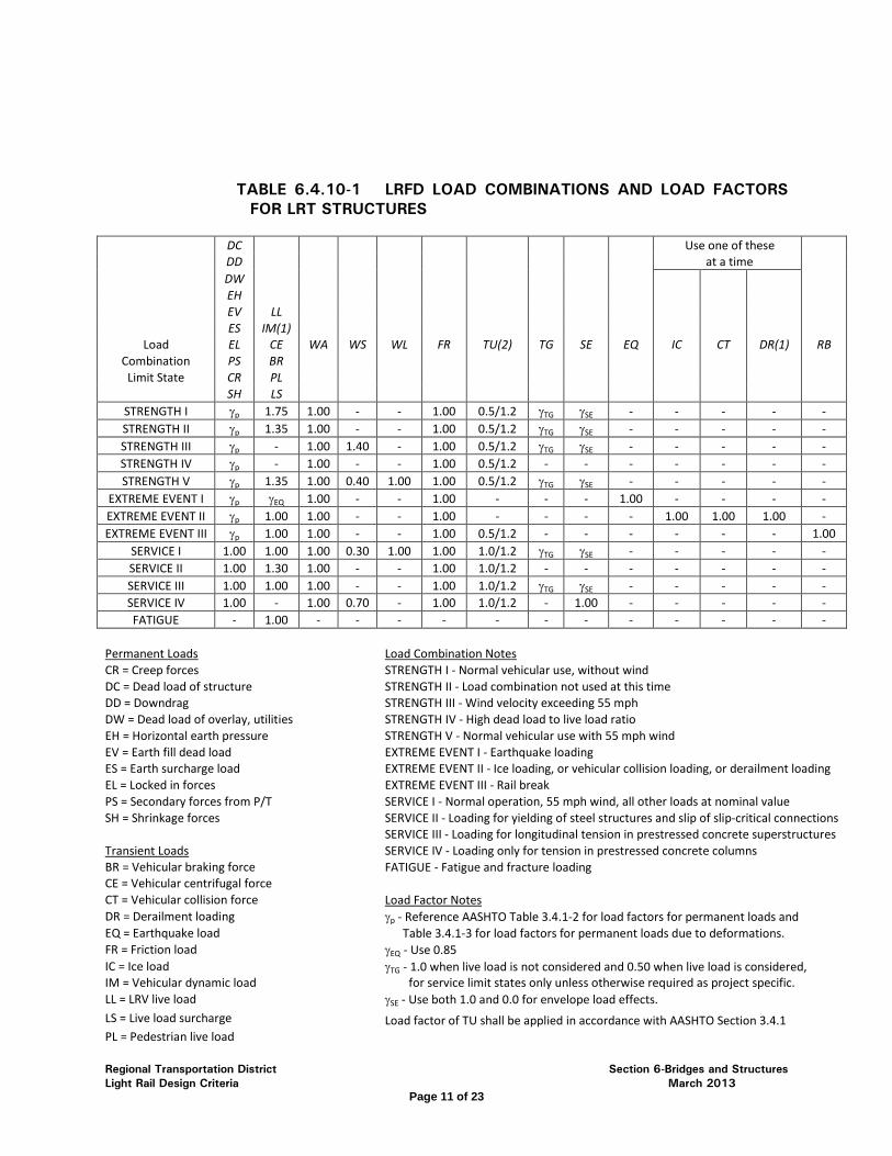
Regional Transportation District Section 6-Bridges and Structures Light Rail Design Criteria March 2013
Page 11 of 23
TABLE 6.4.10-1 LRFD LOAD COMBINATIONS AND LOAD FACTORS FOR LRT STRUCTURES
DC Use one of these DD at a time DW EH EV LL ES IM(1)
Load EL CE WA WS WL FR TU(2) TG SE EQ IC CT DR(1) RB Combination PS BR
Limit State CR PL SH LS
STRENGTH I γp 1.75 1.00 - - 1.00 0.5/1.2 γTG γSE - - - - - STRENGTH II γp 1.35 1.00 - - 1.00 0.5/1.2 γTG γSE - - - - - STRENGTH III γp - 1.00 1.40 - 1.00 0.5/1.2 γTG γSE - - - - - STRENGTH IV γp - 1.00 - - 1.00 0.5/1.2 - - - - - - - STRENGTH V γp 1.35 1.00 0.40 1.00 1.00 0.5/1.2 γTG γSE - - - - -
EXTREME EVENT I γp γEQ 1.00 - - 1.00 - - - 1.00 - - - - EXTREME EVENT II γp 1.00 1.00 - - 1.00 - - - - 1.00 1.00 1.00 - EXTREME EVENT III γp 1.00 1.00 - - 1.00 0.5/1.2 - - - - - - 1.00
SERVICE I 1.00 1.00 1.00 0.30 1.00 1.00 1.0/1.2 γTG γSE - - - - - SERVICE II 1.00 1.30 1.00 - - 1.00 1.0/1.2 - - - - - - - SERVICE III 1.00 1.00 1.00 - - 1.00 1.0/1.2 γTG γSE - - - - - SERVICE IV 1.00 - 1.00 0.70 - 1.00 1.0/1.2 - 1.00 - - - - - FATIGUE - 1.00 - - - - - - - - - - - -
Permanent Loads
Load Combination Notes CR = Creep forces
STRENGTH I - Normal vehicular use, without wind
DC = Dead load of structure
STRENGTH II - Load combination not used at this time DD = Downdrag
STRENGTH III - Wind velocity exceeding 55 mph
DW = Dead load of overlay, utilities
STRENGTH IV - High dead load to live load ratio EH = Horizontal earth pressure
STRENGTH V - Normal vehicular use with 55 mph wind
EV = Earth fill dead load
EXTREME EVENT I - Earthquake loading ES = Earth surcharge load
EXTREME EVENT II - Ice loading, or vehicular collision loading, or derailment loading
EL = Locked in forces
EXTREME EVENT III - Rail break PS = Secondary forces from P/T
SERVICE I - Normal operation, 55 mph wind, all other loads at nominal value
SH = Shrinkage forces
SERVICE II - Loading for yielding of steel structures and slip of slip-critical connections
SERVICE III - Loading for longitudinal tension in prestressed concrete superstructures
Transient Loads
SERVICE IV - Loading only for tension in prestressed concrete columns BR = Vehicular braking force
FATIGUE - Fatigue and fracture loading
CE = Vehicular centrifugal force CT = Vehicular collision force
Load Factor Notes DR = Derailment loading
γp - Reference AASHTO Table 3.4.1-2 for load factors for permanent loads and EQ = Earthquake load
Table 3.4.1-3 for load factors for permanent loads due to deformations. FR = Friction load
γEQ - Use 0.85
IC = Ice load
γTG - 1.0 when live load is not considered and 0.50 when live load is considered, IM = Vehicular dynamic load
for service limit states only unless otherwise required as project specific.
LL = LRV live load γSE - Use both 1.0 and 0.0 for envelope load effects.
LS = Live load surcharge
Load factor of TU shall be applied in accordance with AASHTO Section 3.4.1 PL = Pedestrian live load
Regional Transportation District Section 6-Bridges and Structures Light Rail Design Criteria March 2013
Page 12 of 23
RB = Rail break loading Loading Application Notes
SE = Force effect due to settlement
(1) For the Extreme Event II Load Combination, vertical impact shall be applied per TG = Force effect due to temperature gradient Light Rail Design Criteria Section 6.4.4. Normal live load impact as described TU = Force effect due to uniform temperature in Section 6.4.3 shall not be applied simultaneously with this loading. WA = Water load, stream pressure
(2) Rail structure interaction loading for direct fixation track shall be included in the
WS = Wind load on structure
uniform temperature loading, TU. WL = Wind on live load
6.5 CLEARANCES
Minimum distance between centerlines of adjacent tracks on all new construction shall be 14’-0” for main tracks. ROW limitations, bridges, tunnels, and stations may impact the track spacing and cause closer track centers. Closer track spacing shall require the approval of RTD. Other typical dimensions and clearances are shown in Section 4 and Section 9 of this Design Criteria.
Where RTD tracks are adjacent to freight rail tracks, follow the greater of clearances specified by either the railroad or by RTD. At clearance locations where superelevation is present, vertical clearances shall be measured from the high rail.
Steel superstructures within 4 feet of the electrified Overhead Contact System (OCS) envelope shall not be used. However, for existing structures or for new structures where geometric constraints render this requirement not feasible or attainable, steel superstructures within the 4-foot envelope shall be electrically insulated and protected from the power supply system, and provided with a ground electrode system. If a glastic, phenolic, or other insulating non-conductive material is used it shall be placed the entire length where the clearance is less than 4’-0” and must at a minimum extend a width of 4’-0” from the center of the OCS wire for the entire length of the non-conductive barrier. The design shall provide for ease of future maintenance and inspection when designing superstructures over the OCS envelope.
6.6 GEOTECHNICAL INVESTIGATIONS AND REPORTS
Geotechnical investigations and reports shall be provided for preliminary design and final design. Preliminary geotechnical reports should provide sufficient information to support structure type selection and preliminary level structure design. Preliminary reports should be based on site-specific information, may employ limited testing, and should include recommendations for additional exploration, testing, and other information to be included in the final geotechnical investigation when appropriate. Final reports should provide all necessary site-specific information for structure design and construction.
Frequency and depth of exploratory borings for final design shall meet the requirements of AASHTO LRFD Bridge Design Specifications, and shall consider localized subsurface irregularities. Boring frequency for preliminary design should be sufficient to provide general foundation design parameters and to identify potential problem areas. Exploratory boring plans shall be developed by the geotechnical engineer and shall be subject to the review and approval of RTD.
Regional Transportation District Section 6-Bridges and Structures Light Rail Design Criteria March 2013
Page 13 of 23
Guidelines for report content provided in this section are intended for use in combination with the geotechnical engineer’s professional judgment to provide suitable information for structure design and construction. Geotechnical reports should generally include the following where appropriate for structure type and site conditions:
• Site conditions (current and historic) • Geologic conditions • Subsurface conditions • Surficial geology • Plan location of borings • Bore logs with depth and geologic stratigraphy • Previous borings information • Legends and notes of exploratory borings • Groundwater potential, depth and possible fluctuations • Summary of laboratory test results • Soil corrosive potential test results • Sulfide content • Swell compression test results • Gradation test results • Liquid and Plastic Limits (LL and PL) • Plasticity Index Pl) • Moisture density relationships (dry density and optimum moisture content) • AASHTO T-99, T-180 (modified and standard proctor applications) • Dewatering requirements and recommendations • Monitoring requirements and recommendations • Potential utility conflicts
• Structure foundation recommendations • Retaining wall recommendations • Foundation vertical capacity criteria • Foundation lateral capacity parameters • Lateral earth pressures • Subgrade improvement requirements for shallow foundations • Swelling soils mitigation recommendations • Soil sampling and analysis for scour analysis per Section 3.5.4.3, Bridges
over Drainageways • Seismic site class and design parameters • Soil corrosion assessment and mitigation measures • Soil sulfate evaluation and cement type recommendation
• Other items as determined for specific site conditions

Regional Transportation District Section 6-Bridges and Structures Light Rail Design Criteria March 2013
Page 14 of 23
6.7 EARTH RETAINING STRUCTURES
6.7.1 GEOMETRY
Retaining wall layout shall address slope maintenance above and below the wall. Provide returns into the retained fill or cut at retaining wall ends where possible. Any residual wall batter should be into the fill. Design and construction shall consider surface and subsurface drainage. A drainage system shall be provided to intercept or prevent surface water from entering behind walls. A fence or protection railing with a minimum height of 3 feet 6 inches above a standing surface shall be provided at the top of walls 2 feet 6 inches or higher. (Reference RTD Light Rail Criteria Section 14.7.0 for additional fencing requirements.)
6.7.2 WALL TYPES
Metal walls, including bin walls and sheet pile walls, recycled material walls, and timber walls will not be permitted for permanent retaining walls. The proposed wall types shall have been successfully used for similar loading, geotechnical, and environmental conditions.
The use of Mechanically Stabilized Earth (MSE) walls to support freight rail loadings must be approved by the controlling railroad.
6.7.3 DESIGN REQUIREMENTS
Retaining walls shall be designed in accordance with the applicable standards and references outlined in this Design Criteria. Lateral earth pressures used in design shall be consistent with backfill type shown on the plans, the geotechnical report, and the requirements of Section 206 of the CDOT Standard Specifications for Road and Bridge Construction. Appropriate drainage details shall be provided for all retaining walls. Retaining walls shall be designed and constructed to have a minimum service life of 75 years.
The design of MSE and modular walls near or in bodies of water shall account for soft saturated soils and scour, and shall be coordinated with project geotechnical and drainage engineering disciplines.
Retaining walls near irrigation lines for landscaping shall account for the additional hydrostatic load due to a waterline break. Free draining backfill material and/or leak detection devices shall be provided to reduce hydrostatic loads on these walls.
LRV load surcharge on retaining walls shall be determined by treating the vehicle axles or wheels as point, line, or strip loads, rather than an equivalent height of soil. The horizontal pressure distributions given in AASHTO LRFD may be used, and axle or wheel loads may be distributed according to this Design Criteria, for ballasted or direct fixation track as appropriate.

Regional Transportation District Section 6-Bridges and Structures Light Rail Design Criteria March 2013
Page 15 of 23
6.7.4 CHARACTERISTICS
Mechanically Stabilized Earth (MSE) Walls
Concrete panel facing shall be used at MSE walls subject to any of the following conditions: 1) Walls that support elevated track or roadway; 2) Walls at depressed track and that retain a fill height greater than 6 feet including height of sloping surcharge; 3) Walls at secondary locations that retain a fill height greater than 15 feet including sloping backfill height.
MSE walls with concrete block facing, and modular walls with or without soil reinforcement, may be used under conditions that do not include the preceding.
Wall panels shall be constructed of reinforced concrete. Provide corrosion protection for prestressing or post-tensioning steel. Cover to reinforcing steel shall be a minimum of 2 inches. All reinforcing, mild or prestressed, shall be galvanized or epoxy coated in splash zones of adjacent roadways. Panel joints shall accommodate differential settlement.
Mechanical connection of soil reinforcement to the wall facing for soil reinforcement shall be provided; friction connections relying on gravity alone will not be acceptable.
Soil reinforcement for MSE and modular walls shall be galvanized, epoxy coated steel, or geogrid meeting the creep requirements of AASHTO Specifications. Design shall account for any item projecting through the soil reinforcement. Avoid placing culverts and utilities perpendicular to soil reinforcement within the reinforced soil mass. Soil reinforcement shall be protected from corrosion of metal due to stray electrical currents. Stray current control shall follow the requirements of RTD Light Rail Design Criteria, Section 10, Stray Current Control.
Where the use of MSE walls is proposed on electric traction systems utilizing direct current, an Engineer specializing in corrosion protection/prevention shall investigate and make site-specific recommendations for special design considerations.
Consideration shall be given to the potential for accelerated corrosion or deterioration of structural elements of MSE walls due to the relatively high permeability of railroad roadbeds and the potential for precipitation and other potentially corrosive substances infiltrating the roadbed. Impermeable geomembrane connected to lateral drains below the sub-ballast and above the top level of reinforcements should be provided unless omission can be justified.
Consideration in design shall be given to placing soil reinforcements around intrusions such as catenary pole foundations, abutment caissons and piling,
Regional Transportation District Section 6-Bridges and Structures Light Rail Design Criteria March 2013
Page 16 of 23
and vaults. Soil reinforcements shall be placed to protect the structural integrity of the MSE walls.
Consideration should be given to placing the uppermost level of reinforcing elements below the depth of excavation that would be reached in the placement of utilities within the ROW. Alternately, conduits for utilities should be placed during the MSE construction.
Excavation to, or below, the top level of reinforcing elements shall not be allowed following the construction of the MSE.
Cast-in-Place Walls - Cast in place walls shall be designed and constructed in accordance with the current AASHTO LRFD specifications and the CDOT Bridge Design Manual and standards. Expansion joints and weakened planes shall be provided as necessary to accommodate differential movements.
Anchored Walls - Anchored wall design and construction shall use FHWA RD-82-046, FHWA RD-82-047 and FHWA-IF-99-015 as guidelines. Anchors shall be encapsulated with plastic sheathing. Proof load tests for anchors shall be provided in accordance with the above FHWA guidelines. Shotcrete shall meet the aesthetic requirements set by RTD.
Soil Nail Walls - Soil nail walls may be used when top-down construction is warranted. Soil nail walls shall not be used if ground water seepage will be a problem. Design and construction shall use FHWA-RD-89-93, FHWA-SA-93-086 and FHWA-SA-96-069 as guidelines. Load testing of soil nails shall be provided in accordance with the above FHWA guidelines. Shotcrete shall meet the aesthetic requirements, including final finish, as established by RTD.
Structural Diaphragm and Caisson Walls - Structural diaphragm walls and caisson walls may be used when top-down construction is warranted.
6.8 BRIDGES
6.8.1 GEOMETRY
All fill and cut slopes along the longitudinal axis of bridges with spill through abutments shall not be steeper than 2:1 perpendicular to the face of each abutment. There shall be a 2-foot berm at the top of slopes in front of abutments. Along the LRT alignment, where the tracks are depressed or elevated on a structure, a 2 foot 6 inch emergency/maintenance walkway shall be provided for each track. Bridge supports shall be oriented radially for curved structures where practical. The maximum bridge skew shall be 30˚ away from radial supports (or a line normal to the LRT alignment for tangent track), if practical.

Regional Transportation District Section 6-Bridges and Structures Light Rail Design Criteria March 2013
Page 17 of 23
To avoid excessive longitudinal forces, continuous welded rail shall not be terminated on structures.
6.8.2 DIRECT FIXATION
Direct fixation track may be proposed for use on Light Rail bridges where superstructure depth limitation is beneficial for track alignment and construction economy, subject to the approval of RTD. Underground structures longer than 400 feet shall use direct fixation, unless otherwise approved by RTD.
6.8.3 INSPECTION ACCESS
All bridge superstructures, joints and bearings (Type II or Type III) shall be made accessible for long-term inspection. Superstructures consisting of I-girders with exposed cross frames shall be made accessible with walkways, ladders, or by use of a snooper truck. Steel box girders, cast-in-place concrete box girders and precast prestressed concrete “U” girders with an inside depth of 5 feet or more shall be made accessible for interior inspection. Bottom slab access doors shall be placed at locations which do not impact traffic under the bridge and shall swing into the box girder. Box girders shall be protected from access by vermin.
During construction, wooden formwork shall be removed from the interiors of box or “U” girders that are made accessible for interior inspection.
6.8.4 PROTECTION FENCING
LRT bridges shall have a protection fence adjacent to the emergency/maintenance walkway with a minimum height of 3 feet 6 inches above the walkway surface. Walls greater than 2 feet 6 inches high above the adjacent surface outside of the LRT envelope shall have protection fence or barrier with a minimum height 3 feet 6 inches above the trackway or walkway surface. Chain link mesh shall be vinyl-coated, and shall have 3/8 inch mesh opening at locations adjacent to highways or where snow and ice may be thrown from snow removal equipment onto patrons. (Reference RTD Light Rail Criteria Section 14.7.0 for additional fencing requirements.)
6.8.5 APPROACH SLABS
Special considerations for transition areas and treatment at slab ends shall be in accordance with AREMA Manual Chapter 8, Section 27.8.
Approach slabs shall be provided at each end of LRT bridges. The approach slab shall be a minimum of 25 feet in length measured along the centerline of the bridge. The end of the approach slab shall be perpendicular to the track centerline if at all possible. The approach slab shall be 2 feet wider than the track tie length at a minimum. The approach slab may be the same width as
Regional Transportation District Section 6-Bridges and Structures Light Rail Design Criteria March 2013
Page 18 of 23
the bridge deck (minus the width of the protection fence or curb) and provide for the smooth transition from ballasted section to bridge structures. Track tie spacing shall be reduced from 30 inches to 21 inches on approach slabs.
An underdrain system shall be provided beneath all approach slabs to reduce water infiltration into embankment fills at bridge abutments. Bridge deck drains shall be located to minimize the amount of water flowing across all joints.
Differential settlement across approach slabs shall be less than 1 inch. Ground improvement design for stabilization of the approach embankment subgrade shall be provided by the project geotechnical engineer as needed to meet this requirement.
6.8.6 BRIDGE DECKS
Provide a minimum deck thickness of 8 inches. Open or filled grating decks and orthotropic decks will not be permitted. Use of permanent deck forms shall follow CDOT Bridge Design Manual guidelines. Pretensioned, precast concrete deck forms shall be a minimum of 3.5 inches thick and have a full grout or concrete bearing. Width of bearing support for precast deck forms shall be based on design loading and shall be shown on the drawings. Precast deck forms shall not be used for bridges with direct fixation track due to plinth-slab dowel reinforcement development length requirements. Parallel bridges shall have a minimum 1 inch (4 inch preferred) longitudinal gap between decks or parapets, or shall be tied together to make one structure. Ballasted track bridges shall be protected with an appropriate waterproofing.
The use of epoxy coated reinforcing steel for all bridges, walls, tunnels and box culverts shall adhere to the requirements of the CDOT Bridge Design Manual. The design category for anticipated level of de-icing salt application shall be “Low”. The protection of reinforcing steel for LRT bridges shall follow the requirements for stray current/corrosion control provided in the RTD Light Rail Design Criteria.
Bridge deck and approach slab surface smoothness on direct fixation bridges shall not deviate more than 3/8 inch in 25 feet using a profilograph as described in Subsection 412.17(a) of the CDOT Standard Specifications for Road and Bridge Construction. The profile index shall start and terminate on the bridge approach slab. One profile shall be taken for each track lane.
6.8.7 DECK JOINTS
The number of deck joints shall be minimized. All expansion joints shall be a CDOT-approved strip seal or modular joint. Design and location of joints shall provide for maintenance accessibility and future replacement. Modular joints shall be designed and tested for fatigue loading.
Regional Transportation District Section 6-Bridges and Structures Light Rail Design Criteria March 2013
Page 19 of 23
6.8.8 PIERS AND PIER CAPS
Pier caps and columns shall preferably be architecturally consistent within a corridor, and with the bridge superstructure. Drop caps or integral caps are acceptable. Integral caps are preferred with cast-in-place concrete box girder systems. The use of integral steel pier caps is not preferred, but if used, the caps shall be filled with concrete and post-tensioned. Integral pier caps at box girder bridges shall provide inspection access in accordance with CDOT Bridge Design Manual requirements for pier diaphragms.
6.8.9 ABUTMENTS
Abutments shall preferably be integral, end diaphragm-type where practical. Retaining walls may be used in lieu of wing walls at abutments. Slope protection shall be provided at slopes under bridges, conforming to the details contained in the CDOT Standard Structural Worksheets, Slope Paving Details.
Tall abutments may be MSE abutments with deep foundations, or full height concrete U-abutments with multiple row pile or caisson foundations. MSE abutments should be avoided at skewed bridges with acute corners between abutment and wing walls. Design and detailing of MSE abutments shall prevent or fully account for transfer of horizontal loads from the bridge to MSE wall. MSE abutment walls shall be designed and specified as using inextensible soil reinforcement. Bridges with full height concrete abutments should use an end diaphragm integral with the superstructure instead of an abutment back wall with expansion joint between deck and back wall. Reinforced earth backfill should be provided behind the end diaphragm, with void form between backfill and end diaphragm sufficient to allow bridge expansion movement.
6.8.10 BEARINGS
Bearing design and related structure details shall provide accessibility for maintenance and future bearing replacement. Superstructure and substructure design and details shall provide jacking points, and shall provide sufficient access to allow bearing removal. Elastomeric bearings are preferred. Sole plates shall be 1.25 inch minimum thickness for Type I bearings, and 1.5 inch minimum thickness for Type II bearings. Type II expansion bearings shall include the use of a positive stop to prevent elastomeric pad walking at the bearing seat. Provide at least 3 inches of cover between anchor bolts and the edge of the concrete pedestals. Provide reinforcement for pedestals greater than 3 inches high.
6.8.11 DRAINAGE
Bridge deck drainage shall conform to the requirements of Section 3.5.4.2 of this manual.
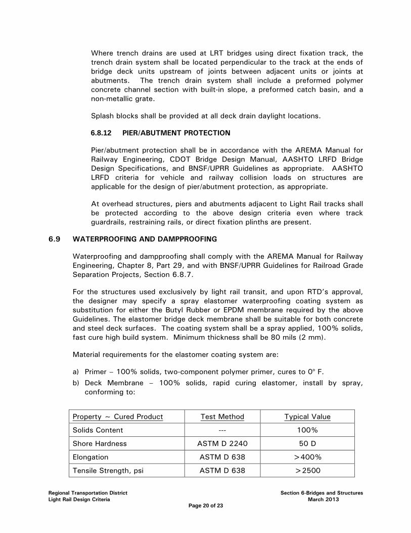
Regional Transportation District Section 6-Bridges and Structures Light Rail Design Criteria March 2013
Page 20 of 23
Where trench drains are used at LRT bridges using direct fixation track, the trench drain system shall be located perpendicular to the track at the ends of bridge deck units upstream of joints between adjacent units or joints at abutments. The trench drain system shall include a preformed polymer concrete channel section with built-in slope, a preformed catch basin, and a non-metallic grate.
Splash blocks shall be provided at all deck drain daylight locations.
6.8.12 PIER/ABUTMENT PROTECTION
Pier/abutment protection shall be in accordance with the AREMA Manual for Railway Engineering, CDOT Bridge Design Manual, AASHTO LRFD Bridge Design Specifications, and BNSF/UPRR Guidelines as appropriate. AASHTO LRFD criteria for vehicle and railway collision loads on structures are applicable for the design of pier/abutment protection, as appropriate.
At overhead structures, piers and abutments adjacent to Light Rail tracks shall be protected according to the above design criteria even where track guardrails, restraining rails, or direct fixation plinths are present.
6.9 WATERPROOFING AND DAMPPROOFING
Waterproofing and dampproofing shall comply with the AREMA Manual for Railway Engineering, Chapter 8, Part 29, and with BNSF/UPRR Guidelines for Railroad Grade Separation Projects, Section 6.8.7.
For the structures used exclusively by light rail transit, and upon RTD’s approval, the designer may specify a spray elastomer waterproofing coating system as substitution for either the Butyl Rubber or EPDM membrane required by the above Guidelines. The elastomer bridge deck membrane shall be suitable for both concrete and steel deck surfaces. The coating system shall be a spray applied, 100% solids, fast cure high build system. Minimum thickness shall be 80 mils (2 mm).
Material requirements for the elastomer coating system are:
a) Primer – 100% solids, two-component polymer primer, cures to 0o F. b) Deck Membrane – 100% solids, rapid curing elastomer, install by spray,
conforming to:
Property ~ Cured Product Test Method Typical Value
Solids Content --- 100%
Shore Hardness ASTM D 2240 50 D
Elongation ASTM D 638 >400%
Tensile Strength, psi ASTM D 638 >2500

Regional Transportation District Section 6-Bridges and Structures Light Rail Design Criteria March 2013
Page 21 of 23
Tear Strength, pounds force/inch, Die C
ASTM D 624 390
Taber Abrasion, mg. Loss (1000 gm, 1000 rev, H-18)
ASTM D 4060 250
Moisture Vapor Transmission
ASTM E 96 <0.025 perms
Gel Time --- <10 Seconds
Tack Free --- <30 Seconds
Open to Light Traffic --- 1 Hour
Electrical Resistance ASTM D257 2.0 by 1013 ohm-cm
Ballast Test Min. 2,000,000 cycles no damage. Performed with No. 4 bridge ballast to a depth of 8
inches.
The use of protective asphaltic panels is not required with the elastomer bridge deck membrane. However, a film thickness test is required before the deck membrane is accepted.
6.10 STRAY CURRENT CONTROL
Stray current control shall comply with the requirements of the Light Rail Design Criteria, Section 10, Stray Current/Corrosion Control. Requirements for buried concrete/reinforced concrete structures are provided in Section 10.2.6.5. Requirements for aerial structures are provided in Section 10.3.2.1.
6.11 TEMPORARY STRUCTURES
Temporary structures including falsework, and shoring systems consisting of cantilevered sheet piling, anchored sheet piles, cantilevered and anchored soldier beams with lagging, braced excavation, and cofferdams shall be designed and constructed in accordance with CDOT requirements (including vehicular collision), AREMA Chapter 8, and as modified by the appropriate Railroad Guidelines.
6.12 OVERHEAD CONTACT SYSTEM (OCS) POLE FOUNDATIONS
Foundations for OCS poles shall be either cast-in-place or precast reinforced concrete. The design of foundations for supporting structures and guy anchors shall be based on the structure loading calculations and soil data. The supporting structure foundations shall be designed to accept anchor bolts and base plates and shall have provision for feeder conduits and structure grounding.

Regional Transportation District Section 6-Bridges and Structures Light Rail Design Criteria March 2013
Page 22 of 23
6.13 CORROSION PROTECTION
Structural steel at pedestrian areas where deicing salts will potentially be used shall be hot-dip galvanized in accordance with ASTM A123. Structural steel subject to these provisions includes, but is not limited to: structural framing, handrails and railing systems, light poles, sign poles, base plates, and components embedded in concrete. All hardware used at galvanized structural steel, including anchor rods, bolts, nuts, and washers, shall be hot-dip galvanized in accordance with ASTM A153. Attention shall be provided in design and detailing to preclude conditions that trap water and/or deicing chemicals. Tube members should be provided with weep holes to drain condensation from atmospheric moisture. Concrete foundation piers supporting post base plates should be raised above the surrounding grade where practical. Railing base plates that bear on a concrete slab should be sealed around the plate perimeter. Where hot-dip galvanized steel is to be painted, galvanized surfaces shall be prepared in accordance with ASTM D6386-10. Paint systems for galvanized surfaces should include an epoxy primer and a corrosion resistant top coat.

Regional Transportation District Section 6-Bridges and Structures Light Rail Design Criteria March 2013
Page 23 of 23
LIST OF FIGURES
6-1 LRV Loading Diagram
6-2 Typical Depressed Section with One Adjacent Wall – Tangent Track
6-3 Typical Retaining Wall Approach – Tangent Track
6-4 Tunnel Section – Tangent Track (Long Tunnel >400’)
6-5 Ballasted Deck Bridge – Tangent Track
6-6 Direct Fixation Deck Bridge – Tangent Track
6-7 Ballasted Deck Dual Track Bridge – Tangent Track
6-8 Direct Fixation Deck Dual Track Bridge – Tangent Track
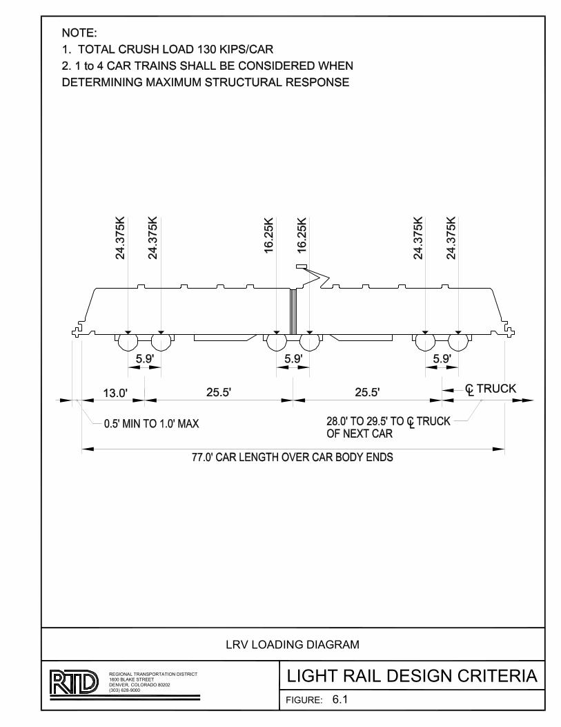
FIGURE:
LIGHT RAIL DESIGN CRITERIAREGIONAL TRANSPORTATION DISTRICT
(303) 628�9000DENVER, COLORADO 80202
1600 BLAKE STREET
LRV LOADING DIAGRAM
6.1
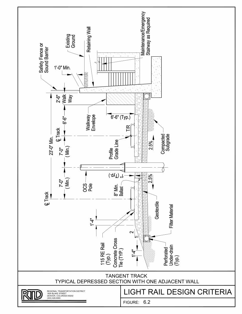
��������A�BACCA�CA���DE�F����DEA�����AE��F���
����BA�
������B����AC��E��B��AB��BA��DE����B�EC�DB����DE��C�B���
��������������AE�AB ��D�DB�D������
!����"��#A�C�BAA�
��E�AE���B��#
�$�
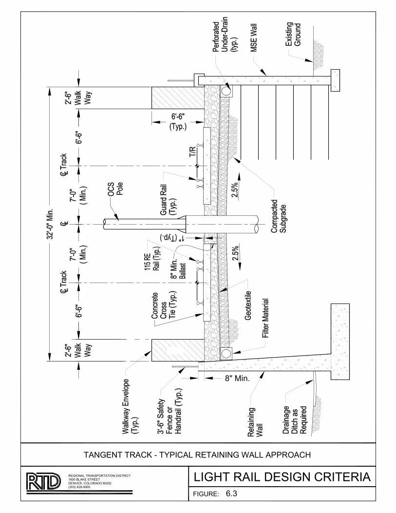
�������
���AB�C��BD�E��FB���A���C�����FC�BA�CFE���ACA��FBD�EA���A
�����B��������D�F����B�����CD�B�����
����B��C �BEA���A
ACF��FABA�C� B�BA!���C�B��AC�F�F�B"C��BC����C�
�#�
�$B%&'#

���������AB
CDAEF���D���D��
�A�F��������
���EE��EF�D�������A�����E�D� E��!
"D E�#D��#
��"����#$�����E�AE�DAE E��#�
�%&'()*
+%&,��(-%+�C)�%&.��(%�)(%-()&%�.-+��(-.�/�(�-�%�.�C%��(%��
�010��2345�111C).6)(!���+�(-C��41313
7211�8+-9)���())�
�-.&).���(-�9�5��'..)+��)��%�.�5�+�.&��'..)+
2�:
2;�<D��

�������
���AB�C��BD�E��FB���A���C�����FC�BA�CFE���ACA��FBD�EA���A
�����B��������D�F����B�����CD�B�����
����B��C �BEA���A
ACF��FABA�C� B�B�C��CEA�DBD�� B���D��
�!"
�#$%&'
��(B)%*!
�#++#',
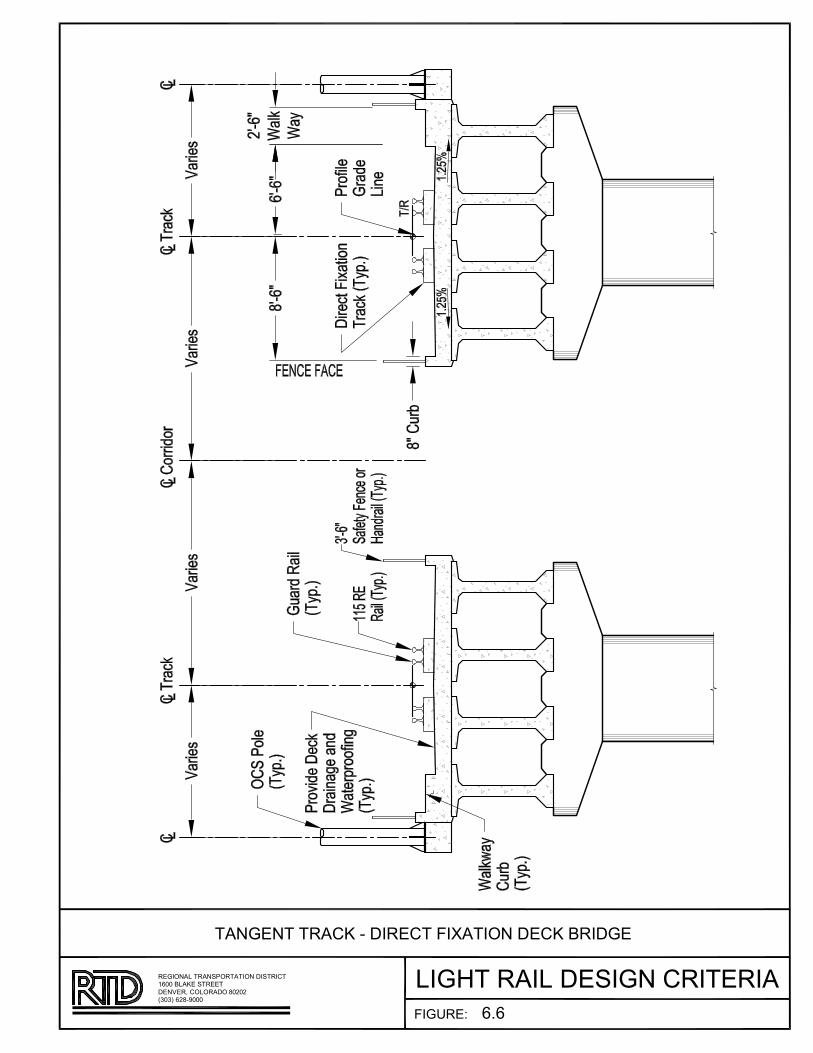
�������
���AB�C��BD�E��FB���A���C�����FC�BA�CFE���ACA��FBD�EA���A
�����B��������D�F����B�����CD�B�����
����B��C �BEA���A
ACF��FABA�C� B�BD����AB��!CA��FBD�� B���D��
�"�

�������
���AB�C��BD�E��FB���A���C�����FC�BA�CFE���ACA��FBD�EA���A
�����B��������D�F����B�����CD�B�����
����B��C �BEA���A
ACF��FABA�C� EB�B�C��CEA�DBD�� BD�C�BA�C� B���D��
�!"
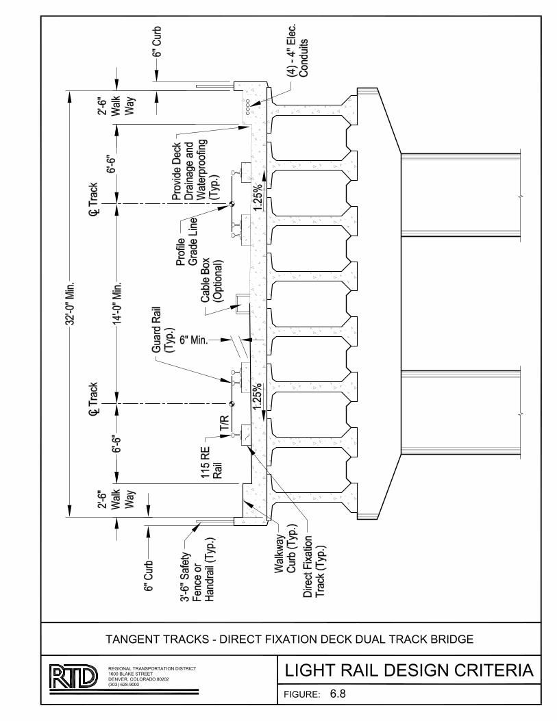
�������
���AB�C��BD�E��FB���A���C�����FC�BA�CFE���ACA��FBD�EA���A
�����B��������D�F����B�����CD�B�����
����B��C �BEA���A
ACF��FABA�C� EB�BD����AB��!CA��FBD�� BD�C�BA�C� B���D��
�"�

Regional Transportation District Section 7 - Communications and Central Control Light Rail Design Criteria March 2013
Page 1 of 15
SECTION 7 - COMMUNICATIONS AND CENTRAL CONTROL 7.1 GENERAL .................................................................................................... 2 7.2 STANDARDS AND CODES............................................................................. 3 7.3 OPERATIONS CONTROL CENTER (OCC) .......................................................... 3
7.3.1 CONTROL ROOM LAYOUT .............................................................. 3 7.3.2 CONSOLES ................................................................................... 3 7.3.3 ENVIRONMENTAL CONSIDERATIONS ............................................... 4
7.4 SCADA ....................................................................................................... 5
7.4.1 SAFETY CONSTRAINTS ON SCADA ................................................. 5 7.4.2 SYSTEM OPERATION ..................................................................... 5 7.4.3 SYSTEM REQUIREMENTS ............................................................... 6 7.4.4 DISPLAYS ..................................................................................... 6 7.4.5 SOFTWARE ................................................................................... 7 7.4.6 CENTRAL EQUIPMENT ................................................................... 8 7.4.7 REMOTE I/O EQUIPMENT ................................................................ 9
7.5 COMMUNICATIONS ................................................................................... 10
7.5.1 RADIO SYSTEM ........................................................................... 10 7.5.2 TELEPHONE SYSTEM ................................................................... 10 7.5.3 CCTV SYSTEM ............................................................................ 11 7.5.4 PA/VMS SYSTEM ........................................................................ 11 7.5.5 COMMUNICATION TRANSMISSION SYSTEM .................................. 12 7.5.6 NETWORK MANAGEMENT SYSTEM ............................................... 12 7.5.7 COMMUNICATION HOUSES AND ENCLOSURES .............................. 12 7.5.8 COMMUNICATION POWER SYSTEM .............................................. 13 7.5.9 LOCATION OF COMMUNICATION ENCLOSURES AND EQUIPMENT .... 13
7.6 INTERFACE REQUIREMENTS ........................................................................ 14
7.6.1 CENTRAL CONTROL FACILITY ...................................................... 14 7.6.2 SCADA REMOTE I/O EQUIPMENT .................................................. 14 7.6.3 ELECTROMAGNETIC COMPATIBILITY REQUIREMENTS...................15
Regional Transportation District Section 7 - Communications and Central Control Light Rail Design Criteria March 2013
Page 2 of 15
SECTION 7 - COMMUNICATIONS AND CENTRAL CONTROL
7.1 GENERAL
The Communications and Central Control System (CCS) includes communications equipment, the remote I/O equipment, and the human interface equipment to help allow controllers to monitor wayside systems and facilities and supervise mainline rail operation.
Designer shall review past communications systems designs in order to understand and use past design principles to maintain consistency in designs.
The CCS and Supervisory Control and Data Acquisition (SCADA) System shall be provided on the entire LRT system. The scope includes:
• A CCS with supervisory control to allow RTD Operations personnel to remotely monitor the signal system, traction electrification system, ticket vending machines, and station and wayside facilities, issue route requests to the signal system and issue commands to open and close breakers to the traction electrification system.
• Remote I/O equipment interconnecting RTD's OCC with signal cases and houses, communications equipment houses and cabinets, and traction power substations.
• Radio control equipment to be used at the control room.
• Telephone switches and telephones for voice communication from the control room to other RTD personnel and to outside personnel.
• Emergency telephones installed in elevators, LRT tunnels, on platforms and other passenger waiting areas.
• A closed circuit television (CCTV) system to allow RTD personnel at the control room and in the Security Command Center to monitor activity at parking facilities, elevators and station platforms. Refer to Section 14 - System Safety and System Security.
• A public address/variable message sign system (PA/VMS) and interface equipment, accessible from the control room and at designated passenger stations to enable audible and visual text display of passenger information.
• A communications transmission system (CTS) consisting of hardware, and copper and fiber optic cable to carry RTD voice, data, and video communication information. The Design Engineer shall coordinate fiber optic specifications with RTD’s SCADA Communications Engineer.
• Communication houses, cabinets, batteries, chargers, raceway, etc. to enable reliable operation of wayside communications equipment.
• Modification of LRT Communications System shall support Light Rail operation on the existing and all planned corridors. The LRT Communications System shall be able to grow to support growth of RTD’s LRT System while the RTD light rail system continues to operate with the LRT Communications System. Growth to the RTD Light Rail System size shall be able to be achieved in a manner meeting all of the following requirements:
o By adding equipment

Regional Transportation District Section 7 - Communications and Central Control Light Rail Design Criteria March 2013
Page 3 of 15
o By modifying software licenses to accommodate the increase elements o Without the need to replace or remove equipment provided under this
Contract (and without loss of use of that equipment) o Without software code changes
7.2 STANDARDS AND CODES
The communications and central control system shall be designed and implemented to the latest revision at the time of award of contract of the applicable codes and standards of the following organizations:
• American National Standards Institute (ANSI)
• Electronic Industries Association (EIA)
• Federal Communication Commission (FCC)
• Institute of Electrical and Electronics Engineers (IEEE)
• International Organization for Standardization (ISO)
• National Electrical Manufacturers Association (NEMA)
• National Fire Protection Association (NFPA)
• Building Industry Consulting Standards Institute (BICSI)
• Internet Engineering Task Force (IETF)
7.3 OPERATIONS CONTROL CENTER (OCC)
The OCC shall be designed to be a comfortable, quiet, ergonomic and uncluttered working area that meets the requirements of the Americans with Disabilities Act Accessibility Guidelines for Buildings and Facilities (ADAAG).
7.3.1 CONTROL ROOM LAYOUT
The layout of the control room shall be such that the control room staff can work and interact with each other effectively and efficiently. To be most effective, the staff positions within the control room shall be within line-of-sight of one another to allow the use of visual signals to supplement their voices.
Access to the control room shall be located to minimize the disturbance to staff communications or their view of the overview display.
7.3.2 CONSOLES
Control room staff shall utilize consoles to supervise LRT system activities. Each console within the control room shall contain the communications, reporting, controls, and monitoring equipment necessary to carry out the assigned functions by the controllers. All controller consoles shall be identical.
All consoles shall have the following design requirements:
Regional Transportation District Section 7 - Communications and Central Control Light Rail Design Criteria March 2013
Page 4 of 15
• Like equipment and procedures shall be used for like functions and like functions shall be in the same general physical location in each console.
• Frequently used equipment shall be located most conveniently. Most frequently used procedures shall require the fewest, least extended motions possible.
• The amount of equipment and variety of procedures at a console shall be minimized, consistent with requirements for modular and expandable design.
• Voice communication interfaces shall be integrated such that OCC staff need not switch between more than two devices to interact with the several parties with whom they may need to maintain contact. Audio outputs shall have volume and tone controls.
• Console physical dimensions shall be consistent with ergonomic limits. Consoles shall be designed to accommodate the reach of a 5th percentile female and the size of a 95th percentile male.
• Console components shall be modular to allow replacement of a failed unit within 30 minutes, and replacement shall not require shutdown of the functioning portion of the console.
• Writing and documentation storage space shall be provided. The controller consoles shall have the following design requirements.
A keyboard and point-and-click device shall be able to be used for display item selection and function initiation. Single purpose function buttons and switches may be used for, but limited to, functions which are frequently used or require rapid activation.
Console display monitors shall be high definition, with a minimum resolution or 1080p, low flicker. Color capabilities shall be consistent with information requirements. Console monitors shall be selected and placed to minimize emission exposure. Monitors shall have easily accessible intensity and color controls.
Console furniture and chairs shall be consistent with ANSI/HFS 100, “American National Standard for Human Factors Engineering of Visual Display Terminal Workstations".
Controller consoles shall be assignable to a geographic portion of the LRT system.
7.3.3 ENVIRONMENTAL CONSIDERATIONS
The following site requirements shall apply at the OCC:
• The OCC shall meet all applicable fire safety requirements, including NFPA 130. A fire alarm and suppression system shall be provided for the control room and equipment room.
Regional Transportation District Section 7 - Communications and Central Control Light Rail Design Criteria March 2013
Page 5 of 15
• Raised flooring with removable tiles shall be provided for the control room and equipment room. The metallic floor framing shall be grounded.
• Wide door access shall be provided at the control room and equipment room to accommodate the movement and placement of equipment.
• The control room and equipment room shall each be fully enclosed to create a secure environment and to minimize noise. The equipment room shall also be a secure area and designed for future equipment.
• The lighting within the control room shall be generally uniform, and at a level of at least 50 foot-candles. Consoles shall have additional, locally controlled, adjustable spot lighting to 100 foot-candles.
• Reflected glare on display screens, overview display and console work surfaces shall be minimized.
• Noise within the control room shall be minimized. There shall be acoustic treatment of the control room, including floors and walls, to absorb noise. Background noise, including background noise from Communications System equipment, shall not exceed 55 dba.
• The control room and Equipment Room shall be provided with air conditioning. There shall be independent temperature controls for the control room and Equipment Room. The temperature in each area shall be adjustable to be within the comfort zone for humans for interior spaces. The air distribution shall minimize temperature gradient and drafts. The temperature shall be maintained in the range of 24°C to 28°C. The design of the air conditioning equipment shall be sized for future loads.
• Approximately two air exchanges per hour shall be provided for. The air distribution shall minimize temperature gradient and drafts.
• Electrostatic control shall be provided for in the Control Room and Equipment Room. Antistatic flooring and carpeting shall be used.
7.4 SCADA
7.4.1 SAFETY CONSTRAINTS ON SCADA
The relationship between the Communications System and the Signal System shall be such that no action or failure of the CCS/SCADA (nor any other Communications System element) can cause or allow an unsafe train operating condition. Should the CCS/SCADA become completely inoperative, for any reason, the LRT System shall be able to continue to operate safely.
7.4.2 SYSTEM OPERATION
CCS/SCADA shall normally function without operator intervention except for routine service.
Regional Transportation District Section 7 - Communications and Central Control Light Rail Design Criteria March 2013
Page 6 of 15
CCS/SCADA shall have the capability for performing orderly system start-up and shut-down as commanded by a system operator.
Remote CCS/SCADA equipment shall operate in an unattended mode. The central CSS/SCADA equipment shall continue operation in the event of a failure of remote SCADA equipment, and upon return to service of failed equipment, automatically resume normal monitoring and management of that equipment.
7.4.3 SYSTEM REQUIREMENTS
7.4.3.1 RESPONSE TIMES
The elapsed time from the first possible detection by remote I/O equipment of an alarm or device change of state until display at the control room shall not exceed 2.5 seconds.
When a user enters a command for any individual device control, the remote I/O equipment shall generate the associated output signal, in the field, in no more than 2.5 seconds.
When a user requests a display, the completed display shall appear on the screen in not more than two (2) seconds.
7.4.3.2 ACCURACY OF INFORMATION
Display of train position shall be accurate to within a track circuit for signaled territory.
7.4.3.3 AVAILABILITY
CCS/SCADA is intended to operate 24 hours a day, seven days a week. The CCS/SCADA central system availability shall be at least 99.8% for all operating functions.
Any console shall be capable of fully backing-up a failed console of the same type. Back-up shall take the form of assuming the full geographic and functional responsibilities of the failed console.
The CCS/SCADA shall be constructed such that it can be put in place and continue to operate while:
• Already-operating lines are retrofitted for the new Communications System
• New lines are equipped, tested and brought into service.
7.4.4 DISPLAYS
Displays at the control room shall be graphic and text displays. Graphic displays shall be provided at both the overview display and at the console
Regional Transportation District Section 7 - Communications and Central Control Light Rail Design Criteria March 2013
Page 7 of 15
displays. The overview display and console graphics displays shall provide a semi-geographic representation of the LRT System and its major subsystems. Information displayed shall be kept up-to-date.
At the control room, user interface equipment characteristics, equipment location, and display contents shall be consistent with MIL-STD-1472 "Human Engineering Design Criteria for Military Systems, Equipment, and Facilities" or an equivalent human factors standard or guide such as the FAA's Human Factors Design Guide.
For all graphic displays the following guidelines shall be followed:
• Distinct colors and display attributes (e.g., flashing) shall be used to draw attention to alarm or abnormal conditions.
• There shall be consistent use of colors, geographic orientation, labels, display attributes, and object symbols.
• Label and message contents shall be in language consistent with RTD train operations terminology.
7.4.5 SOFTWARE
Software design and implementation of CCS shall:
• Follow guidelines for software design and documentation as defined in IEEE Std. 729
• Conduct a software quality assurance program for software development consistent with practices as defined in IEEE Std. 730
• The LRT software system shall be easily definable and modifiable so that:
• The overview display and console display contents can change as track, stations, and devices are added;
• Console display devices can be changed.
Application software shall be written in an industry-standard high level language. It shall be built on a commercially prevalent or industry-standard operating system and be portable to higher capacity computer system configurations running that standard operating system. Networking system software shall satisfy the Open System Interconnect (OSI) requirements and/or utilize industry-standard physical level and link level communication protocols.
The time to bring up the system from a cold start until the system is "fully available" shall not be more than 5 minutes.
For any failover of CCS equipment or software, the time from the time of the failure of the active system element (e.g. application process, server

Regional Transportation District Section 7 - Communications and Central Control Light Rail Design Criteria March 2013
Page 8 of 15
processor, etc.) until the CCS is "fully available" shall not take more than 1 minute.
The time for a console to assume the workload of a user at another console shall not take more than 1 minute.
No single point of failure shall cause CCS to cease to be “fully available”. “Fully available” is defined to be: all functions, all displays, all database data, and all interfaces to PLC equipment are fully operational and available; all capacity, workload and response time requirements are met at all workstations. The only exceptions are as follows:
A single failure a Network Interface Card at a workstation may cause that workstation to cease to function.
A single failure of data communications interface equipment may cause CCS to cease to be able to monitor field equipment through at most a single Communication Node (other than the Communication Node at the Mariposa Maintenance Facility).
All CCS software shall be completely tested before it is used for train operations.
7.4.6 CENTRAL EQUIPMENT
The CCS central equipment shall be compatible with the existing system and shall:
• Utilize commercially available computer equipment and peripheral devices. Custom equipment shall be limited to special functions and interfaces.
• Normally operate unattended.
• Have sufficient redundant equipment to permit automatic switch-over so that no single failure will interrupt operation for more than 30 seconds.
• Automatically detect equipment failures and provide corresponding failure indications.
• Where feasible, provide for on-line replacement of failed components, console devices, computers, peripheral devices and data communications interface equipment while it continues to operate
• Be sized to handle the defined LRT system size under peak period operating conditions and have provisions for future expansion
• Be capable of communicating and providing control and indication of all of the existing RTD remote I/O, VMS, PA, signal and traction electrification equipment.
• Be physically located and configured in such a way so as to provide for easy maintenance access.
Regional Transportation District Section 7 - Communications and Central Control Light Rail Design Criteria March 2013
Page 9 of 15
• Be provided with an UPS, with a minimum capacity of 4 hours, and a redundant source of AC power.
7.4.7 REMOTE I/O EQUIPMENT
The Remote I/O Equipment which is the field portion of SCADA, shall:
• Be solid-state, microprocessor based with logic elements and auxiliary components configured on easily replaceable plug-in modules.
• Be of common design for all remote sites to provide interchangeability of modules.
• Be capable of continued operations with the loss of communication to the OCC as a result of either communication equipment failures or central equipment failures.
• Operate normally unattended. Remote I/O equipment logic and configuration data shall reside in non-volatile memory.
• Perform self-tests upon power up and on command from local test equipment and from OCC. Self-tests shall also be performed by input/output subsystems and input/output cards.
• Provide for maintenance of input/output circuits (including disabling power to output circuits) and safe replacement of input/output cards without the removal of any wiring.
• Operate within a power supply range of 90 to 130 volts ac and a frequency between 57 to 63 Hz.
• Be capable of continued operation in the electromagnetic environment where they will be located, such as TES substations, signal cases, and communications houses.
• Support local initialization and troubleshooting with either a local control panel or portable test equipment. Also support remote initialization and troubleshooting via the data communications network.
• Be modular in design to provide expansion of performance and capacity by adding subsystem modules. This shall include the ability to add a minimum of 20% more input/output subsystem modules, be supplied with hardware and software tools and documentation for reconfiguration and expansion.
• Temperature specification of -40ºC to +65ºC
• See the below sections for SCADA requirement interfaces to other LRT elements: o Traction Electrification System – Section 9 o Signals – Section 8 o Elevators - Section 5 o Train-to-Wayside Communication – Sections 8 and 13 o Fare Collection Equipment – Section 12
Regional Transportation District Section 7 - Communications and Central Control Light Rail Design Criteria March 2013
Page 10 of 15
• For PLC to CCS Communication: o -The SCADA PLC communication logic shall perform the following
functions:
1. Error-check encode and decode.
2. Decoding and processing of incoming messages. Assembling reply messages.
3. Acknowledgement (i.e., resend/don’t resend message). PLC communications protocol shall be compatible with existing RTD PLCs (Allen Bradley RSLinx) or with an Approved equivalent protocol.
7.5 COMMUNICATIONS
7.5.1 RADIO SYSTEM
Modifications to RTD's existing radio system shall be made to enable communication between:
• LRT trains and Controllers
• LRT trains and Rail Supervisors
• LRT Rail Supervisors and Controllers
• LRT non-revenue vehicles and Controllers
• LRT MOW personnel and Controllers
• LRT trains and maintenance personnel
• LRT Controllers and other LRT personnel along the ROW
All LRT LRV’ s and transportation and MOW non-revenue vehicles are equipped with mobile radio transceivers, with a minimum of 25 watts of radio frequency output power. A sufficient number of hand-held portable radios are furnished to allow LRT train operators and RTD employees along the LRT right-of-way to carry a portable transceiver.
Radio coverage along the LRT alignment including covered sections shall enable a two-watt portable radio to be heard with 20-dB quieting at the OCC along 98% of the alignment, 99% of the time. No "dead sections," with less than 20-dB quieting, longer than 100 feet shall be allowed.
7.5.2 TELEPHONE SYSTEM
Each RTD maintenance and operations facility shall be equipped with its own telephone switch and networked into RTD’s existing telephone system. Telephone switch, telephones, and interface equipment will provide communications between Operations personnel and RTD personnel and
Regional Transportation District Section 7 - Communications and Central Control Light Rail Design Criteria March 2013
Page 11 of 15
personnel outside of RTD property. The Telephone system shall be compatible with RTD's existing telephone system at other RTD facilities.
The emergency telephone system on station platforms shall be designed to permit passengers at stations to communicate with RTD security dispatchers The phones will be activated by push button and contain Braille lettering to be ADA compliant.
Tunnel 'blue light' phones and elevator phones in station elevators will be received by Rail Controllers only.
All phone conversations at the controller workstations shall be recorded.
See Section 14 – System Safety and System Security for additional telephone requirements in elevators, tunnels, parking facilities, pedestrian bridges and pedestrian tunnels.
7.5.3 CCTV SYSTEM
The CCTV system shall comply with the requirements of Section 14 of the Design Criteria – System Safety.
In addition the CCTV system shall be coordinated with Section 5 – Station Design Criteria and 11 – Operations Facility to ensure that the CCTV system design is optimized based on the requirements of these elements. Refer to Section 14 System Safety and Security.
7.5.4 PA/VMS SYSTEM
Where requested, RTD station platforms and public areas will be equipped with PA/VMS equipment. PA/VMS equipment will consist of amplifier-driven loudspeakers and variable message signs installed and operated in compliance with ADAAG requirements. Local input to both audible and visual portions of the PA/VMS system will be provided at designated stations
Text message entry will be by way of easily and understandable graphical user interface with Windows-type entry screens and prompts. Audible and text messages will be coordinated so that playback to the public occurs at the same time. It shall also be possible to transmit audio and text messages independent of each other.
Controllers at the control room shall be provided with the ability to distribute both pre-recorded and ad-hoc messages to passenger stations. This ability will include provisions to send messages to an individual station, a group of stations, or all stations.
Design of the PA system shall consider ambient noise at each station.

Regional Transportation District Section 7 - Communications and Central Control Light Rail Design Criteria March 2013
Page 12 of 15
7.5.5 COMMUNICATION TRANSMISSION SYSTEM
A high bandwidth, fault tolerant, wide area communications transmission system (CTS) shall be installed along the LRT ROW to inter-connect the various field CCTV, data and voice signals to/from the field from/to the OCC. The CTS includes fiber optic and copper cable plant, optical and electronic transmission equipment, grooming and provisioning equipment, and other equipment necessary to provide communications channels at native signal level between sites. The portion of the CTS that interconnect communications system nodes, central control, and major RTD operating and administration facilities shall be configured so that it will continue to operate normally on loss of a single fiber or any single equipment module. The reliability of this system shall be 99.99% with failover and resumption of normal communication traffic to a redundant path on loss of the operating path in less than 1 second.
The CTS shall be compatible with the existing system.
See section 12 for the communication transmission system interface to the fare collection network.
7.5.6 NETWORK MANAGEMENT SYSTEM
Network management for the CTS shall be on the same platform as the CCS management. SNMP compatible MIBs shall be provided on all electronic devices on the CTS and configured on the network management system for alarm and monitoring. The NMS shall be compatible to the existing RTD tiered level approach utilized.
7.5.7 COMMUNICATION HOUSES AND ENCLOSURES
Material and equipment shall be designed to ensure satisfactory operation and operational life in the environmental conditions which will prevail where the material or equipment is installed. Communications and CCS equipment that is not housed in an environmentally controlled enclosure shall be rated to operate in the environmental conditions described in Section 1 – General Information. In addition the equipment shall be designed to operate and not have degraded operational life in the below conditions:
• ½ inch ice loading
• wind load as stated in the IBC and local wind speed codes
• Seismic zone 1 rating
Field communications equipment will be located in dedicated communications equipment houses or cabinets. All houses and cabinets shall be equipped with appropriately sized air-conditioning and heating equipment to maintain temperatures within the operating range of all equipment.
Regional Transportation District Section 7 - Communications and Central Control Light Rail Design Criteria March 2013
Page 13 of 15
Outdoor security lighting shall be provided above communications houses. The security lighting will be controlled by a photo-electric cell and shall not overflow into surrounding residential communities.
Communication house and cabinet foundations shall be designed to withstand all live and dead loads of the house and cabinet and equipment. Foundations will be designed in accordance with all applicable standards as well as local Building Codes. An appropriate factor of safety according to the standards shall be applied at each site. Each foundation slab will be provided with openings to connect the equipment to the local power supply system and to outside circuits.
Communication houses that are located at the ends of platforms and between the tracks shall have the personnel door opening facing along track towards the platform. Communication houses shall be offset towards the normal exiting side of the station in order to minimize the visual obstruction of the LRV operator as the train approaches the station on its normal entrance track.
All communication house locations shall be coordinated with RTD
Communication houses will be of double roof and wall construction to accommodate insulation material to reduce heat transfer.
7.5.8 COMMUNICATION POWER SYSTEM
All critical devices in the CCS, remote I/O equipment, CTS, radio equipment, and microwave equipment shall be powered from an uninterruptible power supply. A device is considered critical if removing power to it will degrade the performance of the system it is a part of. The UPS shall be sized to carry the full load of the above equipment at a communication house, case or RTD facility for at least 4 hours. The UPS charger shall be sized to carry the above load while recharging a completely discharged battery set. The UPS charger shall be able to recharge the batteries under these conditions in less than 12 hours.
7.5.9 LOCATION OF COMMUNICATION ENCLOSURES AND EQUIPMENT
All communications devices, including platform mounted equipment, houses, cabinets, antennas and raceway shall clear the LRV dynamic clearance envelope by a minimum of 6 inches. This requirement includes clearance for enclosure doors in any open, intermediate, or closed position. Communication houses and cabinets shall be located so as not to obstruct the LRV operators', motorists' or pedestrians' view of trains.
Communication house placement and access shall accommodate the addition of heavy equipment via a roll cart or dolly.

Regional Transportation District Section 7 - Communications and Central Control Light Rail Design Criteria March 2013
Page 14 of 15
7.6 INTERFACE REQUIREMENTS
7.6.1 CENTRAL CONTROL FACILITY
The communications system and human interface equipment within the OCC, including consoles, radios, telephones and computers, shall be connected to essential power. Other equipment to be connected to essential power includes all OCC emergency systems and at least 40% of OCC and Equipment Room lighting.
A grounding system shall be installed in the OCC. This grounding system shall include a ground bus connected to the building entrance power distribution grounding and shall interface to connection points in the Equipment Room and the Control Room.
7.6.2 SCADA REMOTE I/O EQUIPMENT
Remote I/O equipment shall support digital inputs and outputs via relay contact closures (or optically isolated solid state equivalents such a silicon controlled rectifiers). All digital inputs to SCADA shall be of the same type. All digital outputs by SCADA shall be of the same type. The following SCADA input and output requirements shall be met:
• Digital inputs to SCADA shall be from normally open and normally-closed contacts. The operating voltage DC power supply shall nominally be in the SCADA domain. Contact ratings shall be as required for the circuit.
• Input and output signals shall be electrically isolated from SCADA equipment.
• SCADA shall generate outputs via relays. Transient suppression circuits shall be provided by the SCADA contractor. Contact ratings shall be as required for the circuit. SCADA interface relays and relay contacts shall have an MTBF at rated loads of 5,000,000 cycles or more.
• SCADA outputs shall be momentary contact closures with a time duration that is stable and adjustable.
• The remote SCADA equipment shall prevent unintended action such as energizing output circuits upon power-up and power restore.
SCADA shall be designed and implemented so that wiring and cabling between remote I/O equipment and field devices are uniform in type, routing, and connection locations. The following interface requirements shall be met:
• I/O signals to/from SCADA at each signal facility shall terminate at one centralized location.
Regional Transportation District Section 7 - Communications and Central Control Light Rail Design Criteria March 2013
Page 15 of 15
• I/O signals to/from SCADA at each TES site shall terminate at one centralized location.
• SCADA terminations shall include test points and rapid disconnect
• All wires and cable shall be labeled using a logically consistent labeling convention
Remote I/O equipment shall be equipped for protection from electromagnetic interference levels consistent with their locations. Bus bars shall be provided for grounding in all input/output termination cabinets.
Data communications between SCADA remote I/O equipment and the OCC shall utilize industry non-proprietary protocols, which support error detection and message retransmission.
• Conduits-Adequate conduit shall be provided to a communication house or case to accommodate the initial cabling requirements and still have the equivalent of one 4 inch conduit spare.
• For communication conduit requirements in the mainline ductbank, stations, parking facility, or to a TVM see section 9.7.0 – Conduit and Ductbanks.
7.6.3 ELECTROMAGNETIC COMPATIBILITY REQUIREMENTS
Electromagnetic interference rejection by the LRT Communication System shall be maximized in order to avoid both safety related and operational effects from such interference. Interference sources include the Traction Electrification System (TES), both the new and the existing LRV’s propulsion and internal power equipment, and various non-LRT wayside sources such as commercial power lines.
Electromagnetic Compatibility (EMC)
The Communication System shall be designed such that its equipment is not susceptible to and does not electrically interfere with the safe and proper operation of the LRV’s or any wayside equipment, including equipment or systems external to the LRT System. Of particular concern is the requirement that the LRT Communication System not be susceptible to interference from power lines. The LRT Communication System equipment shall not be damaged by induced voltages or currents from power lines either under normal power line operation or under fault or switching conditions.
LRT Communication System Control and Test Plans
The Communication Systems Specification shall require preparation of an LRT Electromagnetic Interference (EMI)/EMC Control and Test Plan.

Regional Transportation District Section 8 - Signal System Light Rail Design Criteria March 2013
Page 1 of 20
SECTION 8 –SIGNAL SYSTEM
8.1 GENERAL ................................................................................................. 3 8.2 AUTOMATIC BLOCK SYSTEM .................................................................... 3 8.3 INTERLOCKINGS.........................................................................................4
8.3.1 EMERGENCY CROSSOVERS.......................................................................5 8.3.2 SINGLE TRACK TERRITORY.......................................................................6
8.4 HIGHWAY GRADE CROSSING WARNING ..................................................... 6 8.5 TRAIN-TO-WAYSIDE COMMUNICATIONS (TWC) SYSTEM .............................. 7 8.6 STANDARDS AND CODES ......................................................................... 8 8.7 SAFETY DESIGN ....................................................................................... 9 8.8 HEADWAYS & BLOCK LAYOUT ................................................................ 10 8.9 SAFE BRAKING DISTANCE ....................................................................... 10 8.10 ENVIRONMENTAL CONSIDERATIONS ........................................................ 10 8.11 SERVICE PROVEN EQUIPMENT AND DESIGN .............................................. 10 8.12 TRAIN DETECTION .................................................................................. 11 8.13 SIGNALS & SWITCH INDICATORS............................................................. 12
8.13.1 COLOR LIGHT SIGNALS ......................................................................... 12 8.13.2 SIGNAL ASPECTS ................................................................................. 12 8.13.3 LIGHT-OUT PROTECTION ....................................................................... 13 8.13.4 SIGNAL LOCATIONS .............................................................................. 13 8.13.5 SIGNAL HEIGHT .................................................................................... 13 8.13.6 SIGNAL LIGHTING ................................................................................. 13 8.13.7 SIGNAL NUMBERING ............................................................................. 13 8.13.8 RED SIGNAL VIOLATION ........................................................................ 14 8.13.9 CAB SIGNALS ....................................................................................... 14
8.14 MAINLINE TRACK SWITCHES ................................................................... 14
8.14.1 TRACK SWITCHES IN OPEN-TRACK..........................................................14 8.14.2 TRACK SWITCHES IN PAVED TRACK........................................................15 8.14.3 TRACK SWITCH NUMBERING...................................................................15
8.15 CONTROL CIRCUITRY .............................................................................. 16 8.16 VITAL MICROPROCESSOR INTERLOCKING SYSTEMS .................................. 16
Regional Transportation District Section 8 - Signal System Light Rail Design Criteria March 2013
Page 2 of 20
8.17 PROGRAMMABLE LOGIC CONTROL SYSTEM ............................................. 18
8.17.1 POWERLINE............................................................................................18 8.17.2 FREQUENCY CONVERTERS......................................................................18 8.17.3 BATTERIES.............................................................................................18 8.17.4 REDUNDANT POWER..............................................................................18
8.18 SIGNAL POWER ...................................................................................... 19 8.19 SCADA INTERFACE ................................................................................. 19 8.20 LIGHTNING AND TRANSIENT PROTECTION ................................................ 19 8.21 WIRE AND CABLE ................................................................................... 20 8.22 LOCATION OF SIGNAL EQUIPMENT .......................................................... 20

Regional Transportation District Section 8 - Signal System Light Rail Design Criteria March 2013
Page 3 of 20
SECTION 8 –SIGNAL SYSTEM
8.1 GENERAL
Railway signaling techniques shall be applied at various LRT locations to enhance safety in the movement of trains and to improve the overall efficiency of train operations. These functions include the protection and control of track switches; the protection and control of bi-directional train operation where applicable; the protection for following trains operating with the normal current of traffic; and highway grade crossing warning. The need for signaling, and the type of signalization provided, shall be determined by the specific requirements of each line segment. Designer shall review past signal systems designs in order to understand and use past design principles in order to maintain commonality in designs.
8.2 AUTOMATIC BLOCK SYSTEM
Automatic Block Signal system (ABS) shall be installed at certain locations along the LRT right-of-way to permit higher operating speeds than would be possible by relying on line-of-sight operation without signals. The ABS system shall provide information to train operators concerning the condition and occupancy of the track ahead, and provide sufficient stopping distance, when required. Where operationally and technically feasible, Automatic Train Stop (ATS) shall be provided if a train passes a stop signal. All signals will follow a standard “Green-Yellow-Red” configuration.
In all circumstances, except as detailed below, each signal shall be located at least Safe Braking Distance in advance of the previous signal based upon the standard RTD Safe Braking model. Permitted train speed shall be a determining factor when calculating Safe Brake Speed for a specific section of track. Occasionally, the physical location of station platforms, power switches, line of sight limitations, etc. will make it impossible to locate the signals at a Safe Braking Distance apart. When this occurs, the situation will be rectified by using “double Yellow” signals. When this is done, there will be two consecutive Yellow signals in approach to a signal at Red. The combined braking distance (between the first Yellow signal and the signal at stop) will provide at least Safe Braking Distance based upon the standard RTD Safe Braking model.
Except in speed zones less than 20mph, the base line signal block design shall have a buffer block, which is greater than the ATS distance as prescribed below, between the leading train and the first Red signal that protects it. Overlap circuits greater than the ATS distance shall be used in advance of the ABS signal. The Overlap circuit may be a mainline track circuit or an Audio Frequency Overlay (AFO) circuit. The length of the overlap circuit shall not be shorter than the table below:
ATS Distance (Feet) Maximum Allowable Speed
Grade 20 MPH 25MPH 30MPH 35MPH 40MPH 45MPH 50MPH 55MPH -4% 311 413 528 654 792 942 1104 1278 -2% 300 396 503 620 748 886 1035 1194 0% 291 382 483 593 713 842 980 1128
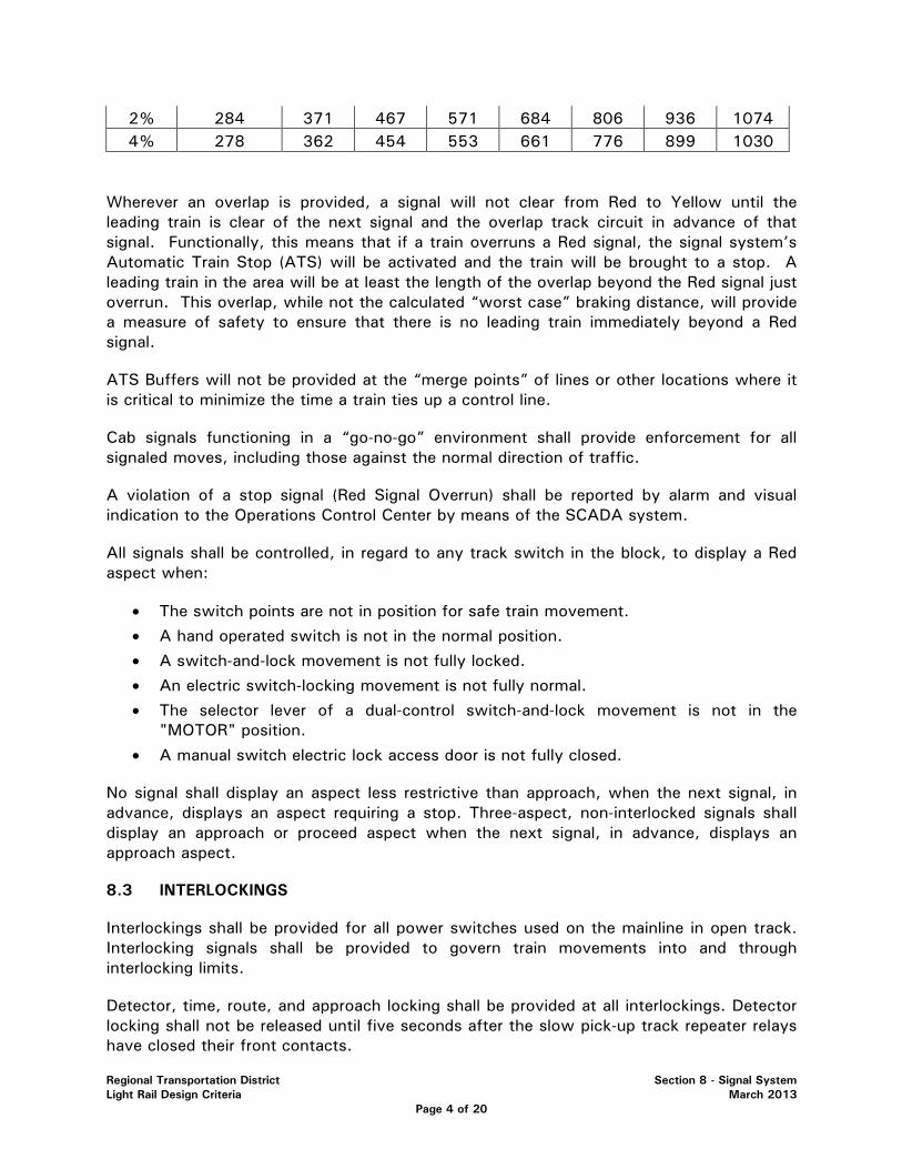
Regional Transportation District Section 8 - Signal System Light Rail Design Criteria March 2013
Page 4 of 20
2% 284 371 467 571 684 806 936 1074 4% 278 362 454 553 661 776 899 1030
Wherever an overlap is provided, a signal will not clear from Red to Yellow until the leading train is clear of the next signal and the overlap track circuit in advance of that signal. Functionally, this means that if a train overruns a Red signal, the signal system’s Automatic Train Stop (ATS) will be activated and the train will be brought to a stop. A leading train in the area will be at least the length of the overlap beyond the Red signal just overrun. This overlap, while not the calculated “worst case” braking distance, will provide a measure of safety to ensure that there is no leading train immediately beyond a Red signal.
ATS Buffers will not be provided at the “merge points” of lines or other locations where it is critical to minimize the time a train ties up a control line.
Cab signals functioning in a “go-no-go” environment shall provide enforcement for all signaled moves, including those against the normal direction of traffic.
A violation of a stop signal (Red Signal Overrun) shall be reported by alarm and visual indication to the Operations Control Center by means of the SCADA system.
All signals shall be controlled, in regard to any track switch in the block, to display a Red aspect when:
• The switch points are not in position for safe train movement.
• A hand operated switch is not in the normal position.
• A switch-and-lock movement is not fully locked.
• An electric switch-locking movement is not fully normal.
• The selector lever of a dual-control switch-and-lock movement is not in the "MOTOR" position.
• A manual switch electric lock access door is not fully closed.
No signal shall display an aspect less restrictive than approach, when the next signal, in advance, displays an aspect requiring a stop. Three-aspect, non-interlocked signals shall display an approach or proceed aspect when the next signal, in advance, displays an approach aspect.
8.3 INTERLOCKINGS
Interlockings shall be provided for all power switches used on the mainline in open track. Interlocking signals shall be provided to govern train movements into and through interlocking limits.
Detector, time, route, and approach locking shall be provided at all interlockings. Detector locking shall not be released until five seconds after the slow pick-up track repeater relays have closed their front contacts.
Regional Transportation District Section 8 - Signal System Light Rail Design Criteria March 2013
Page 5 of 20
All non-interfering train movements, through interlockings, shall be permitted simultaneously.
Interlocking design shall comply with principles and accepted practices of the American Railway Engineering and Maintenance-of-Way Association (AREMA).
Specifications will require:
• Open architecture type PLC’s similar to Allen-Bradley PLC’s, at all interlockings
• Rail heaters, similar to the ones manufactured by Thermon, which exist on RTD’s system, at all power switch locations
Dual microprocessors and dual power will be specified at junction locations. Single microprocessors and one source of AC power will be required at all other locations.
8.3.1 EMERGENCY CROSSOVERS
The overall theory of operation is that the emergency crossovers will function largely as they do today, except that the hand thrown switches and electric locks will be replaced by mainline power switch machines. No double red signal protection will be provided.
Unlike other RTD interlockings, the emergency crossovers will have only two modes of control. In both cases the home signals will normally be red and approach requested and lit. Light-out protection will be provided for all signals.
• TWC – Unlike other RTD interlockings there will be no provisions for TWC control.
• Automatic/Centralized Traffic Control (CTC) – All emergency crossovers shall be provided with remote control through the SCADA system. During normal operations, control of the emergency crossovers will be automatic. As a train approaches the interlocking, a request for a normal (straight ahead) route through the interlocking will be generated by track circuit occupancy. This request will be generated far enough in advance of the train that the operator sees only green approach and home signals. A request for a normal route will lock the switches in the normal position.
If the Controller wants the train to crossover it will be his responsibility to contact the train and tell him to stop at the home signal even though he has a clear aspect. Once the Controller is satisfied that the train to be crossed over is stopped at the home signal he will change the relay house condition from automatic to Central mode, cancel the signal, and request a reverse (crossover) route. This will cause the home signal to go red and begin running a 30 second ASR timer.

Regional Transportation District Section 8 - Signal System Light Rail Design Criteria March 2013
Page 6 of 20
When the timer has expired the switch will unlock and reverse. Once the switch is in the reverse position the Controller will be able to request the home signal for the new route if desired. When the crossover route is requested the opposing signal on the opposite track will be put to red. The Controller will also have the option to cancel the signal, and after running time return the switch to the normal position and clear the same signal for a straight route. The intent is that the Controller will have complete control of the interlocking. None of the emergency crossovers will “self-restore” to normal unless the Controller has returned the bungalow to the automatic mode.
• All emergency crossovers shall be provided with a local control panel for manual operation.
Signals for moves in the normal direction will check that the switch is locked, the OS track is clear, and trains are far enough ahead to allow for a clear aspect. For reverse direction moves the signals are much more limited. They will check that the switch is locked reverse and the OS track is clear but that is all. They will not look into the block on the opposite track. For crossover moves, the system is basically a manual block operation using power switches with the Controller being responsible for preventing all unsafe conditions.
8.3.2 SINGLE TRACK TERRITORY
In areas of the alignment where there is a single track with trains operating in both directions the Signal System shall employ standard “traffic circuits” to vitally determine the direction of train movements within the area at any given time.
8.4 HIGHWAY GRADE CROSSING WARNING
Warning devices for highway grade crossings shall be installed at locations as prescribed by a project specific engineering study as outlined in the Manual on Uniform Traffic Control Devices. The study and its results shall be provided as the design requirements for the projects grade crossings. Each such crossing shall include automatic gates, LED flashing lights, bells, signs, approach and island track circuits, emergency batteries and associated circuitry, cabling and relay houses as required. Crossing gates shall be Western-Cullen-Hayes model number 3593-131 with “Gate Keeper” protective devices or approved equal. All crossings shall be equipped with island circuits.
The design of each crossing shall be specific to that site and shall provide a minimum of 25 seconds warning time, from the time that the lights first begin to flash until the time that a train traveling at design/planning speed enters the crossing. Additional warning time shall be provided to account for long crossings in accordance with AREMA standards. The design of the crossing circuitry shall avoid unnecessary delays to motorists. Where necessary, the grade crossing warning system shall provide advanced preemption for adjacent traffic lights to avoid automobiles forming a queue across the tracks. In double track areas, not signaled for double direction operation, of the alignment no reverse running approaches will be provided. In single track areas approaches will be provided in both directions. A red marker signal will be furnished at rail connections for the island circuit for moves in the reverse direction.

Regional Transportation District Section 8 - Signal System Light Rail Design Criteria March 2013
Page 7 of 20
A center lane divider island with a flashing light signal shall be installed at all grade crossings to aid in the prevention of traffic gate runarounds. At crossings where it is not possible to construct a center median, quad (4) gates will be used. Exit Gate Clearance Time (EGCT) is defined as the time required to allow vehicles to clear the crossing before lowering the exit gates at crossings equipped with exit gates. EGCT shall consist of a minimum of one second for each ten feet, or portion thereof of Clearance Distance (CD) at the crossing. Control of the leaving gates will be via a timer rather than a vital presence detector. Crossings with permitted train speeds in excess of 30 mph shall have warning signs stating “High Speed Trains”. All crossings will be equipped with one flashing yellow light facing away from highway traffic to indicate to the train operator that the gates are functioning. Provisions for the installation of video monitoring equipment shall be installed at each grade crossing. Circuits will be arranged to send 1) Gate Active, 2) Gate Down, and 3) Gate Down Alarm indications into the SCADA System. Highway grade crossing warning devices will be installed consistent with American Railway Engineering and Maintenance-of-Way Association (AREMA) Signal Manual and Manual on Uniform Traffic Control Devices Standards.
The control circuits for the approach signals nearest to each crossing shall be arranged such that if the “key-up” feature has been activated at that crossing the signals shall display a red aspect.
At all gated crossings, second train signs and gate control pushbuttons shall be used.
8.5 TRAIN-TO-WAYSIDE COMMUNICATIONS (TWC) SYSTEM
RTD's LRVs are equipped with a Train-to-Wayside Communication (TWC) system. The carborne portion of the TWC system consists of two transponders (one for each end of the LRV), and two car control units (one for each cab). The wayside portion shall consist of an inductive loop antenna and a wayside interrogator. The wayside interrogator, through the wayside loop antenna, shall constantly transmit a message asking that any carborne TWC transponder, in the immediate area, identify itself. A carborne TWC transponder receiving this message shall respond by transmitting a serial 19-bit message, identifying the LRV's car number, the train number, route number (destination), and other information. Thumb-wheel switches and push buttons in each cab are provided to train operators to enter the route number and train number of their consist and other requests such as switch call and preempt call.
A TWC system, compatible with the LRV equipped TWC system, shall be installed at all interlockings, at all passenger stations adjacent to highway crossings and provisions made for all passenger stations in street running, and at all power switches in street running, to allow train operators to enter switch call and route requests. Use of the TWC system shall be the primary method of entering route, switch requests, and SCADA train identification at those locations.
A TWC loop and handhole shall be installed at all highblocks for improved SCADA control of LRV movements. It shall include a TWC antenna and conduits to a nearby signal case for future utilization.

Regional Transportation District Section 8 - Signal System Light Rail Design Criteria March 2013
Page 8 of 20
The TWC wayside interrogator operating frequency shall be 100 Khz. It must be capable of recording and storing data history to include all inputs and outputs for download and review for a backlog of at least 48 hours from the time of download. Data acquisition and unit programming must be easily accomplished by a signal technician with moderate laptop computer skills. Installation shall include one interrogator for every four (or fewer) wayside TWC loops at a location. The wayside loop shall be a single wire loop mounted between the rails with the end to end dimension of the loop being 15 feet for mainline loops and 6 feet for yard loops. The loop shall be mounted no higher than top of rail and no lower than 6 inches below top of rail. In open track areas the loop shall be housed in a manufactured, prefabricated fiber glass enclosure.
Assignment of destination codes shall take into consideration future expansion plans of the LRT system. Assignments shall be developed to provide a logical progression of destination codes throughout RTD's LRT expansion plans.
Additional TWC loops shall be installed at all merge points and other locations as necessary to provide consistent train tracking as required by the Communications System.
8.6 STANDARDS AND CODES
The signal system shall be designed, constructed and tested in accordance with the latest revision at the time of award of contract of the following codes and standards:
• U.S. Code of Federal Regulations (CFR), Title 49, Part 236 Rules Standards and Instructions Governing the Installation, Inspection, Maintenance and Repair of Signal and Train Control Systems, Devices and Appliances.
• U.S. Code of Federal Regulations (CFR), Title 49, Part 234 Grade Crossing Signal System Safety.
• American Railway Engineering and Maintenance Association (AREMA) o Signal Manual of Recommended Practice o American Railway Signaling Principles and Practice o Communication Manual of Recommended Practice o Typical Circuits Representing Current Practice for Railway Signaling
• American Public Transportation Association (APTA)
• Rules and Regulations of the Colorado Public Utilities Commission (PUC)
• American Railroad Engineering Association (AREA)
• National Electrical Code (NEC)
• National Electrical Safety Code (NESC)
• Insulated Cable Engineers Association (ICEA)
• American Society for Testing and Materials (ASTM)
• American National Standards Institute, Inc. (ANSI)
• Underwriters Laboratories, Inc. (UL)
• U.S. Department of Transportation, Federal Highway Administration, Manual on Uniform Traffic Control Devices (MUTCD) and Colorado Supplement

Regional Transportation District Section 8 - Signal System Light Rail Design Criteria March 2013
Page 9 of 20
• Institute of Electrical and Electronic Engineers (IEEE)
8.7 SAFETY DESIGN
Train safety shall be the prime consideration in the design of the signal system and in the selection of its components, including relays and other devices with moving parts, insulated wire, wire terminals, binding posts, housings, conduits, resistors, capacitors, transformers, inductors and other similar items. The entire signal system shall meet the requirements of this section. Circuit design shall conform to the "American Railway Signaling Principles and Practices" of the AREMA Communication and Signal Section.
The following requirements shall govern the design of the portions of the system or a subsystem which affect train safety:
• Only components which have high reliability and predictable failure modes and rates and which have been proven in conditions similar to the projected service shall be utilized.
• Components shall be combined in a manner that ensures that a more restrictive rather than a permissive condition will result from component failures.
• All circuits which are not confined to one housing and which affect safety shall be double-wire, double-break, except signal and switch indicator light circuits.
• The design shall be based on closed circuit principles.
• Component or system failures shall cause a more restrictive signal indication than that permitted with no failure. The built-in fault detection and alarm generation capability are preferred.
• System safety design shall be such that any single independent component or subsystem failure will result in a safe condition. Failures that are not independent (those failures which in turn always cause others) shall be considered in combination as a single failure and will not cause an unsafe condition.
• Any latent failure of the equipment, that is a failure, which by itself does not result in an unsafe condition, but which in combination with a second or subsequent failure could result in an unsafe condition, must be detected and negated within a stipulated time period.
• Electronic circuit design shall insure that the following types of component failures have a more restrictive rather than a permissive effect: o Two terminal devices: open, short, partial open or short o Multi-terminal devices: combination of opens, shorts, partial opens and/or partial
shorts
• Wherever possible, built-in checks shall be included that impose a restriction and/or actuate an alarm whenever a device fails to assume its most restrictive position when conditions require that it should.
• Redundant design by itself shall not be considered an acceptable method of achieving design safety.
Regional Transportation District Section 8 - Signal System Light Rail Design Criteria March 2013
Page 10 of 20
8.8 HEADWAYS & BLOCK LAYOUT
The design of the LRT signal system shall provide for minimum train headways of 135 seconds, or less. On single track portions of an alignment the headways shall be designed to meet the stated requirements of the operating department for the individual line in question rather than being exactly 135 seconds. Headway is defined as the length of time taken for a given automatic block signal to upgrade to a permissive (restricting or approach) aspect after a leading train has passed that signal at normal track speed. Maximum train length will be 4 cars under normal conditions. Three-aspect signals are required to provide information about the aspect displayed by the next signal ahead so as to avoid the necessity for always approaching it while prepared to stop.
Wherever it is displayed, a stop indication shall be an absolute signal, requiring that train operators bring their trains to a full stop and call the LRT controller for authorization to pass the signal at restricted speed (i.e., prepared to stop, within one-half the range of vision, short of anything that may so require a stop).
Signal system design headways are calculated without regard for variations in vehicles, weather conditions or individual operators. Signal system design headways will provide for sustained five minute scheduled headways.
8.9 SAFE BRAKING DISTANCE
Safe braking distances shall be calculated using code recognition time consistent with the requirements of the wayside and on-board equipment, a minimum adhesion which would allow a deceleration rate on level tangent track of 1.95 MPHPS and a 35% (distance) safety margin. The assumed deceleration rate shall be reduced on downhill grades to compensate for the effects of gravity. In addition, all safe braking distance calculations in open-track territory shall assume a LRV entry into the governed area at a maximum authorized speed plus 4 mph.
8.10 ENVIRONMENTAL CONSIDERATIONS
All equipment shall be designed to operate from a minimum temperature of -40°C(-40°F) (ambient) to a maximum temperature resulting from a combination of an ambient temperature, maximum sun loading and maximum normal internal heat generation, of 70°C(158°F).
8.11 SERVICE PROVEN EQUIPMENT AND DESIGN
All signal equipment shall be proven in similar North American railroad or transit service. The signal system shall have an expected service life of 40 years at the specified level of service. Achievement of this useful life shall be through the use of off-the-shelf proven hardware. Each major component shall incorporate provisions to allow for functional and physical interchangeability of replacement spare parts.
Regional Transportation District Section 8 - Signal System Light Rail Design Criteria March 2013
Page 11 of 20
8.12 TRAIN DETECTION
Train detection in the ABS sections and at interlockings shall be accomplished by using one of the following types of track circuits.
• Two-rail, shunt type 60 Hz, phase selective track circuits with impedance bonds and two-element vital vane relays. In areas where the potential for 60 Hz interference exists, phase selective track circuits of a different frequency shall be used.
• Solid state electronic, coded track circuits suitable for use in overhead propulsion territory.
• Equipment shall be compatible with existing RTD equipment.
• Verify that track circuit selected for use is compatible within the electromagnetic environment that exists on the RTD system. The known electromagnetic environment of the RTD system includes; close proximity to high voltage transmission lines. ithin the system there will exist harmonics generated by the traction power system, by the vehicle propulsion system and various communication systems.
•
Single-rail (not to exceed 60 feet in length) or double rail, shunt-type power frequency phase selective track circuits shall be used to detect train presence in embedded track.
Audio-frequency, overlay, shunt-type track circuits shall be used for train detection in the control of highway grade crossing warning equipment.
The design of the LRV propulsion and traction systems and selection of track circuit frequencies and modulation schemes shall be coordinated to preclude interference between the LRV and the signal system.
A shunt with a resistance of 0.2 ohm or less at any point between the two rails of any track circuit shall cause the track circuit to indicate train occupancy. Shunt fouling shall not be allowed. Multiple track relays or series fouling shall be used for all turnouts, with the exception of the two (or four) turnouts used in crossovers between mainline tracks. Voltage regulating transformers in the feed to the track may be used or additional track circuits may be installed, if necessary, to provide this shunting capability. Impedance bonds shall be used to enhance track circuit stability.
Wherever possible, track circuit lengths, crossbonds and TPSS returns shall be coordinated to provide broken rail protection.
TRACK CIRCUIT NAMING a. Overlay track circuits shall be named after the switch for which they protect b. All other track circuits shall be named off the signal in advance of it
Regional Transportation District Section 8 - Signal System Light Rail Design Criteria March 2013
Page 12 of 20
8.13 SIGNALS & SWITCH INDICATORS
8.13.1 COLOR LIGHT SIGNALS
With the exception of those signals noted below and two-aspect switch indicating signals, standard railway color light, high signals, including backgrounds and split base junction boxes shall be provided for ABS sections and interlockings in open-track sections. Signals at station platforms which do not have to be viewed from a distance may be dwarf-type railway color light signals on pedestal bases. Low, dwarf-type railway color light signals may be used for non-normal moves.
8.13.2 SIGNAL ASPECTS
Each signal aspect shall have an indication (meaning), which is the same wherever it is displayed throughout the LRT system. The system shall have two-aspect and three-aspect signals.
Fundamental aspects of color light signals shall consist of the following:
TABLE 8A - FUNDAMENTAL ASPECTS OF COLOR LIGHT SIGNALS
Name Aspect Indication
Stop Red Light Stop
Approach Yellow Light Proceed on primary route prepared to stop at next signal
Proceed Green Light Proceed on primary route at permitted speed
Diverging Flashing Yellow Light Proceed on secondary route prepared to stop at next signal
Diverging Flashing Green Light Proceed on secondary route at permitted speed
Exit Red over Yellow Proceed out of signalized territory into yard or storage track
TABLE 8B - STREET RUNNING AREA SIGNALS
Name Aspect Indication
Stop Red Stop
Proceed Yellow Divergent track clear; proceed in street running rules
Proceed Green Proceed on primary route at permitted speed
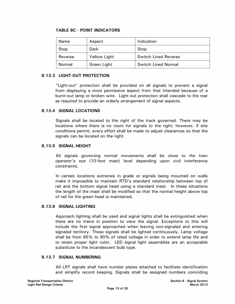
Regional Transportation District Section 8 - Signal System Light Rail Design Criteria March 2013
Page 13 of 20
TABLE 8C - POINT INDICATORS
Name Aspect Indication
Stop Dark Stop
Reverse Yellow Light Switch Lined Reverse
Normal Green Light Switch Lined Normal
8.13.3 LIGHT-OUT PROTECTION
"Light-out" protection shall be provided on all signals to prevent a signal from displaying a more permissive aspect from that intended because of a burnt-out lamp or broken wire. Light out protection shall cascade to the rear as required to provide an orderly arrangement of signal aspects.
8.13.4 SIGNAL LOCATIONS
Signals shall be located to the right of the track governed. There may be locations where there is no room for signals to the right; however, if site conditions permit, every effort shall be made to adjust clearances so that the signals can be located on the right.
8.13.5 SIGNAL HEIGHT
All signals governing normal movements shall be close to the train operator's eye (10-foot mast) level depending upon civil interference constraints.
In certain locations extremes in grade or signals being mounted on walls make it impossible to maintain RTD’s standard relationship between top of rail and the bottom signal head using a standard mast. In these situations the length of the mast shall be modified so that the normal height above top of rail for the green head is maintained.
8.13.6 SIGNAL LIGHTING
Approach lighting shall be used and signal lights shall be extinguished when there are no trains in position to view the signal. Exceptions to this will include the first signal approached when leaving non-signaled and entering signaled territory. These signals shall be lighted continuously. Lamp voltage shall be from 85% to 90% of rated voltage in order to extend lamp life and to retain proper light color. LED signal light assemblies are an acceptable substitute to the incandescent bulb type.
8.13.7 SIGNAL NUMBERING
All LRT signals shall have number plates attached to facilitate identification and simplify record keeping. Signals shall be assigned numbers coinciding

Regional Transportation District Section 8 - Signal System Light Rail Design Criteria March 2013
Page 14 of 20
with the signals physical track distance from the northern terminus of the Downing Street station and a suffix letter indication of the associated corridor. Signal numbers shall reflect this distance rounded to the nearest 100th of a mile. Example: Signal 379 in the Central Corridor is approximately 3.79 track miles from the Downing Street terminal and would be labeled S379CC. Signal plates will have black background with white reflective lettering.
Signal number signs will be 8 inches high x 18 inches wide, and have a 0.40 black aluminum background with 6-inch tall white vinyl letters and numbers.
8.13.8 RED SIGNAL VIOLATION
All signals shall be equipped with a positive means of detecting a red signal violation. Red signal violations shall be recorded on the local event recorder, as well as being sent to the central office via the SCADA system.
8.13.9 CAB SIGNALS
All signals shall have an associated enforcement function provided by a “go/no-go” cab signal system. In single track areas, moves in both directions shall be protected by the cab signal system. In double track areas, not signaled for double direction operation, only moves in the normal direction shall be protected by the cab signal system.
8.14 MAINLINE TRACK SWITCHES
8.14.1 TRACK SWITCHES IN OPEN-TRACK
A) MANUAL TRACK SWITCHES
Manually operated switches in signaled territory shall be equipped with switch and lock movements with operating rods, lock rods and point detectors, and electric switch locks as required by Federal Railroad Administration (FRA) requirements. Removing a padlock from the electric switch lock and opening the front access door shall put protecting signals to stop and shall start a timer to ensure clearance of trains that may have just passed the protecting signals. Expiration of the 30 second timer shall permit the switches to be unlocked and hand lined.
All hand throw switches at the ends-of line will be equipped with hydraulic switchmen.
B) POWERED TRACK SWITCHES
Ballasted
Switches shall be powered by dual control (motor driven/manual) switch machines on open trackwork. Power for the dual control switch machines

Regional Transportation District Section 8 - Signal System Light Rail Design Criteria March 2013
Page 15 of 20
shall be from the signal power line or from commercial 120 VAC power source, rectified to 110 VDC. Switch machines shall be equipped with operating rods, lock rods and point detectors. Electric switch and lock movements shall be Ansaldo STS Type M23-A, Alstom Signal Company model 5F, or approved equal. Power switches on #20 or larger turnouts shall also be equipped with a midpoint circuit controllers and helper rods.
C) SWITCH HEATERS/SNOW MELTERS
Switch heaters are to be provided and installed by the Signal Contractor at designated locations where the presence of ice and snow could affect rail service. Switch heaters shall be operated automatically or manually and an indicator shall be provided at the control equipment enclosure to indicate that the unit is on. Snow melters shall be powered from a 208 or 240 VAC source with heater pads wired in parallel sufficiently rated to keep the switch points and stock rails free of snow and ice.
8.14.2 Track Switches in Paved Track
A) MANUAL TRACK SWITCHES
Manual track switches shall be equipped with toggle type switch movements. Facing-point switches shall be equipped with switch circuit controllers and switch indicator as determined by RTD
B) POWERED TRACK SWITCHES
Embedded
For in street running switches designed for embedded in street applications shall be utilized. Switches shall be powered off a rectified AC source originating from the control enclosure. Power shall be a nominal 120 VAC. Switch machines shall be equipped with operating rods and point detectors. Switches shall be Western Cullen Hayes, electro-hydraulic, or approved equal.
A successful operating record shall require a minimum of 3 years of successful operation on a comparable North American transit system or railroad, as determined and approved by RTD.
8.14.3 TRACK SWITCH NUMBERING
For Extension Corridors (i.e. I-225, Southeast, Southwest)
All LRT switches shall have number plates attached to facilitate identification and simplify record keeping. They shall follow the same numbering pattern as is already in place for that particular Corridor. Switch number identification plates will be 6 in tall and painted white.
Regional Transportation District Section 8 - Signal System Light Rail Design Criteria March 2013
Page 16 of 20
FOR THE WEST CORRIDOR
All LRT switches shall have number plates attached to facilitate identification and simplify record keeping. Switches shall be assigned numbers coinciding with the switch’s physical track distance from the northern terminus of the Downing Street station followed by a suffix letter indication of either an “A” or “B” to designate its associated track. Example: Switch 1467 which is a turnout off of track B in the West Corridor is approximately 14.67 track miles from the Downing Street terminal and would be labeled SW1467B. Switch number identification plates will be 6 in tall and painted white.
FOR NEW CORRIDORS
All LRT switches shall have number plates attached to facilitate identification and simplify record keeping. For all NEW Corridors, switches shall be assigned numbers coinciding with the switch’s physical track distance from the northern terminus of the Downing Street station followed by a suffix letter indication of either an “A” or “B” to designate its associated track. A second suffix shall accompany the “A” or “B” for the associated corridor. Switch numbers shall reflect this distance rounded to the nearest 100th of a mile. Example: Switch 1082 which is a turnout off of track A in the XX Corridor is approximately 10.82 track miles from the Downing Street terminal and would be labeled SW1082AXX. Switch number identification plates will be 6 in tall and painted white.
8.15 CONTROL CIRCUITRY
All safety circuits or logic shall be designed using vital relays and/or Vital Processors (solid state interlocking) of proven design and successful operating record.
Non-vital logic circuits may be controlled either by non vital relays or non vital solid-state logic controller or emulator.
The RTD preference is to eliminate relays to the maximum extent possible through the use of vital and non-vital microprocessor based systems.
All relays shall plug into separate relay bases. All non-vital relays shall be identical. All relays shall be furnished with at least one spare independent front-back contact.
The use of diodes, capacitors, or resistors to change a vital relays timing characteristics shall not be allowed for vital relays. All such timing characteristics shall be accomplished magnetically.
8.16 VITAL MICROPROCESSOR INTERLOCKING SYSTEMS
If interlockings are not controlled by vital relays, then Vital Microprocessor Interlocking Systems (VMIS) shall be employed to execute all vital safety signal system functions. The

Regional Transportation District Section 8 - Signal System Light Rail Design Criteria March 2013
Page 17 of 20
VMIS system shall be compatible with the existing microprocessor equipment currently in service on the RTD light rail system.
The VMIS shall be capable of operating in a light rail transit environment including exposure to temperatures, humidify and vibration. The VMIS shall be capable of operation at temperature of -40°C(-40°F) to +70°C(+158°F) at 90% humidity non-condensing.
The VMIS software systems shall be segregated into two independent software levels as follows:
• Executive Software shall consist of the coding that performs the input, internal and output operations that are defined within the individual interlocking application logic. The executive software shall be configured on a closed loop principle to ensure that the individual vital microprocessors operate in a fail-safe manner. The executive software shall reside in read only memory.
• Application Software shall be segregated from the executive software and consists of the vital signal logic defining a specific interlocking configuration. The application software shall derive its safety from signal circuit design practices similar to that used for relay logic. The application software shall be capable of being modified to reflect changes in a specific interlocking configuration by RTD signal engineering staff with basic computer skills. To perform these software modifications, the VMIS system shall incorporate an application software development system and software simulator in order that the modifications can be tested and verified prior to final implementation.
For large interlockings (more than four power switches and/or movable point frogs), the VMIS system shall be segregated into zones and configured in a manner that failure in one zone will not affect the operation of an adjacent zone. Redundant microprocessors (normal and hot standby) shall be provided at selected microprocessor interlocking locations and configured such that shut down of the primary microprocessor would automatically permit seamless transfer to the standby unit.
Individual VMIS units shall include both vital serial ports to interface with adjacent VMIS units, and non-vital serial ports for interface with the non-vital control system. Interface connections to wayside signal equipment shall be designed to function with existing RTD signal equipment operating at standard voltages for the type of equipment in service. Where necessary, the VMIS system shall include vital relays to provide interface to wayside signal appliances.
The VMIS shall be equipped with a data recorder and diagnostic system capable of being accessed on-site at the VMIS location, or remotely over telephone or dedicated data lines using a diagnostic terminal or standard laptop personal computer. Data shall be capable of being accessed remotely from the data recorder and in real time on-site directly from the VMIS equipment. The diagnostic system shall be capable of identifying a failure, the nature of the failure and failure location. In addition to the diagnostic system, individual cards including; input/output boards, central processor cards and internal power supply boards shall be equipped with indicator lights that illuminate when respective input/output devices or ports are active.
Regional Transportation District Section 8 - Signal System Light Rail Design Criteria March 2013
Page 18 of 20
The VMIS system shall be configured to operate from local available signal system power supply sources. Individual VMIS units shall be equipped with protection against unwarranted power surges at the power supply input terminals. The VMIS units shall also be protected against high levels of electric noise transmitted from external sources including radio, vehicle propulsion systems and hi-tension commercial power lines. Lightening protection including appropriate lightening arresters and equalizers shall be provided at all input terminals interfacing with wayside signal appliances.
VMIS units shall be modular and consist of stand alone card files capable of being mounted in standard instrument racks. Included in the instrument rack shall be all signal equipment required to provide a complete stand alone system.
VMIS units shall communicate via serial or IP to the Communications System.
8.17 SIGNAL POWER
8.17.1 POWER LINE
Primary power will be provided to the various signal locations by individual power drops provided by the local utility. Because the track relays shall be of the phase-selective, two-element type, it shall be necessary for a fixed-phase relationship to be maintained between adjacent track circuits and between the two ends of each individual track circuit. Reference voltage between locations may be required to be provided via line wire.
8.17.2 FREQUENCY CONVERTERS
If different frequency phase selective track circuits (other than 60 Hz) are determined to be necessary as the result of electromagnetic interference studies, appropriate frequency converters of solid state design shall be provided.
8.17.3 BATTERIES
All grade crossing warning equipment shall be provided with emergency batteries. Nickel-cadmium or sealed lead-acid batteries, with a minimum capacity of 240 Ampere-hours shall be provided. Separate battery banks for logic and gates flashers shall be provided. Battery backup shall provide sufficient power to allow the crossing to operate for a minimum of 8 hours without AC power under normal operating conditions.
8.17.4 REDUNDANT SIGNAL POWER
Redundant signal power shall be provided at junctions or other operational critical areas as defined by RTD.
Regional Transportation District Section 8 - Signal System Light Rail Design Criteria March 2013
Page 19 of 20
8.18 SCADA INTERFACE
Each signal equipment room/case shall be equipped with a SCADA interface to provide the following controls and indications to the SCADA system:
• TWC Indications for all Passing Trains
• Track Circuit Occupancy Indications
• Switch or Crossover Position Indications
• Electric Switch Lock Indications
• Switch Heater Indications and Controls
• Signal Aspects Indications
• Route Request Indications and Controls
• Interlocking Mode of Operation Indications and Controls
• Commercial Power Status Indications
• Signal Power Status Indications
• Signal Power Line Indications and Controls
8.19 LIGHTNING AND TRANSIENT PROTECTION
Track circuits shall be protected from lightning per AREMA Communications & Signals Manual Part 11.3.1. Grounding electrodes rods shall be provided and installed in the signal rooms/case. Connections between arresters, other signal equipment, and grounding electrodes shall be per AREMA Communications & Signals Manual Part 11.3.1, except that all connections to grounding electrodes shall be by exothermic welding.
All electronic and solid state devices shall have effective internal and separate external surge protection. High-voltage lightning arresters shall be applied to commercial power connections.
8.20 WIRE AND CABLE
Station-to-station and signal-room-to-field equipment signal wires in the signaled areas shall not be combined in the same cable or conduit with signal power or communication circuits. In general, conduit located in an underground duct bank shall be provided.
Station-to-station and signal-room-to-field equipment signal conductors shall be #14 AWG or larger conductors with 5/64" of 90°C ethylene-propylene rubber compound insulation. Multiple conductor cables shall have an outer jacket of extruded, black, low density, high-molecular weight polyethylene.
Case wiring shall be #16 AWG or larger and shall have either 90°C ethylene-propylene rubber compound or Teflon insulation. Wire, cable and its installation shall comply with the applicable requirements of the AREMA Signal Manual. A minimum of 10%, but not less than 2 spare conductors, shall be required in each cable.
Regional Transportation District Section 8 - Signal System Light Rail Design Criteria March 2013
Page 20 of 20
“Composite” cable is acceptable for use on RTD. Conductors of various sizes may be included into a single cable with one overall outer jacket provided the cable meets all of the applicable AREMA standards.
8.21 LOCATION OF SIGNAL EQUIPMENT
Signal system equipment shall be located in wayside houses. Wayside cases shall be used only in the event it is physically impossible to locate a house at the required location.
All signal equipment, including signals, cases and houses shall be designed clear the LRV clearance envelope by a minimum of 6 inches provided sufficient ROW is available to allow for construction tolerances. Equipment shall not violate the clearance envelope as defined in Section 4 - Trackwork
Doors of signal equipment cases and houses shall be restrained from opening to a position less than 6 inches from the LRV clearance envelope.
In general, relay houses shall be oriented so that the personnel door opening faces along track in the direction of the normal oncoming train movement on the near track. Relay houses that are greater than 20 feet from edge of building to field side of near rail may have the personnel door opening facing perpendicular to the near track.
Relay houses that are located at the ends of platforms and between the tracks shall have the personnel door opening facing along track towards the platform. Relay houses shall be offset towards the normal exiting side of the station in order to minimize the visual obstruction of the LRV operator as the train approaches the station on its normal entrance track.
All relay house locations shall be coordinated with RTD
Relay houses shall be located in such a way as to not obstruct the train operators or motorists (insofar as grade crossing warning equipment is concerned) view of the governing signal.
To the maximum extent possible, all signal relays shall be located in signal equipment rooms/cases at each passenger station.
So far as possible ABS signals shall be located approximately 50 feet from the exiting end of station platforms.
8.22 INTRUSION DETECTION EQUIPMENT
Intrusion detection equipment, if required, shall be compatible with the current RTD seismic sensing technology.
RTD Design Guidelines & Criteria Section 9 – Traction Electrification System Light Rail Design Criteria March 2013
Page 1 of 36
SECTION 9 - TRACTION ELECTRIFICATION SYSTEM 9.1 GENERAL ..................................................................................................................... 2 9.2 FUNCTIONAL REQUIREMENTS ..................................................................................... 2 9.3 DESIGN REQUIREMENTS .............................................................................................. 3
9.3.1 TRACTION POWER SYSTEM (TPS) ............................................................................ 3 9.3.2 TRACTION POWER FEEDER SYSTEM (TPFS) .............................................................. 5 9.3.3 OVERHEAD CONTACT SYSTEM (OCS) ...................................................................... 6
9.4 STANDARDS AND CODES ......................................................................................... 17 9.5 PRODUCT REQUIREMENTS ........................................................................................ 17
9.5.1 TRACTION POWER SUPPLY SYSTEM ...................................................................... 17 9.5.2 OVERHEAD CONTACT SYSTEM (OCS) .................................................................... 23
9.6 DESIGN PARAMETERS ............................................................................................... 27 9.7 CONDUIT AND DUCTBANKS ...................................................................................... 28
9.7.1 RACEWAY AND DUCTBANK SYSTEM ..................................................................... 28
Regional Transportation District Section 9 – Traction Electrification System Light Rail Design Criteria March 2013
Page 2 of 36
SECTION 9 - TRACTION ELECTRIFICATION SYSTEM
9.1 GENERAL
The Traction Electrification System (TES) provides electrical power to a Light Rail Vehicle (LRV) by the means of Traction Power System (TPS) and the Overhead Catenary System (OCS). The TPS consists of the Traction Power Substations (TPSS) and the Traction Power Feeder System (TPFS). The TPFS includes both the positive and negative feeder cables and the respective conduit systems as determined by the System wide electrical requirements. The LRV will collect current from the contact wire by means of pantographs and will return the current to the substations via the running rails.
The TPS consists of traction power substations located along the Light Rail Transit (LRT) lines, which receives primary power from the local power utility company. The substations include all the equipment necessary to transform and rectify the primary AC three-phase power to DC traction power. Traction power will be supplied to the OCS via positive underground feeder cables. The negative return underground feeder cables shall be connected to the running rails via impedance bonds.
The OCS shall consist of an arrangement of steel poles, cantilever assemblies and conductors installed over the rail tracks, to deliver nominal 750 Volt DC power supplied by the Traction Power System, to the pantograph of each train. The OCS shall be double insulated. Unless directed otherwise by RTD simple catenary shall be used on mainline applications and single contact wire shall be used for all yards and shops. Single contact wire style shall be used in aesthetically sensitive areas such as city center streets and malls in which cases the single contact wire will be electrically reinforced by underground parallel feeder cables, with cable risers to the OCS at suitable intervals. The use of a underground feeder to support a single contact wire is much more expensive than using a simple catenary style and therefore shall only be used where directed by RTD.
The traction power substations shall provide power to the OCS at sectionalizing points. The OCS shall normally operate as a dual multi-feed system for the full length of the main lines with each track being electrically separated from the other. The OCS for the maintenance facility and storage tracks shall operate independently from the main line OCS and shall have its own traction power substations. The mainline tracks will be isolated from ground and connected to the negative bus at the TPSS. The yard and shop tracks will be grounded and separated from the mainline tracks by insulated rail joints.
9.2 FUNCTIONAL REQUIREMENTS
The traction electrification system shall maintain the OCS voltage above the minimum allowable value. The spacing of the substations shall be established to prevent the temperature of the OCS conductors from exceeding the limit recommended by the conductor manufacturer. The OCS shall be designed to ensure that the LRVs operate with all pantographs in continuous contact with the contact wire up to the maximum allowable track speed. The design shall avoid sudden changes in contact wire height that would cause arcing during current collection.
All traction power and distribution system equipment shall be designed taking into account the effects of the harmonic content of the traction load, the highly fluctuating pattern of traction current, and system faults. The TES shall be designed for a minimum functional
Regional Transportation District Section 9 – Traction Electrification System Light Rail Design Criteria March 2013
Page 3 of 36
life expectancy of thirty (30) years. All traction power substations shall meet the harmonic requirements of IEEE 519.
9.3 DESIGN REQUIREMENTS
9.3.1 TRACTION POWER SYSTEM (TPS)
The TPS includes the traction power substations and the pad mounted disconnects located adjacent to the substations from which the underground positive feeder cables run directly to the OCS feeder poles and the underground negative return cables run directly to the track rails in non-signalized territory and to the rails through impedance bonds in signalized territory.
Designer shall review past traction power systems designs in order to understand and use past design principles to maintain consistency in designs.
9.3.1.1 SUBSTATION SPACING AND LOCATION
Traction power substation spacing shall be based on the system load flow simulation. The substations shall be located so that the distribution system voltage does not drop below the minimum level requirements, the temperature of the distribution system conductors does not exceed the maximum allowable value, and the rail voltages do not exceed the maximum permissible values.
9.3.1.2 SYSTEM LOAD FLOW SIMULATION
The design of the TES shall be based on a computer-aided load flow simulation. The simulator shall simulate operation of the trains along the alignment and calculate all necessary parameters for the electrification system design. Four car trains shall be simulated to operate on the system at the minimum projected headways, as specified by RTD, under normal and individual substation outage conditions, with the cars loaded to AW3, as defined in Section 1. Under these operating conditions the TES design shall be shown to operate successfully within the required design parameters and the voltage at the trains shall not fall below 525 Vdc.
The input data shall include track gradients, track speed limits, passenger station locations and station dwell times, as well as the electrical and mechanical characteristics of the trains. Further, the input data shall represent the utility electrical system, the traction power substations, the distribution system and the power return system.
The output data shall include train operational data such as speed, distance traveled, power demand and energy consumption for each station-to-station run. For each substation, the results shall include average power output, energy consumption, rectifier current and current for each feeder breaker. For each substation to substation section of the, line the results shall include voltage profile and current flow in each OCS section. Calculations for maximum substation bus current, feeder

Regional Transportation District Section 9 – Traction Electrification System Light Rail Design Criteria March 2013
Page 4 of 36
cable size, equipment temperature rating and OCS conductor temperature shall be performed.
9.3.1.3 SYSTEM LOAD FLOW SIMULATION
Train Voltage (Positive Network)
• Unacceptable – below 525VDC
• Marginally Acceptable – between 525VDC and 575VDC (requires RTD approval)
• Acceptable – above 575VDC
Rail Voltage (Negative Network)
• Normal Operation o Unacceptable – greater than 50VDC o Marginally Acceptable – between 40VDC and
50VDC (requires RTD approval) o Acceptable – below 40VDC
• Single Contingency (one TPSS out of service) o Unacceptable – greater than 90VDC (RTD substation
trip setting) o Marginally Acceptable – between 80VDC and
90VDC (requires RTD approval) o Acceptable – below 80VDC (RTD substation alarm
setting is 60VDC)
9.3.1.4 SUBSTATION INCOMING SERVICE
Incoming primary AC power to the TPSS may be supplied by the local power utility company at a nominal 13.2 kV, three phase, three wire, 60 hertz. The substations shall be connected by overhead lines or underground cables to the utility three-phase distribution network. The AC service and AC protection scheme shall be coordinated with the electrical utility.
One primary feeder shall supply each transformer rectifier. Each primary feeder shall originate from a different utility bus, and shall be as independent as possible. Feeders connected to the same utility bus shall not supply adjacent substations.
9.3.1.5 SUBSTATION TYPES
Each mainline substation shall have one transformer/rectifier unit and four DC feeder breakers unless otherwise specified by RTD. Substations located in the vicinity of mainline junctions shall have six DC feeder breakers.
9.3.1.6 SUBSTATION EQUIPMENT RATING
Regional Transportation District Section 9 – Traction Electrification System Light Rail Design Criteria March 2013
Page 5 of 36
The continuous rating of the mainline substation equipment such as the traction transformer, rectifier, circuit breakers and cables shall be based on the system load flow simulation.
Each mainline and yard substation shall be capable of supplying the following load cycle in accordance with NEMA standards:
• Constant temperature of all equipment shall be reached following operation at 100% rated power for a minimum of 2 hours.
• Equipment shall then be able to sustain a 150% overload for 2 hours with five evenly spaced periods of one minute each at 300% of rated load and one 5 second period at 450% of rated load, followed by a maximum short circuit current with duration equal to substation protective device clearing time.
• Equipment shall be capable of sustaining such an overload twice a day, once in AM peak and once in the PM peak periods.
The shop substation shall be capable of supplying 100% rated load continuously, 150% rated load for two hours following temperature stabilization at 100% load or 300% load for one minute following temperature stabilization at the 100% load.
9.3.1.7 TPSS SITE ACCESS, GRADING AND DRAINAGE
A minimum 12 foot wide access drive shall be provided to each substation from adjacent roadways. The access drive shall be surfaced with gravel or asphalt and shall not exceed a 6% grade. The surfacing material shall be as recommended by a Geotechnical Engineer or as required by local jurisdictions.
A minimum clearance of 10 feet shall be provided around the perimeter of each substation to permit access for RTD and maintenance vehicles and equipment. Clearance width may be reduced at one side of the substation with approval from RTD. A 72 inch high barbed wire chain link fence shall be provided around the perimeter of the substation and a 12 foot wide gate shall be provided at the access drive.
The fenced area shall be generally flat with finished grade sloping a minimum of 2% away from the building. Decorative stone (3/4 inch) shall be placed over geotextile weed barrier within the fenced area.
The Design Engineer shall analyze drainage at the substation and provide stormwater infrastructure as appropriate.
9.3.1.8 TPSS PROTECTION AND EMERGENCY SHUT-OFF OF TRACK SECTIONS
Circuit protection and transfer trip features between substations shall be arranged so that a fault on either track shall remove power from the associated track. Activation of a substation emergency pushbutton shall also deactivate the tracks associated with that pushbutton and leave all other tracks unaffected.

Regional Transportation District Section 9 – Traction Electrification System Light Rail Design Criteria March 2013
Page 6 of 36
Exterior emergency shut-off (EPB) shall remain functional if the TPSS is in the bypass mode in order to trip the adjacent TPSS.
9.3.2 TRACTION POWER FEEDER SYSTEM (TPFS)
The TPFS shall be an underground feeder cable distribution system comprising positive feeder cables, negative return cables, transfer trip cables and high voltage AC power cables.
9.3.2.1 POSITIVE FEEDER CABLES
The positive feeder cables shall be insulated with low smoke, flame retardant, ozone resistant, non-shielded, single multi-strand flexible conductors. Class B stranded copper conductor with ethylene propylene (EP) rubber compound insulated rated 2 kV, and heavy-duty chlorosulforated polyethylene (CP) jacket. The cables shall be suitable for installation in an underground conduit or duct, for use in wet and dry locations. The maximum operating conductor temperature shall be 90°C for normal operation and 110°C for hot spot. The cable construction shall comply with ASTM D2802 and ICEA S-95-658. The feeder design shall be coordinated with the OCS pole foundations.
9.3.2.2 NEGATIVE RETURN CABLES
The negative return cables are the same as in Section 9.3.2.a, and shall be installed from the substation negative bus to the running rails. The negative return conduit location shall be outside the track, not between two rails, and shall be coordinated with the design of the substation foundation.
9.3.2.3 TRANSFER TRIP CABLES
The transfer trip cables shall be fiber optic cables. Material and workmanship of all fiber optic cables shall be of the highest quality assuring durability for a 40 year design life. All cables shall be suitable for both wet and dry installations. The cable shall be suitable for direct field termination with most standard optical connectors. The outer jacket material shall be suitable for long-term exposure to sunlight and weather with a life expectancy in excess of 40 years. Suitability shall be determined in accordance with MIL-STD-810, method 505.
9.3.2.4 HIGH VOLTAGE AC POWER CABLES
The incoming high-voltage AC power cables shall comply with all of the local utility requirements. Other high-voltage cables shall be NEC Type MV.
9.3.2.5 DUCTBANK, MANHOLES AND HAND HOLES
Positive and negative cables shall be run in separate ducts, manholes and handholes.
9.3.3 OVERHEAD CATENARY SYSTEM (OCS)
9.3.3.1 BASIC DESIGN
Regional Transportation District Section 9 – Traction Electrification System Light Rail Design Criteria March 2013
Page 7 of 36
The design of the OCS for the mainline, the yard and the shop facilities shall be based on engineering studies. The basic design shall include the design parameters listed below.
Designer shall review past OCS designs in order to understand and use past design principles to maintain consistency in designs.
9.3.3.1.1 OPERATING AND NON OPERATING CONDITIONS
Two named conditions exist to generally categorize combinations of weather conditions for application to the various study calculations and any subsequent detailed design. Multiple combinations may exist for each named condition.
• Operating Conditions describe one or more combinations of ambient temperature, wind and the presence of ice under which the OCS shall be designed to permit the normal operation of trains.
• Non-Operating Conditions describe one or more combinations of ambient temperature, wind and the presence of ice, and with no trains operating, under which the OCS poles and all associated equipment shall remain within their safe working tensions and loads. A typical application for Non-Operating Condition values is for determination of the minimum mechanical strength of OCS equipment and wiring.
9.3.3.1.2 MAXIMUM TENSION LENGTHS
The maximum tension length shall be determined based on:
• Along track movement of in running cantilevers
• Stagger Change
• Balance Weight Movement
• Cantilever Effect
9.3.3.1.3 PANTOGRAPH SECURITY
The pantograph security study shall include calculations which take into account all factors that contribute to displacement of the contact wire with respect to the pantograph. This study is required for different contact wire heights as needed and shall include:
• Climatic condition: wind and temperature
• Conductor dimensions and tensions
• Conductor stagger
• Stagger changes due to a long track conductor movement
• Stagger effect
• Pole deflection due to live loads such as wind and conductor tension change due to temperature change

Regional Transportation District Section 9 – Traction Electrification System Light Rail Design Criteria March 2013
Page 8 of 36
• OCS erection tolerances
• Vehicle roll and lateral displacement, or 50% maximum roll into ‘operating’ wind
• Pantograph width
• Pantograph sway
• Track maintenance tolerances
• ‘Wind’ and ‘no-wind’ operating conditions
• Pantograph uplift value
The results of this study shall include:
a) Maximum structure spacing as a function of track curvature
b) Conductor blow-off c) Permissible mid-span static offset for spans in 5
foot increments of length for tangent and curved tracks.
d) Conductor along track movement and stagger variation.
e) Maximum tension length to the last in-running steady arm.
f) Pantograph security
9.3.3.1.4 CONDUCTOR TENSION CALCULATIONS
Conductor tension calculations shall be made for various equivalent spans based upon the following:
a) Conductor normal tension at 60°F b) Conductor temperatures i) Minimum -25°F ii) Maximum 125°F c) Conductor ice loads i) Operational loading conditions
½ inch ice on the messenger ¼ inch ice on the contact
ii) Non-operational loading conditions ½ inch ice on the messenger ½ inch ice on the contact
d) Maximum tension length to the last in-running steady arm. The results of the tension calculations shall include the following for various equivalent spans:
Maximum and minimum messenger and contact wire tensions and factors of safety for:

Regional Transportation District Section 9 – Traction Electrification System Light Rail Design Criteria March 2013
Page 9 of 36
• Conductors with no ice loading
• Conductors with ‘operational’ ice loading
• Conductors with ‘non-operational’ ice loading e) Wind Load – Operating and Non-Operating
9.3.3.1.5 CATENARY HANGER TABLES
Catenary hanger tables shall be prepared with a maximum hanger spacing of 30 feet for:
a) Standard span with 5-foot increments of length b) Overlap spans c) Anchor spans d) Crossovers
9.3.3.1.6 CATENARY (MESSENGER) SAG
Catenary messenger sag shall be calculated for various spans at 60°F, in 2-foot increments of span length. Rise and fall of the contact wire shall be calculated for various spans in 5-foot increments of span length. The rise or fall of the wire is the increase or decrease of wire height as compared to the height of the wire at 60° F due to the following:
• Rise
• Conductors with no ice loading at minimum wire temperatures
• Fall
• Conductors with ‘non-operational’ ice loading with a wire temperature of 32°F
• Conductors at maximum wire temperature
9.3.3.1.7 CATENARY VERTICAL LOADS
Catenary vertical loads for 5-foot increments of span length shall be calculated for:
a) With no ice loading b) With ‘non operational’ ice loading
9.3.3.1.8 MESSENGER WIRE AND CONTACT WIRE RADIAL LOADS
Tangent Track: Messenger wire and contact wire radial loads due to maximum tension for 5-foot increments of span length shall be calculated for tangent track with maximum staggers. Curved Track:

Regional Transportation District Section 9 – Traction Electrification System Light Rail Design Criteria March 2013
Page 10 of 36
Messenger wire and contact wire radial loads shall be calculated for every degree of angle deviation, in one degree increments, between 1 degree and 15 degrees. Radial loads greater than 15 degrees are not acceptable.
9.3.3.1.9 MAXIMUM STAGGER CALCULATIONS
Maximum stagger calculations shall be prepared using 50% of all allowances made for pantograph security calculations at the structure. Maximum stagger shall be determined by subtracting the 50% allowance total from the half width of the pantograph carbons.
9.3.3.1.10 PANTOGRAPH CLEARANCE ENVELOPE
A pantograph clearance envelope shall be developed for application on all tracks including superelevation, for worst case track conditions and full vehicle roll plus a 6 inch mechanical and electrical clearance. No equipment, except OCS steady arms attached to the contact wire, shall intrude into the pantograph clearance envelope.
9.3.3.2 CLEARANCE OF POLES AND FOUNDATIONS FROM TRACK
Poles shall be horizontally clear of superelevated track centerline as required by Design Criteria Section 4. OCS poles shall be considered non structural objects for clearance purposes.
Designed pole face horizontal offset dimensions shall include additional allowances for foundation bolt construction location tolerances, across track live load pole deflection, pole rake and encroachment of assemblies attached to the pole. Tolerances and allowances shall be considered up to contact wire level when determining clearance to the Clearance Envelope of Section 4.
OCS foundations shall be designed to be horizontally and vertically clear of the Clearance Envelope by the applicable foundation construction tolerances.
Reduced clearance values may be permitted on a location specific basis by RTD.
9.3.3.3 OCS STYLES
The following OCS styles and tensioning types are standard on the RTD system:
:
• Automatic tensioned simple catenary (ATSC) on mainlines
• Fixed terminated single contact wire (FTSCW) in yards and on city streets
• Automatic tensioned single contact wire (ATSCW) where directed by RTD
Regional Transportation District Section 9 – Traction Electrification System Light Rail Design Criteria March 2013
Page 11 of 36
Auto Tensioned Simple Catenary (ATSC) shall consist of a messenger wire supporting a contact wire by the means of hangers. The contact wire shall be without sag at the normal temperature of 60°F. The catenary conductors shall be auto-tensioned by means of balance weights, which shall be mounted on anchor poles located at the ends of each tension length. The anchor pole, balance weight and associated hardware constitute a balance weight assembly (BWA). As the conductors contract and expand with temperature variation, the balance weights will rise and fall and thus maintain a constant conductor tension throughout the specified temperature range. Suitable anchor arrangements shall be used in the center of each tension length to prevent along track movement of the catenary system at that point. The catenary system shall be supported and registered by means of hinged cantilevers attached to steel poles located between the tracks wherever possible. At special locations such as track crossovers and turnouts, the catenary system may be supported by cantilevers mounted on poles located on the outer sides of the track or attached to head-span arrangements. The contact and messenger wires shall be offset (staggered) at registration points.
A variation on the ATSC system is the low profile simple catenary style which is the same as ATSC except that the distance between the messenger and the contact wire is reduced to 1.5 feet at supports and support of the contact wire shall be from a single cross span wire.
Fixed Terminated Single Contact Wire (FTSCW) system shall be used in streets where the environmental impact of simple catenary construction is not acceptable. This style shall also be used in the storage yard and shop areas. The system shall use fixed conductor terminations. In the fixed-terminated system, the conductor tension will vary with temperature variation. This style is referred to as Fixed Terminated Single Contact Wire (FTSCW).
The system in the streets and in the yards shall be supported and registered by means of cantilevers and where cantilevers are not appropriate by means of cross-spans. In the shop, the system shall be attached to the building structure. The contact wire shall be staggered except in the shop where no stagger is needed.
When used on mainlines, FTSCW and ATSCW shall be supplemented by along-track paralleling feeders connected to the contact wire at approximately equal intervals. The feeder shall be an insulated cable placed in an underground conduit.
Automatic Tensioned Single Contact Wire (ATSCW) system is to be applied where directed by RTD. It generally uses similar equipment to Fixed Terminated Single Contact Wire except for the application of auto-tensioning termination assemblies.
9.3.3.4 STRUCTURE SPACING
Regional Transportation District Section 9 – Traction Electrification System Light Rail Design Criteria March 2013
Page 12 of 36
Structure spacing for the OCS shall be as great as possible consistent with specified system height and maximum mid-span offset criteria.
9.3.3.5 TENSION LENGTH DESIGN
For ATSC or ATSCW the OCS shall consist of a number of overlapping tension lengths. Each tension length shall be designed as long as practical considering the mechanical constraints of the overhead system design, such as along track movement of the last in running cantilever, tension loss along the system, balance weight travel and manufacturing limits of conductor length. Where practical, overlaps shall take into account the sectioning requirements.
Tension lengths shall be terminated at each end by auto-tensioning devices or fixed terminations, as necessary. A full tension length has an auto-tensioning device on each end of the tension length and a midpoint anchor midway between the two tensioning devices. A half tension length has a fixed termination on one end and an auto-tensioning device on the other.
In each half tension length, where the difference in track elevation at each end, divided by the track distance between them, exceeds 1:50, balance weight equipment shall be designed for the lower end.
On full tensions lengths, Mid Point Anchors will to be located at the structure closest to the mathematical midpoint of the tension length. Where this is not practical, Mid Point Anchors will be designed to be within a distance equal to 10% of the tension length dimension, relative to the mathematical midpoint of the tension length, up to a maximum distance of 500 feet from that mathematical midpoint.
9.3.3.6 WIRING AT OVERLAPS AND TURNOUTS
Overlaps shall be used between adjacent tension lengths to provide mechanical continuity of the OCS and to permit passage of the LRV pantographs from one tension length to another. Turnout arrangements shall be used at locations where trains change tracks and where they leave or enter the mainline.
The contact wire heights at overlaps and turnouts shall be designed considering the mechanical properties of the OCS. The design shall enable a smooth transition between adjacent contact wires without hard spots, by equalizing the contact wire heights over approximately 10 to 15 feet of track.
Sufficient electrical and mechanical clearances shall be maintained between adjacent cantilevers and between the cantilever frames and adjacent conductors of the auto-tensioned catenaries at all temperatures.
The overlap and turnout wiring shall be designed using single poles with twin cantilevers. Alternatively, two poles with one cantilever each may be used on exclusive ROW when economically justified. In areas where
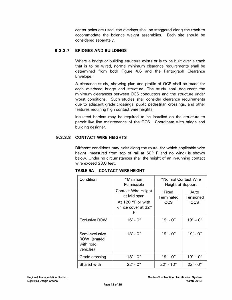
Regional Transportation District Section 9 – Traction Electrification System Light Rail Design Criteria March 2013
Page 13 of 36
center poles are used, the overlaps shall be staggered along the track to accommodate the balance weight assemblies. Each site should be considered separately.
9.3.3.7 BRIDGES AND BUILDINGS
Where a bridge or building structure exists or is to be built over a track that is to be wired, normal minimum clearance requirements shall be determined from both Figure 4.6 and the Pantograph Clearance Envelope.
A clearance study, showing plan and profile of OCS shall be made for each overhead bridge and structure. The study shall document the minimum clearances between OCS conductors and the structure under worst conditions. Such studies shall consider clearance requirements due to adjacent grade crossings, public pedestrian crossings, and other features requiring high contact wire heights.
Insulated barriers may be required to be installed on the structure to permit live line maintenance of the OCS. Coordinate with bridge and building designer.
9.3.3.8 CONTACT WIRE HEIGHTS
Different conditions may exist along the route, for which applicable wire height (measured from top of rail at 60° F and no wind) is shown below. Under no circumstances shall the height of an in-running contact wire exceed 23.0 feet.
TABLE 9A – CONTACT WIRE HEIGHT
Condition *Minimum Permissible
Contact Wire Height at Mid-span
At 120 °F or with ½” ice cover at 32°
F
*Normal Contact Wire Height at Support
Fixed Terminated
OCS
Auto Tensioned
OCS
Exclusive ROW 16’ - 0”
19’ - 0” 19’ – 0”
Semi-exclusive ROW (shared with road vehicles)
18’ - 0” 19’ - 0” 19’ - 0”
Grade crossing 18’ - 0” 19’ - 0” 19’ – 0”
Shared with 22’ - 0” 22’ - 10” 22’ - 0”

Regional Transportation District Section 9 – Traction Electrification System Light Rail Design Criteria March 2013
Page 14 of 36
railroad tracks
Maintenance Building**
18’ - 0” ** 19’ - 0” ** 18’ - 0”
Storage tracks 18’ - 0” 19’ - 0” 18’ - 0”
Under Structures***
15’-6”
* No allowance is made in the above table for future raising of the track.
** Less may be permitted with RTD approval.
*** Absolute minimum mid-span height under all conditions of temperature and ice loading, and including track tolerances. The contact wire height gradient limits will need to be adhered to for approach spans.
9.3.3.9 CONTACT WIRE GRADIENT
The pantograph shall track smoothly under the contact wire at all times. Where the contact wire height needs to be changed, the change shall not cause bouncing and arcing of the pantograph.
The following table provides AREMA’s recommendations for the maximum wire gradient versus LRV speed ranges. To allow for installation tolerances, the design wire gradient shall be not exceed 50% of those listed here:
Table 9B - maximum wire gradient versus LRV speed
LRV Speed Range (mph) As Built Maximum Gradient (%)
1-15 2.3
>15-30 1.3
>30-45 0.8
>45-55 0.6
9.3.3.10 CHANGE OF CONTACT WIRE GRADIENT
The maximum change of contact wire gradient shall be equal to one-half the maximum gradient, from one span to the next.
9.3.3.11 CONTACT WIRE REGISTRATIONS
The largest acceptable stagger at registrations shall be determined from basic engineering calculations in development of pantograph security.
Assemblies providing registration of the contact wire shall be designed to meet both the contact wire deviation criteria, along track movement

Regional Transportation District Section 9 – Traction Electrification System Light Rail Design Criteria March 2013
Page 15 of 36
and uplift where possible and the Maximum horizontal working load criteria.
The angle of contact wire deviation in the horizontal plane on a single steady arm contact wire clamp shall not exceed 7.5 degrees.
9.3.3.11.1 MAXIMUM WORKING LOADS
For the purpose of OCS Equipment design, the Maximum Working Load shall be defined as the worst case maximum load that may be applied to the specific piece of OCS equipment under Operating Condition and Non-Operating Condition. The designer shall apply and specify appropriate Factors of Safety relative to the worst cast Maximum Working Loads to ensure that the Ultimate capacity of the specific piece of equipment provides an adequate margin against failure
9.3.3.11.2 REGISTRATION ASSEMBLIES
Assemblies registering the contact wire shall be categorized and rated as listed below.
Light Load Push Off – 135 pounds Maximum Contact Wire Horizontal Working Load. This assembly is only to be applied where the design track speed is less than 40 miles per hour.
Light Load Pull Off – 350 pounds Maximum Contact Wire Horizontal Working Load
Medium Load Registration – 600 pounds Maximum Contact Wire Horizontal Working Load
Heavy Load Registration – 1200 pounds Maximum Contact Wire Horizontal Working Load. This application is typically serviced by two steady arms with contact wire swivel clamps installed 12 inches apart.
The Maximum Horizontal Working Load values for each category shall include combined radial load and wind load values determined using conductor tensions and wind forces calculated for both Operating Condition and Non-Operating Condition environments.
Each cantilever frame, as an assembled unit, shall be designed using its predicted applied Maximum Working Load values in conjunction with a proven structural design methodology (e.g. Load and Resistance Factor Design (LRFD), Allowable Stress Design (ASD), American Institute of Steel Construction (AISC),).
Mechanically loaded components, parts and sub assemblies shall be designed to provide the appropriate Factors of Safety for loads resulting from both Operating Conditions and Non-Operating Conditions. Factor
Regional Transportation District Section 9 – Traction Electrification System Light Rail Design Criteria March 2013
Page 16 of 36
of Safety values and conditions of use, are listed in Table 9C – Design Parameters.
9.3.3.11.3 TYPICAL LOADS
For the purposes of field inspections the following typical registration assembly maximum loads are anticipated under conditions where auto tensioned wiring balance weight equipment is not locked, or where fixed terminated wiring is at 60˚F, with no wind or ice present.
• Light Load Push Off – 80 pounds
• Light Load Pull Off – 200 pounds
• Medium Load Registration – 350 pounds
• Heavy Load Registration – 700 pounds
9.3.3.12 SECTIONING
The system sectioning shall be designed to enable the electrical protective relays to disconnect faulted sections of the distribution system, to permit planned maintenance, and to permit flexible operation during system emergencies.
Sectioning on the mainline shall be performed by means of insulated overlaps. Section insulators shall not be used in mainline tracks or crossovers used for normal train operations. Sectioning in crossovers and turnouts shall be performed by the use of insulated overlaps. Sectioning for emergency crossovers or turnouts, defined as crossovers or turnouts not used during normal revenue service, shall be performed using high-speed section insulators or insulated overlaps.
The primary connection and isolation of the system sections shall be performed by the substation DC feeder circuit breakers and by pad mounted disconnect switches which shall be located in substations sites.
To avoid contact wire damage insulated overlaps and section insulators shall not be located at the departing end in stations, on the approach to signals or any other places where trains will regularly stop and then, accelerate drawing power.
9.3.3.13 GROUNDING FOR STRAY CURRENT CORROSION CONTROL AND SAFETY
See Section 10.3.0.
9.3.3.14 GROUNDING FOR POLES AND GUY LOOPS
Grounding resistance for poles and guy foundation anchor loops shall be less than 25 ohms. Each shall have its own dedicated ground rod.
Regional Transportation District Section 9 – Traction Electrification System Light Rail Design Criteria March 2013
Page 17 of 36
Where poles are installed within a passenger station platform area, ground connections shall be made to the station grounding grid. (See section 9.7.1.17).
9.3.3.15 GROUNDING FOR OCS SUPPORTS UNDER BRIDGES AND ON WALLS
All OCS supports under bridges, building or mounted on retaining walls shall be grounded with a resistance to ground of less than 25 ohms or isolated from the supporting structure by using a third level of insulation. Multiple adjacent supports may be connected to each grounding system. Grounded components shall be a minimum of 4 feet from any live component (e.g. messenger wires and contact wires), or otherwise be provided with an insulated cover.
9.3.3.16 GROUNDING FOR SURGE ARRESTERS
All surge arresters shall be grounded via an independent ground cable directly attached to a grounding device such as ground rod(s) or ground mat with a ground resistance of less the 5 ohms. Pole grounds shall be connected to surge arrester grounding devices.
9.4 STANDARDS AND CODES
All design work and material selection shall conform to or exceed the requirements of the latest editions of standards and codes issued by the following organizations:
• Association of American Railroads (AAR)
• American Railway Engineering and Maintenance of Way Association (AREMA)
• American National Standards Institute (ANSI)
• American Society for Testing & Materials (ASTM)
• Institute of Electrical & Electronics Engineers (IEEE)
• National Electrical Manufacturers Association (NEMA)
• Insulated Cable Engineers Association (ICEA)
• International Building Code (IBC)
• American Society of Mechanical Engineers (ASME)
• Underwriters Laboratories (UL)
• National Fire Protection Association (NFPA)
• National Electrical Testing Association (NETA)
• National Electrical Code (NEC), where applicable
• National Electrical Safety Code (NESC) – (latest edition mandated by the CODE OF COLORADO REGULATIONS (CCR) 723-7)
• Applicable State, Local, and County Codes
9.5 PRODUCT REQUIREMENTS
9.5.1 TRACTION POWER SUPPLY SYSTEM

Regional Transportation District Section 9 – Traction Electrification System Light Rail Design Criteria March 2013
Page 18 of 36
9.5.1.1 EQUIPMENT DESCRIPTION
The traction power supply system shall consist of all equipment between the interface points with the power utility, the distribution system and negative return impedance bonds. The equipment includes AC cables, AC switchgear assemblies, transformer/rectifier units, DC switchgear assemblies, busbars, positive and negative cables, cable ductbanks, conduits and raceways, negative return and drainage assemblies, substation housings, foundations, grounding systems, protective systems, auxiliary power supply systems, HVAC systems, batteries and chargers, fire and intrusion systems, lightning arresters, annunciation and control systems, metering equipment, supervisory control equipment, portable fire extinguishers, circuit breaker test cabinet, special tools for maintenance, operating and maintenance manuals and training of RTD personnel.
The electrical equipment shall be housed in traction power substations which shall be of the package type, except where conditions do not permit. Each package substation shall be factory pre-wired, assembled and tested and housed in a self supporting, transportable enclosure suitable for outdoor installation. Each package substation shall be a completely self-contained and integrated unit installed on the previously prepared foundation designed to accommodate a 30 - inch crawl space and connected via suitable feeder cables to the utility interface point and to the traction power distribution and return systems. Where substations cannot be provided as packaged units, equipment shall be individually installed and tested in separately constructed buildings or rooms.
Entry doors shall be provided. The entry doors shall be of sufficient size for installation or removal of any piece of equipment if no other access is provided. All equipment shall be designed and arranged such that all repair, maintenance and cable connections can be accomplished from within the substation enclosure or through access panels at the rear of equipment lineups.
9.5.1.2 INCOMING AC FEEDERS
The incoming substation service shall be by underground cables. Cable ductbanks, conduits, raceways and manholes inside the substation property line shall be designed from the point of utility interface to the traction power substation. The design shall be fully coordinated with the utility requirements and interfaced with the utility overhead or underground facilities. The feeder rating shall permit the substations to supply the specified load cycle and short circuits without exceeding the allowable equipment temperatures.
9.5.1.3 AC SWITCHGEAR
The AC switchgear assembly shall provide the means to deliver, control and measure the substation power requirements. The assembly shall be
Regional Transportation District Section 9 – Traction Electrification System Light Rail Design Criteria March 2013
Page 19 of 36
housed in dead-front enclosures containing AC disconnect switch, AC circuit breaker, metering equipment and auxiliary power supply.
The equipment shall conform to ANSI C37.20.2 ”IEEE Standard for Metal Clad and Station Type Cubicle Switchgear”, and shall be UL listed and labeled, or certified by an independent testing laboratory to meet ANSI and UL standards. Working space, complying with NEC Article 110”, shall be provided to gain access to components from the front and the rear of the switchgear. Incoming high-voltage switch sections may be metal-enclosed conforming to C37.20.3, “IEEE Standard for metal-enclosed interrupter switchgear”.
9.5.1.4 RECTIFIER TRANSFORMER
The rectifier transformer shall be 12 pulse, self-cooled, with primary voltage to be consistent with utility supply, and equipped with appropriate taps.
The transformer/rectifier shall be designed so that the maximum overall regulation rate is not greater than 6% ± 0.5% between 1% rated load and 450% rated load.
The transformer/rectifier design and component selection shall minimize harmonic distortion and shall comply with IEEE 519.
9.5.1.5 RECTIFIER
The rectifier shall be silicon diode type, natural convection-cooled. Thyristor rectifiers will be considered where necessary to provide improved voltage regulation or reduce overall traction electrification costs. The rectifier shall be a complete operative assembly consisting of the diodes, heat sinks, internal buses, connections, diode fuses and all other necessary components and accessories. It shall consist of full-wave bridges providing 12-pulse rectification.
The rectifier shall be capable of withstanding the duty cycles specified in Section 9.3.1.5 without exceeding the manufacturer’s allowable diode junction temperature and without damage to any component:
The rectifier shall also be capable of withstanding the maximum theoretical short circuit current on the rectifier until cleared by the fault clearing devices.
9.5.1.6 DC SWITCHGEAR ASSEMBLY
The DC switchgear assembly shall consist of the positive and negative switches, rectifier, bus work, and DC circuit breakers. It shall form a lineup of dead-front metal-clad or metal-enclosed switchgear built to ANSI C37.20.2 “IEEE Standard for Metal Clad and Station Type Cubicle Switchgear”, or to ANSI C37.20.3 “IEEE Standard for Metal Enclosed Switchgear”. The DC circuit breakers shall be high-speed, stored energy, draw-out, single-pole units, with bottom feeder cable entry. DC circuit breaker switchgear cubicles shall conform to C37.20.1, “IEEE standard for metal-enclosed low-voltage power circuit-breaker switchgear”.

Regional Transportation District Section 9 – Traction Electrification System Light Rail Design Criteria March 2013
Page 20 of 36
9.5.1.7 NEGATIVE RETURN AND SYSTEM
The negative return assembly shall include negative disconnect switches, negative busbar, terminations for negative return cables and other associated equipment. All equipment shall be rated at the system maximum rated voltage.
9.5.1.8 PROGRAMMABLE LOGIC CONTROLLER (PLC)
This section sets forth the minimum acceptable requirements for a Programmable Logic Controller (PLC) and associated modules as described below for the specified control, processing, and monitoring system and to interface with the Traction Power Substation equipment and the SCADA System. The Contractor shall be required to provide a full featured, integrated, modular operational PLC system. The modules shall be capable of being inserted at the site, with no factory re-wiring required.
Contractor shall provide a Programmable Logic Controller (PLC) relay interface system. All functional requirements specified shall be met or be exceeded by the PLC system. PLCs, associated network and interfaces shall be rated to utility standards for substation environment.
At a minimum, the PLC system shall consist of the following components:
• Electronic terminators shall replace the normal auxiliary and interposing relays. These shall be placed at the A/C switchgear cubicle, rectifier unit, rectifier DC disconnect switch unit, at each DC feeder circuit breaker unit and at each remote DC disconnect switch group.
• A stand alone modular programmable controller, or protective relay, shall be designed to provide the breaker reclosure relay, long time overload relay, frame fault protection relaying and lockout relays. Running rail voltage monitoring shall be furnished at each DC feeder breaker.
• “Transfer tripping" of DC breakers adjacent to the section where a fault is detected will be provided by an optical fiber link and associated interface equipment.
• A local area network providing communication from the feeder breakers modular programmable controllers to the substation master programmable controller shall be furnished.
• A master PLC designed and programmed to integrate and control all interpanel connections and to provide substation monitoring and data logging shall be furnished at each traction power substation. The master PLC in combination with the above-described local area network shall result in the elimination of majority of the inter-panel wiring where applicable.
Regional Transportation District Section 9 – Traction Electrification System Light Rail Design Criteria March 2013
Page 21 of 36
• A man/machine interface (operator panel) capable of providing substation status annunciation and local/remote control of substation operations (e.g. opening and closing of circuit breakers) shall be furnished at each traction power substation.
The PLC system and equipment shall be designed to operate in the environment and conditions specified by the requirements of the LRT system. All electrical interfaces, including relaying, voice and data, shall meet ANSI/IEEE surge withstand requirements. The system shall be immune to Radio Frequency Interference and shall be designed to meet the requirements of ANSI/IEEE C37.90.2. The presence of transients on the communication interfaces shall not cause misoperation or blocking of any of critical communications. The system shall be failsafe.
The systems shall also be capable of integrating with the SCADA system using Ethernet for communication. A SCADA points list will be developed with RTD staff that includes alarms, status and supervisory control functions. Alarms will consist of all locally annunciated alarm points discussed in 9.5.1.9. Status points will consist of circuit breaker position, and other necessary points selected to give information about the condition of the remote station to Operations Control Center. The selection of a “local” control mode at the substation shall inhibit remote SCADA control of specific functions, but shall not prevent the monitoring of all substation parameters via the SCADA system.
9.5.1.9 LOCAL ANNUNCIATION
The substations shall be equipped with an internal annunciation system. The annunciator shall be of modular design, programmable and may be integrated with the PLC described in 9.5.1.8, if provided. The annunciator shall consist of a touch screen panel with indication, audible alarm, test, silence, acknowledge and reset functions, as well as other associated equipment.
A flashing blue light shall be installed on the exterior of the substation, visible from the LRT trackway. The blue light shall be illuminated whenever a DC breaker is open or the DC output is not available.
An electrical alarm "points list" shall be developed listing electrical alarms to be annunciated. These alarms will be annunciated locally and by the blue light which shall be visible from the trackway.
9.5.1.10 AUXILIARY POWER
Each substation shall be furnished with AC and DC distribution panel boards. The AC panel board shall supply the substation lighting, HVAC, convenience receptacles and battery charger. The DC panel board shall supply circuit breaker and other control power and annunciation.
9.5.1.11 BUSBARS AND BUS CONNECTORS
Busbars and bus connections shall be designed to withstand, without damage to the bus or enclosure, the thermal and mechanical stresses

Regional Transportation District Section 9 – Traction Electrification System Light Rail Design Criteria March 2013
Page 22 of 36
occurring during the specified load cycle and the rated short circuit currents.
Busbars shall be made of rigid high electrical conductivity copper and shall be adequately insulated and braced with high strength insulators. Bus connections shall be bolted and furnished with silver-plated surfaces. Each joint shall have conductivity at least equal to that of the busbar.
9.5.1.12 EQUIPMENT ARRANGEMENT
Substations shall have adequate area to accommodate all the electrical equipment and ancillary components. Relative spacing and positioning of each item of equipment shall permit maintenance, removal and replacement of any unit without the necessity of moving other units. The arrangements of the equipment shall permit doors to be opened, panels to be removed, and switchgear to be withdrawn without interference to other units. Ceiling heights and structural openings shall permit entry and removal of the largest components installed in the housing.
Wall space for future growth will be provided. Minimum working clearances will be provided per the NEC. A minimum of 6 feet of space in front of high voltage switchgear shall be provided. Two exit doors with panic hardware, one from each end of the switchgear, shall be provided.
9.5.1.13 GROUNDING
Each traction power substation shall be furnished with a ground mat and provisions for equipment grounding. The ground mat shall be contained within the substation property lines and shall be designed so that the step and touch potentials at the rated short circuit current do not exceed the recommended safety limits of IEEE Standard 80. All grounding connections shall be capable of carrying the rated short circuit current.
Substation high voltage DC equipment enclosures shall be low resistance grounded.
9.5.1.14 NEGATIVE RETURN SYSTEM
The substation negative bus shall be connected to the running rails. The rails shall be welded in continuous lengths. Any bolted rail joints shall be electrically bonded. At locations requiring insulated rail joints, the continuity of the negative circuit shall be maintained by the use of impedance bonds.
In areas of double track equipped with double-rail AC track circuits, cross bonding between tracks for negative return equalization shall be accomplished by impedance bond center tap connections at each substation return connection location. In areas of double track equipped with single rail AC track circuits, cross bonding between tracks shall be accomplished by direct connections between the negative traction
Regional Transportation District Section 9 – Traction Electrification System Light Rail Design Criteria March 2013
Page 23 of 36
return rails only. Single rail negative return segments shall not exceed 60 feet in length. In areas of trackage not equipped with track circuits, cross bonding between tracks shall be provided throughout the system, with a spacing of cross bonds of 1000 feet or at every second tracks circuit boundary.
9.5.1.15 OPERATIONS FACILITY ELECTRIFICATION
See Section 11.
9.5.2 OVERHEAD CONTACT SYSTEM (OCS)
9.5.2.1 EQUIPMENT DESCRIPTION
The OCS consists of all equipment between the interface with the DC traction power supply equipment and the vehicle pantograph. The equipment shall include foundations, poles, cantilevers, bridge arms, shop building supports, system conductors, feeders, hangers, jumpers, terminations, tensioning devices, sectioning equipment and all other necessary equipment.
The overhead system shall be designed to be environmentally acceptable. Within the mechanical and structural design constraints, the system structures and associated equipment shall be as lightweight as possible and shall use visually unobtrusive fittings. The system shall be double-insulated with each level of insulation compatible with the system insulation class.
A minimum of 4 foot separation between energized components and grounded structures shall be provided.
In areas where the grade separation or other means may allow the public to be in close proximity to the OCS, at least 10 feet separation and a physical barrier shall be provided to prevent access to any energized component. In cases where any energized component is less than 10 feet separation from the edge of the ROW, a solid barrier or panel must be placed between the energized component to prevent access to the energized component.
9.5.2.2 FOUNDATIONS
The design of foundations for supporting structures and guy anchors shall be based on the structure loading calculations and soil data, also refer to Section 6, Structural Design. The supporting structure foundations shall be designed to accept bolted base poles and structure grounding. Foundations for tubular poles with feeder cables, shall have provision for feeder conduits.
The size and placement of the OCS foundation anchor bolts shall be in accordance with RTD’s previously installed OCS foundation designs. Foundation elevations in the station area shall be coordinated with the station design. Deviation from the standard plans requires prior approval from RTD.

Regional Transportation District Section 9 – Traction Electrification System Light Rail Design Criteria March 2013
Page 24 of 36
9.5.2.3 POLES AND SUPPORTING HARDWARE
All poles shall be designed as free standing with the exception of termination poles for auto tensioned catenary may use guy foundations in non-public areas. All poles shall have a base plate drilled to fit the foundation bolt pattern and shall have provision for attaching grounding or bonding conductors. Pole base plates shall be designed and drilled to prevent a high strength type of pole being inadvertently erected onto a foundation designed for a weaker pole or column. Pole designs shall be consistent with RTDs existing poles.
For open track, the poles shall be galvanized wide flange beams mounted between the tracks except where special conditions require side poles. For operations in paved track where aesthetics are important, tapered tubular steel poles will be used.
Poles shall be designed so that the normal operating across-track live load deflection at contact wire height shall not exceed 1 inch.
Poles shall be designed to deflect no more than 2.5% of their length when rated maximum bending load is applied two feet from the top of pole.
9.5.2.4 CANTILEVERS
The cantilevers shall be designed for a range of loads, range of pole offsets, and for a range of system heights considering the system installation tolerances. The cantilever members shall be designed for easy installation and adjustment.
With the exception of contact wire clamp components, cantilever assemblies shall be configured to be clear of the pantograph clearance envelope at all times.
9.5.2.5 BRIDGE AND SHOP BUILDING SUPPORTS
Bridge supports and shop building supports shall be used where sufficient clearance to accommodate a cantilever-type assembly is not available. The supports shall be designed to restrict the uplift of the contact wire when subjected to pantograph pressure and shall be capable of providing vertical and across-track adjustment. The bridge supports shall permit the longitudinal movement of contact wire.
9.5.2.6 INSULATORS
Insulators shall provide electrical insulation in accordance with the system insulation class and shall have the mechanical safety factors specified.
The insulators shall have resistance against deterioration from exposure to sunlight and airborne chemical pollution including magnesium chloride. The insulators shall be a light gray, sky tone color and their life expectancy shall be compatible with that of the rest of the equipment.
Polyester resin strain insulators shall not be used.

Regional Transportation District Section 9 – Traction Electrification System Light Rail Design Criteria March 2013
Page 25 of 36
9.5.2.7 CONDUCTORS AND ASSOCIATED ITEMS
Contact wire shall be 350 kcmil solid, grooved(ASTM B47), hard-drawn copper conductor with an identification groove in the top lobe of the wire. The messenger wire shall be stranded, hard-drawn copper conductor. All feeder and connecting cables shall be insulated, stranded copper conductors with sufficient flexibility to prevent fatigue failure of the cable due to vibration of the overhead conductors.
All conductor connections, attachments and clamps shall use copper or bronze fittings and shall be designed for ease of replacement and maintenance.
Continuity and equalizing jumpers shall be flexible copper conductors. The spacing of the jumpers shall be determined based on the required current conductivity. However, a minimum of one jumper per span shall be used. In addition to the jumpers, current carrying hangers of stranded copper wire can be used. All conductive copper or bronze hardware to terminal and hardware to wire connections shall be coated with grease on the mating surface.
Catenary hangers shall be insulated if not designed to carry current.
9.5.2.8 TERMINATIONS AND MIDPOINT ANCHORS
Strain-type termination assemblies shall be light weight. Wire wrap, straight line, cone or wedge type designs are acceptable. Turnbuckles shall be included as appropriate and shall have adequate adjustability after installation.
A mid-point anchor arrangement shall be used at or near the mid-point of each tension length of auto-tensioned equipment.
9.5.2.9 TENSIONING DEVICES
The auto-tensioned system conductors shall be tensioned using cast iron or steel balance weights. At wide flange beam poles, the balance weights shall be positioned in the pole web to be as unobtrusive as possible. The poles with balance weights shall be fitted with guides that will prevent the balance weight from binding or jamming over the entire range of movement. The weight shall be engaged by two guides at all times. The guide shall prevent the weights from falling away from the pole during a broken wire condition. In areas frequented by passengers or pedestrians, the balance weights shall be provided with a protective shield. The tensioning devices shall accommodate conductor expansion and contraction due to temperature change, and long term creep of the wire. All operating cables shall be of flexible stainless steel wire.
Spring tensioning devices may be used for short tension lengths such as at crossovers with site specific approval of RTD.
Pneumatic or hydraulic tensioning devices shall not be used.
9.5.2.10 SECTIONING EQUIPMENT
Regional Transportation District Section 9 – Traction Electrification System Light Rail Design Criteria March 2013
Page 26 of 36
Section Insulators shall not be installed in mainlines or crossovers in regular revenue service. High-speed section insulators may be used in emergency crossovers and in yards. Section insulators without skids shall be installed in the yards, except for test tracks.
No load disconnect switches shall be used to electrically connect and disconnect line sections. The disconnect switches shall be rated to withstand the system worst-case overload and short circuit conditions without overheating.
9.5.2.11 SURGE ARRESTERS
Over-voltage and lightning protection for the OCS shall be provided by surge arresters. The arresters shall be rated to withstand the maximum system voltage and anticipated voltages induced from any paralleling high-voltage transmission lines onto the system conductors. The arresters shall be capable of discharging the energy resulting from lightning strikes to the system.
All feeder riser cables and both sides of disconnect switches between power sections shall be protected by lightning arresters. Arrester design and installation shall prevent grounding of the energized circuit during catastrophic failure.
At a minimum, arresters shall be located adjacent to each substation and in all areas of reduced clearances, such as at overhead bridges or buildings, high points in the alignment such as flyovers, at the end of track and each side of mid section disconnect switches. Additionally, surge arresters shall be located at a maximum of 1000 feet apart.
9.5.2.12 PROTECTIVE SCREENING
When the LRT is constructed below a bridge, building, or structure, screening and fencing shall be erected to physically separate the catenary wires from human reach. Furthermore, the overpass screening and/or fencing shall be constructed to protect LRVs from vandals dropping objects from above. The design of the overpass screening and/or fencing shall be compatible with the local architecture and landscaping. All fencing passing over the LRT shall be grounded. Fence grounding resistance shall be less than 25 ohms.
Regional Transportation District Section 9 – Traction Electrification System Light Rail Design Criteria March 2013
Page 27 of 36
9.6 DESIGN PARAMETERS
TABLE 9C – DESIGN PARAMETERS
Climatic Conditions
Maximum Ambient Temperature: 100˚F
Minimum Ambient Temperature: -25˚F
Radial Ice Loading: Non-operating conditions 1/2 in. on contact and messenger wires
Radial Ice Loading: Operating Conditions 1/2 in on messenger wire ¼ in on contact wire
Maximum Wind Speed:
Structural design 90 mph to 116 mph as required by local codes
Pantograph Security design 55 mph
OCS Conductor Sizes and Material
Messenger Wire: Copper. Alternative sizes require RTD approval
500 KCMIL HD
Contact Wire: 350 KCMIL HD copper unless directed by RTD
Factors of Safety -- Conductors and Wires
Operating: 2.0
Non-operating: 1.6
Contact Wire Wear for Mechanical Design 30%
Factors of Safety – Strain Insulators
Operating: 4.0
Non-operating: 3.2
Factors of Safety -- Hardware
Operating: 2.5
Non-operating: 2.0
Minimum Electrical Clearances
Static Clearance: 4 in
Passing Clearance: 3 in
Contact Wire Heights Above Top-of-Rail See Section 9.3.3.8. RTD approval is required for any deviation in the minimum contact wire height (e.g. tunnels and overpasses)
Maximum Contact Wire Gradients
Regional Transportation District Section 9 – Traction Electrification System Light Rail Design Criteria March 2013
Page 28 of 36
Constant Gradient: See Section 9.3.3.9
Gradient Change: See Section 9.3.3.10
Pantograph Security
Minimum Pantograph Security: 6 in. horizontal from tip of horn
Track maintenance Tolerances
Ballast Track
Alignment: 1 in
Cross level: 1 in
Embedded Track
Alignment: 0.5 in
Cross level: 0.5 in
Track Gauge
Widening: 0.625 in
Vehicle Data
Maximum Roll (broken springs) 4%
Pantograph Data See Section 13.2.1.2
Maximum Wire Height anywhere in a span. 23.00 ft
9.7 CONDUIT AND DUCTBANKS
The following parts apply to all conduit and ductbanks for traction power, signals, communications and high voltage (15 KV) AC.
9.7.1 RACEWAY AND DUCTBANK SYSTEM
This section describes the design criteria necessary to provide raceway and ductbank systems to protect all power wiring and system cables on RTD’s LRT facilities. The system wide electrical raceway and ductbank system includes conduits, ductbanks, cable trays and cable trough installations and related manhole, handhole and pullbox equipment. Generally there are two ductbank systems used within the trackway, parallel to the mainline track, namely the signal/communication (SC) mainline ductbank, and the traction electrification (TE) ductbank in addition there are various lateral ductbanks.
9.7.1.1 SCOPE
System wide Electrical Raceway and Ductbank System applies to all traction electrification systems, communication systems, signal systems, fare collection equipment and electrical facilities including system buildings and rooms, maintenance facilities, passenger station platforms, park and ride lots, parking structures, lighting systems, pedestrian and LRT bridges, and AC low voltage and high voltage electrical systems.

Regional Transportation District Section 9 – Traction Electrification System Light Rail Design Criteria March 2013
Page 29 of 36
9.7.1.2 SYSTEM INTERFACES
System wide Electrical Raceway and Ductbank System engineering shall be coordinated with the other disciplines, including architectural, mechanical, utility, electrical, civil, structural, trackwork, electrification, signal and communication designs.
9.7.1.3 CODES AND STANDARDS
Raceway and ductbanks design shall conform to the latest edition of the following codes where applicable:
• National Electrical Code (NEC)
• National Electrical Safety Code (ANSI/IEEE C.2)
• Electrical Codes or amendments of the local authority having jurisdiction
• American National Standards Institute (ANSI)
• National Electrical Manufactures Association (NEMA)
• Institute of Electrical and Electronics Engineers (IEEE)
• National Fire Protection Association (NFPA 70, 101 & 130)
• The Occupational Safety and Health Act (OSHA)
9.7.1.4 PRODUCTS
Raceway products used shall in all cases be listed and labeled by a nationally recognized electrical safety testing organization.
9.7.1.5 FUNCTIONAL REQUIREMENTS
All power wire and systems cables shall be protected by conduit, cable tray, or cable trough per this section, except for low voltage signal or communication wiring where protected from physical damage within traction electrification facilities, signal or communication buildings and rooms, bungalows, or cases. Installations shall comply with the NEC and local county and city codes.
Spare raceway capacity of 40% minimum shall be provided in the mainline SC ductbank, TE, HV, and lateral ductbanks or conduit runs including station platforms, except where determined by RTD. Spare capacity shall be defined as the remaining useable capacity within a raceway in conjunction with N.E.C. requirements. Spare cable tray or cable trough capacity shall be provided in all installations for future equipment. RTD may determine that the spare capacity is not necessary at various locations; due to the expense that would be incurred and this requirement could be reduced in capacity or eliminated.
Manholes shall be provided in the mainline SC ductbank, in TE ductbanks, in HV ductbanks, in lateral ductbanks, and in conduit runs at junction points and for cable pulling requirements in the cable system. Handholes shall be provided in various lateral

Regional Transportation District Section 9 – Traction Electrification System Light Rail Design Criteria March 2013
Page 30 of 36
ductbanks or conduit runs at junction points and for cable pulling requirements in the cable system. On LRT bridges, tunnels, or shafts where raceways are provided pullboxes shall be provided.
9.7.1.6 RACEWAY PRODUCTS
Raceways may be galvanized rigid steel conduit (GRSC), PVC Schedule 40 conduit, PVC Schedule 80 conduit; HDPE conduit, HDPE micro-duct conduit, PVC coated galvanized rigid steel conduit (PVC/GRSC), rigid non-metallic fiberglass reinforced epoxy conduit, electrical metallic tubing (EMT), liquid-tight flexible metal conduit or flexible metal conduit.
Cable trays shall be aluminum, fiberglass-reinforced plastic, welded or swaged steel hot-dipped galvanized after fabrication, ladder type with formed rungs and channel type side rails with inward or outward turned flanges. Special design circumstances may require physical protection of the cables, and solid or ventilated cable trays and covers may be used.
Cable trough and cover shall be a dielectric material, High Density Polymer Concrete, pre-fabricated, nonmetallic, rated for exterior below grade use, resistant to sunlight exposure and suitable for use in wet locations. Individual cable trough sections must interlock together to make a continuous cable trough without gaps. Covers shall sit inside the trough, be flush with the finished grade, be designed to withstand excessive loading and not shatter and be secured with stainless steel vandal proof hardware. The weight of each cover shall not exceed the allowable handling weight as per OSHA requirements.
9.7.1.7 SYSTEM WIDE DUCTBANKS
Mainline ductbanks shall be schedule 40 PVC conduit, Multi-celled Schedule 40 PVC conduit, HDPE conduit, or Multi-celled Micro-duct conduit, concrete encased in Controlled Density Fill concrete (CDF). Signal/Communication Lateral Ductbanks shall be Schedule 40 PVC conduit, with GRSC or PVC/GRSC conduit elbow, or Schedule 40 PVC conduit large radius elbows greater than 6 feet encased in 1500 psi concrete. Traction electrification (TE) ductbanks initiating from facilities to the first manhole outside of the alignment shall be Schedule 40 PVC conduit, with GRSC or PVC/GRSC conduit elbows, or PVC Schedule 40 elbows with a radius greater than 6 foot encased in red 2500 psi steel re-enforced concrete. TE Ductbanks initiating from the first manhole outside of the alignment to all subsequent manholes and feeder poles within the alignment shall be Schedule 40 PVC conduit, with GRSC or PVC/GRSC conduit elbows, or PVC Schedule 40 elbows with a radius greater than 6 foot encased in red 2500 psi concrete. Ductbanks with reinforced steel rebar are used for special utility and roadway crossings. The exact ductbank dimensions vary with the number and size of conduits. Plastic spacers shall be provided between conduits to allow for concrete–encasement around the conduits. The minimum spacing between conduits is 1.5 inches for signal/communication conduits and 3

Regional Transportation District Section 9 – Traction Electrification System Light Rail Design Criteria March 2013
Page 31 of 36
inches for traction electrification and power conduits unless otherwise required by the NEC. The overall concrete-encasement around the outside conduits shall be 3 inches on all sides. Trench walls that are stable may provide the forms for the concrete encasement.
Ductbanks shall be located longitudinally along the length of the trackway and between the mainline tracks. Generally the ductbank is located below the end of the track ties at a depth of 36 inches so that conflict with OCS and signal foundations is avoided and the ductbank runs in a straight line between conduit transitions into manholes. If required, due to special circumstances, ductbanks located other than between the mainline tracks will be determined solely at the discretion of RTD. Ductbanks are to be set on a prepared and compacted bed.
When it is necessary, lateral ductbank crossings below the track are permitted as long as the ductbank meets the minimum depth requirements.
Where obstacles such as underground utilities or foundations are encountered the ductbank shall be gradually offset around them and must meet the concrete-encasement and conduit bending requirements.
Ductbanks shall be located precisely on all plans and design drawings. Ductbanks shall be sloped to drain to manholes or handholes, be located to avoid interference with new or existing utilities, and be located at a minimum depth of 36 inches below finished grade. Where shallow manholes are utilized, minimum depth of ductbank shall be 30 inches as it enters the manhole. Conduits shall be limited to a maximum of 270˚ of bend between manholes, handholds, junction boxes, or termination points.
All ductbanks shall have a trace wire installed along the entire length; initiating from a manhole and terminating at the ductbanks end. Trace wires installed within a manhole shall be terminated within an appropriately rated enclosure, on a terminal strip and identified with its corresponding ductbank number.
9.7.1.8 SYSTEM WIDE RACEWAYS
CONDUIT
Within the trackway, raceways may be direct buried and shall be PVC/GRSC conduits if designs are encountered where concrete encasement cannot be achieved due to space restrictions.
The final signal raceway connections (normally the last 10 feet of the conduit run from signal handhole or into bungalows and cases) to signal equipment maybe direct buried and shall be schedule 40 PVC conduit.
On LRT bridges, exposed raceways for signal, communication, traction electrification, and lighting shall be galvanized rigid steel conduit or rigid non-metallic fiberglass reinforced epoxy conduit and its use will be determined solely at the discretion of RTD. If raceways are concealed
Regional Transportation District Section 9 – Traction Electrification System Light Rail Design Criteria March 2013
Page 32 of 36
as an integral part of an emergency pedestrian walkway schedule 40 PVC conduit may be used, except for transitions at the end of the bridge, which shall be PVC/GRSC conduit direct buried or ductbank with GRSC conduit. Transitions at end of bridges require expansion couplings.
Cable Tray
The use of cable trays is restricted to use within system buildings, across pedestrian bridges and rooms. Cable trays and supports shall be designed to provide adequate strength to support the weight of the tray, cables, and future cables and meet the local seismic requirements. The use of fiberglass cable trays is generally used inside TP Substations for DC feeders and cables.
Cable Trough
The use of cable trough is restricted to existing trackways and its use will be determined solely at the discretion and approval of RTD. If required, due to special circumstances, cast-in-place type cable troughs may be located on LRT bridges as an integral part of an emergency pedestrian walkway as determined solely at the discretion and approval of RTD. Covers for cast-in-place cable troughs shall be pre-fabricated High Density Polymer Concrete and be secured with stainless steel vandal proof hardware. The capacity of the approved cable trough shall be 200% of the feeding conduit system.
Cable trough may be used for signal, signal power and communication cables only. The cable trough shall have integral dividers to maintain separation between signal, signal power and communication cables. Cables shall only enter or exit the cable trough through cable trough handholes or pullboxes that are an integral part of the cable trough system.
The cable trough shall be located longitudinally along the length of the trackway and shall not be located between mainline tracks. Cable troughs shall not be located directly above longitudinal runs of track drains or other utilities. Where obstacles, such as OCS and signal foundations, or utility manholes are encountered, the cable trough shall be gradually offset around the structure. Cable trough shall be placed in a level trench, with the lids flush with finished grade.
Cable troughs shall not be used in station platform areas, road and pedestrian crossings, high rail accesses and any areas accessible to pedestrians.
9.7.1.9 MANHOLES, HANDHOLES AND PULLBOXES
Manholes shall be of the pre-cast concrete type complete with cable supports, pulling irons, and a ground rod, and all metallic parts shall be internally grounded. Manholes or handholes installed in streets shall be equipped with a cast iron cover and grade ring suitable for HS20 street
Regional Transportation District Section 9 – Traction Electrification System Light Rail Design Criteria March 2013
Page 33 of 36
loading and which can be adjusted for final grade. In other locations, manhole covers shall be torsion assisted hot-dipped galvanized steel diamond plate suitable for HS20 street loading and handhole covers shall be hot-dipped galvanized steel diamond plate suitable for HS20 street loading.
Handholes shall be of the pre-cast concrete or polymer complete type. Pre-cast concrete handhole covers shall be hot-dipped galvanized steel diamond plate suitable for HS20street loading. Polymer handholes shall have a minimum ANS/SCTE 77 rating of Tier 15 and polymer covers suitable for HS20 street loading.
Pullboxes shall be welded hot-dipped galvanized steel boxes or cast-in-place boxes with hot-dipped galvanized steel diamond plate covers, for use on LRT bridges, in tunnels and in shafts. All manholes, handholes and pull boxes shall be identified with welded raised lettering, except platform handholes, which shall be cast integral with the cover. All manholes, handholes and pullboxes, and junction box covers shall be traffic rated.
9.7.1.10 HIGH VOLTAGE RACEWAYS AND DUCTBANKS
High voltage raceways and HV ductbanks that are maintained by RTD, and are used for AC feeders (greater than 600V) shall be GRSC, PVC/GRSC, or PVC conduits encased with red 2500 psi concrete, and the conductors separated from other systems per the NEC.
If required because of electromagnetic interference (EMI) high voltage AC conductors shall be installed in galvanized rigid steel conduit or other means shall be taken to mitigate the effects of the EMI.
High voltage AC conduits shall have a bending radius no less than 36 inches.
9.7.1.11 UTILITY RACEWAYS AND DUCTBANKS
Utility raceway and ductbank installations shall meet the construction and material requirements of the local utility if installed under an RTD contract.
9.7.1.12 STATION PLATFORMS
For station platform, raceways shall be schedule 40 PVC conduits embedded in fill and located at a minimum depth of 18 inches below the finished grade of the platform slab. All conduit stub-ups through the platform slab or foundations shall be PVC/GRSC conduit. Platform handholes shall be located along the platform, generally towards each end and in the middle of the platform to provide junction points for the communication cables and power wiring. Handholes and covers shall be pre-cast high density polymer concrete type with split covers if used for communication cables and power wiring and the box sections shall be divided. For all mainline platform conduit penetrations into the handholes, that run the length of the platform, they shall enter the side
Regional Transportation District Section 9 – Traction Electrification System Light Rail Design Criteria March 2013
Page 34 of 36
of the pullbox and be provided with bell ends. All lateral conduit penetrations into handholes shall enter the bottom of the handhole and be provided with bell ends.
Communication conduits shall be provided to all planned and future communication equipment on the station platforms. Spare conduits shall be provided to all mainline conduit runs along the length of the platform, and to all shelters including future shelters. All exposed conduits shall be painted to match the structure which to it is attached.
All conduits shall be installed flush with top of platform and the conduit for future use shall be capped and flush with top of platform.
9.7.1.13 PARK-N-RIDE LOTS AND STREET LIGHTING
For park and ride lot lighting and street lighting systems that are maintained by RTD, raceways shall be schedule 40 PVC conduit, and direct buried 30 inches minimum below grade. Raceways buried less than 30 inches below grade shall be concrete encased.
Communication conduits and handholes shall be provided to all planned and future communication equipment at the park and ride lots. Handhole requirements are the same as listed for station platforms.
For all street lighting systems not maintained by RTD, but installed under an RTD contract, the raceways shall meet the construction and material requirements of the local authority having jurisdiction.
9.7.1.14 PEDESTRIAN BRIDGES
For pedestrian bridges, raceways for signal, communication, traction electrification, and lighting conduits shall be GRSC conduits, PVC/GRSC conduits, or rigid non-metallic fiberglass reinforced epoxy conduit if exposed or concealed.
9.7.1.15 MAINTENANCE FACILITIES
For maintenance facilities, interior installations of raceways shall be EMT, GRSC, or flexible metal conduits at dry locations not subject to damage; GRSC conduits at dry locations subject to damage; and PVC/GRSC or liquid tight flexible metal conduits at wet or damp locations. All exterior installations of raceways shall be GRSC, PVC/GRSC, or liquid tight flexible metal conduits. All raceway installations under-slabs or in-slabs of structures shall be GRSC, PVC/GRSC or PVC conduit, and all conduit stub-ups through the building slab or foundations shall be PVC/GRSC conduit.
For the yard and site areas of maintenance facilities, ductbanks with manholes and handholes shall be provided, see the system wide ductbanks section for requirements. All street or yard lighting system raceways within the track areas of the maintenance facility shall be schedule 80 PVC conduit, and direct buried 36 inches minimum below grade. For parking lot lighting and street lighting systems, outside the

Regional Transportation District Section 9 – Traction Electrification System Light Rail Design Criteria March 2013
Page 35 of 36
track areas, the raceways shall be schedule 40 PVC conduit, and direct buried 30 inches minimum below grade.
System raceways shall be provided to all planned and future system equipment at the maintenance facility. Provide spare capacity in all system raceways for future equipment.
For communication, signal, or TE facilities rooms within the maintenance building, cable trays may be used. Spare cable tray capacity shall be provided for future equipment.
9.7.1.16 PARKING STRUCTURES
The raceways requirements for parking structures shall be the same as for maintenance facilities.
9.7.1.17 GROUNDING
All metallic objects in a station that are within 15 feet of the centerline of near rail shall be bonded to the station grounding grid system and the ground resistance for the station grounding grid shall not exceed 5 ohms.
All metallic objects along the alignment that are within 15 feet of the centerline of near rail shall be grounded. Grounding electrode or electrodes shall be installed to obtain ground resistance of less than 25 Ohms unless a more stringent requirement is stated within the LRT Design Criteria.
Regional Transportation District Section 9 – Traction Electrification System Light Rail Design Criteria March 2013
Page 36 of 36
LIST OF FIGURES
FIGURE 9.1 LRT ENVELOPE

�����
������
�����
�����
�
A��A�B����������
�C�D��
EF�����
�F���C��F�C���F��C��F���F����F����C�����������F��C�F���F��
�� �!C�B��" ���#��$C��������C� B B
�� C%��&�C������
���C��#�����
"'�

Regional Transportation District Section 10 - Stray Current/Corrosion Control Light Rail Design Criteria March 2013
Page 1 of 20
SECTION 10 – STRAY CURRENT/CORROSION CONTROL
10.1 GENERAL .................................................................................................. 2 10.1.1 SCOPE....................................................................................................2 10.1.2 SYSTEM INTERFACES ..............................................................................2 10.1.3 CODES AND STANDARDS ................................................... ....................2 10.1.4 REQUIREMENTS.......................................................................................2
10.2 SOIL CORROSION CONTROL ....................................................................... 2
10.2.1 BACKFILL MATERIAL ............................................................................... 3 10.2.2 RTD-OWNED PIPING ................................................................................ 3 10.2.3 UTILITY PIPING OWNED BY OTHERS ......................................................... 3 10.2.4 CATHODIC PROTECTION DESIGN ............................................................. 4 10.2.5 BURIED PIPING AND CONCRETE STRUCTURES ........................................... 4
10.3 STRAY CURRENT CORROSION CONTROL ................................................... 10
10.3.1 TRACTION POWER SYSTEM ................................................................... 10 10.3.2 TRANSIT FIXED FACILITIES .................................................................... 13 10.3.3 FACILITIES OWNED BY OTHERS ............................................................. 16
10.4 ATMOSPHERIC CORROSION PROTECTION .................................................. 16
10.4.1 METALLIC MATERIALS .......................................................................... 17 10.4.2 STEEL AND FERROUS ALLOYS ............................................................... 17 10.4.3 COPPER ALLOYS .................................................................................. 18 10.4.4 ZINC ALLOYS ....................................................................................... 18 10.4.5 ALUMINUM ALLOYS ............................................................................. 18 10.4.6 COATING SYSTEMS .............................................................................. 18
10.5 QUALITY CONTROL TESTING .................................................................... 18
10.5.1 ELECTRIC CONTINUITY .......................................................................... 18 10.5.2 CATHODIC PROTECTION ....................................................................... 19 10.5.3 COATINGS ........................................................................................... 19 10.5.4 TRACK-TO-EARTH-RESISTANCE TESTING................................................ 20
Regional Transportation District Section 10 - Stray Current/Corrosion Control Light Rail Design Criteria March 2013
Page 2 of 20
SECTION 10 - STRAY CURRENT/CORROSION CONTROL
10.1 GENERAL
10.1.1 SCOPE
These Design Criteria provide the design basis for corrosion control measures to be incorporated into all design stages for Light Rail Transit (LRT) Projects. Specific requirements for soil and water, stray current, and atmospheric corrosion control systems are defined herein.
10.1.2 SYSTEM INTERFACES
Corrosion control requirements shall be coordinated with all other engineering disciplines to prevent the deterioration and/or premature failures of metallic and concrete structures.
10.1.3 CODES AND STANDARDS
All design relating to implementation of the corrosion control requirements shall conform to or exceed the requirements of the latest versions of codes and standards identified in these criteria.
10.1.4 REQUIREMENTS
All designs shall conform to structure life objectives for buried structures, and ensure the function, preservation, and appearance of structures exposed to the atmosphere. Corrosion control provisions shall be required for all new facilities regardless of location, owner, or material of construction when corrosion failure of such facilities may affect the safety and/or continuity of rail operations.
10.2 SOIL AND WATER CORROSION CONTROL
This section provides criteria for the design of systems and measures to prevent corrosion of transit system fixed facilities due to contact with soil and groundwater. Designs shall be based on achieving a minimum 50-year design life for buried structures, with exception of a 100-year design life for the stations, through consideration of the factors given below.
The following RTD-owned structures require soil and water corrosion control measures:
• New underground metallic utilities
• New underground concrete structures
• New atmospherically exposed metallic components of transit fixed facilities
All pressure and non-pressure piping and conduit shall be non-metallic, unless metallic

Regional Transportation District Section 10 - Stray Current/Corrosion Control Light Rail Design Criteria March 2013
Page 3 of 20
materials are required for specific engineering purposes, utility owners’ standards, or RTD Design Criteria.
10.2.1 BACKFILL MATERIAL
If non-native fill is to be used for backfilling concrete or ferrous structures, then it shall meet the following criteria:
• pH 6 to 8 (ASTM G-51)
• Maximum chloride ion concentration of 250 ppm (ASTM D-512)
• Maximum sulfate ion concentration of 200 ppm (ASTM D-516)
Test reports shall be submitted for approval of all imported backfill. Fill material, which does not meet one or any of the preceding criterion, shall be allowed only after review and approval by RTD.
10.2.2 RTD-OWNED PIPING
All new, buried, metallic pressurized piping owned by RTD shall be cathodically protected. Designs shall include the following:
• Application of a protective coating to the external surfaces of the piping to be protected.
• Electrical insulation from interconnecting piping and other structures, and segregation into discrete electrically insulated sections depending on the total length and/or configuration of the piping.
• Electrical continuity through installation of bonds (insulated copper wires) across all mechanical joints other than intended insulating fittings.
• Permanent test facilities shall be installed at all insulating fittings, anode beds, casing interfaces, and along underground piping at intervals not to exceed 200 feet.
• Installation of sacrificial anodes.
10.2.3 UTILITY PIPING OWNED BY OTHERS
Installation of corrosion control measures for facilities owned by others, but designed as part of the Transit Project, shall be coordinated through RTD and the utility owner. Corrosion control measures shall conform to the Owner’s existing standards and specifications with the following additional requirements. Any piping system whose failure may affect safety and/or continuity of rail operations shall be cathodically protected as described in Section 10.2.2. Specific requirements for new or relocated pipelines crossing below LRT tracks shall be as follows:
Regional Transportation District Section 10 - Stray Current/Corrosion Control Light Rail Design Criteria March 2013
Page 4 of 20
• Insulating fittings installed in the piping at each side of the LRT crossing
• All mechanical pipe joints between the insulating fittings shall be bonded for electrical continuity
• The carrier pipe shall be electrically isolated from metallic contact with the casing pipe under the tracks using insulating casing spacers
• Sacrificial anodes shall be installed at each end of the piping between the insulating fittings
• Test stations shall be installed at each insulating fitting and casing/carrier pipe interface with test wires from each side of the insulating fitting, the casing, buried reference electrodes, and anodes.
10.2.4 CATHODIC PROTECTION DESIGN
All cathodic protection (CP) designs shall be performed by a NACE International certified Cathodic Protection Specialist. Designs shall be in accordance with NACE Standard RP0169. All CP designs shall make use of sacrificial galvanic anodes, coating systems, electrical isolation, electrical continuity, and appropriate test facilities.
10.2.4.1 COATINGS
Buried metallic piping structures requiring coating shall be provide with coal tar epoxy, polyurethane, petrolatum, or tape coating systems with high electrical resistance. The corrosion control design shall specify surface preparation, application procedure, primer, number of coats, and minimum dry film thickness for each coating system.
10.2.4.2 ELECTRICAL INSULATION OF PIPING
Corrosion and CP designs shall establish the need for electrical isolation between dissimilar metallic components and to isolate cathodically protected piping from contact with adjacent metallic structures. Insulating fittings, casing spacers, non-metallic inserts, and plastic pipe saddles shall be considered.
10.2.4.3 ELECTRICAL CONTINUITY OF PIPING
Electrical continuity bonds shall be used to provide a low resistance path for CP current on piping systems with mechanical and slip-on pipe joints. Welded, threaded, and soldered joints do not require bonding. Continuity bonds shall be made with insulated copper wires exothermically welded to the piping.

Regional Transportation District Section 10 - Stray Current/Corrosion Control Light Rail Design Criteria March 2013
Page 5 of 20
10.2.4.4 TEST FACILITIES
Types and locations of test facilities shall be specified in the corrosion control designs. Test facilities shall be designated according to the type of installation as described in these Criteria. They shall include structure wires, reference electrodes, and anode lead wires as required to accurately measure corrosion potentials and evaluate the performance of the corrosion control system.
10.2.5 BURIED PIPING AND CONCRETE STRUCTURES
The following paragraphs establish the protective measures to be considered for utilities and buried structures.
10.2.5.1 PRESSURE PIPING
All new and relocated buried ductile iron, copper, and steel pressure piping crossing below LRT tracks shall be cathodically protected as described in Sections 10.3.2 and 10.3.4.
10.2.5.2 GRAVITY FLOW PIPING (NON-PRESSURED)
Corrugated steel piping shall be internally and externally coated with a sacrificial metallic coating and a protective organic coating. Cast or ductile iron piping shall be designed and fabricated to include the following provisions:
• An internal mortar lining with a bituminous coating on ductile iron pipe only (not required for cast iron soil pipe).
• A bonded protective coating or unbonded dielectric encasement (AWWA Standard C105) on the external surfaces in contact with soils.
• A bituminous mastic coating on the external surfaces of pipe 6 inches on each side of a concrete/soil interface.
Reinforced concrete non-pressure piping shall include the following provisions:
• Water/cement ratios meeting the minimum provisions of the American Water Works Association (AWWA).
• Maximum 250 ppm chloride concentration in the total concrete mix (mixing water, cement, admixture and aggregates)
• Use Type 1 cement, except as noted in Table 10-1.
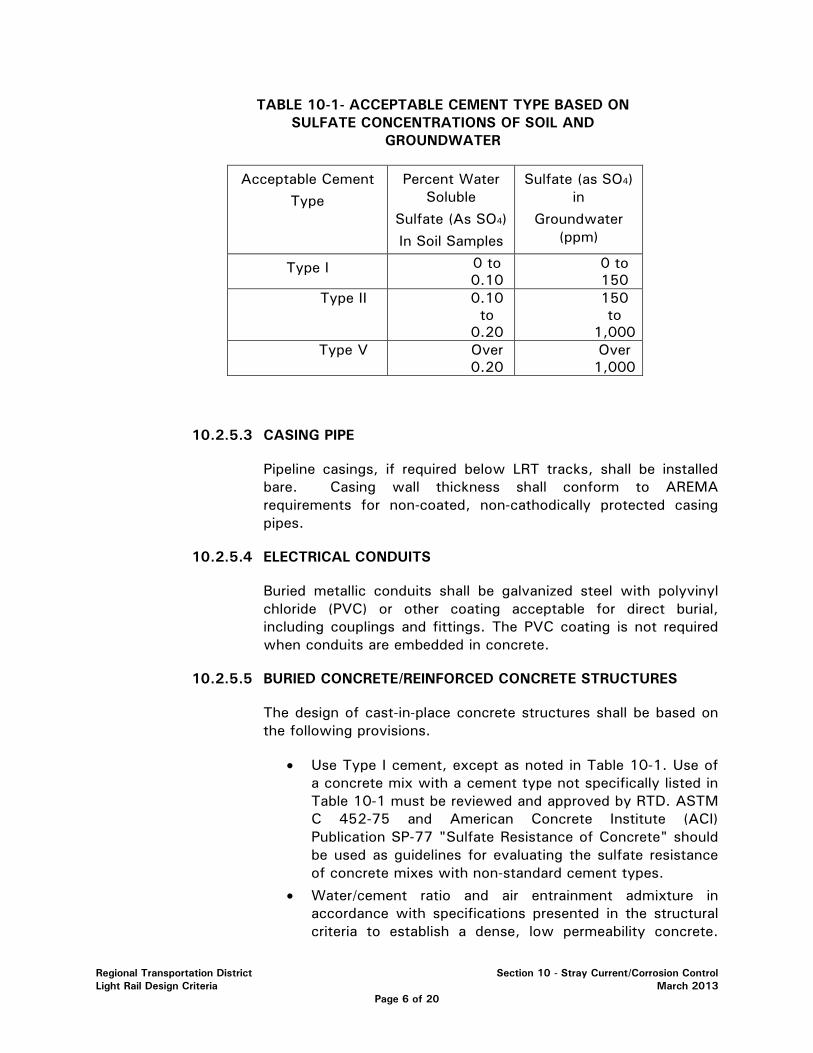
Regional Transportation District Section 10 - Stray Current/Corrosion Control Light Rail Design Criteria March 2013
Page 6 of 20
TABLE 10-1- ACCEPTABLE CEMENT TYPE BASED ON SULFATE CONCENTRATIONS OF SOIL AND
GROUNDWATER
Acceptable Cement Type
Percent Water Soluble
Sulfate (As SO4) In Soil Samples
Sulfate (as SO4) in
Groundwater (ppm)
Type I 0 to 0.10
0 to 150
Type II 0.10 to
0.20
150 to
1,000 Type V Over
0.20 Over 1,000
10.2.5.3 CASING PIPE
Pipeline casings, if required below LRT tracks, shall be installed bare. Casing wall thickness shall conform to AREMA requirements for non-coated, non-cathodically protected casing pipes.
10.2.5.4 ELECTRICAL CONDUITS
Buried metallic conduits shall be galvanized steel with polyvinyl chloride (PVC) or other coating acceptable for direct burial, including couplings and fittings. The PVC coating is not required when conduits are embedded in concrete.
10.2.5.5 BURIED CONCRETE/REINFORCED CONCRETE STRUCTURES
The design of cast-in-place concrete structures shall be based on the following provisions.
• Use Type I cement, except as noted in Table 10-1. Use of a concrete mix with a cement type not specifically listed in Table 10-1 must be reviewed and approved by RTD. ASTM C 452-75 and American Concrete Institute (ACI) Publication SP-77 "Sulfate Resistance of Concrete" should be used as guidelines for evaluating the sulfate resistance of concrete mixes with non-standard cement types.
• Water/cement ratio and air entrainment admixture in accordance with specifications presented in the structural criteria to establish a dense, low permeability concrete.
Regional Transportation District Section 10 - Stray Current/Corrosion Control Light Rail Design Criteria March 2013
Page 7 of 20
Refer to applicable sections of ACI 201.2R "Guide to Durable Concrete".
• Maximum chloride concentration of 250 ppm in the total mix (mixing water, aggregate, cement, and admixtures). The concrete mix should be such that the water soluble and acid soluble chloride concentrations, at the concrete/reinforcing steel interface, do not exceed 0.15 and 0.2% by weight of cement, respectively, over the life of the structure. Refer to applicable sections of ACI 222R "Corrosion of Metals in Concrete".
• Concrete cover over reinforcing steel shall comply with American Concrete Institute (ACI) codes and provide a minimum of 2 inches of cover on the soil/rock side of reinforcement when pouring within a form and a minimum of 3 inches of cover when pouring directly against soil/rock.
• The need for additional measures, as a result of localized special conditions, shall be determined on an individual basis. Additional measures may include application of protective coating to concrete, reinforcing steel, or both.
Precast standardized facilities, such as vaults and manholes, must be reviewed on an individual basis to determine alternative criteria when they cannot be practically modified to meet some or all of the provisions specified herein.
Precast segmented concrete ring construction shall meet the requirements of this Section or be reviewed on an individual basis to determine alternative criteria when they cannot be practically modified to meet some or all of the provisions specified.
Below Grade Shotcrete
• Below grade shotcrete used for permanent support shall be in accordance with ACI 506.2 and applicable provisions specified in this Section. In the case of conflicting specifications, the more rigid or conservative specification shall be applicable.
• No special corrosion control measures are required for shotcrete applications, which are not considered as providing permanent support.
10.2.5.6 SUPPORT PILINGS
The following is applicable only to support piling systems, which are to provide permanent support. Pilings used for temporary support do not require corrosion control provisions.
Regional Transportation District Section 10 - Stray Current/Corrosion Control Light Rail Design Criteria March 2013
Page 8 of 20
Designs based on the use of metallic supports exposed to the environment, such as H or soldier piles, shall consider the use of barrier coatings. The need for coatings and/or special measures, such as cathodic protection, shall be determined on an individual basis, based on type of structure, analysis of soil borings for corrosive characteristics, and the degree of anticipated structural deterioration caused by corrosion.
Reinforced concrete piling, including fabrications with prestressed members, shall be designed to meet the following minimum criteria:
• Water/cement ratio and cement types in accordance with Section 10.2.5.5.
• Chloride restrictions for concrete with non-prestressed members shall be in accordance with Section 10.2.5.5.
• Chloride restrictions for concrete with prestressed members shall be in accordance with Section 10.2.5.5, with exception that the concrete mix should be such that the water soluble and acid soluble chloride concentrations, at the concrete/prestressed steel interface, do not exceed 0.06 and 0.08 percent by weight of cement, respectively, over the life of the structure. Refer to ACI 222R "Corrosion of Metals in Concrete".
• A minimum of 3 inches of concrete cover over the outermost reinforcing steel, including prestressing wires, if present.
Concrete-filled steel cylinder columns, where the steel is an integral part of the load bearing characteristics of the support structure, shall be designed considering the need for special measures, such as increased cylinder wall thickness, external coating system, and/or cathodic protection. The design shall be determined on an individual basis, based on type of structure, analysis of soil borings for corrosive characteristics and the degree of anticipated structural deterioration caused by corrosion. Chloride restrictions shall be in accordance with Section 10.2.5.5
10.2.5.7 REINFORCED CONCRETE RETAINING WALLS
Cast-in-place concrete retaining walls shall be in accordance with the requirements in Section 10.2.5.5.
Modular-type retaining walls with restraining devices or reinforcing strips placed beneath the LRT tracks shall meet the requirements in Section 10.2.5.5, FHWA Publication No. FHWA-NHI-00-044, and require special consideration for stray current mitigation due

Regional Transportation District Section 10 - Stray Current/Corrosion Control Light Rail Design Criteria March 2013
Page 9 of 20
to the location of critical structural components. Designers must provide for stray current and soil corrosion control for modular retaining walls with structural support components beneath the LRT tracks.
Modular-type retaining walls that do not place critical structural components beneath the tracks shall meet the requirements in Section 10.2.5 5, FHWA Publication No. FHWA-NHI-00-044, and the following or be reviewed on an individual basis to determine alternative criteria when they cannot be practically modified to meet some or all of the provisions specified below.
• Embedded and buried steel reinforcing members of the modules should be constructed without special provisions for establishing electrical continuity.
• Steel reinforcing strips of adjacent modules should not be electrically interconnected. The reinforcing strips should be coated with a fluidized bed epoxy resin system or coal tar epoxy system.
• Tie-strips should be coated with a fluidized bed epoxy resin system or coal tar epoxy system prior to module construction.
• The tie-strips should not make electrical contact to the reinforcement steel in each module. A minimum 1 inch separation should be maintained.
• Longitudinal reinforcing steel within precast concrete parapets and cast-in-place junction slabs should not be made electrically continuous.
Pre-stressed/post-tensioned concrete cylinder pressure pipe shall not be designed for use in the vicinity of the LRT tracks or substations without review on an individual basis to determine alternate materials of construction. If these types of piping are used, the following items shall be addressed in the design.
• Possibility of hydrogen embrittlement of highly stressed steel components
• Provisions for electrical continuity within the manufactured pipe
• Provisions for electrical continuity of mechanical fittings and pipe joints
• Provisions for monitoring stray currents and hydrogen over voltages
• Provisions for reducing stray currents through the use of dielectric coatings or encasements
• Possible consequences of a failure of the pipe

Regional Transportation District Section 10 - Stray Current/Corrosion Control Light Rail Design Criteria March 2013
Page 10 of 20
10.3 STRAY CURRENT CORROSION CONTROL
This section provides criteria for designs to minimize the corrosive effect of DC stray current from transit operations on transit structures and adjacent structures owned by others.
Stray current control shall primarily reduce or limit the level of stray current at the source, under normal operating conditions, rather than trying to mitigate the corresponding effects (possibly detrimental), which may otherwise occur on transit facilities and other underground metallic structures. The basic requirements for stray current control are as follows:
• Operate the mainline system with no direct or indirect electrical connections between the positive and negative traction power distribution circuits and ground.
• Design the traction power system and trackwork to minimize stray earth current during normal revenue operations.
10.3.1 TRACTION POWER SYSTEM
Traction power supply system shall be designed as a dedicated system, providing power solely to the light rail line. Joint use of traction power facilities, except for common civil structures, is not permitted. Individual traction power supply system for the light rail line shall be designed with two electrically isolated, independent subsystems for the mainline and maintenance shop.
10.3.1.1 TRACTION POWER SUBSTATIONS (MAINLINE)
Traction power substations shall be spaced at intervals such that maximum track-to-earth potentials do not exceed 50 volts during normal operations. Consider locating TP substations close to passenger stations and other track sections with high anticipated vehicle acceleration.
Substations shall be provided with stray current test facilities to allow for monitoring the voltage between the negative bus and the substation ground mat. Space shall be provided in each substation for future installation of portable stray current monitoring equipment.
10.3.1.2 POSITIVE DISTRIBUTION SYSTEM
Positive distribution system shall be normally operated as an electrically continuous bus, with no breaks, except during emergency or fault conditions. Intentional electrical segregation of mainline, yard and shop positive distribution systems is the only type of segregation permitted.
Regional Transportation District Section 10 - Stray Current/Corrosion Control Light Rail Design Criteria March 2013
Page 11 of 20
Overhead contact systems (OCS), consisting primarily of support poles, the contact wire and, where applicable, the messenger wire, shall be designed to meet the following minimum requirements and include the following minimum provisions:
• A maximum leakage current to ground of 2.5 milliamperes per mile of single track OCS with 2,500 volts DC applied between the OCS and ground.
10.3.1.3 MAINLINE NEGATIVE RETURN SYSTEM
Running Rails
The mainline running rails, including special trackwork, grade crossings and all ancillary system connections, shall be designed to have a minimum, uniformly distributed, in-service track-to-earth resistance:
o Special trackwork and concrete tie & ballast track: 500 ohm- 1000-feet (2 rails)
o Direct fixation track: 500 ohm-1000-feet (2 rails)
The criteria shall be met through the use of appropriately designed insulating track fastening devices, such as insulated tie plates, insulated rail clips, direct fixation fasteners, rail fastener coating or other approved methods.
Ballasted track construction shall meet the following minimum provisions:
• Use of a hard rock, non-porous, well drained ballast material free of dirt or debris.
A minimum 1 inch clearance between the ballast material and all metallic surfaces of the rail and metallic track components in electrical contact with the rail.
Mainline tracks shall be electrically insulated from the yard tracks by use of insulated rail joints in both rails of each track. Location of the insulating joints shall be chosen to reduce the possibility of a vehicle bridging the insulator for a time period longer than that required to move a vehicle into or out of the yard.
Mainline tracks shall be electrically insulated from foreign railroad connections (sidings) by use of insulating rail joints. Location of the insulating joints shall be chosen to reduce the possibility of a vehicle bridging the insulator(s) for a time period larger than required to move onto or off of mainline.
Regional Transportation District Section 10 - Stray Current/Corrosion Control Light Rail Design Criteria March 2013
Page 12 of 20
Embedded trackwork at stations, crosswalks, turnouts, crossovers, grade crossings. Embedded trackwork shall meet the following minimum provisions:
• Electrical insulating material shall be provided between the rail and all embedment materials and precast track panels exhibiting a minimum volume resistivity of 1 x 10¹⁴ Ohm-Centimeters as measured in accordance with ASTM D-257.
• All track fastener components and the top of rail bases under flangeway filler installed for embedded track shall be coated with a corrosion-resistant material such as Petrolatum or approved equal.
• The surface profile of the finished grade adjacent to the rails shall be sloped away from the rail to allow for drainage and reduced accumulation of debris.
• The surface profile of the finished grade within 6-inches of the rail shall be a smooth finish to support maintenance and cleaning.
Ancillary Systems
Switch machines, signaling devices, train communication systems, and other devices or systems which may contact the rails shall be electrically isolated from earth. The criteria shall be met through the use of dielectric materials electrically separating the devices/systems from earth, such that the criterion given in Section 10.3.1.3 is met.
Electrical Continuity
The running rails shall be constructed as an electrically continuous power distribution circuit through use of either rail joint bonds, impedance bonds, continuously welded rail or a combination of the three, except for the use of insulated rail joints at the locations noted in Sections 10.3.1.3 and 10.3.1.4.
10.3.1.4 MAINTENANCE SHOP
Shop traction power shall be provided by a separate dedicated DC power supply electrically segregated in both the positive and negative DC power circuits from the yard traction power system and the mainline system.
Shop track shall be electrically connected to the shop building and shop grounding system.
Other electrically grounded track, such as blowdown pit tracks, car wash tracks and interconnecting switching tracks between
Regional Transportation District Section 10 - Stray Current/Corrosion Control Light Rail Design Criteria March 2013
Page 13 of 20
these facilities shall be electrically insulated from the yard tracks and powered from the shop traction power supply via designated feeders.
10.3.1.5 WATER DRAINAGE
Below grade sections shall be designed to prevent water from dropping or running onto the running rails and rail appurtenances and shall be designed to prevent the accumulation of freestanding water.
Water drainage systems for sections exposed to the environment shall be designed to prevent water accumulation from contacting the rails and rail appurtenances.
10.3.2 TRANSIT FIXED FACILITIES
10.3.2.1 AERIAL TRACKWAY STRUCTURES
Direct Fixation Bridges
This section applies to aerial structures and bridges with cast-in-place decks, bare steel reinforcement, and insulated direct fixation trackwork construction.
• Provide electrical continuity of top layer reinforcing steel in the deck/girder by welding all longitudinal lap splices.
• Electrically interconnect all top layer longitudinal reinforcing steel by welding to transverse collector bars installed at breaks in longitudinal reinforcing steel, such as at expansion joints, hinges and at abutments. Connect collector bars installed on each side of a break with a minimum of two cables.
• Provide additional transverse collector bars at intermediate locations to maintain a maximum spacing of 500 feet between collector bars.
• Provide a ground electrode system at each end of the structure and at intermediate locations to maintain a maximum spacing between ground electrode systems of 750 feet. The number, location and earth resistance of the ground electrode system must be determined on an individual structure basis.
• Provide test facilities at each ground electrode system location. The facilities will house test wires from the collector bars and provide access to the ground electrode system.
Regional Transportation District Section 10 - Stray Current/Corrosion Control Light Rail Design Criteria March 2013
Page 14 of 20
• All copper to steel weld locations (bond cables) shall require coating with a cold applied, fast drying mastic consisting of bituminous resins and solvents.
• Bonding, grounding systems and test facilities are not required if epoxy coated reinforcing steel is used in the deck.
Tie and Ballast Bridges
This section applies to aerial structures with insulated tie and ballast track construction. Welding of reinforcing steel in the deck is not required for this configuration.
• Provide a waterproofing, electrically insulating membrane (with protection board) over the entire surface of the deck that will be in contact with the ballast. The membrane system shall have a minimum volume resistivity of 1010 (10 billion) ohm-centimeters.
• An alternate method to the use of insulating membrane (with protection board) is the use of spray applied polyurea. RTD approval is required prior to the use of the alternate system.
Existing Concrete Deck Structures, Tie and Ballast
This section applies to existing aerial structures used for LRT installation. Stray current corrosion control for existing aerial structures shall be addressed by limiting earth current levels at the source (running rails). Meeting the criteria established in Section 10.3.1 and those items indicated below will provide the primary stray current control for these facilities.
• Provide a waterproofing, electrically insulating membrane (with protection board) over the entire surface of the deck that will be in contact with the ballast. The membrane system shall have a minimum volume resistivity of 1010 (10 billion) ohm-centimeters.
• An alternate method to the use of insulating membrane (with protection board) is the use of spray applied polyurea. RTD approval is required prior to the use of the alternate system.
10.3.2.2 OVERHEAD CONTACT SYSTEM (OCS) POLE FOUNDATION GROUNDING
OCS Poles on Aerial Structures. OCS poles located on aerial structures shall include either of the following minimum set of provisions, depending on the type of aerial structure.
Regional Transportation District Section 10 - Stray Current/Corrosion Control Light Rail Design Criteria March 2013
Page 15 of 20
• Where the aerial structure includes welded deck reinforcing steel connected to a ground electrode system, electrically interconnect the OCS support poles on the structure and connect these poles to the ground electrode system.
• Cabling used to interconnect the poles and the ground electrode system shall be sized based upon anticipated fault current and fault clearing time.
• The cabling shall be routed in conduit and terminated in junction boxes or test cabinets that also house wires from the deck reinforcing steel and the ground electrode system.
• Cabling shall be designed to allow for connection of interconnected OCS poles along the aerial structure to all ground electrode systems installed with a particular aerial structure.
10.3.2.3 RTD OWNED METALLIC FACILITIES
All piping and conduit shall be non-metallic, unless metallic facilities are required for specific engineering purposes. There are no special provisions required if nonmetallic materials are used. All new, buried, metallic pressurized piping owned by RTD shall be cathodically protected as described in Section 10.2.2.
Metallic Facilities (System wide)
• Pressure or non-pressure piping exposed within crawl spaces or embedded in concrete inverts shall not require special provisions.
• Pressure piping that penetrates station walls shall be electrically insulated from the external piping to which it connects, wall reinforcing steel, and from watertight wall sleeves.
Metallic Facilities (Shop)
All reinforcing steel, structural steel, and rails within the shop building shall be electrically connected to a common grounding grid.
• All pressure piping within the shop building or perimeter of the shop foundation or foundation slab shall have the following minimum provisions: o Designed to be run above or within the foundation slab.
Below slab installations must be reviewed on an individual basis to determine the need for special measures.

Regional Transportation District Section 10 - Stray Current/Corrosion Control Light Rail Design Criteria March 2013
Page 16 of 20
o Electrical insulation from interconnecting pressure piping located outside the shop building or perimeter of the foundation/foundation slab. Locate insulating devices above grade or inside the building, in lieu of burying directly.
o Electrical insulation from watertight wall/floor sleeves and wall reinforcement.
o Electrical connection to the shop common ground grid at sufficient locations, such that there will be only negligible potential differences between the piping and grounding network during fault and normal conditions.
Metallic Facilities (Yard)
• All buried pressurized piping shall meet the criteria of Section 10.2.0 and include the following minimum provisions: o Electrical continuity as described in Section 10.2.4.3. o Electrical insulation from interconnecting non-transit
facilities and possibly additional insulation to establish discrete electrical units.
o Test/access facilities installed at all insulated connections and at intermediate locations as determined during final design.
10.3.3 FACILITIES OWNED BY OTHERS
10.3.3.1 REPLACEMENT/RELOCATED FACILITIES
Stray current corrosion control for new and/or relocated pressurized piping systems that cross below LRT tracks shall be addressed using cathodic protection systems. See Section 10.2.3 for cathodic protection requirements for piping systems owned by others.
10.3.3.3 EXISTING BRIDGE STRUCTURES
Stray current corrosion control for existing bridge structures shall be addressed by limiting earth current levels at the source (running rails). Meeting the criteria established in Sections 10.3.1.1, 10.3.1.2, and 10.3.1.3 will provide the primary stray current control for these facilities.
10.4 ATMOSPHERIC CORROSION PROTECTION
Methods for controlling atmospheric corrosion shall include, but not necessarily be limited to the following:
Regional Transportation District Section 10 - Stray Current/Corrosion Control Light Rail Design Criteria March 2013
Page 17 of 20
• Materials selection – Acceptable materials shall have proven performance records for the service application.
• Protective coatings – Barrier of sacrificial coatings shall be used on steel.
• Design – Recess moisture traps and dissimilar metal couples shall be avoided.
• Sealants – Accumulation of moisture in crevices shall be prevented by the use of sealants.
All wayside electrical equipment such as signals and communications equipment, electrical motors, control panels, switchgear, etc. shall be enclosed in temperature controlled environments or otherwise incorporate design techniques to prevent moisture condensation and corrosion of integral parts.
10.4.1 METALLIC MATERIALS (GENERAL)
Structures that may be affected by atmospheric corrosion shall be identified, including, but not necessarily limited to:
• Exposed metallic surfaces on mainline structures
• Exposed metallic surfaces at passenger stations
• Catenary installations and related metallic hardware
• Right-of-way and enclosure fences
• Electrical, mechanical, signal, and communication devices and equipment, and signal and traction power substation housings
• Vehicles
10.4.2 STEEL AND FERROUS ALLOYS
Carbon steel and cast iron exposed to the atmosphere shall have a coating applied to all external surfaces. Rail and rail fasteners do not require coatings except when used for the purpose of dielectric insulation. High strength low alloy steels shall be protected in a manner similar to carbon steels except where used as weathering steel exposed to outside environments. Coating of metallic contacting surfaces, crevice sealing, and surface drainage shall be addressed in the designs. Staining of adjacent structures shall be considered.

Regional Transportation District Section 10 - Stray Current/Corrosion Control Light Rail Design Criteria March 2013
Page 18 of 20
10.4.3 COPPER ALLOYS
Copper and its alloys can be used where exposed to the weather without additional protection. Bimetallic couples shall be avoided.
10.4.4 ZINC ALLOYS
Zinc alloys can be used without additional protection. Bimetallic couples shall be avoided.
10.4.5 ALUMINUM ALLOYS
Use an anodized finish to provide the best weather resistant surface. Bimetallic couples shall be avoided.
10.4.6 COATING SYSTEMS
Coatings shall have established performance records for the intended service and be compatible with the base metal to which they are applied. Coatings shall be able to demonstrate satisfactory gloss retention, color retention, and resistance to chalking over their minimum life expectancies. Coatings shall have minimum life expectancies, defined as the time prior to major maintenance or reapplication, of 15 to 20 years.
10.5 QUALITY CONTROL TESTING
10.5.1 ELECTRIC CONTINUITY
The electrical continuity of reinforcement and utility structures is required by the design criteria. The requirements for determining the proper electrical characteristics of these structures shall be incorporated into the design of the structure. The following paragraphs establish the guidelines for developing the quality control test procedures for electrical continuity.
• All structures that are to be made electrically continuous shall be tested for electrical continuity, compared to theoretically based criteria, and meet or exceed the accepted criteria.
• Incorporate a specific set of test procedures and acceptance criteria to be followed for the electrical continuity testing into the project specifications.
• Incorporate selection criteria for the test entities to perform the quality control testing including the qualifications of the agency, personnel requirements and equipment requirements. A minimum of 5 years of experience performing this work is required.
• Incorporate specific reporting requirements for the electrical continuity testing.

Regional Transportation District Section 10 - Stray Current/Corrosion Control Light Rail Design Criteria March 2013
Page 19 of 20
10.5.2 CATHODIC PROTECTION
The application of cathodic protection on the underground utility structures is required by the design criteria. The requirements for determining proper application of cathodic protection include the verification of electrical continuity (Section 10.5.1) and verification of cathodic protection compliance with industry standards (NACE International). The following paragraphs establish the guidelines for developing the quality control test procedures for verification of proper cathodic protection levels.
• All structures that are required to have cathodic protection shall be tested in accordance with NACE International RP0169.
• A test plan shall be submitted by the testing agency to be approved by the RTD.
• Incorporate specific reporting requirements for the cathodic protection testing.
• Incorporate selection criteria for the testing entities to perform the quality control testing including the qualifications of the agency, personnel requirements, and equipment requirements. A minimum of 5 years of experience performing this work is required.
10.5.3 COATINGS
The quality control measures required for the verification of proper application and handling vary greatly depending on the coating type. The following guidelines establish general procedures for the quality control testing.
• Coatings shall be tested in accordance with the manufacturer’s recommendations and in accordance with NACE International Recommended Practices.
• A quality control test plan shall be required for the application and testing of all coated surfaces. The test plan shall address the allowable coating thickness measurements, adhesion requirements, hold points for test, test procedures to be used in the quality control process, and the reporting and acceptance requirements for each specific type of coating system being used.
• All shop coated surfaces shall first be tested, witnessed, and accepted at the coating facility. Additional field quality control hold points shall be required.
• Incorporate selection criteria for the testing entities to perform the quality control testing including the qualifications of the agency, personnel requirements, and equipment requirements. A minimum of 10 years of experience performing this work is required.

Regional Transportation District Section 10 - Stray Current/Corrosion Control Light Rail Design Criteria March 2013
Page 20 of 20
10.5.4 TRACK-TO-EARTH RESISTANCE TESTING
The track-to-earth resistance of the running rails is the primary barrier for the control of stray current discharge from the negative system. The requirements for conducting this testing are as follows:
• Incorporate a specific set of industry standard test procedures and acceptance criteria to be followed for the track-to-earth testing into the project specifications.
• Incorporate selection criteria for the testing entities to perform the quality control testing including the qualifications of the agency, personnel requirements, and equipment requirements. A minimum of 10 years of experience performing this work is required.
• Incorporate specific reporting requirements for the track-to-earth resistance testing.
RTD Design Guidelines & Criteria Section 11-Operations Facility Light Rail Design Criteria March 2013
Page 1 of 5
SECTION 11 - OPERATIONS FACILITY
11.1 GENERAL…………………………………………………………………………………………. 2
11.2 MAINTENANCE GUIDELINES…………………………………………………………………..2
11.3 MAINTENANCE FACILITY COMPONENTS…………………………………………………..2
11.4 MAINTENANCE FACILITY AREAS AND FUNCTIONS……………………………………..3
11.5 YARD LAYOUT…………………………………………………………………………………..4
11.6 DESIGN REQUIREMENTS……………………………………………………………………….5

RTD Design Guidelines & Criteria Section 11-Operations Facility Light Rail Design Criteria March 2013
Page 2 of 5
SECTION 11 - OPERATIONS FACILITY 11.1 GENERAL This section outlines the functional requirements and basic criteria for the planning and design of facilities for the inspection, maintenance, repair and storage of the regional Transportation District (RTD) light rail system. These criteria are to be used in the development of a more in-depth study to determine specific design parameters. The criteria for this section have been prepared to interface with the type of equipment currently being used as well as provide for potential growth of the fleet and changing technology. The LRT Operations Facility shall be sited and designed based on RTD’s light rail route structure, the type of equipment to be used (or being used) within the system, space availability and operational and future route expansion requirements. The capacity requirements for maintenance and inspection will be determined by the size of the in-service fleet, the characteristics of the fleet and the amount of time allocated for maintenance and inspection by the train schedules. This guideline does not establish a certain, specific approach to maintenance, but rather is a general overview of the basic requirements of the facility. 11.2 MAINTENANCE GUIDELINES The fleet shall require a certain level of maintenance structured along the following guidelines:
• Daily Service and Inspection • Programmed Life Cycle Maintenance • Running Repair and Corrective Maintenance • Heavy Repair • Mid-Life Overhaul
Information concerning the type of LRV in the RTD fleet can be found in "RTD Light Rail Design Criteria Chapter 13 –Light Rail Vehicle." 11.3 MAINTENANCE FACILITY COMPONENTS The overall operations facility layout shall include (but not be limited to) the following:
a) Tracks for Light Rail Vehicle Storage and Circulation b) LRT Transportation Report Area c) LRV Maintenance Shop d) LRT Spare Parts Depot e) LRT MOW Shop or Area f) Parking (employee and visitor), Service and Access Roads g) Hi-Rail Vehicle Facility h) LRV Cleaning and Wash Facilities i) Outside Storage Areas j) Yard Security Fencing
RTD Design Guidelines & Criteria Section 11-Operations Facility Light Rail Design Criteria March 2013
Page 3 of 5
k) Yard Janitor Houses l) Emergency Uninterrupted Power Supply m) Equipment (incl. LRV) Off-Loading Area n) Isolated Traction Power With Adequate Catenary System
11.4 MAINTENANCE FACILITY AREAS AND FUNCTIONS RTD's LRT Operations Facility shall house (but not be limited to) the following functions:
a) Rail Transportation Administration b) Rail Maintenance Administration c) Rail Operations Planning d) Rail Maintenance Engineering e) Control Center f) Rail Training Administration g) LRV Body Shop (including frame straightening) h) LRV Paint Shop i) Complete vehicle overhaul j) Service, remove & replace car pantograph assemblies, and brake resistors k) Extensive LRV modifications l) Traction Electrification System (TES) Service and Inspection m) Wheel Truing n) Wheel & Axle Presses o) LRV Truck Maintenance, Repair and Replacement p) Electronic Component Repair q) Signal Relay Inspection & Calibration r) Covered storage of LRT Maintenance-of-Way (MOW) Materials s) LRV Re-railing t) Facilities Maintenance u) LRT Parts Storage and Inventory System v) Light Rail Vehicle (LRV) Storage w) LRT Operator Report Area x) LRV Service and Inspection y) Safety inspections z) LRV Air Conditioning and Current Collector Unit Repair aa) Rail-bound Equipment Storage bb) Enclosed LRV Interior and Exterior Cleaning cc) Shop work areas dd) Sand box filling ee) Loading/off-loading equipment to/from rail bound equipment ff) Battery room gg) Sufficient numbers and types of cranes, hoists and jacks hh) Restrooms and Locker/Shower Rooms ii) Conference Rooms and Lunch Room
The shop layout shall follow certain design guidelines as closely as funds and site configuration permit. These guidelines relate to the relative location of work spaces to each other within the shop, areas of the spaces for the type of activity or function, utilities

RTD Design Guidelines & Criteria Section 11-Operations Facility Light Rail Design Criteria March 2013
Page 4 of 5
requirements, etc. The shop layout shall be designed to separate work functions so that cars may be inspected, serviced and returned to revenue operation as quickly as possible and with minimal interference between services. Additionally, coordination with local agencies and jurisdictions is required to determine and approve fire protection, safety, security and environmental measures that will be implemented as part of the planning, design and construction of the facility. Isolated traction power shall be provided for the shop (including wash bays) and yard storage tracks. Overhead wire in the yard and in the shop shall be sectionalized to allow the shutdown of power to specific car positions in the shop and tracks in the yard without affecting the remainder of the yard or shop. 11.5 GENERAL YARD LAYOUT The yard layout (footprint) shall be based upon storage and movement needs for forecasted design year ridership levels. Enough level, tangent track shall be included in the yard layout to accommodate the anticipated number of LRTs. Direct access to and from the RTD mainline to the storage tracks is required, preferably operating two lead tracks from the mainline to the storage yard to permit the simultaneous receiving and dispatching of trains. The storage yard shall be adjacent to the shop. The many diverse yard functions, plus the critical time requirements directly preceding, during and after peak hour operations, necessitate a yard configuration that provides maximum train movement flexibility with minimal interference with normal operations. Track construction within the yard shall comply with "RTD Light Rail Design Criteria Chapter 4 -Trackwork." Access for truck delivery, including semi-trucks and trailers shall be provided. Service roads shall be provided around the shop, between selected LRT tracks, and to outdoor storage areas within the yard.
The yard shall be adequately lighted for 24-hour operation. Operations facility security shall be achieved by fencing the periphery of the yard, by lighting and by observation from the administration and operations areas of the building. Access shall be via secured gates. The overall storage yard layout footprint shall have adequate drainage such that normal operations are not interrupted. Landscaping shall be minimal. The amount and type shall be consistent with the local zoning ordinance for the site. Parking or provisions for future parking shall be provided for visitors and employees to a level adequate to accommodate the parking needs of the two largest shift changes. An approved system for the collection and temporary storage of hazardous material shall be included.
RTD Design Guidelines & Criteria Section 11-Operations Facility Light Rail Design Criteria March 2013
Page 5 of 5
11.6 DESIGN REQUIREMENTS Design requirements for the building and yard shall comply with all federal, state, and local laws, regulations, rules, requirements, and shall uphold the preservation of natural resources (environmental) as well as all laws, ordinances, rules, regulations and lawful orders of any public entity bearing on the performance of the work. Architectural treatments (interior and exterior) should be decided as part of the coordination efforts between RTD and the consultant. Listed below (but not limited to) are the principal applicable codes (latest version is to be used):
a) International Building Code b) International Mechanical Code c) National Electric Code d) National Electric Safety Code e) International Plumbing Code f) National Fire Protection Association (NFPA) g) American National Standard Code for Elevators h) American Society of Heating, Refrigeration and Air-Conditioning Engineers, Inc.
(ASHRAE) i) Occupation Safety and Health Administration (OSHA) j) Illuminating Engineering Society of North America k) American National Standards Institute, Inc. l) American Railway Engineering and Maintenance-of-Way Association (AREMA) m) Americans with Disabilities Act, including U.S. Department of Transportation,
Final Rule - Transportation for Individuals with Disabilities n) County and City Zoning and Building Regulations o) Federal Railroad Administration – Office of Safety Assurance and Compliance
guidelines for inspection p) ASCE/SEI 7-10 (or latest version) “Minimum Design Loads for Buildings and
Other Structures”, American Society of Civil Engineers. The facility shall be designed to meet applicable federal, state and local codes for accommodating access for the mobility impaired in effect at the time of facility design. In planning and designing the facility, RTD's maintenance procedures shall be reviewed and Operations personnel shall be consulted to ensure that the new facility provides an efficient work environment and meets the needs of RTD Operations personnel.
Regional Transportation District Section 12 - Fare Collection Equipment Light Rail Design Criteria March 2013
Page 1 of 9
SECTION 12 - FARE COLLECTION EQUIPMENT
12.1 GENERAL ................................................................................................ 2 12.2 AUTOMATED FARE COLLECTION ............................................................... 2 12.3 TICKET VENDING MACHINES .................................................................... 2 12.4 MODULARITY .......................................................................................... 3 12.5 CODE REQUIREMENTS ............................................................................. 3 12.6 DESIGN LIFE ............................................................................................ 3 12.7 OPERATING ENVIRONMENT REQUIREMENTS .............................................. 4 12.8 ELECTRICAL ............................................................................................ 4 12.9 PASSENGER ACCESS ............................................................................... 4 12.10 CONSTRUCTION/EQUIPMENT ENCLOSURE ................................................. 5 12.11 MAINTAINABILITY AND ACCESSIBILITY ..................................................... 5 12.12 SAFETY .................................................................................................. 5 12.13 SECURITY ............................................................................................... 6 12.14 AESTHETIC REQUIREMENTS ..................................................................... 6 12.15 PROTECTION AGAINST VANDALISM AND BURGLARY ................................. 6 12.16 CENTRAL DATA SYSTEM ......................................................................... 7
12.16.1 DATA NETWORKING ............................................................................. 7 12.16.2 CENTRAL COMPUTER ............................................................................ 7 12.16.3 APPLICATION SOFTWARE ...................................................................... 8 12.16.4 DATABASE SOFTWARE ......................................................................... 8 12.16.5 REPORT GENERATION ........................................................................... 8 12.16.6 SYSTEM STATUS AND SECURITY MONITORING ....................................... 8 12.16.7 CONFIGURATION MANAGEMENT ............................................................ 9
Regional Transportation District Section 12 - Fare Collection Equipment Light Rail Design Criteria March 2013
Page 2 of 9
SECTION 12 - FARE COLLECTION EQUIPMENT
12.1 GENERAL
The Fare Collection System shall consist of Ticket Vending Machines (TVMs), a Central Data Collection & Information System (CDCIS), Smart Media Technology (SMT) System, Stand Alone Validators (SAVs), spare parts, special tools, test equipment, documentation, training, technical assistance and warranty as part of the System. The TVMs, SMTs and SAVs shall be designed for outdoor installation in an un-sheltered environment, including precipitation, sun glare, heat and solar loading. Any equipment supplied and/or installed, that is not housed in an environmentally controlled enclosure shall be rated to operate in the environmental conditions of the Denver Metro area.
Even though TVMs, SMTs and SAVs are to be designed for outdoor installation, they shall be located under a shelter, unless approved by RTD. The orientation of the device shall face north whenever possible such that the legibility of the customer interface display panel is not affected by direct sunlight.
It is required that the TVMs, SMTs and SAVs (Fare Collection Equipment) shall be service proven. The System shall be of materials that are new and free of defects and which conform to the requirements of the Technical Specification.
12.2 AUTOMATED FARE COLLECTION
• All platforms shall have provisions for free-standing TVMs, SMTs and SAVs.
• RTD shall determine the number of initial machines and future provisions.
• Weather protection shall be provided for each machine unless otherwise approved by RTD.
• All TVMs & SMTs shall be protected from direct sunlight onto the screen.
12.3 TICKET VENDING MACHINES
In general, TVMs shall be designed to sell tickets and passes to RTD's customers by coins, bills or credit/debit cards. TVMs shall be capable of printing and issuing different tickets, passes, mag cards, smart cards, RFID cards or combination thereof from within the same housing. The design of the TVMs shall be based on simple, clear and reliable construction, and modular components to make them easy to use and maintain.
Each TVM shall be equipped to:
• Accept U.S. nickel ($.05), dime ($.10), quarter ($.25), and post-1978 dollar ($1.00) coins; RTD 0.0650 Token; U.S. one dollar, five dollar, ten dollar, twenty dollar, fifty dollar bills, credit/debit cards as payment;
• Provide change in the fewest number of coins as required;
• Respond to customer's choice of action;
• Issue tickets and passes;

Regional Transportation District Section 12 - Fare Collection Equipment Light Rail Design Criteria March 2013
Page 3 of 9
• Register the number of media of each type and price range issued and total value of fare media sold;
• Indicate malfunctions of the unit; and
• Include complete on-line TVM, SMT & SAV network capability with remote status monitoring, automatic polling for sales information, a complete audit and accounting system, ability to remotely command the Fare Collection equipment to reset and self-diagnose, ability to remotely modify operating parameters such as fare tables and ticket print layouts, and process all credit/debit card authorizations.
12.4 MODULARITY
Each TVM shall be a self-contained machine, complete with its own cabinet and mounting stand or base, and having integral light fixtures to illuminate the control face. Each TVM shall consist of a bill processing unit, coin processing unit, credit card processing unit (optional), debit card PIN pad (optional), display and information unit, change maker, ticket and pass issuing unit, key pad and function keys, power supply, and processing and control unit, all located within a self-contained unit. Each of the basic functions within the machine shall be performed by modular components which readily permit field replacement of inoperative modules to return the machine to service in minimal time. Control and power connections shall be made via plug-in connections. Modules shall not be directly hard wired together and/or into the TVMs. The individual module shall be fixed in the unitized frame with fast latching devices and be secured by locks against unauthorized removal, where required.
12.5 CODE REQUIREMENTS
TVMs shall be designed to comply with all applicable local or national design codes, ordinances, and standards existing at the time of procurement. Listed below are the principal applicable codes:
• National Electric Safety Code, American National Standard C2, latest edition
• National Electric Code, National Fire Protection Association ANSI/NFPA 70, latest edition
• Americans with Disabilities Act Accessibility Guidelines for Buildings and Facilities (ADAAG), latest edition
• Underwriters Laboratories UL-751, “Vending Machines,” latest edition
• International Electrotechnical Commission standard 529 (IEC529)
12.6 DESIGN LIFE
The Fare Collection System shall be designed for a minimum service life of 10 years of normal operation in the Denver metropolitan area. All equipment shall be designed to operate seven days per week, twenty-four hours per day.
Regional Transportation District Section 12 - Fare Collection Equipment Light Rail Design Criteria March 2013
Page 4 of 9
12.7 OPERATING ENVIRONMENT REQUIREMENTS
The Fare Collection System shall be capable of operating without shelter over an ambient temperature range of -15°F to 110°F. In the summer, direct sunlight conditions will cause cabinet temperature to rise considerably above ambient, in excess of 155°F. All equipment shall be capable of operating in relative humidity from 20% to 90% over the ambient temperature range given above. This shall include periods of condensation and wind-driven rain, freezing rain and snow. Equipment enclosures shall comply with International Electrotechnical Commission standard 529 (IEC529) level IP34 or equivalent.
12.8 ELECTRICAL
The Fare Collection System shall be designed to accept standard 3-wire, 115 volt, single phase, 60 Hz power. Each TVM shall be powered by a separate 30-amp circuit protected by circuit breaker. In addition, each TVM shall provide its own circuit protection. Each SMT/SAV shall be powered by a separate 20-amp circuit protected by circuit breaker.
All equipment shall be designed to tolerate 10% fluctuation in line voltage without any damage or service interruption. Breaks in the voltage (below 10% of the source voltage) or supply interruptions shall cause an orderly shutdown of the Equipment.
Voltage transient suppression shall be provided. The Fare Collection System shall include a protection system capable of withstanding transients of 3.0 kV peak pulse with a total energy of 1000 joules without damage, improper operation or shutdown. The functional status of any such surge and transient suppressor circuitry must be visible at all times when the outer door is open.
12.9 PASSENGER ACCESS
All functional controls, coin slots, bill slots, credit card slots, smart card readers, ticket slots and ticket and coin return bins shall be compliant with current Americans with Disabilities Act Accessibility Guidelines for Buildings and Facilities (ADAAG).
The TVM display shall use dark characters on a light background. Characters shall be at least 0.75 inches tall and be of sufficient contrast to make them easily readable in all ambient light conditions, including total darkness and direct sunlight. The TVM display shall utilize technology suitable for the environment and shall provide a viewing angle of least 45˚ from perpendicular in all directions. High-contrast raised lettering at least 0.625 inches high shall be used to label all controls, pushbuttons, coin and bill slots, and the ticket/coin return bin. All such labels shall also utilize standard Braille characters.
The TVM shall, on demand of the patron, provide audible voice instructions. The voice system shall utilize either stored human speech or synthesized speech using AT&T Natural Voices Software or approved equal. The messages shall be stored in digital form for operation and be modifiable by RTD. Context-sensitive voice messages shall provide, in audio form, the information shown on the TVM display or otherwise conveyed by the TVM. RTD will have final say in how the TVM looks and operates.

Regional Transportation District Section 12 - Fare Collection Equipment Light Rail Design Criteria March 2013
Page 5 of 9
12.10 CONSTRUCTION/EQUIPMENT ENCLOSURE
The Fare Collection System shall be designed to operate in unsheltered locations.
The overall dimension of an installed TVM shall not exceed 80 inches (height) by 38 inches (width) by 25 inches (depth). The equipment enclosure for the TVMs shall be of stainless steel with an unpainted random-orbital finish. The cabinet shall have a leveling base which shall accommodate the station platform surface slope. Mounting shall be by means of stainless steel bolts imbedded in concrete. The 6 inch thick concrete pad shall be larger than the width of the TVM base to ensure that the TVM base and the mounting bolts can accommodate the TVM installation.
Frames shall be provided for graphic panels on the front of the TVM as required for explaining the operation of the TVM. The top of the TVM shall slant at least 5˚ downward and to the rear of the TVM to prevent any accumulation of rain. The interior of the equipment shall be designed to allow easy and safe access to service equipment and sub-assemblies.
12.11 MAINTAINABILITY AND ACCESSIBILITY
In the design of The Fare Collection System, greatest emphasis shall be put on reliable operation of all components and equipment over their economic life, and to the minimization and simplification of scheduled and unscheduled maintenance tasks.
Equipment shall be modular in design to permit rapid field replacement of malfunctioning modules.
These units shall combine the advantages of relatively simple mounting and accessibility for maintenance. Adequate space shall be available to fit keys; to grasp, lift and turn internal components; and to remove and replace units, components, connections, and ticket stock. The weight of the units that must be lifted during servicing, except coin and bill vaults, and coin storage units when full, shall not exceed 37 pounds. Guide rails shall be provided to facilitate the removal of the modules. Adequate space for the use of tools shall be available as required. For ease of service, all electrical connections between components and sub-assemblies shall be established by means of coupling to allow rapid removal of a component and/or sub-assembly from the equipment.
12.12 SAFETY
The interior of the equipment shall be similarly free of sharp edges or other hazards that may cause injury to maintenance personnel. Particular attention shall be given to protecting blind persons who may explore the exterior surface with their fingers.
The exterior panels and control shall be grounded to prevent electrical leakage or static charge.
Regional Transportation District Section 12 - Fare Collection Equipment Light Rail Design Criteria March 2013
Page 6 of 9
12.13 SECURITY
Access to the interior of the equipment enclosures and to the cash vaults shall be restricted on a "need to gain access" basis as approved by RTD.
The arrangement of modular mechanical and electrical components and money containers shall be such that normal maintenance, including change-out of defective modules, shall neither require removal of, nor access into, the coin and bill containers.
TVM location shall be coordinated with CCTV camera angles to ensure the TVM is viewed by a camera.
12.14 AESTHETIC REQUIREMENTS
The Fare Collection System shall be designed with all controls and customer interface display and inputs on a common front face of the enclosure. Suitable graphics shall be provided explaining the operation of the equipment.
12.15 PROTECTION AGAINST VANDALISM AND BURGLARY
For protecting against vandalism and burglary for each TVM, the following requirements shall be met:
• All latches shall be secure and robust
• All external screws and hinges must be covered
• Security locks with profile catches must be used
• Locks must be drill resistant, mounted flush with the outside surface of the door
• The door must be locked with at least a three-point latching device with a bascule bolt and hook bar, or equivalent tools
• Overlapping doors must be constructed with a joining gap equal to or less than 2 mm
• Reinforcement must be provided at positions where there is danger of burglary
• The display screen must be protected by a fixed, transparent shield
Each TVM shall be equipped with a signaling and alarm system. TVMs shall be capable of surviving a kick or punch from a large adult acting in an irrational manner (acceleration pulses of 5 gravities peak value with approximate duration of 10 milliseconds along each of three mutually perpendicular axes) while the equipment is operating.
The signaling and alarm system shall be equipped with an electronic or mechanical siren capable of emitting a sound level of at least 110 dB(A) measured at a distance of three feet with the door open. This siren shall sound whenever unauthorized entry is detected or when severe impacts to the front door are detected.
An internal momentary contact switch, hidden inside the TVM but readily accessible, shall permit an authorized technician to trigger a “silent” alarm. When activated, this switch

Regional Transportation District Section 12 - Fare Collection Equipment Light Rail Design Criteria March 2013
Page 7 of 9
shall cause the TVM to notify the central computer system and/or SCADA, but not activate the siren.
12.16 CENTRAL DATA SYSTEM
The Fare Collection System shall communicate over the most efficient communications medium available to a centrally located data system. The equipment shall report status, events, alarms, and other information when necessary. All equipment shall also be able to receive information from the central computer to update fare structures, ticket print layouts, patron display information, operating parameters, and to be remotely commanded to perform certain diagnostic exercises.
While the central data system will be installed in the revenue shops, remote workstations shall provide users access to the data for queries, report generation and status information.
One or more such workstations shall be at the maintenance facility.
12.16.1 DATA NETWORKING
Data communications shall be provided in a hierarchical network, with a central control computer at the top level, an Ethernet switch at the middle level, and the TVMs at the lowest level.
All Fare Collection System shall be networked back to the central computer via Ethernet. RTD will make available one 10/100 Mbps Ethernet port at each station for communications over RTD’s IP-based network between the station and the revenue shop.
Ethernet switches, cabling and connectors shall be provided by the Contractor to communicate between the equipment and the RTD provided communications network. An SNMP capable managed Ethernet switch shall be provided at the station with enough ports to accommodate twice the original number of Fare Collection Equipment installed.
All outdoor cabling shall be suitable for outdoor/wet installations. Multi-mode fiber optic cabling and transceivers (suitable for the environmental conditions it is installed in) shall be provided for all TVM, SAV, and SMTs networking connections. Five RU of rack space will be provided by RTD in the communications room for installation of the fare collection communications equipment.
12.16.2 CENTRAL COMPUTER
The central computer shall be an IBM-compatible PC, suitably configured for the intended application. The computer shall be of dual-server architecture, with the second server in a “hot” spare configuration.
Regional Transportation District Section 12 - Fare Collection Equipment Light Rail Design Criteria March 2013
Page 8 of 9
To facilitate reduced maintenance costs the central computer shall be of the same manufacturer as used by RTD’s corporate IT group.
12.16.3 APPLICATION SOFTWARE
Application software shall permit the computer to simultaneously communicate with several stations, two or more users (on remote computers), and up to two financial clearing houses for credit/debit card authorizations should such an option be exercised. Application software shall utilize menu or icon-driven user interfaces. All access to application software shall be under strict password control.
12.16.4 DATABASE SOFTWARE
All transaction, event, sales, accounting, maintenance and other records shall be maintained in a commercially available relational database manager such as Ingress, Informix or Oracle. The database manager software shall be of the most recent version available at the time the system enters factory system testing.
12.16.5 REPORT GENERATION
The central computer system shall generate reports that shall enable RTD to analyze the fare collection system, revenues, trends, maintenance activities, security status and so on. All reports shall be available on demand, spanning any range of data stored (such as by date, station, TVM, ticket type, event type, etc.). Based on user selection, the computer system shall also generate reports automatically at programmed intervals (such as daily, weekly, monthly and quarterly).
In addition to those reports to be provided with the system, the computer system shall enable RTD to customize existing reports and create new reports using Structured Query Language (SQL) commands available from the relational database manager.
All reports shall be available locally on the computer screen, printed to any available printer, or on any other workstation networked to the central computer.
The system shall also provide line graphs, bar charts, pie charts and other common data presentation methods to represent summarized data.
12.16.6 SYSTEM STATUS AND SECURITY MONITORING
The central computer system shall receive status information from the TVMs, SMTs & SAVs. All event information shall be stored on the central computer and depending on the priority of the event, displayed on the central computer screen.
Regional Transportation District Section 12 - Fare Collection Equipment Light Rail Design Criteria March 2013
Page 9 of 9
Alarm information, such as intrusion alarms, out of service conditions and other high priority events shall be displayed without delay regardless of other activities in progress on the computer system.
The central computer shall also periodically poll all stations for status, to insure that all station network interfaces (master TVM or station computer) are functioning properly.
The central control computer system shall maintain a current understanding of the complete system status and permit authorized workstation operators to view the status of all equipment by station and by individual component.
The abilities to place an individual TVM in service and out of service, command a TVM to perform self-diagnostics, and reset the TVM shall also be provided from the central computer system.
The central computer system shall also monitor the status of connections to the clearinghouses for credit/debit card authorizations should such an option be exercised. In the event that all communication with the clearing house(s) is lost, the central computer shall inform the TVMs that credit card transactions are temporarily unavailable, and the TVMs shall act accordingly. Upon restoration of communication with the clearing house(s), the central computer shall so inform the TVMs.
The central computer system shall be required to have a client that is capable of sending SMTP email messages to an RTD provided SMTP server. The messages shall include TVM alarms for the appropriate (RTD treasury and security staff) end users. The message shall send any unsent alarms within 1 minute of the alarm occurrence.
12.16.7 CONFIGURATION MANAGEMENT
All configuration parameters of the Fare Collection Equipment shall be alterable remotely from the central computer system, including date and time, fare tables, security access codes, ticket printing formats, passenger display messages, in-service/out-of-service times.
Regional Transportation District Section 13 - Light Rail Vehicles Light Rail Design Criteria May 2012
Page 1 of 22
SECTION 13 - LIGHT RAIL VEHICLE
13.1 GENERAL .................................................................................................. 3 13.1.1 VEHICLE TYPE ...................................................................................... 3 13.1.2 SEATING ARRANGEMENT ...................................................................... 4 13.1.3 ELDERLY AND ADA ACCESSIBILITY......................................................... 4 13.1.4 COMPATIBILITY .................................................................................... 4 13.1.5 WINTER AND AIRBORNE DEBRIS ............................................................. 4 13.1.6 ENVIRONMENTAL CONDITIONS .............................................................. 4
13.2 GENERAL VEHICLE REQUIREMENTS .............................................................. 5
13.2.1 DIMENSIONS ........................................................................................ 5 13.2.2 WEIGHTS ............................................................................................. 8 13.2.3 CURVES AND GRADES .......................................................................... 8 13.2.4 CLEARANCES ....................................................................................... 8 13.2.5 CATENARY VOLTAGES .......................................................................... 8 13.2.6 PERFORMANCE ..................................................................................... 9 13.2.7 SPIN/SLIDE CORRECTION ..................................................................... 11 13.2.8 NO-MOTION DETECTION ...................................................................... 11 13.2.9 DUTY CYCLE RATING .......................................................................... 11 13.2.10 ELECTROMAGNETIC EMISSIONS ........................................................... 12 13.2.11 NOISE ................................................................................................. 12 13.2.12 SHOCK AND VIBRATION ...................................................................... 13 13.2.13 RIDE QUALITY ..................................................................................... 13 13.2.14 FLAMMABILITY AND SMOKE EMISSIONS ............................................... 13 13.2.15 RELIABILITY ........................................................................................ 14 13.2.16 MAINTAINABILITY ............................................................................... 14
13.3 CAR STRUCTURE AND INTERIOR ............................................................... 15
13.3.1 SEATS ............................................................................................... 15 13.3.2 WHEEL CHAIR ACCOMMODATIONS ...................................................... 15 13.3.3 ELDERLY AND ADA ACCESSIBLE RAMPS ............................................... 15 13.3.4 WINDOWS .......................................................................................... 15
13.4 COUPLER ................................................................................................ 16 13.5 OPERATOR'S CAB .................................................................................... 16 13.6 PASSENGER DOORS ................................................................................. 16 13.7 HEATING VENTILATION AND AIR CONDITIONING (HVAC) ............................ 16 13.8 LIGHTING ................................................................................................ 16 13.9 ELECTRICAL ............................................................................................ 17
13.9.1 TRANSIENTS ...................................................................................... 17 13.9.2 AUXILIARY POWER SUPPLY ................................................................. 17
Regional Transportation District Section 13 - Light Rail Vehicles Light Rail Design Criteria May 2012
Page 2 of 22
13.9.3 BATTERY ............................................................................................ 17 13.9.4 MISCELLANEOUS ................................................................................ 17
13.10 PROPULSION/ELECTRIC BRAKES .............................................................. 18 13.11 TRUCKS ............................................................................................... 18 13.12 FRICTION BRAKE .................................................................................... 18 13.13 COMMUNICATIONS ................................................................................ 19 13.14 TWC, ATS AND EVENT RECORDER .......................................................... 19
13.14.1 TRAIN TO WAYSIDE ........................................................................... 19 13.14.2 AUTOMATIC TRAIN STOP ................................................................... 20 13.14.3 EVENT RECORDER .............................................................................. 21
13.15 MATERIALS AND WORKMANSHIP ............................................................ 21 13.16 TESTING ............................................................................................... 21 13.17 QUALITY ASSURANCE ............................................................................ 21 13.18 TECHNICAL PUBLICATION AND USER EDUCATION .................................... 21 13.19 SUPPORT EQUIPMENT ............................................................................ 22

Regional Transportation District Section 13 - Light Rail Vehicles Light Rail Design Criteria March 2013
Page 3 of 22
SECTION 13 - LIGHT RAIL VEHICLE
13.1 GENERAL
This chapter describes the characteristics of the new RTD light rail vehicle (LRV). The new vehicle will be physically and functionally similar to the existing LRV, with changes and improvements as listed below. The designation “SD100/SD160", when used below, refers to the existing vehicles. The designation "LRV", "vehicle", "car", when used below, refers to the new vehicle.
The LRV will be operated on all tracks designated for light rail use of the RTD system and will be operated in-train with the SD100/SD160.
VEHICLE DESIGN SHALL MEET THE FOLLOWING APTA STANDARDS: APTA RT-S-VIM-020-10, “Emergency Lighting System Design for Rail Transit Vehicles” APTA RT-S-VIM-021-10, “Emergency Signage for Rail Transit Vehicles” APTA RT-S-VIM-022-10, “Low Location Emergency Path Marking for Rail Transit Vehicles” APTA RT-S-VIM-023-11, Emergency Egress/Access for Rail Transit Vehicles APTA-RT-RP-VIM-025-11, Operator Protection Features for Rail Transit Vehicles Institute of Electrical and Electronics Engineers, IEEE Std 1482.1, “Standard for Rail Transit Vehicle Event Recorders.”
Refer to RTD document "Light Rail Vehicle Specifications, group III, June 30, 1997 Edition" for specification requirements for the SD100/SD160.
The following acronyms are used herein:
Passenger 155 lbs. (70.3kg)
AWO Maximum empty vehicle operating weight: 94,500 Ibs (40,000 kg)
AW1 Full seated load of 64 persons (passengers plus operator), plus AWO: 104,420 lbs.
AW2 Standees at 4 persons per m2 suitable standing space per passenger, 80 persons, plus AW1: 106,900 Ibs
AW3 Standees at 6 persons per m2 of suitable standing space per passenger, 120 persons, plus AW1: 113,100 Ibs
AW4 Standees at 8 person per m2 suitable standing space per passenger, 160 persons, plus AW1: 119,300 Ibs
For planning purposes and engineering design, RTD uses vehicle loading defined in Section 2.6.0 of this Manual.
13.1.1 VEHICLE TYPE
The LRV is a single-articulated, six-axle, standard floor low entry car. There are eight passenger doorways, four per side directly across from one another.
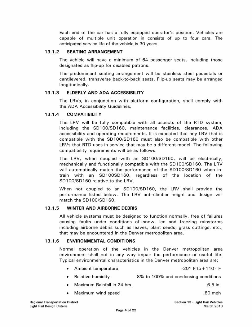
Regional Transportation District Section 13 - Light Rail Vehicles Light Rail Design Criteria March 2013
Page 4 of 22
Each end of the car has a fully equipped operator's position. Vehicles are capable of multiple unit operation in consists of up to four cars. The anticipated service life of the vehicle is 30 years.
13.1.2 SEATING ARRANGEMENT
The vehicle will have a minimum of 64 passenger seats, including those designated as flip-up for disabled patrons.
The predominant seating arrangement will be stainless steel pedestals or cantilevered, transverse back-to-back seats. Flip-up seats may be arranged longitudinally.
13.1.3 ELDERLY AND ADA ACCESSIBILITY
The LRVs, in conjunction with platform configuration, shall comply with the ADA Accessibility Guidelines.
13.1.4 COMPATIBILITY
The LRV will be fully compatible with all aspects of the RTD system, including the SD100/SD160, maintenance facilities, clearances, ADA accessibility and operating requirements. It is expected that any LRV that is compatible with the SD100/SD160 must also be compatible with other LRVs that RTD uses in service that may be a different model. The following compatibility requirements will be as follows.
The LRV, when coupled with an SD100/SD160, will be electrically, mechanically and functionally compatible with the SD100/SD160. The LRV will automatically match the performance of the SD100/SD160 when in-train with an SD100SD160, regardless of the location of the SD100/SD160 relative to the LRV.
When not coupled to an SD100/SD160, the LRV shall provide the performance listed below. The LRV anti-climber height and design will match the SD100/SD160.
13.1.5 WINTER AND AIRBORNE DEBRIS
All vehicle systems must be designed to function normally, free of failures causing faults under conditions of snow, ice and freezing rainstorms including airborne debris such as leaves, plant seeds, grass cuttings, etc., that may be encountered in the Denver metropolitan area.
13.1.6 ENVIRONMENTAL CONDITIONS
Normal operation of the vehicles in the Denver metropolitan area environment shall not in any way impair the performance or useful life. Typical environmental characteristics in the Denver metropolitan area are:
• Ambient temperature -20° F to+110° F
• Relative humidity 8% to 100% and condensing conditions
• Maximum Rainfall in 24 hrs. 6.5 in.
• Maximum wind speed 80 mph

Regional Transportation District Section 13 - Light Rail Vehicles Light Rail Design Criteria March 2013
Page 5 of 22
• Maximum snowfall in 24 hrs. 18.5 in.
• Freezing rain and ice conditions 1 time/yr.
• Elevation 6000 ft.
13.2 GENERAL VEHICLE REQUIREMENTS
13.2.1 DIMENSIONS
13.2.1.1 CARBODY DIMENSIONS
TABLE 13A – CARBODY DIMENSIONS
Maximum length of car over coupler faces 24536 mm (80.5 ft.)
Maximum width of car at widest point (excluding mirrors) 2692 mm (8.83 ft.)
Maximum roof-mounted equipment height, exclusive of pantograph, above top of rail (TOR) with new wheels and car at AWO
3810 mm (12.5 ft.)
Nominal coupler vertical centerline height above TOR, car at AWO, with new wheels
605 mm (23.82 ft. in.)
Maximum floor height above top-of-rail (AWO) 991 mm (39 in.)
Minimum interior ceiling height, finished floor to finished ceiling, on vehicle centerline, except at articulation
2032 mm (6.70 ft.)
Minimum door bottom clearance above top-of-rail (AWO) 260 mm (10.25 in.)
Minimum side door clear opening width with doors fully opened 1237 mm (48.7 in.)
Minimum clear side door height from finished floor 2007 mm (6.58 ft.)
Minimum width of cab door opening 622 mm (24.5 in.)
Minimum height of cab door opening 905 mm (6 ft. 3 in.)
Minimum double seat width 889 mm (35.0 in.)
Minimum seat to wall offset 25.4 mm (1 in.)
Minimum aisle width 660 mm (26.0 in.)

Regional Transportation District Section 13 - Light Rail Vehicles Light Rail Design Criteria March 2013
Page 6 of 22
Minimum plus seat thickness, seat pitch 762 mm (20.0 in.)
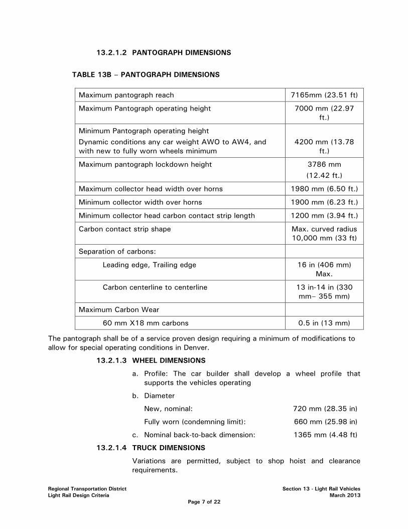
Regional Transportation District Section 13 - Light Rail Vehicles Light Rail Design Criteria March 2013
Page 7 of 22
13.2.1.2 PANTOGRAPH DIMENSIONS
TABLE 13B – PANTOGRAPH DIMENSIONS
Maximum pantograph reach 7165mm (23.51 ft)
Maximum Pantograph operating height 7000 mm (22.97 ft.)
Minimum Pantograph operating height Dynamic conditions any car weight AWO to AW4, and with new to fully worn wheels minimum
4200 mm (13.78
ft.)
Maximum pantograph lockdown height 3786 mm (12.42 ft.)
Maximum collector head width over horns 1980 mm (6.50 ft.)
Minimum collector width over horns 1900 mm (6.23 ft.)
Minimum collector head carbon contact strip length 1200 mm (3.94 ft.)
Carbon contact strip shape Max. curved radius 10,000 mm (33 ft)
Separation of carbons:
Leading edge, Trailing edge 16 in (406 mm) Max.
Carbon centerline to centerline 13 in-14 in (330 mm– 355 mm)
Maximum Carbon Wear
60 mm X18 mm carbons 0.5 in (13 mm)
The pantograph shall be of a service proven design requiring a minimum of modifications to allow for special operating conditions in Denver.
13.2.1.3 WHEEL DIMENSIONS
a. Profile: The car builder shall develop a wheel profile that supports the vehicles operating
b. Diameter
New, nominal: 720 mm (28.35 in)
Fully worn (condemning limit): 660 mm (25.98 in)
c. Nominal back-to-back dimension: 1365 mm (4.48 ft)
13.2.1.4 TRUCK DIMENSIONS
Variations are permitted, subject to shop hoist and clearance requirements.

Regional Transportation District Section 13 - Light Rail Vehicles Light Rail Design Criteria March 2013
Page 8 of 22
a. Nominal truck spacing, centerline-to-centerline:
7720 mm (25.33 ft)
13.2.2 WEIGHTS
• The AWO car weight will not exceed 1650 kg per meter of length (1106.04 Ibs/ft), measured over the coupler faces.
• The AWO car weight at the center truck is within the range of 25% to 35% of the total car weight.
• The difference in car weight between motor trucks will not exceed 900 kg (1984.2 Ibs).
• Wheel load on one side of a truck will not differ by more than 3% from the load on the opposite wheel at AWO.
13.2.3 CURVES AND GRADES
The vehicle shall operate over:
Minimum horizontal curve radius 25 m (82.0 ft)
Minimum vertical curve radius, crest 250 m (820.2 ft)
Minimum vertical curve radius, sag 350 m (1148.3 ft)
Maximum gradient 7%
13.2.4 CLEARANCES
13.2.4.1 GENERAL
Maximum normal dynamic roll angle: 2.5 degrees
Maximum dynamic role angle, failed suspension: 4 degrees
13.2.4.2 UNDERCAR CLEARANCES
Vertical undercar clearance is defined from TOR with the maximum suspension deflection and car body roll, minimum vertical curve radius and fully worn wheels.
Minimum vertical clearance under floor mounted equipment shall be 102 mm (4.0 in).
Minimum vertical clearance truck mounted equipment shall be 76 mm (3.0 in).
With the above conditions and with any radius curve, clearances between truck components and the car body shall be no less than 38 mm (1.5 in).
13.2.4.3 VEHICLE CLEARANCE ENVELOP AND STATION PLATFORM INTERFACES
The station platform interface shall be as described in Sections 4.2.4.3.b and 5.4.1.
13.2.5 CATENARY VOLTAGES
Regional Transportation District Section 13 - Light Rail Vehicles Light Rail Design Criteria March 2013
Page 9 of 22
The vehicle, and all vehicle systems, will operate normally at any catenary voltage between 525 Vdc and 925 Vdc, except where indicated otherwise.
No vehicle equipment will generate voltages in excess of 900 Vdc into the catenary system. The SD100/SD160 can operate continuously between 525 Vdc - 925 Vdc.
13.2.6 PERFORMANCE
All car systems will provide the indicated performance at all line voltage levels between 525 Vdc and 925 Vdc with the nominal voltage rating of 750 Vdc, except the braking systems, which will function at any line voltage down to 0 Vdc.
Acceleration
For vehicle loads from AWO to AW2, and all speeds from 0 to 40 km/h (25 mph), an acceleration of 1.34 m/s (3.0 mphps) will be provided. Time to reach 90 km/h (56 mph) shall be no greater than 35 seconds.
At loads above AW2, the acceleration may be reduced proportionally by the ratio of AW2 to the actual car weight.
13.2.6.1 SERVICE BRAKE REQUIREMENTS
Braking will be comprised of a combination of dynamic, regenerative and disc braking. The term "electric braking" will be used to mean dynamic and/or regenerative braking.
Braking efforts on each of the three trucks will be apportioned according to the vehicle weight distribution at each truck.
For vehicle weights up to AW2, motor truck braking will be entirely electric braking. For vehicle weights above AW2, motor truck disc braking will supplement the electric brake. Center truck braking will be via friction disc brakes.
On the motor trucks, friction braking will be automatically blended with electric braking to provide the requested effort.
For all vehicle weights from AWO to AW3 and at all speeds from 0 to 90 km/h (56 mph), an instantaneous service brake deceleration of 1.56 m /s ± 10% (3.5 mphps) will be provided. For vehicle weights above AW2, and speeds greater than 72 km/h (45 mph), electric braking may be tapered to no less than 1.0 m/s (2.2 mphps), with the remaining effort provided by motor truck friction discs.
For vehicle weights above AW3, brake rates shall be proportional to the ratio of AW3 to the actual car weight.
Electric brake fade shall not occur above 8 km/h (5 mph).
In the event of electric brake failure, maximum train speed will be automatically limited to not less than 56 km/h (25 mph). Under this restricted speed condition, the disc brakes shall be capable of

Regional Transportation District Section 13 - Light Rail Vehicles Light Rail Design Criteria March 2013
Page 10 of 22
providing the above service brake rate, with a ±20% tolerance, without damage to any equipment or brake pads.
13.2.6.3 EMERGENCY BRAKING REQUIREMENTS
For brake entry speeds equal to or greater than 50 km/h (31 mph), the minimum emergency brake rate, at all weights up to AW4, shall meet or exceed the values calculated by the following equation:
RAV =-0.006v + 2.5
Where RAV is the average emergency braking rate in m/s and v is the brake entry speed in km/h.
The maximum emergency braking rate shall not exceed the minimum rates by more than 30%.
For brake entry speeds greater than 25 km/h (15 mph) and less than 50 km/h (31 mph), the average emergency brake rate shall be a minimum of 2.2 m/s (5.0 mphps) and shall not exceed this rate by more than 30%.
For brake entry speeds of less than 25 km/h (15 mph), the instantaneous emergency brake rate after the rate has built up shall be a minimum of 2.2 m/s (5.0 mphps) and the maximum rate shall follow the characteristics of the magnetic track brake.
13.2.6.4 PARKING BRAKE
The parking brake system shall hold an AW4 vehicle on a 7% grade indefinitely.
13.2.6.5 SPEED CHARACTERISTICS
Minimum balancing speed: 90 km/h (56 mph)
(AWO to AW2, level tangent track)
Balancing speed on a 5% uphill grade: 65 km/h (40 mph)
(AWO to AW2, tangent track)
Minimum safe operating speed: 105 km/h (65 mph)
(Fully worn wheels)
The vehicle shall be capable of continuous operation at low speeds of 8 km/h (5 mph) or less. A regulated speed control shall provide a constant speed for car wash and similar activities. This function will be selectable at the master controller, and shall be initially set at 5 km/h (3 mph).
13.2.6.6 MODE CHANGE DEAD TIMES
Mode change dead times will not exceed the following:
Power to Brake 300 ms
Power to Coast 300 ms
Regional Transportation District Section 13 - Light Rail Vehicles Light Rail Design Criteria March 2013
Page 11 of 22
Coast to Brake 300 ms
Coast to Power 300 ms
Brake to Power - below 3 mph 300 ms
Brake to Power - above 3 mph 600 ms
13.2.6.7 JERK LIMITS
Changes in acceleration or deceleration shall be limited to a fixed rate of change (jerk limit) of 2.0 m/s3 +10% (4.5 mph/s2) unless the command signal changes at a lower rate.
Emergency brake applications shall not be jerk limited.
13.2.7 SPIN/SLIDE CORRECTION
A system shall be provided to detect and correct wheel spin and slide on each car whether random or synchronous on an individual truck basis both in acceleration and braking.
Efficiency shall be at least 90% in acceleration and in braking for adhesion levels above 5%.
13.2.8 NO-MOTION DETECTION
Apparatus shall be provided to detect all vehicle motions down to and including 3 km/h (1.9 mph).
13.2.9 DUTY CYCLE RATING
The car shall be capable of continuous operation on any of RTD lines without exceeding the continuous rating of any equipment, under the following conditions:
• A constant AW2 load
• A dwell time of 10.0 seconds at each stop
• Acceleration and braking at maximum rates
• Operation to maximum track speeds
• A 30 second layover at each end of the line
In addition, one train with an AW3 load shall be capable of pushing or towing another train of equal length with an AW3 load from the point of failure to the next station, where passengers would be unloaded, and then continue with both trains at AWO load to the end of the line, at reduced performance, without damage or reduction in equipment life. The point of failure shall be considered to be at the farthest location on the line from either end of the line such that the worst load is imposed on the equipment. The train will be dispatched to the nearest end of the line. The train operating in this condition would be operated as a special equipment movement with no passenger station stops after the first and would slow
Regional Transportation District Section 13 - Light Rail Vehicles Light Rail Design Criteria March 2013
Page 12 of 22
down only as normally required by other traffic, signals, and civil requirements. Maximum speed may be reduced, by rulebook, to not less than 30 mph.
13.2.10 ELECTROMAGNETIC EMISSIONS
The vehicle will not produce disruptive electrical interference affecting its own equipment, existing or proposed RTD wayside equipment or other LRVs.
13.2.10.1 RADIATED EMISSION LIMITS
• From 0.01 MHZ to 30 MHZ, the maximum permissible interference limit shall not exceed 20 dB above the limit of Figure 22 (RE05) of MIL-STD-461 A.
• From 30 MHZ to 88 MHZ, the maximum permissible interference limit shall be 58 dB above one p,V/m/MHZ bandwidth.
• From 88 MHZ to 1000 MHZ, the maximum permissible interference limit shall be 68 dB above one p,V/m/MHZ bandwidth.
13.2.10.2 CONDUCTIVE EMISSION LIMITS
• From 0 Hz to 40 Hz, 10 A maximum.
• From 40 Hz to 120 Hz, 1 A maximum.
• From 120 Hz to 320 Hz, 10 A maximum.
• Above 320 Hz, the emissions limit then follows a smooth curve through 10 A at 320 Hz, 0.08 A at 2 kHz, 0.016 A at 4 kHz and 0.0046 A at 7 kHz.
13.2.10.3 INDUCTIVE EMISSION LIMITS
The inductive emissions shall be limited to a maximum of 20 millivolts, rms, rail-to-rail, at all frequencies between 20 Hz and 20 kHz.
13.2.11 NOISE
Interior noise shall not exceed the following:
• Vehicle stationary: 70 dBA
Windows and doors closed, all auxiliaries operating simultaneously under normal operating conditions
• Vehicle operating: 75 dBA
Car operating on any line at any speed except in tunnels
Exterior noise, measured 15 m (49.21 ft) from the centerline of the track, 1.5 m (4.92 ft) above the ground, shall not exceed the following:

Regional Transportation District Section 13 - Light Rail Vehicles Light Rail Design Criteria March 2013
Page 13 of 22
• Vehicle stationary: 65 dBA
• Vehicle operating on tangent track: 75 dBA
13.2.12 SHOCK AND VIBRATION
Vibrations anywhere on the vehicle floor, walls, ceiling panels and seat frames shall not exceed the following:
• Below 1.4 Hz: Maximum deflection (peak to peak): 2.5 mm
• 1.4hz to 20 Hz: Peak acceleration: 0.01 g
• Above 20 Hz: Peak velocity: C
All vehicle equipment shall withstand the following:
• Car-body-mounted components: o Vibrations up to 0.4g peak to peak, at frequencies up
to 100 Hz o Impact loads of 2g lateral, 3g vertical and 5g
longitudinal
• Truck-frame-mounted components: o Vibrations up to 4g peak to peak at frequencies up to
100 Hz o Impact loads up to 20g each applied individually on any
major axis
• Truck-axle-mounted components: o Vibrations up to 10g peak to peak at frequencies up to
100 Hz o Impact loads up to 50g each applied individually on any
major axis
13.2.13 RIDE QUALITY
The rms acceleration values shall not exceed the "4-hour, reduced comfort level (vertical)" and "2.5 hr, reduced comfort level (horizontal)" boundaries derived from Figure 2a (vertical) and Figure 3a (horizontal) of ISO 2631 over the range of 1 Hz to 80 Hz, for all load conditions AWO to AW3.
13.2.14 FLAMMABILITY AND SMOKE EMISSIONS
All materials used in the construction of the car shall meet the requirements of NFPA 130 Sections 4.1, 5.2, 5.4 and 5.6.
The floor structural assembly shall meet a 30-minute minimum endurance rating if tested in accordance with ASTM E 119. The ceiling structural assembly shall meet a 15-minute minimum endurance rating if tested in accordance with ASTM E 119.
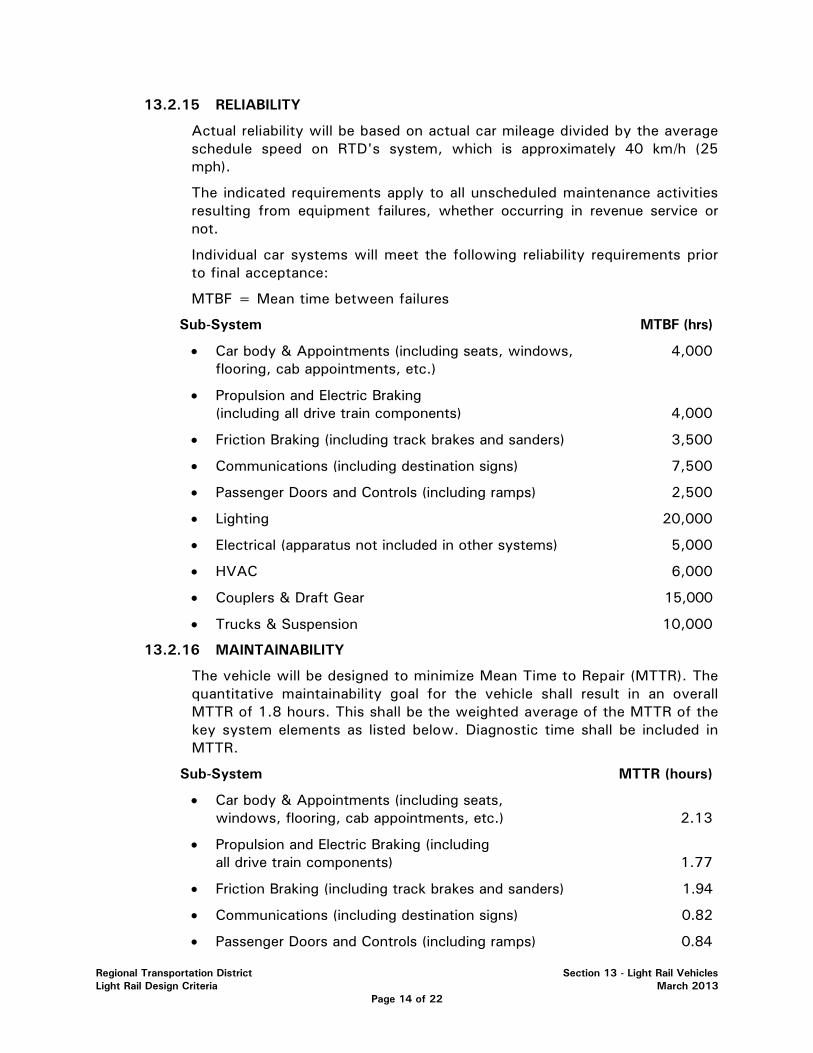
Regional Transportation District Section 13 - Light Rail Vehicles Light Rail Design Criteria March 2013
Page 14 of 22
13.2.15 RELIABILITY
Actual reliability will be based on actual car mileage divided by the average schedule speed on RTD's system, which is approximately 40 km/h (25 mph).
The indicated requirements apply to all unscheduled maintenance activities resulting from equipment failures, whether occurring in revenue service or not.
Individual car systems will meet the following reliability requirements prior to final acceptance:
MTBF = Mean time between failures
Sub-System MTBF (hrs)
• Car body & Appointments (including seats, windows, 4,000 flooring, cab appointments, etc.)
• Propulsion and Electric Braking (including all drive train components) 4,000
• Friction Braking (including track brakes and sanders) 3,500
• Communications (including destination signs) 7,500
• Passenger Doors and Controls (including ramps) 2,500
• Lighting 20,000
• Electrical (apparatus not included in other systems) 5,000
• HVAC 6,000
• Couplers & Draft Gear 15,000
• Trucks & Suspension 10,000
13.2.16 MAINTAINABILITY
The vehicle will be designed to minimize Mean Time to Repair (MTTR). The quantitative maintainability goal for the vehicle shall result in an overall MTTR of 1.8 hours. This shall be the weighted average of the MTTR of the key system elements as listed below. Diagnostic time shall be included in MTTR.
Sub-System MTTR (hours)
• Car body & Appointments (including seats, windows, flooring, cab appointments, etc.) 2.13
• Propulsion and Electric Braking (including all drive train components) 1.77
• Friction Braking (including track brakes and sanders) 1.94
• Communications (including destination signs) 0.82
• Passenger Doors and Controls (including ramps) 0.84

Regional Transportation District Section 13 - Light Rail Vehicles Light Rail Design Criteria March 2013
Page 15 of 22
• Lighting 0.50
• Electrical (apparatus not included in other systems) 1.50
• HVAC 2.12
• Couplers & Draft Gear 1.50
• Trucks & Suspension 1.57
13.3 CAR STRUCTURE AND INTERIOR
The primary car structural material will be low-alloy, high-tensile (LAHT) steel.
The structure will withstand a 2g load applied longitudinally at the anticlimber without permanent deformation. Collision posts and similar structures above the floor will resist penetration by objects impacting above the anti-climber.
13.3.1 SEATS
Seats will be of two varieties: lateral fixed 2 person seats, or flip-up 2 person seats arranged laterally or longitudinally.
All seat frame materials visible to the public will be brushed stainless steel. Non-visible frame materials may be painted mild steel.
Seat cushions will be replaceable insert type.
13.3.2 WHEEL CHAIR ACCOMMODATIONS
Wheel chair accommodations will be provided in accordance with ADA Accessibility Guidelines.
Space for a minimum of two wheelchairs shall be allocated near the operators cab. A stop request tape switch shall be located in this area.
Passenger seats at designated wheelchair areas shall be flip-up type.
13.3.3 ELDERLY AND ADA ACCESSIBLE RAMPS
Each front doorway, nearest the operators cab, will be fitted with a manually operated ramp and bridge plate.
When deployed, the ramps will completely cover the step well, and the bridge plate will rest on the wayside platform.
The status of the ramp will be indicated by limit switch to other vehicle systems.
13.3.4 WINDOWS
The windshield will be one piece laminated clear safety glass meeting FRA Type 1 requirements.
The passenger and door windows will be laminated, tinted, safety glass meeting ANSI Type 1 requirements.
The passenger side windows will be one piece without an openable portion.
Regional Transportation District Section 13 - Light Rail Vehicles Light Rail Design Criteria March 2013
Page 16 of 22
13.4 COUPLER
The coupler will be an automatic, tight-lock, electrical coupler, which is mechanically and electrically compatible with the existing Scharfenburg/Voith coupler.
The coupler will employ an energy absorption feature that will absorb kinetic energy and prevent car structure damage until the anti-climbers mate.
13.5 OPERATOR'S CAB
The general arrangement of the operator's cab shall be similar to the SD100/SD160 cab, with changes and improvements as noted.
• All cab features will be located and dimensioned to accommodate RTD operators in the size range of the 5th to 95th percentile of U.S. males and females.
• The operator's seat will be fully adjustable via electric or manual controls and will be the exact model and Brand (currently USSC, model 9002) as the current seats in the SD100/SD160 cabs.
• Each sidewall of the cab will include a sliding window providing easy access to the rearview mirror. Adjustable shades will be provided for the windshield and both side windows.
• A dual glass, electrically or manually adjustable, heated mirror will be provided on each side of the cab, viewable through the side windows. Each glass of the mirror will be independently adjustable.
13.6 PASSENGER DOORS
The door system shall be plug doors similar in configuration to the SD160 doors. Door operators will be electric.
Each door will include a dedicated, microprocessor-based, controller. The controller will respond to external commands, monitor door positions and status, and provide diagnostic and status information to portable test units (PTUs). Basic door operating parameters will be adjusted via the PTU.
Front doors will be operable independently of the other side doors for ADA accessibility.
All door control units will be linked together with a serial data connection such that the status of all doors may be monitored at a single location in the vehicle.
13.7 HEATING VENTILATION AND AIR CONDITIONING (HVAC)
Each car half will include a separate, unitized, roof-mounted HVAC unit. Each HVAC unit will function independently of the other, including logic and thermostat controls.
Compressor fluid will be 407c or an RTD approved equivalent.
The vehicle will include floor heaters to supplement the heat provided by the HVAC units.
13.8 LIGHTING
All vehicle lighting will operate from the car's LVPS.
Except for interior passenger lighting, headlights, roof lamps and cab ceiling lights, all lights shall be LED based.
Regional Transportation District Section 13 - Light Rail Vehicles Light Rail Design Criteria March 2013
Page 17 of 22
Interior passenger lighting will be via two continuous rows of fluorescent light fixtures along the length of the passenger compartment, except in the articulation. Illumination levels at 840 mm above the floor at any seat will be 375 lux, minimum. Illumination levels on the floor anywhere in the vehicle will be 215 lux, minimum. High-frequency inverter ballasts will power the fluorescent fixtures.
The fluorescent fixture adjacent to each doorway, as well as other specified light fixtures, will be powered directly from the battery to provide emergency lighting during LVPS failure.
13.9 ELECTRICAL
13.9.1 TRANSIENTS
A roof-mounted MOV-type lightning arrester will provide over-voltage protection meeting minimum IEC 1287-1 requirements.
All vehicle equipment will be protected against transient voltages whether generated externally or internally, independent of the lightning arrester.
All equipment capable of generating electrical transients will include suppression devices.
13.9.2 AUXILIARY POWER SUPPLY
Low Voltage Power System: 28 Vdc
AC Power Supply: 208/120 Vac RMS, 3 phase, 4 wire, 60 Hz.
The vehicle will provide 3-phase 208 Vac power from a static inverter operated from the catenary. Low voltage DC circuits will operate at 28 Vdc, provided by a static converter (LVPS) operated from the catenary. The LVPS and AC inverter may share enclosures, but will have limited common components.
The LVPS will also provide battery charging.
13.9.3 BATTERY
A 20-cell, nickel cadmium battery will provide back-up low voltage power in the event of LVPS failure. The battery will be sized to carry emergency loads for 1 hour.
13.9.4 MISCELLANEOUS
A pantograph will be provided on each vehicle, mounted such that the head is located over the center truck.
HV circuit protection will be provided by roof-mounted high-speed circuit breaker (HSCB). All other high voltage circuits will be protected by fuses mounted beneath the floor, except as noted below.
Provision will be included to reset the HSCB with a discharged battery. For this purpose, a roof-mounted fuse may provide HV to the inverter/LVPS.
All non-HV circuits will be protected by circuit breakers. All motors on the vehicle will be 3-phase, AC motors.

Regional Transportation District Section 13 - Light Rail Vehicles Light Rail Design Criteria March 2013
Page 18 of 22
The quantity of commands and indications for the LRV are expected to exceed the spare pin count on the SD100. As such, many commands and indications not common with the SD100 will be carried via serial and/or multiplexed signals on SD100 spare trainlines.
13.10 PROPULSION/ELECTRIC BRAKES
The propulsion equipment will be configured as two independent IGBT-based inverter system, one for each motor truck.
Motortrucks will be configured as bi-motor, parallel drive. Traction motors will be self-ventilated squirrel cage AC motors designed and tested to IEEE Standards 11 and 112, or IEC 349-2. Traction motors will be configured as TEFC or WP Type 1 per NEMA MG1.
The propulsion equipment will provide electric brake effort signals to the friction brake system for blending. The propulsion equipment will provide spin/slide control independent of the friction brake system.
Each propulsion inverter will include a line filter and line contactor for EMI control and isolation from the catenary, respectively. The line contactors will open during emergency braking. The propulsion equipment will provide regenerative braking whenever the overhead catenary is receptive. In the case when the overhead catenary is not receptive to regenerative braking, the rheostatic braking resistors shall be capable of handling 100% of the load without damage.
13.11 TRUCKS
Trucks will be of proven design, and may be inboard or outboard bearing. Suspension components will be selected to provide a stable and comfortable ride at all vehicle speeds without excessive track or wheel wear.
Primary suspension will be coil spring or rubber elements. Secondary suspension will be coil spring.
Each of the three trucks will provide a load signal to the propulsion and braking systems. Load leveling will not be provided.
Wheels will be resilient types, Bochum 84, with external shunts.
Provision for floor height adjustment to compensate for wheel wear and suspension variation will be provided on each truck.
13.12 FRICTION BRAKE
The friction brake equipment will be comprised of hydraulic disc brakes, track brakes and sanders.
Hydraulic disc brakes will be provided on each axle of each truck. The size and quantity of each axle’s discs will be selected to provide the thermal capacity as defined by the performance requirements. A dedicated hydraulic power unit, each with a dedicated electronic controller, will independently control each truck's disc brakes.
Each electronic control will independently monitor trainlined input commands and local vehicle conditions, as well as the status of its own components, and provide diagnostic and status outputs to a PTU.
Regional Transportation District Section 13 - Light Rail Vehicles Light Rail Design Criteria March 2013
Page 19 of 22
Each truck will be provided with two track brakes.
Each motor truck will be provided with sand nozzles for each wheel, with controls arranged to deposit sand only in front of the leading axle of each motor truck.
13.13 COMMUNICATIONS
The LRV communication equipment will be comprised of on board train radios, public address (PA) and passenger emergency intercom (PEI). It shall function with a passenger information system, which includes all signs and communication systems. Closed Circuit Television (CCTV) equipment shall also be provided for LRV interior video surveillance with wireless download capability to wayside access points.
Radios will be commercial units functionally compatible with the existing RTD radio system, and integrated into the cab console.
The public address system will allow one-way communication between the operator and passengers via the interior and or exterior speakers.
A passenger emergency intercom system will allow two-way communication between individual passengers and the operator. Each vehicle will have 2 intercom stations. A passenger will hail the operator by pressing a button on the station, which sounds a tone in the cab. The operator establishes, and controls, the communication link.
The Automatic Announcement System (AAS) will control all pre-recorded audible announcements. The audio messages will be stored in digital form, and played over the PA system. All functions of the AAS will be trainline. AAS with be capable of automatic initialization to produce the correct announcement for the related location or station prior to entering a station and in a station.
The PA and AAS will be configured as two independent systems, each system will have a dedicated amplifier.
Destination or route designations will be displayed on the end and side signs. The end and side destination signs will be LED or LCD. The operator will enter the route into a control head via a route ID number. The route ID will determine the sequencing of messages, or other information entered by the train operator.
A Central Control Unit (CCU) will control all portions of the communication system, except for train radio. The train radio will interface with the CCU but in the event of CCU failure the radio will remain functioning.
13.14 TWC, ATS AND EVENT RECORDER
This section establishes the requirements for the vehicle Train-to-Wayside Communications (TWC) system, Automatic Train Stop (ATS) system and Event Recorder. The Contractor shall furnish and install all carborne TWC, ATS, and event recorder equipment as described in the following sections. The TWC, ATS and event recorder systems shall be service proven and compatible with RTD's present equipment and operations.
13.14.1 TRAIN TO WAYSIDE
The vehicle shall be equipped with a TWC system that is the same or compatible with the Hanning and Kahl (H&K) and VECOM USA, LLC TWC system. The TWC transponders mounted at both ends on the center line of
Regional Transportation District Section 13 - Light Rail Vehicles Light Rail Design Criteria March 2013
Page 20 of 22
the carbody, approximately 10 feet from the end of the coupler. The TWC system uses a wayside interrogator to excite a wayside loop antenna with approximately 0.1 A, at frequencies between 80 kHz. and 120 kHz.
The TWC system shall be configurable or support unlimited message data transfer, bi-directional communication and error detection and correction capability.
The Vehicle TWC equipment shall be furnished and installed to provide for the accurate transmission of a 19-bit data message from the carborne transponders. The wayside interrogator shall process the following information from the LRVs via the wayside loop antennas:
Active cab:
• Train Number (00-99) 7 bits
• Route Number (00-99) 7 bits
• Stationary Pre-empt/Activation button in cab 1 bit
• Cancel (route) button in cab 1 bit
• Spare 3 bits Intermediate (inactive) cabs (for multiple-unit consists only):
• Car Number (000-999) 10 bits
• Active Cab (off for intermediate cab) 1 bit
• End-of-train (off for intermediate cab) 1 bit
• Spare 7 bits Trailing (rear-end, end-of-train, inactive) cab:
• Car Number (000-999) 10 bits
• Active Cab (off for trailing cab) 1 bit
• End-of-train (on for trailing cab) 1 bit
• Spare 7 bits
13.14.2 AUTOMATIC TRAIN STOP
Each cab of each LRV shall be equipped with a service proven Automatic Train Stop (ATS) System which shall automatically place the car into an irretrievable braking mode should the Train Operator attempt to pass a red wayside signal. The ATS system consists of both, carborne receiving and control equipment and wayside transmitting equipment. The carborne portion shall consist of two receiving magnets, two car-switching (control) units, a cab control panel in each cab and the necessary brake interface while the wayside portion consists of a transmitting magnet.
The carborne ATS equipment shall function with the existing wayside ATS equipment on the RTD LRT system including the Stop and Proceed functionality.
Vehicle ATS equipment shall be installed to be effective only in the normal direction of traffic on a given track and not be effective for reverse movement. The ATS equipment shall be interconnected with the car

Regional Transportation District Section 13 - Light Rail Vehicles Light Rail Design Criteria March 2013
Page 21 of 22
propulsion equipment and braking systems such that only the ATS equipment associated with the active cab of a car shall be activated in the direction of forward travel. The ATS system shall not be functional when a car is operated in the reverse direction of travel from a given cab.
Each cab shall be equipped with the following ATS control equipment:
• "ATS Bypass" indicator lamp
• "ATS Trip" indicator lamp
• "ATS Reset" switch
• "ATS Key-By" switch
13.14.3 EVENT RECORDER
Each LRV shall be provided with a service proven, fully electronic data recorder system, which shall store times, speeds, distances traveled and both analog and digital events as described further below. The event recorder shall be a self-contained unit with data storage and retrieval capabilities. Unless explicitly stated otherwise, the event recorder shall comply with the requirements of IEEE 1482.1, "Standard for Rail Transit Vehicle Event Recorders."
13.15 MATERIALS AND WORKMANSHIP
All equipment employed in the construction of these LRVs shall be designed and manufactured to recognized U.S. or international standards for heavy industrial applications. Material and workmanship shall be in accordance with the stated specification or description, unless written approval for substitution is obtained.
13.16 TESTING
The complete car and its apparatus shall undergo a comprehensive test program to substantiate required design and performance characteristics. The contractors test plans, procedures and reports are subject to review and approval by RTD. Comprehensive design conformance, production conformance and routine acceptance tests and test procedures are required.
13.17 QUALITY ASSURANCE
The Contractor shall plan, establish and maintain a quality assurance program. The elements of the Contractor's quality assurance program shall be required of all entities within the Contractor’s organization and all subcontractors.
13.18 TECHNICAL PUBLICATION AND USER EDUCATION
Manuals, integrated schematics, narratives and training are to be provided under the particular LRVs contract. They shall include but not limited to:
• Operating Manuals
• Running Maintenance and Servicing Manuals
• Heavy Repair Maintenance Manuals
• Integrated Schematics and Narratives
• Tools and Test Equipment Maintenance Manuals

Regional Transportation District Section 13 - Light Rail Vehicles Light Rail Design Criteria March 2013
Page 22 of 22
• Illustrated Parts Catalogs
Electronic versions and licenses of all manuals will be provided to the RTD.
For the life of the vehicle, the manufacturer will provide updates and corrections of the manuals to the RTD to match the vehicle system’s detail.
Electronic versions of the manuals and schematics will use software that can be changed and updated by the customer. These changes or additions will be submitted to the manufacturer and will be incorporated by the manufacturer into latest master document maintained and distributed by the manufacturer.
Durable "oil proof" pages and binders shall be required per RTD's requirements.
13.19 SUPPORT EQUIPMENT
The Contractor shall provide all support equipment necessary for maintaining, troubleshooting, testing, repairing, calibrating and inspecting all carborne equipment. This shall include equipment for the support of shop repair and overhaul activities, for on-board inspection and testing and for maintaining and updating all deliverables.
• Common Tools
• Gauges and Special Tools
• Portable Test Equipment
• Bench Test Equipment
• Repair Data
• Workstations
• Bar Coding Equipment
• Spare Parts
Regional Transportation District Section 14 – System Safety and System Security Light Rail Design Criteria March 2013
Page 1 of 28
SECTION 14 – SYSTEM SAFETY AND SYSTEM SECURITY
14.1 GENERAL ................................................................................................. 2
14.2 APPLICABLE STANDARDS ......................................................................... 3
14.3 DEFINITION OF SAFETY CONDITIONS ......................................................... 5 14.3.1 UNACCEPTABLE CONDITIONS..........................................................5 14.3.2 ACCEPTABLE CONDITIONS..............................................................6
14.4 HAZARD IDENTIFICATION, ANALYSIS, AND RESOLUTION ............................. 7
14.5 PRELIMINARY HAZARD ANALYSIS (PHA) ..................................................... 8
14.6 SAFETY CERTIFICATION ............................................................................ 8
14.7 RIGHT-OF-WAY FENCING AND BARRIERS .................................................. 11
14.8 EMERGENCY ACCESS/EGRESS, STATION DESIGN, AND WALKWAYS ........... 13
14.9 GRADE CROSSINGS ................................................................................ 14
14.10 VIDEO SURVEILLANCE ............................................................................ 15
14.11 EMERGENCY TELEPHONES ...................................................................... 19
14.12 CRIME PREVENTION THROUGH ENVIRONMENTAL DESIGN .......................... 20
14.13 THREAT AND VULNERABILITY ANALYSIS AND RESOLUTION.......................21
14.13.1 SEVERITYCATEGORIES.............................................................21 14.13.2 TRANSIT RISKASSESSMENT LEVEL.............................................21 14.13.3 PROBABILITY CATEGORIES........................................................22
14.14 PARK-N-RIDES, PARKING STRUCTURES, AND ENCLOSED UNDERGROUND OR
BELOW GRADE TRANSIT FACILITIES..........................................................25 14.14.1 SURFACE PARK-N-RIDES.........................................................25 14.14.2 PARKING STRUCTURES..........................................................26 14.14.3 UNDERGROUND AND BELOW GRADE TRANSIT FACILITIES..........26
14.15 PUBLICLY ACCESSIBLE RECEPTACLES ..................................................... 27
14.16 CONFIGURATION MANAGEMENT ............................................................ 28

Regional Transportation District Section 14 – System Safety and System Security Light Rail Design Criteria March 2013
Page 2 of 28
SECTION 14 – SYSTEM SAFETY AND SYSTEM SECURITY
14.1 GENERAL
The LRT design shall address system elements according to the requirements of the applicable standards listed. Should any standard or requirement conflict, the most stringent standard shall apply. In accordance with RTD’s System Safety and System Security Program Plan, RTD’s Executive Safety and Security Committee must review and accept all LRT design and any subsequent changes or modifications. The RTD Project Manager and/or Design Engineer shall present design reviews to the RTD Executive Safety and Security Committee for acceptance as design milestones are reached. Additionally, any level 4 variance request from RTD’s design criteria, (a variance request that exceeds the maximum allowable criteria), must be approved by RTD’s Executive Safety and Security Committee.
Standards, specifications, regulations, design handbooks, safety design checklists and other sources of design guidance will be reviewed for pertinent safety design requirements applicable to the system. The design shall establish criteria derived from all applicable information. Some general system safety design requirements are:
• Identified hazards shall be eliminated or associated risk shall be reduced through design, including material selection or substitution. When potentially hazardous materials must be used, such materials selected shall pose the least risk throughout the life cycle of the system.
• Hazardous substances, components and operations shall be isolated from other activities, areas, personnel and incompatible materials.
• Equipment shall be located so that access during operations, servicing, maintenance, repair or adjustment minimizes personnel exposure to hazards (e.g. hazardous chemicals, high voltage, electromagnetic radiation, cutting edges or sharp points).
• Risk resulting from excessive environmental conditions (e.g. temperature, pressure, noise, toxicity, acceleration and vibration) shall be minimized.
• Risk resulting from human error in system operation and support shall be minimized as part of the design effort.
• In the case of risk from hazards that cannot be eliminated, alternatives that will minimize such risk shall be considered. (E.g. interlocks, redundancy, fail safe design, system protection, fire suppression and other protective measures, such as clothing, equipment, devices and procedures.)
• Power sources, controls and critical components of redundant subsystems shall be protected by physical separation or shielding, or by other suitable methods mutually agreeable to the design and RTD.
• When alternate design approaches cannot eliminate the hazard, safety and warning devices and warning and cautionary notes shall be provided in assembly, operations, maintenance and repair instructions, and distinctive markings shall be provided on hazardous components, equipment and facilities to ensure personnel and equipment protection. These shall be standardized in accordance with
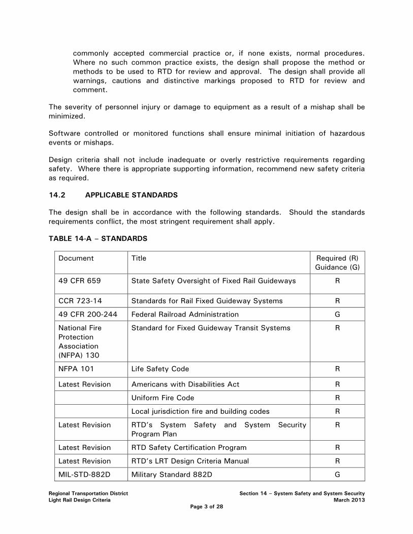
Regional Transportation District Section 14 – System Safety and System Security Light Rail Design Criteria March 2013
Page 3 of 28
commonly accepted commercial practice or, if none exists, normal procedures. Where no such common practice exists, the design shall propose the method or methods to be used to RTD for review and approval. The design shall provide all warnings, cautions and distinctive markings proposed to RTD for review and comment.
The severity of personnel injury or damage to equipment as a result of a mishap shall be minimized.
Software controlled or monitored functions shall ensure minimal initiation of hazardous events or mishaps.
Design criteria shall not include inadequate or overly restrictive requirements regarding safety. Where there is appropriate supporting information, recommend new safety criteria as required.
14.2 APPLICABLE STANDARDS
The design shall be in accordance with the following standards. Should the standards requirements conflict, the most stringent requirement shall apply.
TABLE 14-A – STANDARDS
Document Title Required (R) Guidance (G)
49 CFR 659 State Safety Oversight of Fixed Rail Guideways R
CCR 723-14 Standards for Rail Fixed Guideway Systems R
49 CFR 200-244 Federal Railroad Administration G
National Fire Protection Association (NFPA) 130
Standard for Fixed Guideway Transit Systems R
NFPA 101 Life Safety Code R
Latest Revision Americans with Disabilities Act R
Uniform Fire Code R
Local jurisdiction fire and building codes R
Latest Revision RTD’s System Safety and System Security Program Plan
R
Latest Revision RTD Safety Certification Program R
Latest Revision RTD’s LRT Design Criteria Manual R
MIL-STD-882D Military Standard 882D G

Regional Transportation District Section 14 – System Safety and System Security Light Rail Design Criteria March 2013
Page 4 of 28
Document Title Required (R) Guidance (G)
NFPA 70 National Electric Safety Code
R
U.S. Department of Transportation (DOT), FTA, latest revision
Transit Threat Level Response Recommendation G
U.S. Department of Transportation (DOT), FTA, November 2002
Handbook for Transit Safety and Security Certification
R
U.S. Department of Transportation (DOT), January 2000
Hazard Analysis Guidelines for Transit Projects
G
U.S. Department of Transportation (DOT), FRA
FRA “Collision Hazard Analysis Guide: Commuter and Intercity Passenger Rail Service”, October 2007
G
29CFR1910 Federal Occupational Safety and Health Standards (General Industry)
R
29CFR1926 Federal Occupational Safety and Health Standards (Construction Industry)
R
Transit Cooperative Research Program (TCRP) Report 17
Integration of Light Rail transit into City Streets G
Transit Cooperative Research Program (TCRP) Synthesis 79
Light Rail Vehicle Collisions with Vehicles at Signalized Intersections
G
MIL-STD-1472D Human Engineering Design Criteria for Military Systems, Equipment and Facilities
G
U.S. Department of Transportation (DOT), November 2004
Transit Security Design Considerations R
APTA SS-SIS-RP-001-08, latest
Recommended Practice for Trash/Recycling Container Placement to Mitigate the Effects of an
R

Regional Transportation District Section 14 – System Safety and System Security Light Rail Design Criteria March 2013
Page 5 of 28
Document Title Required (R) Guidance (G)
revision Explosive Event
APTA SS-SIS-RP-002-08, latest revision
Recommended Practice for CCTV Camera Coverage and Field of View Criteria for Passenger Facilities
R
14.3 DEFINITION OF SAFETY CONDITIONS
14.3.1 UNACCEPTABLE CONDITIONS
The following safety critical conditions are considered unacceptable. Positive action and implementation verification is required to reduce the risk to an acceptable level.
• Single component failure, common mode failure, human error or design features, which could cause a mishap of catastrophic or critical severity.
• Dual independent component failures, dual human errors or a combination of a component failure and a human error involving safety critical command and control functions, which could cause a mishap of catastrophic or critical severity.
• Generation of hazardous ionizing/non-ionizing radiation or energy when no provisions have been made to protect personnel or sensitive subsystems from damage or adverse effects.
• Packaging or handling procedures and characteristics which could cause a mishap for which no controls have been provided to protect personnel or sensitive equipment.
• Hazard level categories that are specified as unacceptable.
Unacceptable hazardous conditions will be identified according to the hazard resolution matrix. Hazard classification at this level is a formal process for determining which hazards are acceptable, acceptable with review by management staff, undesirable or unacceptable. Hazard severity is a subjective measure of the worst credible mishap resulting from personnel error, environmental conditions, design inadequacies and/or procedural efficiencies for system, subsystem or component failure or malfunction. Hazard probability is defined as the probability that a specific hazard will occur during the planned life expectancy of the system element, subsystem or component. The categories of hazard severity, hazard probability and their definitions follow:
Hazard Severity Definition
• Catastrophic – Death or system loss

Regional Transportation District Section 14 – System Safety and System Security Light Rail Design Criteria March 2013
Page 6 of 28
• Critical – Severe injury, severe occupational illness or major system damage
• Marginal – Minor injury, minor occupational illness or minor system damage
• Negligible – Less then minor injury, occupational illness or system damage
Hazard Probability Definition
• Frequent − Likely to occur frequently; continuously experienced
• Probable − Will occur several times in the life of an item; will occur frequently in fleet/inventory
• Occasional − Likely to occur sometime in the life of an item; will occur several times in fleet inventory
• Remote − Unlikely but possible to occur in the life of an item; unlikely but can be expected to occur in fleet/inventory
• Improbable − So unlikely, it can be assumed occurrence may not be experienced; unlikely to occur, but possible in fleet
The following table (of the RTD System Safety and System Security Program Plan) demonstrates the relationship between severity and probability to define an unacceptable hazardous condition.
TABLE 14-B – HAZARD RESOLUTION MATRIX
Catastrophic (I)
Critical (II)
Marginal (III)
Negligible (IV)
Frequent (A) Unacceptable Unacceptable Unacceptable Acceptable/
WR
Probable (B) Unacceptable Unacceptable Undesirable Acceptable/
WR
Occasional (C)
Unacceptable Undesirable Undesirable Acceptable
Remote (D) Undesirable Undesirable Acceptable/
WR Acceptable
Improbable (E)
Acceptable/WR
Acceptable/WR
Acceptable/WR
Acceptable
Acceptable/WR means acceptable with management review.
14.3.2 ACCEPTABLE CONDITIONS
The following approaches are considered acceptable for correcting unacceptable conditions and will require no further analysis once controlling
Regional Transportation District Section 14 – System Safety and System Security Light Rail Design Criteria March 2013
Page 7 of 28
actions are implemented and verified.
• For non-safety critical command and control functions; a system design that requires two or more independent human errors, or that requires two or more independent failures, or a combination of independent failure and human error.
• For safety critical command and control functions; a system design that requires at least three independent failures, or three human errors or a combination of three independent failures and human errors.
• System designs which positively prevent errors in assembly, installation or connections which could result in a mishap.
• System designs, which positively prevent damage propagation from one component to another or prevent sufficient energy propagation to cause a mishap.
• System design limitations on operation, interaction or sequencing that preclude occurrence of a mishap.
• System designs that provide an approved safety factor or fixed design allowance which limit, to an acceptable level, possibilities of structural failure or release of energy sufficient to cause a mishap.
• System designs that control energy build-up which could potentially cause a mishap (fuses, relief valves, electrical explosion proofing, etc.).
• System designs in which component failure can be temporarily tolerated because of residual strength or alternate operating paths so that operations can continue with a reduced but acceptable safety margin.
• System designs that positively alert the controlling personnel to a hazardous situation for which the capability for operator reaction has been provided.
• System designs which limit/control the use of hazardous materials.
14.4 HAZARD IDENTIFICATION, ANALYSIS, AND RESOLUTION
The Design Engineer shall develop and implement a Hazard Identification, Analysis, and Resolution process in accordance with the minimum criteria outlined in this section and 49 CFR 659. The purpose of hazard analysis and resolution during the design and engineering phase of the project is several fold: to minimize or eliminate potential hazards; support early hazard identification; integrate safe operating procedures into system design and service; and provide for constant and continuous safety evaluation and assessment.
The Design Engineer shall use the information established in the following documents:
• 49 CFR 659 using the APTA Guideline’s Hazard Resolution Matrix (American Public Transit Association, Manual for the Development of Rail Transit System Safety Program Plans, Checklist Number 7);

Regional Transportation District Section 14 – System Safety and System Security Light Rail Design Criteria March 2013
Page 8 of 28
• Military Standard 882D (MIL-STD-882D); and
• Hazard Analysis Guidelines for Transit Projects, January 2000, U.S. Department of Transportation.
Subsequent to performing the initial hazard analysis, the Design Engineer shall recommend resolution or mitigation factors to reduce the classification of identified hazards and reclassify identified hazards considering the recommended resolution.
In applying resolution to identified hazards, the Design Engineer shall utilize the following system safety precedence:
• design for minimum risk;
• incorporate safety devices;
• provide warning devices; and
• Develop procedures and training.
14.5 PRELIMINARY HAZARD ANALYSIS (PHA)
The Design Engineer shall conduct a PHA process for the project design. PHA work shall begin upon project initiation and continue throughout the project. The Design Engineer shall provide PHA progress reports according to a mutually agreeable schedule. The Design Engineer shall provide a draft and final PHA report on the preliminary engineering. Subsequent to the preliminary engineering, the Design Engineer shall conduct a draft and final PHA report on the final design.
The PHA document itself is a living document, which must be revised and updated as the system design and development progresses. It becomes the input document and information for all other hazard analyses performed on the system.
14.6 SAFETY AND SECURITY CERTIFICATION
The Design Engineer shall prepare and submit a draft and final Safety and Security Certification Plan (SSCP) in accordance with FTA Handbook for Transit Safety and Security Certification. The Design Engineer shall develop a preliminary list of safety and security certifiable items and associated design requirements based on the preliminary engineering. The safety and security certification process shall apply to all elements of the system. Separate programs shall be developed, for light rail, for commuter rail and for BRT, as appropriate.
The Design Engineer shall identify those system elements and design standards to comply with the major steps in the safety certification process. These steps are implemented beginning with system design and continue through the start of revenue operation.
• Define and identify those safety-critical system elements to be certified.
• Define and identify those security-related elements to be certified.
• Define and develop a Certifiable Items List (CIL).
• Identify safety and security requirements for each certifiable item.
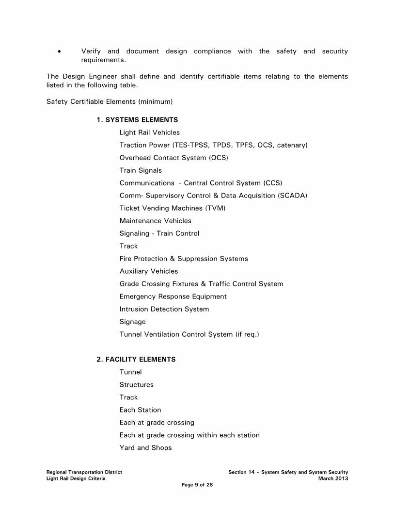
Regional Transportation District Section 14 – System Safety and System Security Light Rail Design Criteria March 2013
Page 9 of 28
• Verify and document design compliance with the safety and security requirements.
The Design Engineer shall define and identify certifiable items relating to the elements listed in the following table.
Safety Certifiable Elements (minimum)
1. SYSTEMS ELEMENTS
Light Rail Vehicles
Traction Power (TES-TPSS, TPDS, TPFS, OCS, catenary)
Overhead Contact System (OCS)
Train Signals
Communications - Central Control System (CCS)
Comm- Supervisory Control & Data Acquisition (SCADA)
Ticket Vending Machines (TVM)
Maintenance Vehicles
Signaling - Train Control
Track
Fire Protection & Suppression Systems
Auxiliary Vehicles
Grade Crossing Fixtures & Traffic Control System
Emergency Response Equipment
Intrusion Detection System
Signage
Tunnel Ventilation Control System (if req.)
2. FACILITY ELEMENTS
Tunnel
Structures
Track
Each Station
Each at grade crossing
Each at grade crossing within each station
Yard and Shops
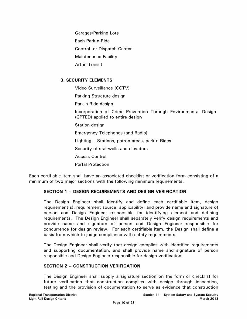
Regional Transportation District Section 14 – System Safety and System Security Light Rail Design Criteria March 2013
Page 10 of 28
Garages/Parking Lots
Each Park-n-Ride
Control or Dispatch Center
Maintenance Facility
Art in Transit
3. SECURITY ELEMENTS
Video Surveillance (CCTV)
Parking Structure design
Park-n-Ride design
Incorporation of Crime Prevention Through Environmental Design (CPTED) applied to entire design
Station design
Emergency Telephones (and Radio)
Lighting – Stations, patron areas, park-n-Rides
Security of stairwells and elevators
Access Control
Portal Protection
Each certifiable item shall have an associated checklist or verification form consisting of a minimum of two major sections with the following minimum requirements.
SECTION 1 -- DESIGN REQUIREMENTS AND DESIGN VERIFICATION
The Design Engineer shall Identify and define each certifiable item, design requirement(s), requirement source, applicability, and provide name and signature of person and Design Engineer responsible for identifying element and defining requirements. The Design Engineer shall separately verify design requirements and provide name and signature of person and Design Engineer responsible for concurrence for design review. For each certifiable item, the Design shall define a basis from which to judge compliance with safety requirements.
The Design Engineer shall verify that design complies with identified requirements and supporting documentation, and shall provide name and signature of person responsible and Design Engineer responsible for design verification.
SECTION 2 -- CONSTRUCTION VERIFICATION
The Design Engineer shall supply a signature section on the form or checklist for future verification that construction complies with design through inspection, testing and the provision of documentation to serve as evidence that construction

Regional Transportation District Section 14 – System Safety and System Security Light Rail Design Criteria March 2013
Page 11 of 28
complies with design.
14.7 RIGHT-OF-WAY FENCING AND BARRIERS
Right-of-Way (ROW) fencing and/or barriers shall be provided along the entire LRT alignment. The fencing and barriers shall be designed to address the following:
• act as a safety barrier to prevent vehicles, trucks, and other highway/roadway users from accidentally entering the LRT envelope;
• shall be of sufficient height to prevent trespass;
• shall be designed to prevent debris and roadway snow removal activity (snow plows throwing slush, ice and other debris) from entering rail envelope and transit station areas; and
• shall incorporate safety considerations on elevated sections with respect to fall protection and providing adequate space for maintenance-of-way workers.
There may be areas where different fencing or barriers may be more appropriate and aesthetic. In these areas, the fencing and/or barrier design shall be determined on a case by case basis and the design shall be accepted by the RTD System Safety Project Manager. The following table describes ROW conditions and the corresponding fencing and barrier requirements. The design shall conform to the requirements contained in the table. For any situation not specifically defined in the table, the fencing and/or barrier design shall be determined on a case by case basis and the design shall be approved by the RTD System Safety Project Manager. These requirements shall be applied regardless of the horizontal or vertical distance from the rail ROW to the adjacent property use. This includes, but is not limited to horizontal and vertical distances between the automobile traffic lane and the rail ROW where state or federal regulations may not require barrier or fence protection. Where different types of fencing/barriers connect, e.g. at-grade to elevated transition points, or at-grade to retaining wall transition points, the design shall accommodate a seamless transition accommodating the integrity of the fence/barrier. For example, a section of ROW may have a three foot jersey barrier with a six foot fence (total height nine feet) that meets up to a three foot MSE wall with a three foot fence (total height six feet). The fencing shall be designed so it tapers from the higher requirement to the lower requirement and meets the performance requirement of this section. Where gaps do occur, due to transitions or where obstacles exist preventing continuous fence, the gap shall be no more than 4 inches between continues fence runs. RTD shall approve the instances where this occurs. For example, if the fencing/barrier terminates at a bridge monument, the fencing shall be attached to the monument.
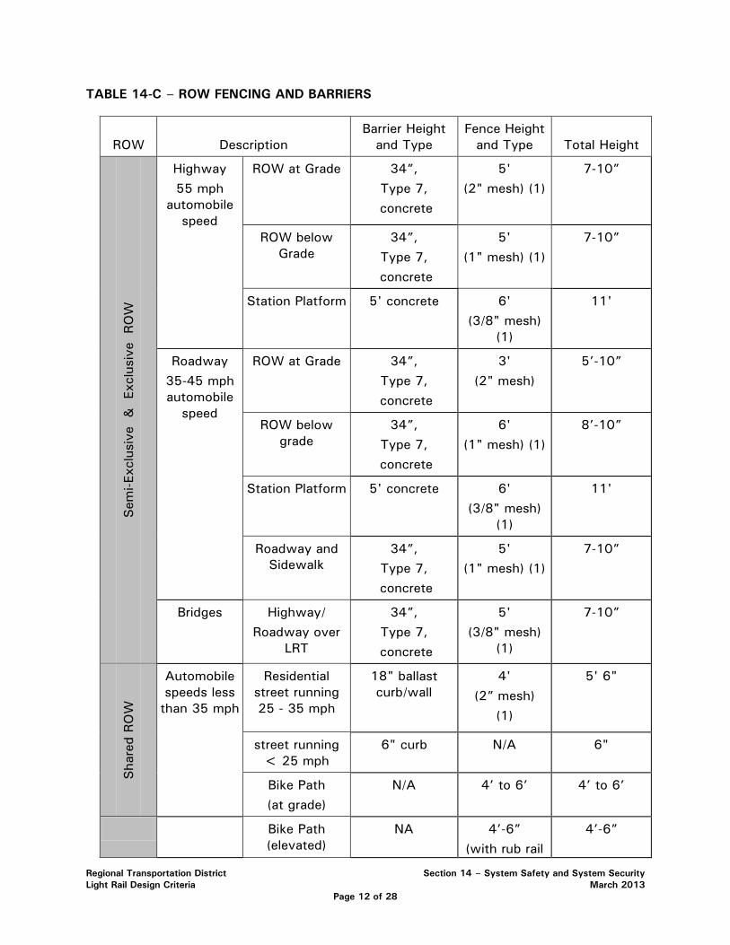
Regional Transportation District Section 14 – System Safety and System Security Light Rail Design Criteria March 2013
Page 12 of 28
TABLE 14-C – ROW FENCING AND BARRIERS
ROW Description Barrier Height
and Type Fence Height
and Type Total Height Sem
i-Exc
lusi
ve &
Ex
clus
ive
RO
W
Highway 55 mph
automobile speed
ROW at Grade 34”, Type 7,
concrete
5' (2" mesh) (1)
7-10”
ROW below Grade
34”, Type 7,
concrete
5' (1" mesh) (1)
7-10”
Station Platform
5' concrete 6' (3/8" mesh)
(1)
11'
Roadway 35-45 mph automobile
speed
ROW at Grade 34”, Type 7,
concrete
3' (2" mesh)
5’-10”
ROW below grade
34”, Type 7,
concrete
6' (1" mesh) (1)
8’-10”
Station Platform
5' concrete 6' (3/8" mesh)
(1)
11'
Roadway and Sidewalk
34”, Type 7,
concrete
5' (1" mesh) (1)
7-10”
Bridges Highway/ Roadway over
LRT
34”, Type 7,
concrete
5' (3/8" mesh)
(1)
7-10”
Sha
red
RO
W
Automobile speeds less
than 35 mph
Residential street running 25 - 35 mph
18" ballast curb/wall
4' (2” mesh)
(1)
5' 6"
street running < 25 mph
6" curb N/A 6"
Bike Path (at grade)
N/A 4’ to 6’
4’ to 6’
Bike Path (elevated)
NA 4’-6” (with rub rail
4’-6”

Regional Transportation District Section 14 – System Safety and System Security Light Rail Design Criteria March 2013
Page 13 of 28
Note: Exact fence height, type and mesh size shall be determined by site-specific hazard analysis taking into account all factors including protection of the overhead catenary system. Final design shall be approved by the RTD System Safety Project Manager.
14.8 EMERGENCY ACCESS/EGRESS, STATION DESIGN, AND WALKWAYS
The design shall include emergency access and egress points along the alignment per NFPA 130 requirements. The design shall identify emergency access and egress locations and shall provide a list or matrix of the necessary elements to be provided at each exit, such as lighting, signage, lock hardware, intrusion detection, and other elements as required by NFPA 130 and local jurisdictions. The design shall incorporate a preliminary emergency evacuation plan and diagrams for the corridor, including each station, identifying primary and secondary evacuation routes and points of safety.
LRT station design shall meet the “Means of Egress” requirements for stations as identified in NFPA 130. The Design Engineer shall provide a draft and final Means of Egress Report for all stations documenting that station design meets or exceeds all criteria listed in NFPA 130. The report shall include all calculations, supporting documentation, engineering drawings and other information necessary to demonstrate compliance with NFPA 130. For calculation of occupant load, the Design Engineer shall use projected ridership figures or maximum trainload capacities if accurate projections are not available. Each station shall have a minimum of two main access/egress points remotely located from one another. There shall be sufficient exit lanes to evacuate the station occupant load, as defined in NFPA 130, from the station platform in 4 minutes or less. The maximum travel distance to an exit from any point on the platform shall not exceed 300 feet. Stations shall also be designed to permit evacuation from the most remote point on the platform to a point of safety in 6 minutes or less.
The design shall incorporate walkways as follows. An emergency/maintenance walkway shall be provided along structures. The walkway shall be above TOR at the track edge and shall be located at a horizontal distance from track centerline as determined by regulations plus appropriate Other Wayside Factors, and Running Clearance. The walkway shall have a minimum width of 30 inches. A walkway shall be provided adjacent to one side of every track. Walkways in underground LRT structures, bridges and flyovers regardless of length, shall consist of a solid type material that provides a smooth continuous walking surface (concrete, etc.). Walkways shall have a slip-resistant design and shall be constructed of noncombustible materials.
Along the trackway, walkways shall be provided in addition to the clearance envelope requirements per Section 4.2, it is required that space be provided for emergency/maintenance walkways adjacent to the trackway. The walkway envelope shall extend at least 2 feet-6 inches from the edge of the clearance envelope and shall extend to 6 feet-6 inches above the walkway. A walkway shall be provided adjacent to one side
@ 42”)

Regional Transportation District Section 14 – System Safety and System Security Light Rail Design Criteria March 2013
Page 14 of 28
of every track. In certain instances, with prior approval from the RTD System Safety Project Manager, the walkway may be between two tracks to serve both. In either case the walkway shall permit unobstructed passage from which passengers can be evacuated. Crosswalks shall have a uniform walking surface at top of rail. Walkway continuity shall be maintained at special track sections (e.g., crossovers, pocket tracks, other special track sections). For walkway clearance calculations only, traction power poles shall not be considered a permanent obstruction. This requirement is not applicable to paved track sections in street ROW. Walkways shall be placed to allow passengers to evacuate a train at any point along the trainway so that they can proceed to the nearest station or other point of safety per NFPA 130 requirements.
14.9 GRADE CROSSINGS
The LRT design shall incorporate approaches that minimize hazards and risks to LRT, pedestrians, bicyclists and motor vehicle operators. The primary method to minimize grade crossing hazards is to eliminate at grade crossings or minimize the number of at grade LRT crossings. Pedestrian only and bicycle only at grade crossings are generally prohibited and will require a case by case evaluation and written RTD approval. The exceptions to this criteria are pedestrian and bicycle crossings at stations with paved track.
Where planning and design does not allow for the elimination of an at grade crossing, the following system safety precedence shall be applied: design for minimum risk, incorporate safety devices, and provide warning devices. A combination of active grade crossing warning devices and passive warning devices is preferred to solely using passive warning devices. Active warning devices include: gates, bells, flashing lights, and grade crossing indicators for train operators. Passive warning devices include signage and pavement markings.
Design of each at grade crossing shall be subject to the circumstances of that crossing and its relation to the transit corridor. In considering appropriate control and warning devices, consideration shall be given to the following: type of alignment (exclusive, semi-exclusive, or shared ROW); configuration and geometry of crossing (angled or mid-block crossing; operating speed of all users; line of sight of all users; pedestrian activity; school zone; and extreme surges (pedestrians and vehicles).
To enhance pedestrian and bicycle safety at crossings, consideration shall be given to the use of channeling. The purpose of channeling is to create a physical barrier that prevents or discourages persons from taking shortcuts or from crossing the track way in a risky or unauthorized manner. Effective channeling may be developed through the use of fencing, landscaping, bollard and chain, railing, sidewalks or other methods. In all cases, a channeling method that enhances sight lines to an approaching train shall be selected.
Additional elements that may improve pedestrian and bicycle safety at crossings include: swing gates, pedestrian barriers, and automatic pedestrian gates. The purpose of a swing gate is to slow persons who are hurriedly approaching the track way. Swing gate operation depends upon the judgment of the individual. It is not electrically interconnected into approaching train or vehicular traffic signal systems. Swing gates may be appropriate

Regional Transportation District Section 14 – System Safety and System Security Light Rail Design Criteria March 2013
Page 15 of 28
where:
• There is a high likelihood that persons will hurriedly cross the track way, or sight lines and distance are restricted, and
• Channeling or other barriers reasonably prevent persons from bypassing the swing gates, and
• Acceptable provisions for opening the gates by disabled persons can be provided.
Swing gates shall open away from the tracks. Pedestrians shall pull the gate to open it and enter the track way. Gates shall also permit quick exit from the track way, automatically close after use, and be light and easy to operate by all persons.
Pedestrian barriers are also intended to slow persons who are hurriedly approaching the track way. Major advantages of barriers are that there are no operating parts to maintain, and that disabled persons are less impeded. Pedestrian barriers may be appropriate where:
• There is a high likelihood that persons will hurriedly cross the track way, or sight lines and distance are restricted, and
• Channeling or other barriers reasonably prevent persons from bypassing the barriers, and
• Adequate space is available to accommodate installation.
Barrier positioning shall accommodate use by disabled persons and be positioned so persons are turned to face the nearest on-coming train prior to crossing the track way.
Automatic pedestrian gates prevent or discourage a pedestrian or bicyclist from crossing the track way when a train is approaching. Automatic pedestrian gates are electrically interconnected into and activated by the train signal system. Automatic pedestrian gates may be considered in situations where the use of swing gates and barriers may not be effective due to train speeds and severely limited sight distance.
All gated grade crossings shall have video surveillance per the requirements of Section 14.10.0 Video Surveillance. Each gated grade crossing shall have two IP HD cameras, which are connected to the RTD communications network and recorded.
The Design Engineer shall prepare diagrams for swing gates and pedestrian bedstead barriers.
14.10 VIDEO SURVEILLANCE
The design shall incorporate video surveillance into the project. The video surveillance system shall be capable of dual streaming live video feeds. Technicians at the Command Center will receive pictures at a full 30 frames per second. A second stream will store video images at 15 frames per second. The video surveillance system shall be capable of transmitting video to RTD’s Security Command Center via a fiber optic transmission

Regional Transportation District Section 14 – System Safety and System Security Light Rail Design Criteria March 2013
Page 16 of 28
backbone or other suitable transmission network, such as Cat 5e or higher cable for IP transmission. Understanding that technology changes rapidly, most current industry standards will be utilized in design and construction. RTD, through the Security Systems Manager/Administrator, must approve any proposed deviations in technology from the listed standards for the video surveillance system.
All video cameras will be recorded on a Network Video Recorder (NVR). Redundancy shall be designed into the system, an N+1 solution. Minimum recording time will be 30 days. The Video Management Software (VMS) shall be compatible with the existing RTD VMS system.
The design shall include all system elements including communication houses, transmission infrastructure, IP HD digital color cameras, IP switches, and network video recorders. The design shall incorporate video surveillance covering station platforms, emergency telephones, elevator cabs, elevator waiting areas, stairwell entries, parking structures, pedestrian tunnels and pedestrian bridges. The minimum number of cameras to provide coverage of these transit elements is as follows.
TABLE 14D – MINIMUM CAMERA COVERAGE
Single level at grade station platform of 300 feet or less *
Platform type Fixed color camera Pan-Tilt-Zoom color camera
Center platform 4 2
Side/Center platform 6 2
Side/Side platform 4 4
Triple platform (side with two centers)
10 3
*For stations with vertical circulation, the minimum number of cameras is as stated above plus: one fixed color camera per elevator waiting area per floor, one fixed color camera per stairwell entry per floor, and one fixed color camera per each emergency telephone. Elevators shall have a minimum of one fixed color camera inside each elevator cab.
*For stations greater than 300 feet in length additional cameras will be required. The exact number will be dependent on the station design.
TABLE 14E – PARKING STRUCTURE CAMERAS
Vehicle spaces
Vehicle entrance/ exit **
Elevator waiting area*
Stairwell entrance
area*
Emergency telephone*

Regional Transportation District Section 14 – System Safety and System Security Light Rail Design Criteria March 2013
Page 17 of 28
1 camera per 35 vehicle spaces
1 camera per vehicle entrance/ exit lane
1 camera per waiting
area per floor
1 camera per entrance area per
floor
1 camera per emergency telephone
*Subject to approval by the RTD Security Systems Manager/Administrator, if the design accommodates a cluster of the elevator waiting area, stairwell entrance, and emergency telephone, a single camera may be used if the video coverage of all three elements is satisfactory. Elevators shall have a minimum of one fixed color camera inside each elevator cab.
**5 Megapixel (MP), or greater, cameras shall be utilized at all vehicle entrance/exit locations in addition to an IR (infra-red) illuminator, on a photo cell, to capture vehicles and license plate numbers of vehicles entering and exiting the structure.
***All parking structure cameras other than the entry/exit cameras shall be color, pan-tilt-zoom.
TABLE 14F – PEDESTRIAN TUNNEL CAMERAS
Pedestrian Tunnel* (all cameras are color, pan-tilt-zoom, 4 cameras minimum per tunnel)
1 camera focused on each portal entrance/exit (2 cameras)
1 camera inside each tunnel portal entrance/exit focused inside the tunnel (2 cameras)
*For tunnels in excess of 150 feet, additional cameras will be required. If a tunnel has a bend or turn, additional cameras will be required. The RTD Security Systems Manager/Administrator will determine the number of additional cameras necessary for coverage.
*Cameras at the entrances into tunnels will be IP HD cameras with wide dynamic range built into the feature set to compensate for varying light levels.
TABLE 14G – PEDESTRIAN BRIDGE CAMERAS
Pedestrian Bridge (all cameras are color, pan-tilt-zoom, 2 cameras minimum per bridge)
1 camera inside each bridge portal entrance/exit focused inside the bridge
*For bridges in excess of 150 feet, additional cameras will be required. If a bridge has a bend or turn, additional cameras may be required. The RTD Security Systems Manager/Administrator will determine the number of additional cameras necessary for coverage.
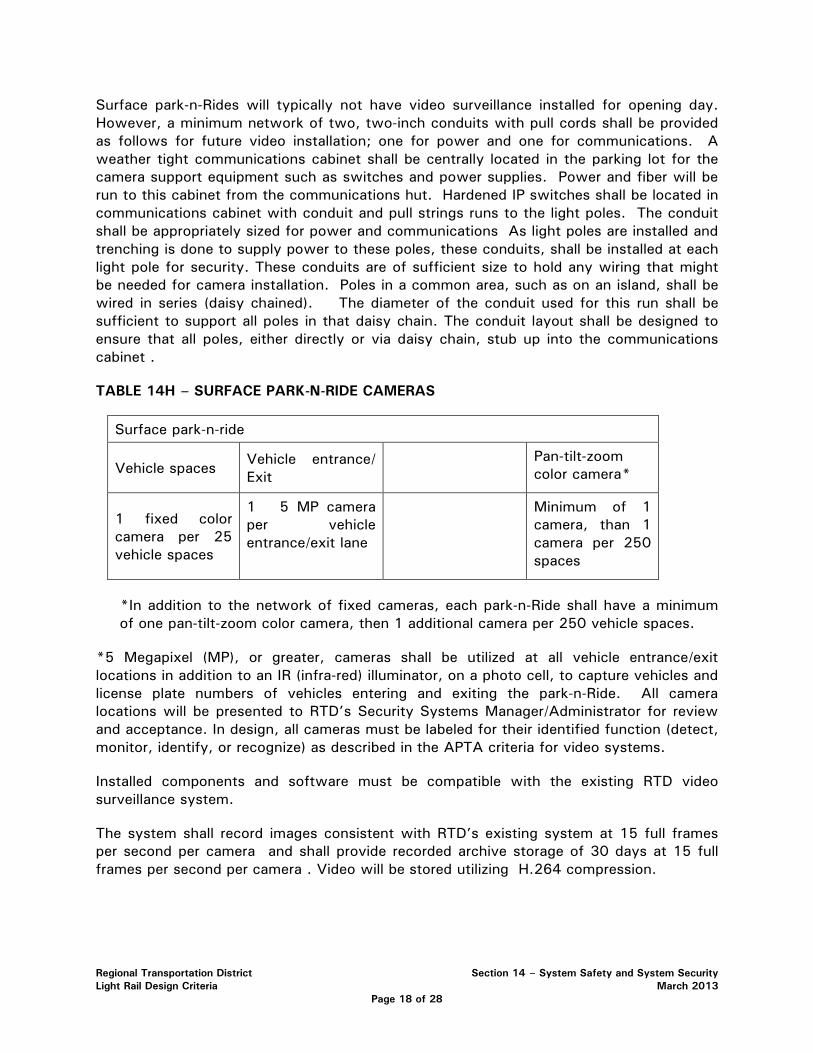
Regional Transportation District Section 14 – System Safety and System Security Light Rail Design Criteria March 2013
Page 18 of 28
Surface park-n-Rides will typically not have video surveillance installed for opening day. However, a minimum network of two, two-inch conduits with pull cords shall be provided as follows for future video installation; one for power and one for communications. A weather tight communications cabinet shall be centrally located in the parking lot for the camera support equipment such as switches and power supplies. Power and fiber will be run to this cabinet from the communications hut. Hardened IP switches shall be located in communications cabinet with conduit and pull strings runs to the light poles. The conduit shall be appropriately sized for power and communications As light poles are installed and trenching is done to supply power to these poles, these conduits, shall be installed at each light pole for security. These conduits are of sufficient size to hold any wiring that might be needed for camera installation. Poles in a common area, such as on an island, shall be wired in series (daisy chained). The diameter of the conduit used for this run shall be sufficient to support all poles in that daisy chain. The conduit layout shall be designed to ensure that all poles, either directly or via daisy chain, stub up into the communications cabinet .
TABLE 14H – SURFACE PARK-N-RIDE CAMERAS
Surface park-n-ride
Vehicle spaces Vehicle entrance/ Exit
Pan-tilt-zoom color camera*
1 fixed color camera per 25 vehicle spaces
1 5 MP camera per vehicle entrance/exit lane
Minimum of 1 camera, than 1 camera per 250 spaces
*In addition to the network of fixed cameras, each park-n-Ride shall have a minimum of one pan-tilt-zoom color camera, then 1 additional camera per 250 vehicle spaces.
*5 Megapixel (MP), or greater, cameras shall be utilized at all vehicle entrance/exit locations in addition to an IR (infra-red) illuminator, on a photo cell, to capture vehicles and license plate numbers of vehicles entering and exiting the park-n-Ride. All camera locations will be presented to RTD’s Security Systems Manager/Administrator for review and acceptance. In design, all cameras must be labeled for their identified function (detect, monitor, identify, or recognize) as described in the APTA criteria for video systems.
Installed components and software must be compatible with the existing RTD video surveillance system.
The system shall record images consistent with RTD’s existing system at 15 full frames per second per camera and shall provide recorded archive storage of 30 days at 15 full frames per second per camera . Video will be stored utilizing H.264 compression.
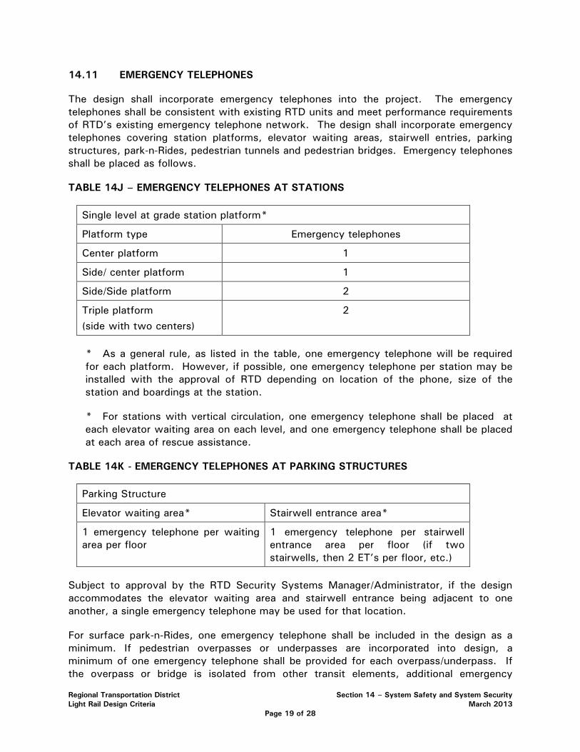
Regional Transportation District Section 14 – System Safety and System Security Light Rail Design Criteria March 2013
Page 19 of 28
14.11 EMERGENCY TELEPHONES
The design shall incorporate emergency telephones into the project. The emergency telephones shall be consistent with existing RTD units and meet performance requirements of RTD’s existing emergency telephone network. The design shall incorporate emergency telephones covering station platforms, elevator waiting areas, stairwell entries, parking structures, park-n-Rides, pedestrian tunnels and pedestrian bridges. Emergency telephones shall be placed as follows.
TABLE 14J – EMERGENCY TELEPHONES AT STATIONS
Single level at grade station platform*
Platform type Emergency telephones
Center platform 1
Side/ center platform 1
Side/Side platform 2
Triple platform (side with two centers)
2
* As a general rule, as listed in the table, one emergency telephone will be required for each platform. However, if possible, one emergency telephone per station may be installed with the approval of RTD depending on location of the phone, size of the station and boardings at the station.
* For stations with vertical circulation, one emergency telephone shall be placed at each elevator waiting area on each level, and one emergency telephone shall be placed at each area of rescue assistance.
TABLE 14K - EMERGENCY TELEPHONES AT PARKING STRUCTURES
Parking Structure
Elevator waiting area* Stairwell entrance area*
1 emergency telephone per waiting area per floor
1 emergency telephone per stairwell entrance area per floor (if two stairwells, then 2 ET’s per floor, etc.)
Subject to approval by the RTD Security Systems Manager/Administrator, if the design accommodates the elevator waiting area and stairwell entrance being adjacent to one another, a single emergency telephone may be used for that location.
For surface park-n-Rides, one emergency telephone shall be included in the design as a minimum. If pedestrian overpasses or underpasses are incorporated into design, a minimum of one emergency telephone shall be provided for each overpass/underpass. If the overpass or bridge is isolated from other transit elements, additional emergency
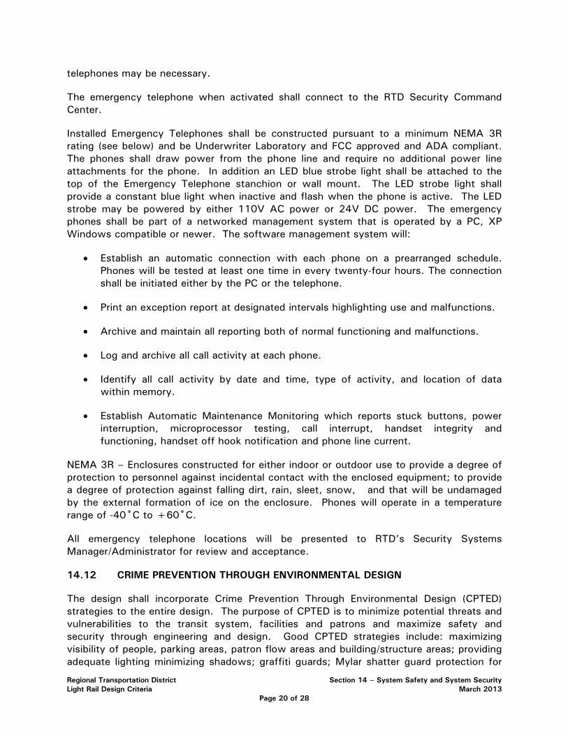
Regional Transportation District Section 14 – System Safety and System Security Light Rail Design Criteria March 2013
Page 20 of 28
telephones may be necessary.
The emergency telephone when activated shall connect to the RTD Security Command Center.
Installed Emergency Telephones shall be constructed pursuant to a minimum NEMA 3R rating (see below) and be Underwriter Laboratory and FCC approved and ADA compliant. The phones shall draw power from the phone line and require no additional power line attachments for the phone. In addition an LED blue strobe light shall be attached to the top of the Emergency Telephone stanchion or wall mount. The LED strobe light shall provide a constant blue light when inactive and flash when the phone is active. The LED strobe may be powered by either 110V AC power or 24V DC power. The emergency phones shall be part of a networked management system that is operated by a PC, XP Windows compatible or newer. The software management system will:
• Establish an automatic connection with each phone on a prearranged schedule. Phones will be tested at least one time in every twenty-four hours. The connection shall be initiated either by the PC or the telephone.
• Print an exception report at designated intervals highlighting use and malfunctions.
• Archive and maintain all reporting both of normal functioning and malfunctions.
• Log and archive all call activity at each phone.
• Identify all call activity by date and time, type of activity, and location of data within memory.
• Establish Automatic Maintenance Monitoring which reports stuck buttons, power interruption, microprocessor testing, call interrupt, handset integrity and functioning, handset off hook notification and phone line current.
NEMA 3R – Enclosures constructed for either indoor or outdoor use to provide a degree of protection to personnel against incidental contact with the enclosed equipment; to provide a degree of protection against falling dirt, rain, sleet, snow, and that will be undamaged by the external formation of ice on the enclosure. Phones will operate in a temperature range of -40˚C to +60˚C.
All emergency telephone locations will be presented to RTD’s Security Systems Manager/Administrator for review and acceptance.
14.12 CRIME PREVENTION THROUGH ENVIRONMENTAL DESIGN
The design shall incorporate Crime Prevention Through Environmental Design (CPTED) strategies to the entire design. The purpose of CPTED is to minimize potential threats and vulnerabilities to the transit system, facilities and patrons and maximize safety and security through engineering and design. Good CPTED strategies include: maximizing visibility of people, parking areas, patron flow areas and building/structure areas; providing adequate lighting minimizing shadows; graffiti guards; Mylar shatter guard protection for

Regional Transportation District Section 14 – System Safety and System Security Light Rail Design Criteria March 2013
Page 21 of 28
glass windows; landscape plantings that maximize visibility; gateway treatments; decorative fencing; perimeter control; fencing; minimizing park-n-ride and parking structure access points; elimination of structural hiding places; open lines of sight; visible stairwells and elevators meaning the exterior walls are constructed of transparent material; and painting with light.
Examples of CPTED strategy include:
• Adequate lighting of all areas appropriate for their use including perimeter lighting in park-n-Rides so the edge of the park-n-Ride is illuminated the same as the rest of the park-n-Ride (refer to station design criteria for lighting levels).
• When using shrubs, use species with a maximum height or spread that will minimize visibility obstructions. The preliminary design shall be approved by RTD prior to final design and implementation.
• When using trees, use deciduous trees with branches no lower than six feet from ground surface.
The design shall incorporate CPTED strategies into the Threat and Vulnerability Analysis and Resolution process described in the following section, 14.13.0 Threat and Vulnerability Analysis and Resolution.
14.13 THREAT AND VULNERABILITY ANALYSIS AND RESOLUTION
The design shall incorporate a Threat and Vulnerability Analysis and Resolution process in accordance with the minimum criteria outlined in this section. A risk assessment is a comprehensive study of a system to identify those components most vulnerable to disruption or destruction and to assess the likely impact that such disruption or destruction would have on passengers, employees, and the RTD system. Threat and vulnerability analysis (TVA) work shall begin upon project initiation and continue throughout the project. The design shall incorporate TVA progress reports according to a mutually agreeable schedule. The design shall include a draft and final TVA report on the preliminary engineering. The TVA document itself is a living document, which must be revised and updated as the system design and development progresses. It becomes the input document and information for all other TVA performed on the system.
The process shall assign values to design elements based on their criticality to the transit system operations. The four level risk classification system listed below will be used to assess risk levels.
14.13.1 SEVERITY CATEGORIES
See Section 14.3.1, Hazard Severity Definitions.
14.13.2 TRANSIT RISK ASSESSMENT LEVELS
TABLE 14K - TRANSIT RISK ASSESSMENT LEVELS
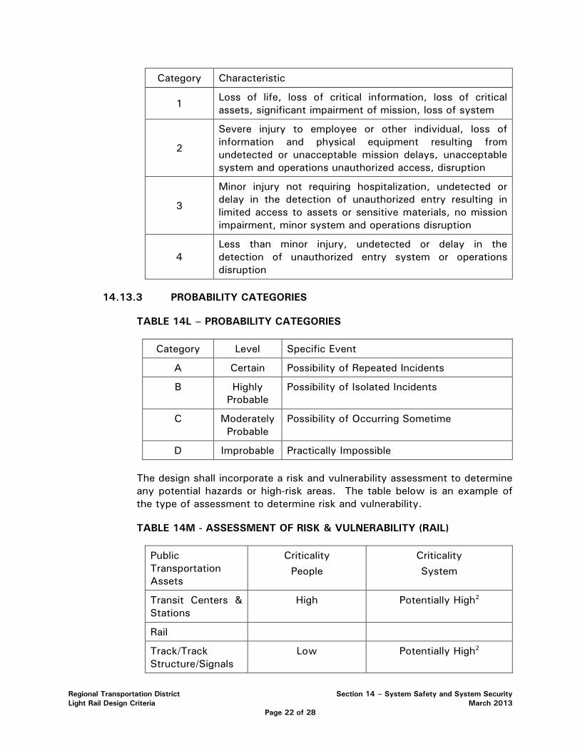
Regional Transportation District Section 14 – System Safety and System Security Light Rail Design Criteria March 2013
Page 22 of 28
Category Characteristic
1 Loss of life, loss of critical information, loss of critical assets, significant impairment of mission, loss of system
2
Severe injury to employee or other individual, loss of information and physical equipment resulting from undetected or unacceptable mission delays, unacceptable system and operations unauthorized access, disruption
3
Minor injury not requiring hospitalization, undetected or delay in the detection of unauthorized entry resulting in limited access to assets or sensitive materials, no mission impairment, minor system and operations disruption
4 Less than minor injury, undetected or delay in the detection of unauthorized entry system or operations disruption
14.13.3 PROBABILITY CATEGORIES
TABLE 14L – PROBABILITY CATEGORIES
Category Level Specific Event
A Certain Possibility of Repeated Incidents
B Highly Probable
Possibility of Isolated Incidents
C Moderately Probable
Possibility of Occurring Sometime
D Improbable Practically Impossible
The design shall incorporate a risk and vulnerability assessment to determine any potential hazards or high-risk areas. The table below is an example of the type of assessment to determine risk and vulnerability.
TABLE 14M - ASSESSMENT OF RISK & VULNERABILITY (RAIL)
Public Transportation Assets
Criticality People
Criticality System
Transit Centers & Stations
High Potentially High2
Rail
Track/Track Structure/Signals
Low Potentially High2

Regional Transportation District Section 14 – System Safety and System Security Light Rail Design Criteria March 2013
Page 23 of 28
Cars High 1
Maintenance Yards
Low Medium
Switching Stations Low Medium
Electric Power
Source for System Medium High
Substations Low Medium
Command Control Center
Low3 High
Revenue Collection Center
Low3 Medium
Bridges Medium Medium2
Tunnels Medium Medium2
Fans Low Medium
Vents Low Medium
Emergency Hatches
Low Medium
TABLE 14N - ASSESSMENT OF RISK & VULNERABILITY (BUS)
Public Transportation Assets
Criticality People
Criticality System
Bus Terminals High 1 Potentially High2
Bus Vehicles High 1 Low
Bus Stops/Shelters Medium Low
Maintenance Garages
Low3 Medium
Fuel Storage Facility
Low High
Command Control Center
Low3 High
Revenue Collection Center
Low3 Medium
1Depends on what time of day incident occurs. Greater impact would be experienced during rush hour than non-rush hours
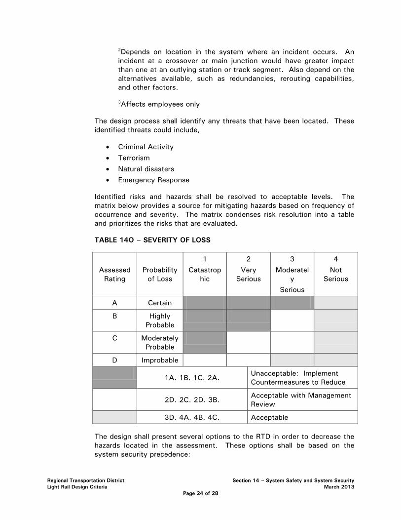
Regional Transportation District Section 14 – System Safety and System Security Light Rail Design Criteria March 2013
Page 24 of 28
2Depends on location in the system where an incident occurs. An incident at a crossover or main junction would have greater impact than one at an outlying station or track segment. Also depend on the alternatives available, such as redundancies, rerouting capabilities, and other factors.
3Affects employees only
The design process shall identify any threats that have been located. These identified threats could include,
• Criminal Activity
• Terrorism
• Natural disasters
• Emergency Response
Identified risks and hazards shall be resolved to acceptable levels. The matrix below provides a source for mitigating hazards based on frequency of occurrence and severity. The matrix condenses risk resolution into a table and prioritizes the risks that are evaluated.
TABLE 14O – SEVERITY OF LOSS
Assessed Rating
Probability of Loss
1 Catastrop
hic
2 Very
Serious
3 Moderatel
y Serious
4 Not
Serious
A Certain
B Highly Probable
C Moderately Probable
D Improbable
1A. 1B. 1C. 2A.
Unacceptable: Implement Countermeasures to Reduce
2D. 2C. 2D. 3B.
Acceptable with Management Review
3D. 4A. 4B. 4C. Acceptable
The design shall present several options to the RTD in order to decrease the hazards located in the assessment. These options shall be based on the system security precedence:
Regional Transportation District Section 14 – System Safety and System Security Light Rail Design Criteria March 2013
Page 25 of 28
• Design the system to eliminate the risk
• Design the system to control the risk
• Add safety or security devices to control the risk
• Add warning devices to control the risk, and
• Institute special procedures or training to control the risk.
14.14 PARK-N-RIDES, PARKING STRUCTURES, AND ENCLOSED UNDERGROUND OR BELOW GRADE TRANSIT FACILITIES
14.14.1 SURFACE PARK-N-RIDES
In addition to the items already listed in this chapter, design for surface park-n-Rides shall consider safety and security of patrons and the protection of property. Park-n-Ride design shall incorporate good visibility throughout the park-n-Ride, and good visibility from surrounding streets into the park-n-Ride for patrols by law enforcement and security personnel.
The use of landscaping shall consider maximizing visibility and eliminating hiding places and shadows. Shrubs shall not impede visibility in height and trees shall bear no branches below 6 feet from ground surface. Evergreen trees shall only be used on a limited basis and shall be placed in such a manner that hiding spaces and visual obstructions are not created. Landscape placement shall be subject to approval by the RTD Security Systems Administrator.
Adequate and appropriate lighting is the single most effective deterrent for minimizing crime at park-n-Rides. Lighting shall be provided in accordance with the criteria provided in the stations chapter. The design shall address perimeter lighting by including placement of light poles around the perimeter of the park-n-Ride.
The control and design of park-n-Ride entrances and exits is important to maintaining security of park-n-Rides. Entrances and exits shall be limited to as few as practically possible to control access and egress from the park-n-Ride site and minimize the number of entrance and exit cameras. To complement the effective use of video surveillance, traffic calming features (i.e. speed bumps) shall be considered at entrances and exits on a case-by-case basis to slow the vehicles as they enter and exit to allow adequate time for automobile license plates to be captured by video surveillance. Where speed bumps are used for these purposes, they shall include two speed bumps separated by one and one half standard vehicle lengths.
Regional Transportation District Section 14 – System Safety and System Security Light Rail Design Criteria March 2013
Page 26 of 28
14.14.2 PARKING STRUCTURES
In addition to the items already listed in this chapter, design for parking structures shall consider safety and security of patrons and the protection of property. Parking structure design shall incorporate good visibility throughout the structure, and good visibility from surrounding streets into the structure for patrols by law enforcement and security personnel. Walls inside the structure shall be limited to increase visibility and minimize hiding places throughout the structure. Openings in interior walls between levels or ramps shall be protected by mesh or chain link fencing. Openings in exterior walls at the ground level and at below grade level shall be protected by mesh, chain link fence or other treatment to prevent pedestrians from entering or exiting the structure through these openings.
The control and design of parking structure entrances and exits is important to maintaining security of the structures. Entrances and exits shall be limited to as few as practically possible to control access and egress from the structure and minimize the number of entrance and exit cameras.
Stairwell and elevator design shall maximize the interior visibility of the stairwell, elevator and elevator shaft. Materials of wall construction for these elements shall be transparent such as glass and allow visibility from at least three sides.
Each parking structure shall include a security room/office for security or law enforcement personnel.
Parking structures shall have minimum lighting levels of 5 foot candles.
14.14.3 UNDERGROUND AND BELOW GRADE TRANSIT FACILITIES
Enclosed, underground, and below-grade transit facilities present unique security design challenges. Design of these facilities shall maximize patron safety and security by the inclusion of counterterrorism measures. Each enclosed, underground or below grade facility shall be covered by video surveillance including: its perimeter; portals, entrances and exits; its interior; and fare vending areas. Patron station areas in these facilities shall be designed as paid fare zones. Thus, patron circulation design shall consider the availability to purchase fare media prior to entering the paid fare zones.
Where facilities serve more than one mode of transportation, the design shall incorporate a means to physically separate modal areas using automatic doors. Each modal area shall also have a separate ventilation system. This design shall allow one modal area to operate in the event of a major incident occurring in an adjacent modal area and prevent cross contamination.
Facility access control is an important aspect of design and shall be designed as follows. All access points (entrances and exits) to the facility and all
Regional Transportation District Section 14 – System Safety and System Security Light Rail Design Criteria March 2013
Page 27 of 28
interior doors shall be controlled by proximity reader access control. The proximity reader access control system shall be a Lenel system as currently installed at RTD facilities and shall be networked into the existing system. All access points or portals capable of accommodating a motor vehicle shall be equipped with automatic portal protection that will prevent unauthorized vehicles from entering the facility. The portal protection shall have a K-12 rating, shall include a guard shack, and shall be located at a minimum distance of 150 feet from the facility entry portal. Portals for train access shall include intrusion detection capable of distinguishing between an authorized train and any other unauthorized vehicle or person attempting to gain access through the train portal. Intrusion detection alarm notification shall be sent to light rail central control and RTD Security Command Center. The facility design shall incorporate a means to establish a vehicle checkpoint at a minimum distance of 150 feet from each facility vehicle entry portal.
The design shall protect the facility from progressive collapse. In the event of an internal explosion, the design shall prevent progressive collapse due to the loss of one primary column. Column design shall consider sizing, reinforcement or protection so that the threat charge will not cause the column to be critically damaged.
Loading docks and shipping/receiving areas are prohibited in underground and below grade facilities. All deliveries shall be accommodated for at the exterior of the facility above grade.
Each enclosed, underground or below grade facility shall include a security room/office for security or law enforcement personnel.
14.15.0 PUBLICLY ACCESSIBLE RECEPTACLES
Publicly accessible receptacles are any receptacle with a void space that the public can access. Examples include but are not limited to trash receptacles, bike lockers, and news racks. Placement of publicly accessible receptacles shall be subject to threat and vulnerability analysis and shall not be placed within 250 feet of a station, station area or patron gathering area for outside locations. An exception is the use of an explosion resistant trash receptacle or other receptacle meeting the requirements of the Department of Homeland Security. For enclosed areas, underground, or below grade transit stations, facilities, structures and tunnels, placement of publicly accessible receptacles is strictly prohibited. In parking structures, placement of publicly accessible receptacles is strictly prohibited.

Regional Transportation District Section 14 – System Safety and System Security Light Rail Design Criteria March 2013
Page 28 of 28
14.16.0 CONFIGURATION MANAGEMENT
Any change or deviation to this design criteria must be approved by RTD’s Executive Safety and Security Committee. All project design shall be reviewed and accepted RTD’s Executive Safety and Security Committee.

RTD Design Guidelines & Criteria Section 15 – At-Grade Crossings Light Rail Design Criteria December 9, 2014
Page 1 of 22
TABLE OF CONTENTS SECTION 15 – AT-GRADE CROSSINGS
ALIGNMENTS ...............................................................................................................................3 15.1
Exclusive ............................................................................................................... 3 15.1.1
Semi-exclusive ...................................................................................................... 4 15.1.2
Mixed-use ............................................................................................................. 5 15.1.3
CROSSING TREATMENT OVERVIEW ........................................................................................5 15.2 ENGINEERING STUDY ................................................................................................................6 15.3 HAZARD ANALYSIS ....................................................................................................................8 15.4 CROSSING TREATMENTS ..........................................................................................................9 15.5
Recommended Typical Signage: ......................................................................... 10 15.5.1
Tactile Warning Surface ...................................................................................... 11 15.5.2
Reduced Noise Crossings ................................................................................... 12 15.5.3
Highway At-grade Crossing Warning Signals ...................................................... 12 15.5.4
SEMI-EXCLUSIVE ALIGNMENTS ............................................................................................ 13 15.6 MIXED-USE ALIGNMENTS ....................................................................................................... 14 15.7
APPENDICES
RTD Design Guidelines & Criteria Section 15 – At-Grade Crossings Light Rail Design Criteria December 9, 2014
Page 2 of 22
THIS PAGE LEFT INTENTIONALLY BLANK
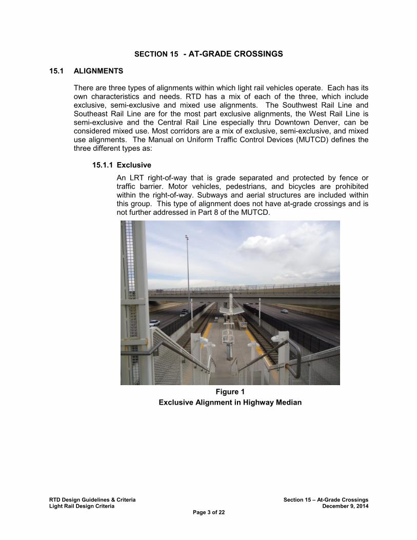
RTD Design Guidelines & Criteria Section 15 – At-Grade Crossings Light Rail Design Criteria December 9, 2014
Page 3 of 22
SECTION 15 - AT-GRADE CROSSINGS
ALIGNMENTS 15.1
There are three types of alignments within which light rail vehicles operate. Each has its own characteristics and needs. RTD has a mix of each of the three, which include exclusive, semi-exclusive and mixed use alignments. The Southwest Rail Line and Southeast Rail Line are for the most part exclusive alignments, the West Rail Line is semi-exclusive and the Central Rail Line especially thru Downtown Denver, can be considered mixed use. Most corridors are a mix of exclusive, semi-exclusive, and mixed use alignments. The Manual on Uniform Traffic Control Devices (MUTCD) defines the three different types as:
Exclusive 15.1.1
An LRT right-of-way that is grade separated and protected by fence or traffic barrier. Motor vehicles, pedestrians, and bicycles are prohibited within the right-of-way. Subways and aerial structures are included within this group. This type of alignment does not have at-grade crossings and is not further addressed in Part 8 of the MUTCD.
Figure 1
Exclusive Alignment in Highway Median
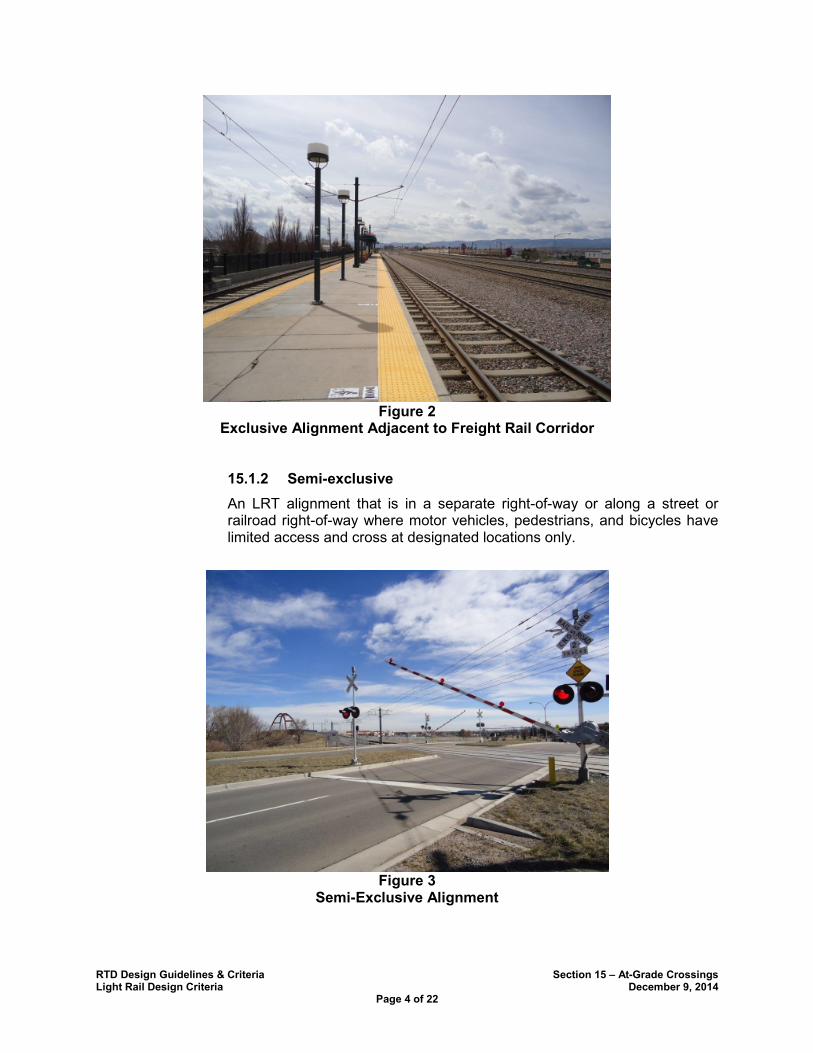
RTD Design Guidelines & Criteria Section 15 – At-Grade Crossings Light Rail Design Criteria December 9, 2014
Page 4 of 22
Figure 2
Exclusive Alignment Adjacent to Freight Rail Corridor
Semi-exclusive 15.1.2
An LRT alignment that is in a separate right-of-way or along a street or railroad right-of-way where motor vehicles, pedestrians, and bicycles have limited access and cross at designated locations only.
Figure 3
Semi-Exclusive Alignment
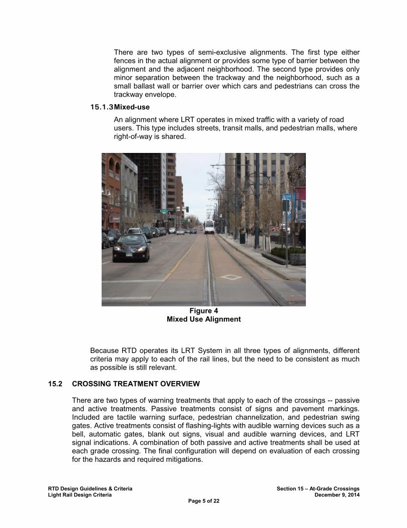
RTD Design Guidelines & Criteria Section 15 – At-Grade Crossings Light Rail Design Criteria December 9, 2014
Page 5 of 22
There are two types of semi-exclusive alignments. The first type either fences in the actual alignment or provides some type of barrier between the alignment and the adjacent neighborhood. The second type provides only minor separation between the trackway and the neighborhood, such as a small ballast wall or barrier over which cars and pedestrians can cross the trackway envelope.
Mixed-use 15.1.3
An alignment where LRT operates in mixed traffic with a variety of road users. This type includes streets, transit malls, and pedestrian malls, where right-of-way is shared.
Figure 4
Mixed Use Alignment
Because RTD operates its LRT System in all three types of alignments, different criteria may apply to each of the rail lines, but the need to be consistent as much as possible is still relevant.
CROSSING TREATMENT OVERVIEW 15.2
There are two types of warning treatments that apply to each of the crossings -- passive and active treatments. Passive treatments consist of signs and pavement markings. Included are tactile warning surface, pedestrian channelization, and pedestrian swing gates. Active treatments consist of flashing-lights with audible warning devices such as a bell, automatic gates, blank out signs, visual and audible warning devices, and LRT signal indications. A combination of both passive and active treatments shall be used at each grade crossing. The final configuration will depend on evaluation of each crossing for the hazards and required mitigations.

RTD Design Guidelines & Criteria Section 15 – At-Grade Crossings Light Rail Design Criteria December 9, 2014
Page 6 of 22
Crossing treatments should be as consistent as possible from one location to another in order to provide easy recognition and satisfy public expectations. Signing shall also be consistent from one crossing to another for driver expectancy. Regulatory signs shall indicate special conditions that exist such as the presence of two tracks at the crossing, “watch for second train coming”, “do not stop on the tracks”, “stop here on red”, and other warning signs as appropriate. The use of traffic control devices and the design of the at-grade crossing shall take into consideration the needs of the pedestrian as well as vehicular traffic. All crossing treatments shall comply with the most current version of MUTCD adopted by the PUC and ADASAD.
It is not proposed that the existing system or any system that is currently under construction where the crossing treatment complies with MUTCD and is approved by the PUC be modified to comply with all elements of these criteria. The existing system may be brought into compliance with these criteria, when they are in variance with it, as future projects or modifications to the crossings are implemented.
ENGINEERING STUDY 15.3
Prior to design and installation of any crossing treatment for an existing or a new at-grade crossing, an Engineering Study will be conducted that shall document the physical conditions at each crossing.
The track geometry and the geometry of the roadway that crosses the tracks shall be compared to establish the available sight distance at the crossing for both the train operator and for crossing vehicles drivers, bicyclists and/or pedestrians.
In worst-case scenarios, trains and vehicles approaching an at-grade crossing will need time and distance to react to an emergency situation. In the case of an approaching train, a pedestrian, vehicle or other obstruction may be present on the tracks and pose a danger to the train and the pedestrian/vehicle on the tracks as the train approaches and the train will have to stop quickly to avoid hitting the obstacle. In order to give the train operator the necessary time and distance to stop or clear the tracks, a clear line of sight from the train to the at-grade crossing is important. Similarly, drivers of vehicles approaching at-grade crossing will need time and distance to see the LRT crossing gates in order to make a safe stop.
• The running speed of the train as it approaches the at-grade crossing will determine the required stopping sight distance for the train using the full service braking action. The same determination will be done for the clearing sight distance required for the train to slow down and the crossing to be cleared of pedestrians or vehicles using the full service braking action and a pedestrian walking speed of 3.5 feet per second per the MUTCD.
Likewise, the posted speed for the roadway as it approaches the at-grade crossing, along with the approach grade, will determine the required stopping sight distance for the vehicle should the crossing gates be down.
• The existing infrastructure and topography at the crossing will determine either a clear sight distance or an obstructed sight distance which would limit the available sight distance as calculated using the sight triangle diagram. A limited sight distance
RTD Design Guidelines & Criteria Section 15 – At-Grade Crossings Light Rail Design Criteria December 9, 2014
Page 7 of 22
for either the train or the vehicle reduces the operator’s ability to stop within a safe distance.
Additional considerations for determining which treatments need to be used for the crossing are:
• the number of trains, frequency, and direction of trains crossing the intersection,
• the number of tracks that may restrict the view of the trackway as trains cross each way;
• the neighborhood through which the trains travel may influence the crossing treatment (noise, number of pedestrians, etc.);
• an adjacent residential neighborhood and/or the presence of a school, retirement home, community center or similar building function will require a treatment different from that of an industrial area, for instance, which has predominantly truck traffic using the intersection;
In some cases, an LRT at-grade crossing may be near one or two vehicular intersections. If warranted by the MUTCD, traffic signals shall be installed. Traffic signals must meet the specified warrants as prescribed by the MUTCD warrants 1 thru 9.
• When determining the need for a traffic signal at an intersection adjacent to an
LRT crossing or at an intersection where the LRT crosses within the intersection,
an engineering study shall be performed to evaluate the traffic signal warrants
outlined in the MUTCD. Should Warrant 9, “Intersection Near An At-Grade
Crossing” be satisfied, the MUTCD states that the traffic control signal shall have
actuation on the minor street; preemption control shall be provided in accordance
with Sections 4D.27, 8C.09, and 8C.10 of MUTCD; and the grade crossing shall
have flashing-light signals. The vehicular traffic signals shall be coordinated
directly with the LRT signals to allow vehicles to clear the tracks prior to the
arrival of the train and to prevent vehicles from being trapped within the LRT
dynamic envelope;
• In addition, MUTCD guidance states that if a traffic control signal at the
intersection is justified by an engineering study, the grade crossing should have
automatic gates.
• The available ROW, proximity of drives and parallel streets will determine the need for two quadrant gates (bi-gates) with medians, four quadrant gates (quad-gates), or standalone signals.
Where LRT tracks are parallel to an adjacent roadway, the train speed should at a maximum match the posted speed of the adjacent roadway. Usually these locations are in shared roadway alignments. The LRT criteria for shared ROW requires a 6” curb for auto speeds of less than 25 mph and an 18” ballast curb/wall with fence for auto speeds from 25-35 mph. Exceptions can be made with a design variance to allow train speeds up to 30 mph with a 6” curb and a fence between the tracks (in mixed use alignments the requirement for the curb and/or fence may not apply depending on the location of the trackway and the interface with vehicular traffic). In these situations the active crossing

RTD Design Guidelines & Criteria Section 15 – At-Grade Crossings Light Rail Design Criteria December 9, 2014
Page 8 of 22
treatment normally consists of integration of the traffic control system for the roadway and pedestrian movements with a signal system specific for LRT traffic signals that are used for LRT movements only.
A crossing in a semi-exclusive alignment or a mixed use alignment will determine train speed and the active and passive crossing treatments. A traffic analysis shall be performed at intersections adjacent to crossings to determine traffic impacts associated with the LRT crossing operations. This analysis shall determine if excessive vehicle queues and/or queues of vehicles over the tracks will occur. This information will determine whether traffic signal preemption is required or Traffic Signal Priority (TSP) may suffice. Train speeds of over 35 mph shall require a gated crossing. Other crossings may require gated crossings depending on the results of the engineering study. Traffic signal preemption may not be feasible in certain instances. The use of TSP for a mixed use portion of an alignment and in semi-exclusive portions of an alignment may be used. The use of TSP functionality of the traffic signal controller at gated crossings adjacent to signalized intersections can be used to simulate traditional traffic signal preemption while managing the gates when the train enters the intersection/crossing. In addition to using this TSP functionality, traditional preemption would be used in the background to keep the gates down and hold the non-conflicting traffic phases should the island circuit be occupied by a train (i.e. – slow train, train breakdown, train stop for pedestrian/vehicle).
A sight distance analysis will determine if a sight restriction exists for the train operator. Mitigation to improve the safety at a vehicular crossing maybe required. Using the sight distance diagram, determine the sight distance available by calculating the full service brake rate stopping sight distance for braking to a complete stop. If the sight distance is not sufficient for the train to come to a complete stop using the full service braking rate, then mitigation is required. Mitigation may consist of providing a gated crossing if one is not already required, flashing lights or blank out signs indicating a train is approaching, lowering a fence or other obstruction or relocating equipment or infrastructure to improve sight distance.
LRT stopping sight distance for when a pedestrian is in the crossing is calculated in the same manner as above. If the stopping sight distance is not sufficient for the train to come to a complete stop, then mitigation treatments are required to reduce the sight restrictions to an acceptable level. Additional treatments at the crossing may be warranted such as gated crossings, “Z” crossings for pedestrians, enhanced signage and other similar treatments. Calculations are also needed to determine the crossing clearance time and distance for pedestrians to clear the tracks while the train is moving. If using the full service braking rates determine that the train cannot slow in sufficient time before the pedestrian clears the tracks, then the crossing is unacceptable as configured. Modifications to the crossing are required to provide the absolute minimum sight distance necessary, or additional warning devices are needed for a pedestrian to clear the trackway as a train approaches.
HAZARD ANALYSIS 15.4
A hazard analysis shall be conducted for all crossings as is described in section 14.3 of the LRT Design Criteria. The hazard analysis shall be performed with input from the local agency as well as RTD. Approval of the final configuration of each crossing is also required from the PUC.
RTD Design Guidelines & Criteria Section 15 – At-Grade Crossings Light Rail Design Criteria December 9, 2014
Page 9 of 22
CROSSING TREATMENTS 15.5
Treatment of crossings is dependent on the type of alignment which the LRT operates in. Exclusive alignments require minimal treatment that consists for the most part of identification of the crossing. This type of alignment does not have at-grade crossings associated with it, and is therefore not discussed further. Semi-exclusive and mixed use alignments include both passive and active treatments. Active treatments may consist of activated gates and/or traffic signals with LRT signal heads as prescribed by MUTCD. Active treatments as well as passive treatments shall be installed at each LRT crossing.
The design of the trackway and crossing shall be in compliance with Section 4.4.17 of these criteria. At-grade crossings shall be perpendicular to the tracks (if at all possible) and shall be located on tangent track and away from special trackwork unless otherwise approved by RTD. Crosswalks shall be provided at areas where pedestrians will be crossing mainline tracks. They shall be perpendicular to the tracks (if at all possible) and shall be located on tangent track, if possible, and away from special trackwork.
Signage and striping along the crossing roadway shall be in compliance with the MUTCD. Approval by the PUC, RTD and by the local jurisdiction is required prior to any installation of any active or passive crossing treatment. It should include at a minimum, cross bucks, stop or yield signs, appropriate lighting consistent with the lighting criteria and standards of the local jurisdiction, adequate sight distance for the speed of the train to stop and/or mitigation to provide for a safer crossing, and pavement markings that regulate, warn, and guide the roadway driver, bicyclist, and pedestrian users as well as the train operator such that they can take appropriate action when approaching a grade crossing.
Crossbuck assemblies and crossbuck signs shall be installed and reflectorized to show the same shape and similar color to an approaching road user during both day and night. The crossbuck signs shall be placed on the right approach side of the roadway. Where sight distance is restricted or roadway geometry dictates an additional crossbuck sign shall be placed on the left hand side of the crossing or on a median island or as described by the MUTCD. Reflective tape 2 inches in width shall be placed on the sign as designated in MUTCD.
Cantilever overhead RR signals located over the roadway just prior to an at-grade crossing, shall have LED flashing lights (pairs) on the structure for each traffic lane. Side flashers shall be placed on both the left and right side of the travel lane. Post mounted LED flashing light signals may be used. This is to ensure the flashing signals do not obstruct the nearside or pre-signal traffic signal indications.
A wayside horn system may be installed to provide an audible warning device to those using the crossing unless local neighborhood noise restrictions are in place.
Any sign or signal shall be installed with a minimum of 2 foot clearance from the nearest outer edge of a raised island or curb face or 6 feet from the outer edge of the shoulder where curbs do not exist.
Bollards, guard rail, or other approved barrier shall be installed adjacent to any gate arm, signal bungalow or other RTD equipment that might be subject to damage by errant vehicles to insure the integrity of the equipment.
RTD Design Guidelines & Criteria Section 15 – At-Grade Crossings Light Rail Design Criteria December 9, 2014
Page 10 of 22
Pavement markings in advance of the crossing shall consist of an “X”, the letters RR and a no-passing zone marking on each side of the crossing and on each traffic lane approach.
The trackway shall have pavement markings, concrete crossing panels, paved track adjacent to asphalt roadway or other treatment indicating the dynamic envelope of the train at all at-grade crossings.
All at-grade gated crossings will be equipped with one yellow light facing away from highway traffic to indicate to the train operator that the gates are functioning.
Adjacent vehicular signalized intersections may include overhead blank out message signs warning drivers of approaching trains.
All at-grade crossings shall have video surveillance per requirements of Section 14.10.0 Video Surveillance. Each at-grade crossing shall have two IP HD cameras, which are connected to the RTD communications network and recorded.
Recommended Typical Signage: 15.5.1
Passive/Static Signing
• At-grade Crossings Advanced Warning Signs (W10 Series) where applicable;
• RTD Special – RTD/Train/Only/Do Not/Enter for paved track; Warning/No Trespassing/RTD Property/High Speed/ Trains/Operating for ballasted track;
• Regulatory Signs – Stop Here on Red (R10-6); No Turn on Red (R10-11a); RR Crossbucks (R15-1); # of Tracks (R15-2P); No Turn on Red (R10-11a); Do Not Stop on Tracks (R8-8);
• Special Warning Signs for grade crossing speeds greater than 30 mph “High/Speed/ Trains”;
• Bicycle Slippery When Wet (W8-10(Mod)) for curved track across bike lane/ped crossing;
• Swing Gate Instructional Signs – “Pull to Open” and “Push to Open”
Active Signing
• LRV Logo (W10-7) Train for approaches that cross the tracks with exclusive LRT phase (blank out);
• LRV Logo (W10-7)/2nd Train for approaches that cross the tracks at corner crossings with exclusive LRT phase (blank out);
• LRV Logo (W10-7) oscillating with No Right (R3-10)/2nd Train to restrict right turn vehicles by time of train at corner crossing with exclusive LRT phase (blank out);
• LRV Logo (W10-7)/2nd Train for side street approaches across center running tracks (blank out);
• LRV Logo (W10-7) oscillating with No Left (R3-2)/2nd Train for left turns across center running tracks which supplements 4-Section FYA which runs protected by time of train (blank out);
RTD Design Guidelines & Criteria Section 15 – At-Grade Crossings Light Rail Design Criteria December 9, 2014
Page 11 of 22
• LRV Logo (W10-7) oscillating with No Left (R3-2)/2nd Train for adjacent parallel left turn across tracks which supplements 4-Section FYA which runs protected by time of train (blank out);
• LRV Logo (W10-7) oscillating with No Right (R3-2)/2nd Train for adjacent parallel right turn across tracks (blank out);
• LRV Logo (W10-7)/2nd Train for approaches that cross the tracks from side street approaches crossing both near and far side traffic signal mast arms (blank out);
• Back to Back post mounted LRV Logo (W10-7), which oscillates with No Pedestrian Logo (R9-3)/2nd Train with Audible bell on top for approaches that cross the tracks at corner crossing with exclusive LRT phase (blank out). This sign assembly is placed between the tracks at pedestrian crossings.
Striping
• Grade Crossing Pavement Markings (RXR), where applicable;
• Stop Bars where applicable;
• Directional detectable warning strips to delineate the crossing for visually impaired.
Passive Control Devices for Pedestrian Crossings
• Pedestrian swing gates (manual);
• Pedestrian channelizing (fence and/or hand rail) on sidewalk approaches;
• Z-Type configuration where possible;
• Tactile Warning outside of swing gates;
• Tactile warning surface to delineate the crossing for visually impaired.
Provisions for the installation of video monitoring equipment (if required) shall be installed at each grade crossing in accordance with Section14.10 of these criteria.
Pedestrian treatments at gated crossings vary dependent on the following factors: sight distance, train speed, neighborhood characteristics, vehicular movements, frequency of trains, intersection geometrics, track geometry, existing topography, and pedestrian makeup and volume should be considered in the design of any crossing. Pedestrian only and bicycle only at grade crossings are generally prohibited and will require a case by case evaluation and RTD written approval. Exceptions to these criteria include crossings at stations with designated crossing locations and/or paved track.
Tactile Warning Surface 15.5.2
Per Section R305.2.5 of Chapter R3: Technical Requirements- United States Access Board, pedestrian at-grade rail crossings shall have detectable warning surfaces placed on each side of the rail crossing. The edge of the detectable warning surface nearest the rail crossing shall be 6 feet 2 inches minimum and 15.0 feet maximum from the centerline of the nearest rail. Where pedestrian gates are provided, detectable warning surfaces shall be placed on the side of the gates opposite the rail.
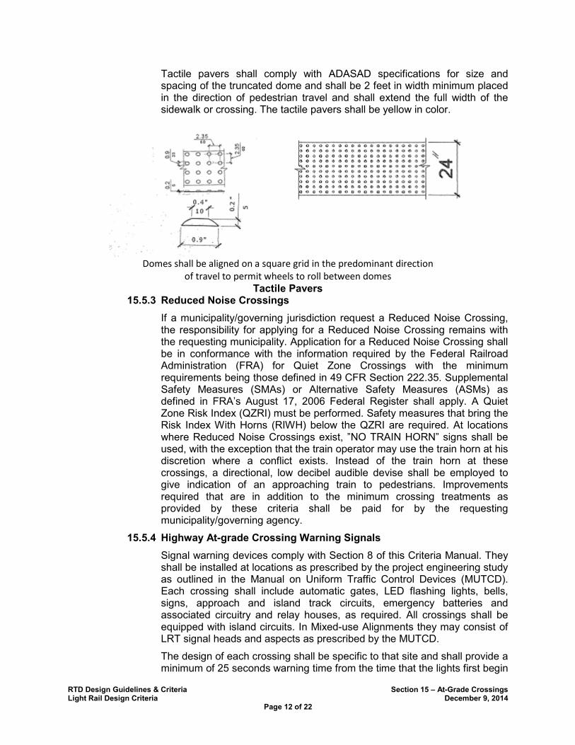
RTD Design Guidelines & Criteria Section 15 – At-Grade Crossings Light Rail Design Criteria December 9, 2014
Page 12 of 22
Tactile pavers shall comply with ADASAD specifications for size and spacing of the truncated dome and shall be 2 feet in width minimum placed in the direction of pedestrian travel and shall extend the full width of the sidewalk or crossing. The tactile pavers shall be yellow in color.
Domes shall be aligned on a square grid in the predominant direction
of travel to permit wheels to roll between domes
Tactile Pavers Reduced Noise Crossings 15.5.3
If a municipality/governing jurisdiction request a Reduced Noise Crossing, the responsibility for applying for a Reduced Noise Crossing remains with the requesting municipality. Application for a Reduced Noise Crossing shall be in conformance with the information required by the Federal Railroad Administration (FRA) for Quiet Zone Crossings with the minimum requirements being those defined in 49 CFR Section 222.35. Supplemental Safety Measures (SMAs) or Alternative Safety Measures (ASMs) as defined in FRA’s August 17, 2006 Federal Register shall apply. A Quiet Zone Risk Index (QZRI) must be performed. Safety measures that bring the Risk Index With Horns (RIWH) below the QZRI are required. At locations where Reduced Noise Crossings exist, ”NO TRAIN HORN” signs shall be used, with the exception that the train operator may use the train horn at his discretion where a conflict exists. Instead of the train horn at these crossings, a directional, low decibel audible devise shall be employed to give indication of an approaching train to pedestrians. Improvements required that are in addition to the minimum crossing treatments as provided by these criteria shall be paid for by the requesting municipality/governing agency.
Highway At-grade Crossing Warning Signals 15.5.4
Signal warning devices comply with Section 8 of this Criteria Manual. They shall be installed at locations as prescribed by the project engineering study as outlined in the Manual on Uniform Traffic Control Devices (MUTCD). Each crossing shall include automatic gates, LED flashing lights, bells, signs, approach and island track circuits, emergency batteries and associated circuitry and relay houses, as required. All crossings shall be equipped with island circuits. In Mixed-use Alignments they may consist of LRT signal heads and aspects as prescribed by the MUTCD.
The design of each crossing shall be specific to that site and shall provide a minimum of 25 seconds warning time from the time that the lights first begin
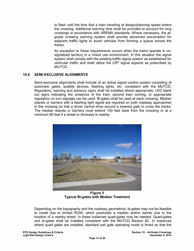
RTD Design Guidelines & Criteria Section 15 – At-Grade Crossings Light Rail Design Criteria December 9, 2014
Page 13 of 22
to flash until the time that a train traveling at design/planning speed enters the crossing. Additional warning time shall be provided to account for long crossings in accordance with AREMA standards. Where necessary, the at-grade crossing warning system shall provide advanced pre-emption for adjacent traffic lights to avoid vehicles from forming a queue across the tracks.
An exception to these requirements occurs when the trains operate in un-signalized territory in a mixed use environment. In this situation the signal system shall comply with the existing traffic signal system as established for vehicular traffic and shall utilize the LRT signal aspects as prescribed by MUTCD.
SEMI-EXCLUSIVE ALIGNMENTS 15.6
Semi-exclusive alignments shall include of an active signal control system consisting of automatic gates, audible devices, flashing lights, etc. consistent with the MUTCD. Regulatory, warning and advisory signs shall be installed where appropriate. LED blank out signs indicating the presence of the train, second train coming, or appropriate regulatory no turn signage can be used. Bi-gates shall be used at each crossing. Median islands or barriers with a flashing light signal are required on both roadway approaches to the crossing so that a driver cannot drive around a lowered gate to cross the tracks. The median islands or barriers must extend 100 feet back from the crossing or at a minimum 60 feet if a street or driveway is nearby.
Figure 5
Typical Bi-gates with Median Treatment
Depending on the topography and the roadway geometrics, bi-gates may not be feasible to install due to limited ROW, which precludes a median and/or barrier due to the location of a nearby street. In these instances quad-gates may be needed. Quad-gates and bi-gates shall be installed consistent with the MUTCD Section 8C. In instances where quad gates are installed, standard exit gate operating mode is timed so that the

RTD Design Guidelines & Criteria Section 15 – At-Grade Crossings Light Rail Design Criteria December 9, 2014
Page 14 of 22
exit gate comes down after the entrance gate in order to avoid entrapment of a vehicle within the LRT dynamic envelope. However, at crossings adjacent to traffic signals with busy roadway traffic where there is a chance for queuing of traffic through the intersection along the adjacent roadway to occur, the use of a dynamic exit gate operating mode may be required (with the use of presence detectors, etc.).
MIXED-USE ALIGNMENTS 15.7
Mixed-use alignments shall have active control treatments provided at each crossing. The crossing treatment shall consist of integrating the traffic control system for the roadway and pedestrian movements with a signal system specific for LRT traffic control signals that are used for LRT movements only. The signal system shall comply with MUTCD standards. Where a signal system exists, a separate system that is interconnected with the signal system consisting of LRT signal heads and aspects shall be installed. If there is no signal system at a cross street, a signal shall be installed that includes vehicular, pedestrian and LRT signal heads. Mixed use alignments will normally use the traffic signal system for control of the vehicular traffic in the street in conjunction with LRT signal heads for control of the LRT. Private crossings in a mixed use alignment shall have adequate warning devices, which alert cross traffic of an approaching train. This is usually provided by flashing warning lights and signage. Appropriate blank out signs shall be installed and shall restrict all turns while the train approaches and occupies the intersection. Additional blank out signs may be needed to indicate trains are “approaching” and “occupying the intersection” and “second train coming”. Crossing treatments should include tactile warning surfaces (for pedestrians), channeling pavement markings, and “Stop Here on Red”. Where two tracks are crossed a “# of Tracks” sign (R15-2 and a R15-8, or W10 series) shall be used. Additional signage and striping may be required, depending on the engineering study and the hazard analysis. Signage and pavement marking shall comply with Section 8 of the MUTCD. Additional channelization should also be considered for pedestrians.
Figure 6
Quad-gates
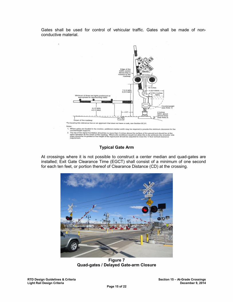
RTD Design Guidelines & Criteria Section 15 – At-Grade Crossings Light Rail Design Criteria December 9, 2014
Page 15 of 22
Gates shall be used for control of vehicular traffic. Gates shall be made of non-conductive material.
Typical Gate Arm
At crossings where it is not possible to construct a center median and quad-gates are installed; Exit Gate Clearance Time (EGCT) shall consist of a minimum of one second for each ten feet, or portion thereof of Clearance Distance (CD) at the crossing.
Figure 7
Quad-gates / Delayed Gate-arm Closure
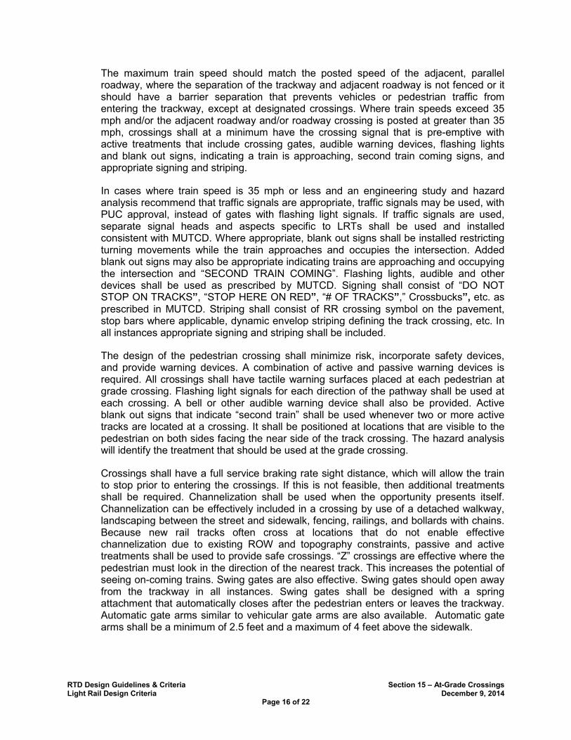
RTD Design Guidelines & Criteria Section 15 – At-Grade Crossings Light Rail Design Criteria December 9, 2014
Page 16 of 22
The maximum train speed should match the posted speed of the adjacent, parallel roadway, where the separation of the trackway and adjacent roadway is not fenced or it should have a barrier separation that prevents vehicles or pedestrian traffic from entering the trackway, except at designated crossings. Where train speeds exceed 35 mph and/or the adjacent roadway and/or roadway crossing is posted at greater than 35 mph, crossings shall at a minimum have the crossing signal that is pre-emptive with active treatments that include crossing gates, audible warning devices, flashing lights and blank out signs, indicating a train is approaching, second train coming signs, and appropriate signing and striping.
In cases where train speed is 35 mph or less and an engineering study and hazard analysis recommend that traffic signals are appropriate, traffic signals may be used, with PUC approval, instead of gates with flashing light signals. If traffic signals are used, separate signal heads and aspects specific to LRTs shall be used and installed consistent with MUTCD. Where appropriate, blank out signs shall be installed restricting turning movements while the train approaches and occupies the intersection. Added blank out signs may also be appropriate indicating trains are approaching and occupying the intersection and “SECOND TRAIN COMING”. Flashing lights, audible and other devices shall be used as prescribed by MUTCD. Signing shall consist of “DO NOT STOP ON TRACKS”, “STOP HERE ON RED”, “# OF TRACKS”,” Crossbucks”, etc. as prescribed in MUTCD. Striping shall consist of RR crossing symbol on the pavement, stop bars where applicable, dynamic envelop striping defining the track crossing, etc. In all instances appropriate signing and striping shall be included.
The design of the pedestrian crossing shall minimize risk, incorporate safety devices, and provide warning devices. A combination of active and passive warning devices is required. All crossings shall have tactile warning surfaces placed at each pedestrian at grade crossing. Flashing light signals for each direction of the pathway shall be used at each crossing. A bell or other audible warning device shall also be provided. Active blank out signs that indicate “second train” shall be used whenever two or more active tracks are located at a crossing. It shall be positioned at locations that are visible to the pedestrian on both sides facing the near side of the track crossing. The hazard analysis will identify the treatment that should be used at the grade crossing.
Crossings shall have a full service braking rate sight distance, which will allow the train to stop prior to entering the crossings. If this is not feasible, then additional treatments shall be required. Channelization shall be used when the opportunity presents itself. Channelization can be effectively included in a crossing by use of a detached walkway, landscaping between the street and sidewalk, fencing, railings, and bollards with chains. Because new rail tracks often cross at locations that do not enable effective channelization due to existing ROW and topography constraints, passive and active treatments shall be used to provide safe crossings. “Z” crossings are effective where the pedestrian must look in the direction of the nearest track. This increases the potential of seeing on-coming trains. Swing gates are also effective. Swing gates should open away from the trackway in all instances. Swing gates shall be designed with a spring attachment that automatically closes after the pedestrian enters or leaves the trackway. Automatic gate arms similar to vehicular gate arms are also available. Automatic gate arms shall be a minimum of 2.5 feet and a maximum of 4 feet above the sidewalk.
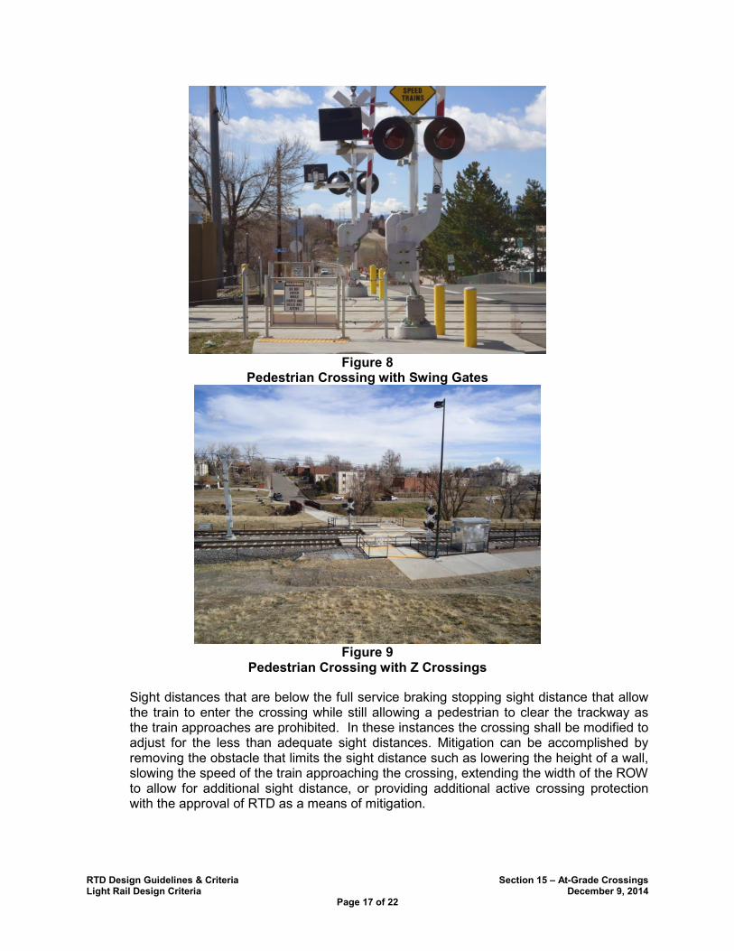
RTD Design Guidelines & Criteria Section 15 – At-Grade Crossings Light Rail Design Criteria December 9, 2014
Page 17 of 22
Figure 8
Pedestrian Crossing with Swing Gates
Figure 9
Pedestrian Crossing with Z Crossings
Sight distances that are below the full service braking stopping sight distance that allow the train to enter the crossing while still allowing a pedestrian to clear the trackway as the train approaches are prohibited. In these instances the crossing shall be modified to adjust for the less than adequate sight distances. Mitigation can be accomplished by removing the obstacle that limits the sight distance such as lowering the height of a wall, slowing the speed of the train approaching the crossing, extending the width of the ROW to allow for additional sight distance, or providing additional active crossing protection with the approval of RTD as a means of mitigation.

RTD Design Guidelines & Criteria Section 15 – At-Grade Crossings Light Rail Design Criteria December 9, 2014
Page 18 of 22
THIS PAGE LEFT INTENTIONALLY BLANK
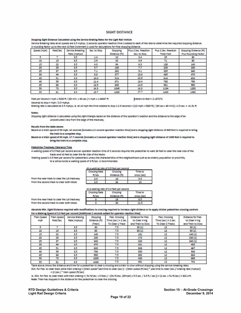
RTD Design Guidelines & Criteria Section 15 – At-Grade Crossings Light Rail Design Criteria December 9, 2014
Page 19 of 22
RTD Design Guidelines & Criteria Section 15 – At-Grade Crossings Light Rail Design Criteria December 9, 2014
Page 20 of 22
THIS PAGE LEFT INTENTIONALLY BLANK
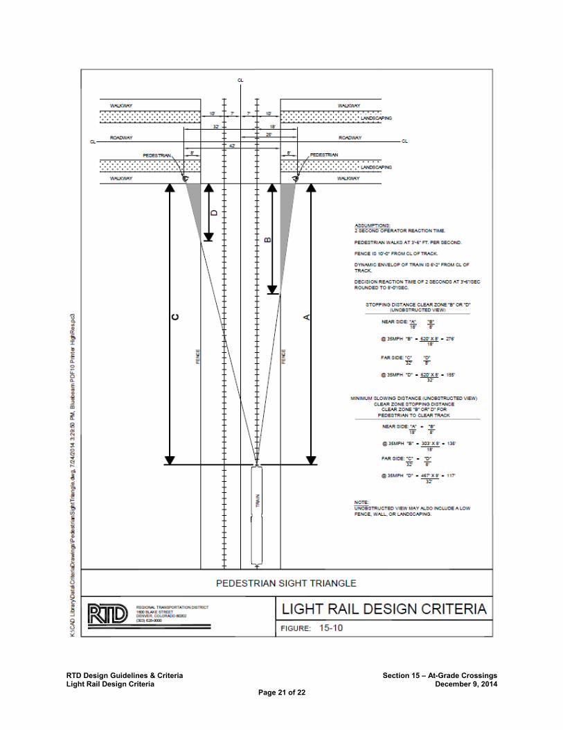
RTD Design Guidelines & Criteria Section 15 – At-Grade Crossings Light Rail Design Criteria December 9, 2014
Page 21 of 22

RTD Design Guidelines & Criteria Section 15 – At-Grade Crossings Light Rail Design Criteria December 9, 2014
Page 22 of 22
THIS PAGE LEFT INTENTIONALLY BLANK


