44
Introduction to Digital System Design RTL Hardware Design by P. Chu Chapter 1 1
| Date post: | 23-Dec-2015 |
| Category: |
Documents |
| Upload: | logan-cross |
| View: | 216 times |
| Download: | 0 times |
Chapter 1 1
Introduction to Digital System
Design
RTL Hardware Design by P. Chu

Chapter 1 2
1. Why Digital?2. Device Technologies3. System Representation4. Abstraction5. Development Tasks6. Development Flow
RTL Hardware Design by P. Chu
Outline
Chapter 1 3
1. Why Digital
RTL Hardware Design by P. Chu

Chapter 1 4
Advantage of digital devices ◦ Reproducibility of information◦ Flexibility and functionality: easier to store,
transmit and manipulate information◦ Economy: cheaper device and easier to design
Moore’s law◦ Transistor geometry◦ Chips double its density (number of transistor)
in every 18 months◦ Devices become smaller, faster and cheaper◦ Now a chip consists of hundreds of million gates◦ And we can have a “wireless-PDA-MP3-player-
camera-GPS-cell-phone” gadget very soon
RTL Hardware Design by P. Chu
Advantages
Chapter 1 5
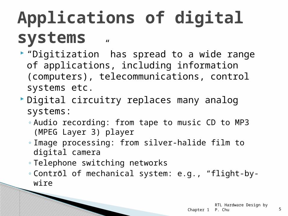
“Digitization” has spread to a wide range of applications, including information (computers), telecommunications, control systems etc.
Digital circuitry replaces many analog systems:◦ Audio recording: from tape to music CD to MP3
(MPEG Layer 3) player◦ Image processing: from silver-halide film to digital
camera ◦ Telephone switching networks◦ Control of mechanical system: e.g., “flight-by-wire”
RTL Hardware Design by P. Chu
Applications of digital systems

Chapter 1 6RTL Hardware Design by P. Chu
e.g, digital circuit in a wireless communication system
A/D
Datacompression
Dataencryption
Errorcorrection
codingModulationinfo
transmitter
digital implementation
D/A
Data de-compression
Datadecryption
Errorcorrectionde-coding
De-modulation
info
receiver
digital implementation
Chapter 1 7RTL Hardware Design by P. Chu
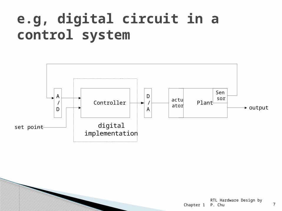
e.g, digital circuit in a control system
Plantoutput
D/A
ControllerA/D
Sensor
set point digitalimplementation
actuator
Chapter 1 8
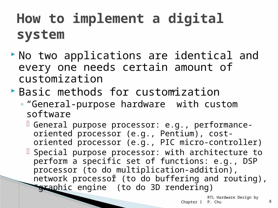
No two applications are identical and every one needs certain amount of customization
Basic methods for customization◦ “General-purpose hardware” with custom software
General purpose processor: e.g., performance-oriented processor (e.g., Pentium), cost-oriented processor (e.g., PIC micro-controller)
Special purpose processor: with architecture to perform a specific set of functions: e.g., DSP processor (to do multiplication-addition), network processor (to do buffering and routing), “graphic engine” (to do 3D rendering)
RTL Hardware Design by P. Chu
How to implement a digital system
Chapter 1 9
◦ Custom hardware◦ Custom software on a custom processor (known
as hardware-software co-design) Trade-off between Programmability,
Coverage, Cost, Performance, and Power consumption
A complex application contains many different tasks and use more than one customization methods
RTL Hardware Design by P. Chu
Chapter 1 10
2. Device Technologies
RTL Hardware Design by P. Chu
Chapter 1 11
Transistors and connection are made from many layers (typical 10 to 15 in CMOS) built on top of one another
Each layer has a special pattern defined by a mask One important aspect of an IC is the length of a
smallest transistor that can be fabricated◦ It is measured in micron (mm, 10-6 meter)◦ E.g., we may say an IC is built with 0.50 mm process◦ The process continues to improve, as witnessed by
Moore’s law◦ The state-of-art process approaches less than
a fraction of 0.1 mm (known as deep sub-micron)
RTL Hardware Design by P. Chu
Fabrication of an IC
Chapter 1 12
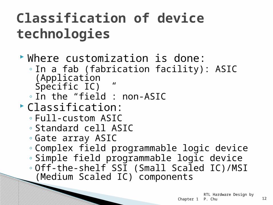
Where customization is done:◦ In a fab (fabrication facility): ASIC (Application
Specific IC) ◦ In the “field”: non-ASIC
Classification:◦ Full-custom ASIC◦ Standard cell ASIC◦ Gate array ASIC◦ Complex field programmable logic device◦ Simple field programmable logic device◦ Off-the-shelf SSI (Small Scaled IC)/MSI (Medium
Scaled IC) components
RTL Hardware Design by P. Chu
Classification of device technologies

Chapter 1 13
All aspects (e.g., size of a transistor) of a circuit are tailored for a particular application.
Circuit fully optimized Design extremely complex and involved Only feasible for small components Masks needed for all layers
RTL Hardware Design by P. Chu
Full-custom ASIC
Chapter 1 14
Circuit made of a set of pre-defined logic, known as standard cells
E.g., basic logic gates, 1-bit adder, D FF etc Layout of a cell is pre-determined, but layout of
the complete circuit is customized Masks needed for all layers
RTL Hardware Design by P. Chu
Standard-Cell ASIC

Chapter 1 15
Circuit is built from an array of a single type of cell (known as base cell)
Base cells are pre-arranged and placed in fixed positions, aligned as one- or two-dimensional array
More sophisticated components (macro cells) can be constructed from base cells
Masks needed only for metal layers (connection wires)
RTL Hardware Design by P. Chu
Gate array ASIC

Chapter 1 16
Device consists of an array of generic logic cells and general interconnect structure
Logic cells and interconnect can be “programmed” by utilizing “semiconductor fuses or “switches”
Customization is done “in the filed” Two categories:
◦ CPLD (Complex Programmable Logic Device)◦ FPGA (Field Programmable Gate Array)
No custom mask needed
RTL Hardware Design by P. Chu
Complex Field Programmable Device
Chapter 1 17
Programmable device with simple internal structure
E.g., ◦ PROM (Programmable Read Only Memory)◦ PAL (Programmable Array Logic)
No custom mask needed Replaced by CPLD/FPGA
RTL Hardware Design by P. Chu
Simple Field Programmable Device
Chapter 1 18
Small parts with fixed, limited functionality E.g., 7400 TTL series (more than 100 parts) Resource (e.g., power, board area,
manufacturing cost etc.) is consumed by “package” but not “silicon”
No longer a viable option
RTL Hardware Design by P. Chu
SSI/MSI components
Chapter 1 19
Standard Cell ASIC Gate Array ASIC FPGA/CPLD
RTL Hardware Design by P. Chu
Three viable technologies

Chapter 1 20
Area (Size): silicon “real-estate”◦ Standard cell is the smallest since the cells
and interconnect are customized◦ FPGA is the largest
Overhead for “programmability” Capacity cannot be completely utilized
Speed (Performance)◦ Time required to perform a task
Power Cost
RTL Hardware Design by P. Chu
Comparison of technology
Chapter 1 21
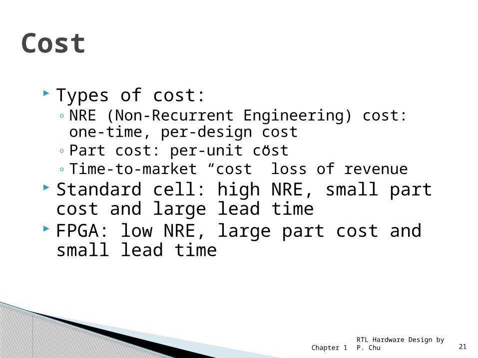
Types of cost:◦ NRE (Non-Recurrent Engineering) cost: one-
time, per-design cost◦ Part cost: per-unit cost◦ Time-to-market “cost” loss of revenue
Standard cell: high NRE, small part cost and large lead time
FPGA: low NRE, large part cost and small lead time
RTL Hardware Design by P. Chu
Cost

Chapter 1 22RTL Hardware Design by P. Chu
Graph of per-unit cost
Chapter 1 23RTL Hardware Design by P. Chu
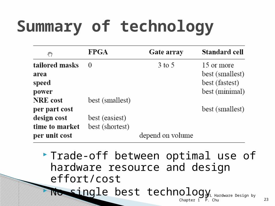
Summary of technology
Trade-off between optimal use of hardware resource and design effort/cost
No single best technology
Chapter 1 24
3. System Representation
(View)
RTL Hardware Design by P. Chu

Chapter 1 25
View: different perspectives of a system Behavioral view:
◦ Describe functionalities and i/o behavior◦ Treat the system as a black box
Structural view:◦ Describe the internal implementation
(components and interconnections)◦ Essentially block diagram
Physical view:◦ Add more info to structural view: component size,
component locations, routing wires◦ E.g., layout of a print circuit board
RTL Hardware Design by P. Chu

Chapter 1 26RTL Hardware Design by P. Chu
e.g., structural and physical view
Chapter 1 27
4. Abstraction
RTL Hardware Design by P. Chu

Chapter 1 28
How to manage complexity for a chip with 10 million transistors?
Abstraction: simplified model of a system◦ show the selected features ◦ Ignore associated detail
E.g., timing of an inverter
RTL Hardware Design by P. Chu

Chapter 1 29
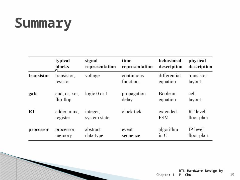
Level of abstractions◦ Transistor level ◦ Gate level◦ Register transfer (RT) level◦ Processor level
Characteristics of each level◦ Basic building blocks◦ Signal representation◦ Time representation◦ Behavioral representation◦ Physical representation.
RTL Hardware Design by P. Chu
Chapter 1 30RTL Hardware Design by P. Chu
Summary

Chapter 1 31
RT (Register Transfer) is a misleading term Should use “module-level” Two meanings:
◦ Loosely: represent the module level◦ Formally: a design methodology in which the
system operation is described by how the data is manipulated and moved among registers
RTL Hardware Design by P. Chu
RT level
Chapter 1 32RTL Hardware Design by P. Chu
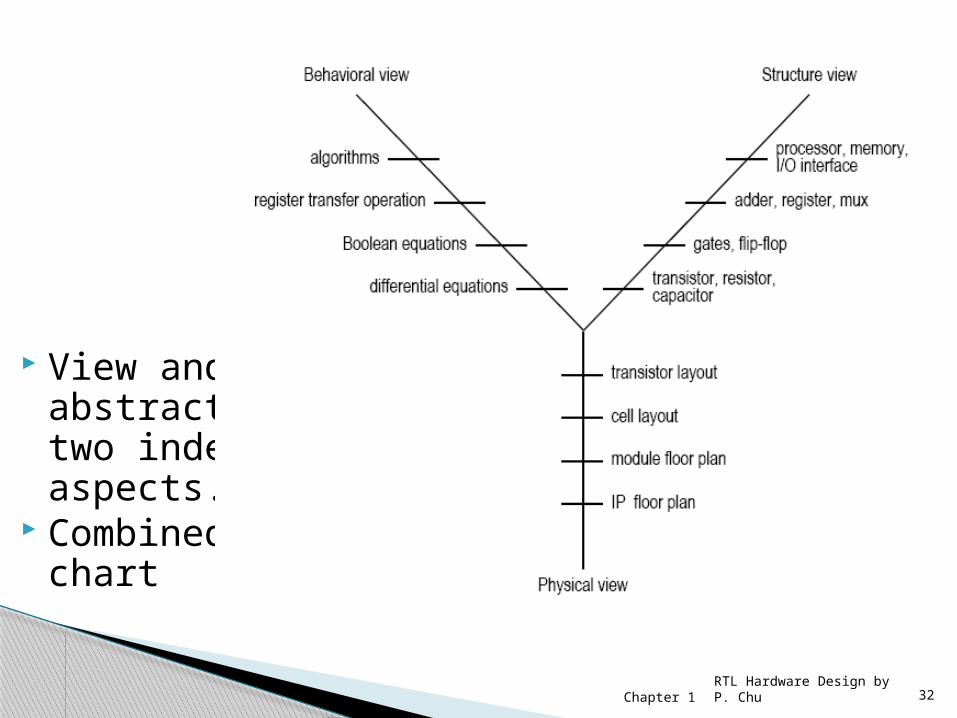
View and abstraction are two independent aspects.
Combined in a Y-chart

Chapter 1 33
5. Development Tasks
RTL Hardware Design by P. Chu

Chapter 1 34
Developing a digital system is a refining and validating process
Main tasks:◦ Synthesis◦ Physical design◦ Verification◦ Testing
RTL Hardware Design by P. Chu

Chapter 1 35
A refinement process that realizes a description with components from the lower abstraction level.
The resulting description is a structural view in the lower abstraction level
Type of synthesis:◦ High-level synthesis◦ RT level synthesis◦ Gate level synthesis◦ Technology mapping
RTL Hardware Design by P. Chu
Synthesis
Chapter 1 36
Placement and routing◦ Refining from structural view to physical view◦ Derive lay out of a netlist
Circuit extraction:◦ Determine the wire resistance of capacitance
Others◦ Derivation of power grid and clock distribution
network, assurance of signal integrity etc.
RTL Hardware Design by P. Chu
Physical Design
Chapter 1 37
Check whether a design meets the specification and performance goals.
Concern the correctness of the initial design and the refinement processes
Two aspects◦ Functionality◦ Performance (timing)
RTL Hardware Design by P. Chu
Verification
Chapter 1 38
Simulation◦ spot check: cannot verify the absence of errors◦ Can be computation inensive
Timing analysis◦ Just check delay
Formal verification◦ apply formal math techniques determine its
property◦ E.g, equivalence checking
Hardware emulation
RTL Hardware Design by P. Chu
Method of Verification
Chapter 1 39
Testing is the process of detecting physical defects of a die or a package occurred at the time of manufacturing
Testing and verification are different tasks. Difficult for large circuit
◦ Need to add auxiliary testing circuit in design◦ E.g., built-in self test (BIST), scan chain etc.
RTL Hardware Design by P. Chu
Testing
Chapter 1 40
EDA (Electronic Design Automation) EDA software can automate some tasks Can software replace human hardware
designer? (e.g., C-program to chip) Synthesis software
◦ should be treated as a tool to perform transformation and local optimization
◦ cannot alter the original architecture or convert a poor design into a good one
RTL Hardware Design by P. Chu
Limitation of EDA software

Chapter 1 41
Development Flow
RTL Hardware Design by P. Chu
Chapter 1 42
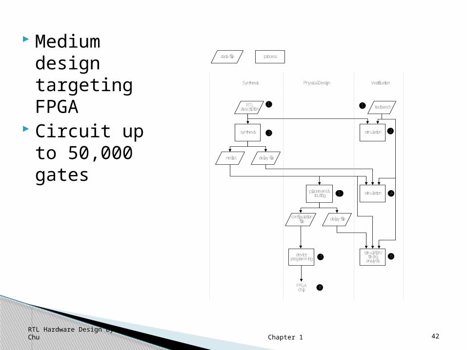
Medium design targeting FPGA
Circuit up to 50,000 gates
synthesis
placement & routing
device programming
FPGAchip
simulation
simulation
simulation/timing
analysis
Synthesis Physical Design Verification
data file process
RTL description
netlist delay file
configuration file delay file
testbench1 1
23
445
67
8
RTL Hardware Design by P. Chu

Chapter 1 43
Large design targeting FPGA◦ Design partition◦ More verification
Large design targeting ASIC◦ Thorough verification◦ Testing ◦ Physical design
RTL Hardware Design by P. Chu
Additional tasks

Chapter 1 44
Goal: ◦ Systematically develop efficient, portable RT
level designs that can be easily integrated into a larger system
Design for efficiency Design for “large”
◦ Large module, large system, overall development process
Design for portability◦ Device independent, software dependent,
design reuse
RTL Hardware Design by P. Chu
Goal of this course


