15

INDEX
F6–2
SelectionSelection Process................................................... F6-2Service Factor Table ............................................... F6-3Standard Bore Tolerances ...................................... F6-4
C SeriesContinuous Sleeve Gear Coupling .......................... F6-5
F SeriesFull Flex .................................................................. F6-6Flex Rigid ............................................................... F6-7Floating Shaft ......................................................... F6-7Flange Details ......................................................... F6-8Short Slide ............................................................. F6-9Mill Motor .............................................................. F6-10Limited End Float ................................................... F6-11Vertical Type........................................................... F6-12Stock Spacers, F, MXB, or K100 Series.................. F6-13
Deck-Flex and Deck-Flex Mite ....................................... F6-14
OrderingStandard gear coupling product is sold by component
See examples on individual pages
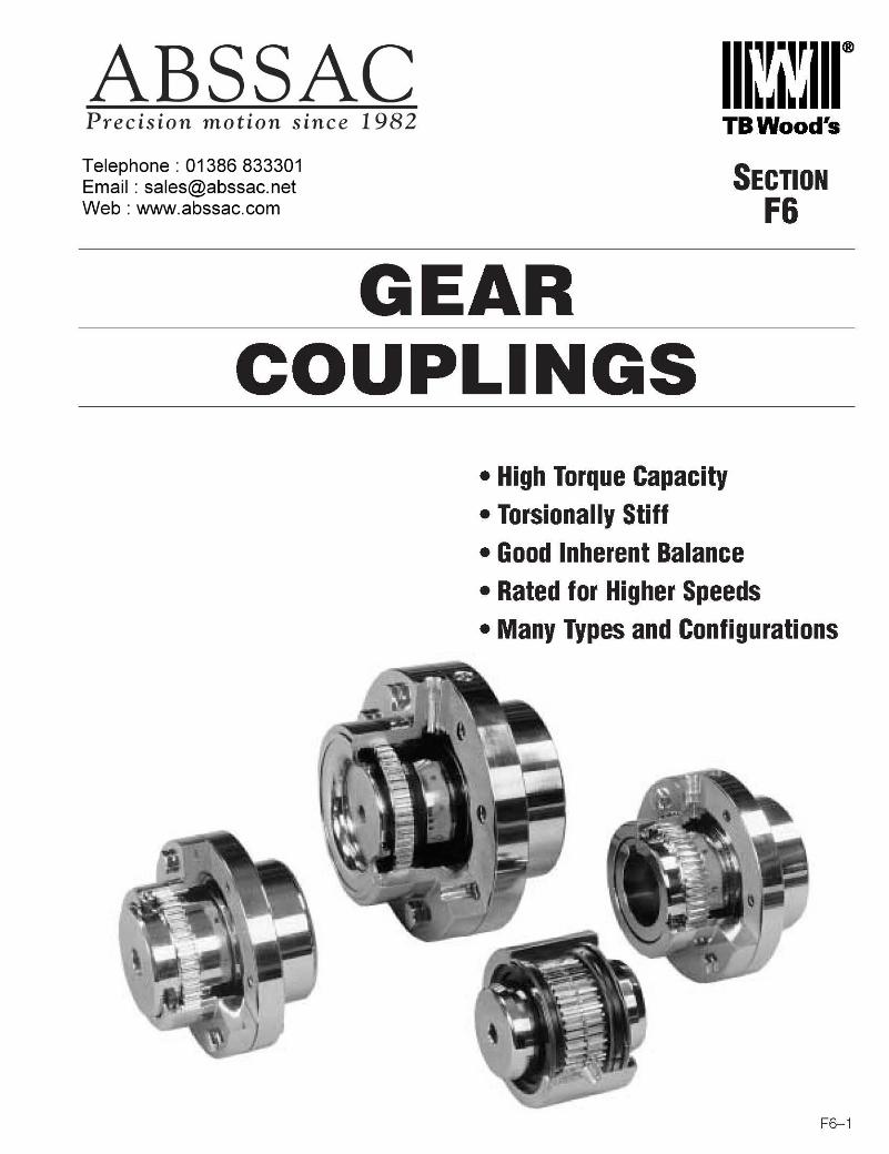
GEAR COUPLING SELECTION
Calculate Design Horsepower or Design Torque
• If HP and RPM are Known, Calculate Design HP@100 RPM
Design HP@100 RPM=(Prime mover HP x Service Factor x 100) divided by the Coupling RPM
Refer to the HP@100 RPM rating for the coupling style desired. Select the coupling equal to or greater than thecalculated design HP@100 RPM. Check the maximum bore capabilities to be sure the size coupling you havechosen is capable of your largest bore.
• If Using Prime Mover Torque, Calculate Design Torque
Design Torque = Prime Mover Torque x Service Factor
Refer to torque rating in the coupling style desired. Select the coupling equal to or greater than the calculateddesign torque. Check the maximum bore capabilities to be sure the size coupling you have chosen is capable ofyour largest bore.
The above selection can be used for all series of industrial gear couplings, however, the Deck-Flex andDeck-Flex Mite couplings have their own calculations.
GEAR COUPLING SELECTION
F6–3
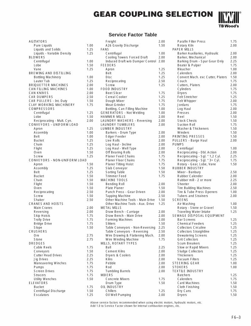
AGITATORSPure Liquids 1.00Liquids and Solids 1.25Liquids - Variable Density 1.25
BLOWERSCentrifugal 1.00Lobe 1.50Vane 1.25
BREWING AND DISTILLINGBottling Machinery 1.00Lauter Tub 1.25
BRIQUETTER MACHINES 2.00CAN FILLING MACHINES 1.00CAN KNIVES 2.00CAR DUMPERS 2.50CAR PULLERS - Int. Duty 1.50CLAY WORKING MACHINERY 1.75COMPRESSORS
Centrifugal 1.25Lobe 1.50Reciprocating - Mult. Cyn. 2.00
CONVEYORS - UNIFORM LOADApron 1.25Assembly 1.00Belt 1.00Bucket 1.25Chain 1.25Flight 1.25Oven 1.50Screw 1.25
CONVEYORS - NON-UNIFORM LOADApron 1.50Assembly 1.25Belt 1.25Bucket 1.50Chain 1.50Flight 1.50Oven 1.50Reciprocating 2.50Screw 1.50Shaker 2.50
CRANES AND HOISTSMain Cranes 2.00Reversing 2.00Skip Hoists 1.75Trolly Drive 1.75Bridge Drive 1.75Slope 1.50
CRUSHERSOre 2.75Stone 2.75
DREDGESCable Reels 1.75Conveyors 1.50Cutter Head Drives 2.25Jig Drives 2.25Maneuvering Winches 1.75Pumps 1.75Screen Drives 1.75Stracers 1.75Utility Wenches 1.50
ELEVATORSBucket 1.75Centrifugal Discharge 1.50Escalators 1.25
Freight 2.00A26 Gravity Discharge 1.50
FANSCentrifugal 1.00Cooling Towers Forced Draft 2.00Induced Draft w/o Damper Control 2.00
FEEDERSApron 1.25Belt 1.25Disc 1.25Reciprocating 2.50Screw 1.25
FOOD INDUSTRYBeet Slicer 1.75Cereal Cooker 1.25Dough Mixer 1.75Meat Grinder 1.75Bottling, Can Filling Machine 1.00
GENERATORS - Not Welding 1.00HAMMER MILLS 2.00LAUNDRY WASHERS - Reversing 2.00LAUNDRY TUMBLERS 2.00LUMBER INDUSTRY
Barkers - Drum Type 2.00Edger Feeder 2.00Live Rolls 2.00Log Haul - Incline 2.00Log Haul - Well Type 2.00Off Bearing Rolls 2.00Planer Feed Chains 1.75Planer Floor Chains 1.75Planer Tilting Hoist 1.75Slab Conveyor 1.50Sorting Table 1.50Trimmer Feed 1.75
MACHINE TOOLSBending Roll 2.00Plate Planer 1.50Punch Press - Gear Driven 2.00Tapping Machine 2.50Other Machine Tools - Main Drive 1.50Other Machine Tools - Aux. Drive 1.25
METAL MILLSDraw Bench - Carriage 2.00Draw Bench - Main Drive 2.00Forming Machines 2.00Slitters 1.50Table Conveyors - Non-Reversing 2.25Table Conveyors - Reversing 2.50Wire Drawing & Flattening Mach. 2.00Wire Winding Machine 1.75
MILLS, ROTARY TYPESBall 2.25Cement Kilns 2.00Dryers & Coolers 2.00Kilns 2.00Pebble 2.00Rod 2.00Tumbling Barrels 2.00
MIXERSConcrete Mixers 1.75Drum Type 1.50
OIL INDUSTRYChillers 1.25Oil Well Pumping 2.00
Parafin Filter Press 1.75Rotary Kiln 2.00
PAPER MILLSBarker Auxiliaries, Hydraulic 2.00Barker, Mechanical 2.00Barking Drum - Spur Gear Only 2.25Beater & Pulper 1.75Bleacher 1.00Calenders 2.00Convert Mach. exc Cutter, Platers 1.50Couch 1.75Cutters, Platers 2.00Cylinders 1.75Dryers 1.75Felt Stretcher 1.25Felt Whipper 2.00Jordans 1.75Log Haul 2.00Presses 2.00Reel 1.50Stock Chests 1.50Suction Roll 1.75Washer & Thickeners 1.50Winders 1.50
PRINTING PRESSES 1.50PULLERS - Barge Haul 2.00PUMPS
Centrifugal 1.00Reciprocating - Dbl. Action 2.00Reciprocating - Sgl. “ 1,2 Cyl. 2.25Reciprocating - Sgl. “ 3+ Cyl. 1.75Rotary - Gear, Lobe, Vane 1.50
RUBBER INDUSTRYMixer - Banbury 2.50Rubber Calender 2.00Rubber mill - 2 or more 2.25Sheeter 2.00Tire Building Machines 2.50Tire & Tube Press Openers 1.00Tubers and Strainers 2.00
SCREENSAir Washing 1.00Rotary - Stone or Gravel 1.50Traveling Water Intake 1.25
SEWAGE DISPOSAL EQUIPMENTBar Screens 1.25Chemical Feeders 1.25Collectors Circuline 1.25Collectors Straightline 1.25Dewatering Screens 1.25Grit Collectors 1.25Scum Breakers 1.25Slow or Rapid Mixers 1.25Sludge Collectors 1.25Thickeners 1.25Vacuum Filters 1.25
STEERING GEAR 1.00STOKERS 1.00TEXTILE INDUSTRY
Batchers 1.25Calenders 1.75Card Machines 1.50Cloth Finishing 1.50Dry Cans 1.75Dryers 1.50
Service Factor Table
Above service factors recommended when using electric motors, hydraulic motors, etc. Add 1.0 to Service Factor shown for internal combustion engines, etc.
STANDARD BORE TOLERANCES
F6–4
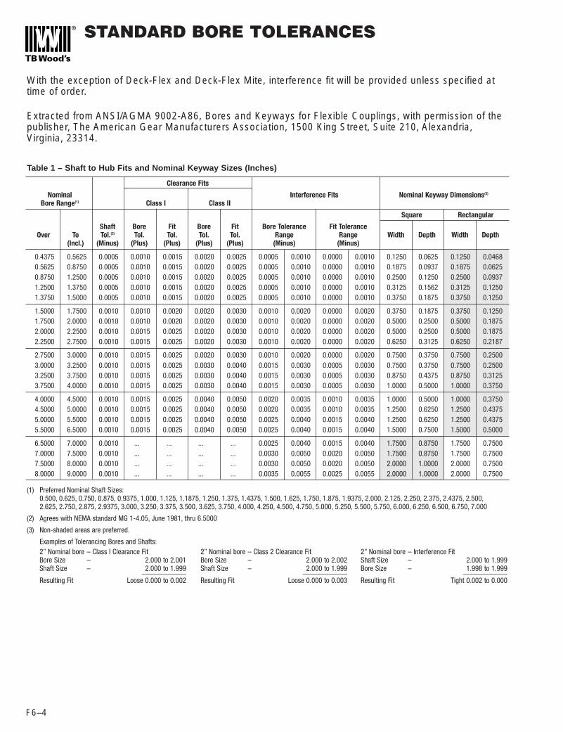
Clearance Fits
Nominal Interference Fits Nominal Keyway Dimensions(3)
Bore Range(1) Class I Class II
Square Rectangular
Shaft Bore Fit Bore Fit Bore Tolerance Fit ToleranceOver To Tol.(2) Tol. Tol. Tol. Tol. Range Range Width Depth Width Depth
(Incl.) (Minus) (Plus) (Plus) (Plus) (Plus) (Minus) (Minus)
With the exception of Deck-Flex and Deck-Flex Mite, interference fit will be provided unless specified attime of order.
Extracted from ANSI/AGMA 9002-A86, Bores and Keyways for Flexible Couplings, with permission of thepublisher, The American Gear Manufacturers Association, 1500 King Street, Suite 210, Alexandria,Virginia, 23314.
Table 1 – Shaft to Hub Fits and Nominal Keyway Sizes (Inches)
0.4375 0.5625 0.0005 0.0010 0.0015 0.0020 0.0025 0.0005 0.0010 0.0000 0.0010 0.1250 0.0625 0.1250 0.04680.5625 0.8750 0.0005 0.0010 0.0015 0.0020 0.0025 0.0005 0.0010 0.0000 0.0010 0.1875 0.0937 0.1875 0.06250.8750 1.2500 0.0005 0.0010 0.0015 0.0020 0.0025 0.0005 0.0010 0.0000 0.0010 0.2500 0.1250 0.2500 0.09371.2500 1.3750 0.0005 0.0010 0.0015 0.0020 0.0025 0.0005 0.0010 0.0000 0.0010 0.3125 0.1562 0.3125 0.12501.3750 1.5000 0.0005 0.0010 0.0015 0.0020 0.0025 0.0005 0.0010 0.0000 0.0010 0.3750 0.1875 0.3750 0.1250
1.5000 1.7500 0.0010 0.0010 0.0020 0.0020 0.0030 0.0010 0.0020 0.0000 0.0020 0.3750 0.1875 0.3750 0.12501.7500 2.0000 0.0010 0.0010 0.0020 0.0020 0.0030 0.0010 0.0020 0.0000 0.0020 0.5000 0.2500 0.5000 0.18752.0000 2.2500 0.0010 0.0015 0.0025 0.0020 0.0030 0.0010 0.0020 0.0000 0.0020 0.5000 0.2500 0.5000 0.18752.2500 2.7500 0.0010 0.0015 0.0025 0.0020 0.0030 0.0010 0.0020 0.0000 0.0020 0.6250 0.3125 0.6250 0.2187
2.7500 3.0000 0.0010 0.0015 0.0025 0.0020 0.0030 0.0010 0.0020 0.0000 0.0020 0.7500 0.3750 0.7500 0.25003.0000 3.2500 0.0010 0.0015 0.0025 0.0030 0.0040 0.0015 0.0030 0.0005 0.0030 0.7500 0.3750 0.7500 0.25003.2500 3.7500 0.0010 0.0015 0.0025 0.0030 0.0040 0.0015 0.0030 0.0005 0.0030 0.8750 0.4375 0.8750 0.31253.7500 4.0000 0.0010 0.0015 0.0025 0.0030 0.0040 0.0015 0.0030 0.0005 0.0030 1.0000 0.5000 1.0000 0.3750
4.0000 4.5000 0.0010 0.0015 0.0025 0.0040 0.0050 0.0020 0.0035 0.0010 0.0035 1.0000 0.5000 1.0000 0.37504.5000 5.0000 0.0010 0.0015 0.0025 0.0040 0.0050 0.0020 0.0035 0.0010 0.0035 1.2500 0.6250 1.2500 0.43755.0000 5.5000 0.0010 0.0015 0.0025 0.0040 0.0050 0.0025 0.0040 0.0015 0.0040 1.2500 0.6250 1.2500 0.43755.5000 6.5000 0.0010 0.0015 0.0025 0.0040 0.0050 0.0025 0.0040 0.0015 0.0040 1.5000 0.7500 1.5000 0.5000
6.5000 7.0000 0.0010 ... ... ... ... 0.0025 0.0040 0.0015 0.0040 1.7500 0.8750 1.7500 0.75007.0000 7.5000 0.0010 ... ... ... ... 0.0030 0.0050 0.0020 0.0050 1.7500 0.8750 1.7500 0.75007.5000 8.0000 0.0010 ... ... ... ... 0.0030 0.0050 0.0020 0.0050 2.0000 1.0000 2.0000 0.75008.0000 9.0000 0.0010 ... ... ... ... 0.0035 0.0055 0.0025 0.0055 2.0000 1.0000 2.0000 0.7500
(1) Preferred Nominal Shaft Sizes:0.500, 0.625, 0.750, 0.875, 0.9375, 1.000, 1.125, 1.1875, 1.250, 1.375, 1.4375, 1.500, 1.625, 1.750, 1.875, 1.9375, 2.000, 2.125, 2.250, 2.375, 2.4375, 2.500,2.625, 2.750, 2.875, 2.9375, 3.000, 3.250, 3.375, 3.500, 3.625, 3.750, 4.000, 4.250, 4.500, 4.750, 5.000, 5.250, 5.500, 5.750, 6.000, 6.250, 6.500, 6.750, 7.000
(2) Agrees with NEMA standard MG 1-4.05, June 1981, thru 6.5000
(3) Non-shaded areas are preferred.
Examples of Tolerancing Bores and Shafts:2” Nominal bore – Class I Clearance FitBore Size – 2.000 to 2.001Shaft Size – 2.000 to 1.999____________Resulting Fit Loose 0.000 to 0.002
2” Nominal bore – Class 2 Clearance FitBore Size – 2.000 to 2.002Shaft Size – 2.000 to 1.999____________Resulting Fit Loose 0.000 to 0.003
2” Nominal bore – Interference FitShaft Size – 2.000 to 1.999Bore Size – 1.998 to 1.999____________Resulting Fit Tight 0.002 to 0.000

C SERIES CONTINUOUS SLEEVE GEARCOUPLING
F6–5
Two Hubs-One Sleeve-High quality carbon steel
One Accessory Kit -This contains
two BUNA N sealsand two retaining rings.
Approx.Wt. (Lbs.)
Size A B C D E F G G1 H (1) J K Solid Bore7/8 3.31 3.12 2.00 2.00 1.50 1.00 0.12 0.38 3.75 0.12 1.94 5
1-1/2 3.75 3.75 2.53 2.38 1.81 1.27 0.12 0.50 4.59 0.19 2.25 82 4.75 4.25 2.56 3.25 2.06 1.28 0.12 0.50 4.88 0.19 3.00 13
2-1/2 5.50 4.75 3.06 3.94 2.25 1.53 0.25 0.75 5.72 0.25 3.75 203 6.62 5.50 3.75 4.75 2.62 1.88 0.25 0.75 6.88 0.25 4.75 33
3-1/2 7.50 8.75 4.00 5.38 4.25 2.00 0.25 0.75 9.25 0.25 5.50 634 8.75 9.00 4.62 6.25 4.38 2.31 0.25 0.75 9.50 0.25 6.50 91
4-1/2 9.50 10.25 4.88 7.25 5.00 2.44 0.25 0.75 10.38 0.25 7.25 1265 10.75 12.25 5.75 8.25 6.00 2.88 0.25 0.75 12.25 0.25 8.12 1956 12.25 13.00 6.50 9.50 6.38 3.25 0.25 0.75 13.38 0.25 9.25 2677 14.00 14.88 7.50 10.50 7.25 3.75 0.38 0.88 15.38 0.25 9.75 3209 16.25 19.00 8.12 12.62 9.25 4.06 0.50 1.00 19.00 0.25 12.50 52011 19.25 22.50 8.12 15.62 11.00 4.06 0.50 1.00 22.50 0.25 15.50 92512 20.50 25.00 8.38 16.50 12.25 4.19 0.50 1.00 25.00 0.25 16.00 1200
Puller holes are optionalSetscrews are optional.
STANDARD DIMENSIONS
RATINGS
(3)HP @ TORQUE MIN MAX MAX MAX ANGULAR PARALLEL
SIZE 100 RPM in. lbs. BORE BORE RPM RPM DEGREES INSTD KEY UNBALANCED BALANCED PER MESH INCHES (2)
7/8 4 2520 0.44 1.25 6000 18000 0.50 0.0051-1/2 12 7560 0.44 1.62 5000 15000 0.50 0.007
2 32 20160 0.56 2.12 4200 12600 0.50 0.0072-1/2 48 30240 0.81 2.62 3750 11250 0.50 0.010
3 80 50400 1.19 3.12 3000 9000 0.50 0.0123-1/2 140 88200 1.56 3.62 2800 8400 0.50 0.012
4 200 126000 1.81 4.12 2400 7200 0.25 0.0074-1/2 292 183960 1.81 4.75 2200 6600 0.25 0.007
5 430 270900 2.56 5.75 2100 0.25 0.0096 600 378000 4.06 6.62 2000 0.25 0.0107 950 598500 4.56 7.50 1000 0.25 0.0119 2000 1260000 5.94 9.50 800 Consult 0.25 0.01311 3500 2205900 7.81 11.50 600 Factory 0.25 0.01412 4000 2520000 9.81 12.50 550 0.25 0.014
Standard Full FlexDouble Engagement (C)
Flex-RigidSingle Engagement (CFR)
MISALIGNMENT
Below is an ordering example of a Flex Rigid 4 C CouplingItem (Qty) Part Number DescriptionFlex Hub (1) G4CRB 4 C Rough Bore Flex HubRigid Hub (1) G4CRRB 4 C Rough Bore Rigid HubSleeve (1) G4CS 4 C Sleeve Accessory Kit (1) G4CAK Seals & Lockrings for C4 Coupling
Below is an ordering example of a Full Flex 4 C CouplingItem (Qty) Part Number DescriptionFlex Hub (2) G4CRB 4 C Rough Bore Flex HubSleeve (1) G4CS 4 C Sleeve Accessory Kit (1) G4CAK Seals & Lockrings for C4 Coupling
*When ordering please specify bore diameter with tolerances for both hubs, keyway sizes, set screws if applicable,speed, horsepower, and application details.
(1) “H” dimension required for installation(2) Flex Rigid configuration handles only angular misalignment.(3) Balance requires the manufacture of 2 special flexible hubs.

F SERIES FLANGED SLEEVE GEARCOUPLINGS
F6–6
Ordering Couplings are sold by component.
Two Sleeves Two HubsHigh quality carbon steel High quality carbon steel
Exposed and Shrouded Bolt Design
One Accessory KitGasket and Hardware
• Exposed bolt design isstandard on all sizes.
• Puller holes are optional.
• Shrouded bolt design isavailable on size 1through 5 when specified.
• Shrouded bolt style;hardware is recessed incounter bored holes.
Item (Qty) Part Number Description
Flex Hubs (2) G4FRB 4F Rough Bore Flex Hubs
G4FSEB or 4F Sleeve with Exposed BoltsSleeves (2) G4FSSB 4F Sleeve with Shrouded Bolts
G4AEB or Hardware and Gasket for 4F with Exposed BoltsAccessory Kit (1) G4ASB Hardware and Gasket for 4F with Shrouded Bolts
Below is an ordering example of a 4F coupling.
Size A B C D E G H (1)
Max. Parallel Misalign-ment (4)
Approx. Wt.(Lbs.) Solid Bore
1 4.56 3.50 3.00 2.31 1.69 0.12 4.19 0.055 91 1/2 6.00 4.00 3.88 3.00 1.94 0.12 4.75 0.060 19
2 7.00 5.00 4.81 4.00 2.44 0.12 6.00 0.085 342 1/2 8.38 6.25 5.81 4.62 3.03 0.19 7.12 0.105 55
3 9.44 7.38 6.81 5.62 3.59 0.19 8.12 0.115 863 1/2 11.00 8.62 7.84 6.50 4.19 0.25 9.38 0.130 135
4 12.50 9.75 9.19 7.50 4.75 0.25 10.25 0.150 1954 1/2 13.62 10.94 10.31 8.50 5.31 0.31 11.50 0.175 268
5 15.31 12.38 11.44 9.50 6.03 0.31 13.00 0.200 3945 1/2 16.75 14.12 12.69 10.50 6.91 0.31 14.38 0.220 526
6 18.00 15.12 13.94 11.50 7.41 0.31 17.00 0.120 6877 20.75 17.75 15.75 13.00 8.69 0.38 20.00 0.135 10178 23.25 22.38 18.50 15.50 11.00 0.38 25.00 0.160 15609 26.00 23.50 20.38 17.00 11.50 0.50 26.50 0.165 2015
FLEXIBLE HUBS
SIZE HP @ 100 RPM
TORQUE in. lbs.
MIN BORE MAX BORE STD KEY
MAX BORE SHALLOW KEY
MAX RPM UNBALANCED
MAX RPM BALANCED AGMA CL. 8 (2)
1 12 7563 0.44 1.62 1.75 6000 95001 1/2 30 18900 0.44 2.13 2.25 5500 8500
2 50 31500 0.56 2.75 3.00 5000 78002 1/2 90 56700 0.81 3.25 3.38 4400 6800
3 150 94500 1.19 4.00 4.25 4000 62003 1/2 240 151300 1.56 4.62 5.00 3500 5500
4 350 220600 1.81 5.50 5.62 3000 46004 1/2 480 302500 1.81 6.00 6.44 2700 4100
5 690 434900 2.31 6.88 7.00 2500 39005 1/2 910 573500 3.06 7.75 7.88 2200
6 1190 750000 4.06 8.63 8.75 2100 CONSULT
7 1600 1008400 4.56 9.50 9.75 2000 ENGINEERING
8 2085 1323500 5.06 11.00 -- 19009 2714 1827700 5.94 12.00 -- 1800
(1) “H” Dimension – Clearance toalign coupling
(2) AGMA class 8 balance requiresthe manufacturer of two special flexiblehubs
Note 3. When ordering please specifybore diameter with tolerances for bothhubs, keyway sizes, set screws ifapplicable, speed, horsepower, andapplication details.
Note 4. Horsepower. Torque capacityand parallel misalignment capacity forsizes 1 through 5-1/2 are based on 1-1/2 degrees angular misalignment pergear mesh and maximum bore. Sizes6 through 9 are based on 3/4 degreeangular misalignment. Consultengineering for greater HP capacity.
Many configurations of “F” Seriescouplings are available to fit yourunique application. Consult Wood’smechanical application engineers fordesign.
F STANDARD TYPE DIMENSIONS (3)
RATINGS (4)

F SERIES FLANGED SLEEVE GEAR COUPLINGS– Single Engagement Type/Floating Shaft
F6–7
• Exposed bolt design isstandard on all sizes.
• Puller holes are optional.
• Shrouded bolt design isavailable on size 1through 5 when specified.
• Shrouded bolt style;hardware is recessed incounter bored holes.
F Series Flex RigidFFR
FFS (4)Maximum RPM of Floating Shaft set,determined by critical speed of FloatingShaft.
Note 1. Horsepower,Torque Capacity andParallel misalignmentcapacity for sizes 1through 5-1/2 are basedon 1-1/2 degreesangular misalignmentper gear mesh andmaximum bore. Sizes 6and 7 are based on 3/4degrees angularmisalignment.
Note 2. A single flex-rigid coupling does notaccept parallelmisalignment.
Note 3. When orderinga complete floatingshaft coupling specifythe distance betweenshaft ends, borediameter withtolerances for bothoutboard hubs, keywaysizes, set screws ifapplicable, speed,horsepower, and allapplication details.
Note 4. Due to largerbore capacity outboardrigid hubs will be fur-nished unless otherwisespecified.
Below is an ordering example of an 4 FR CouplingItem (Qty) Part Number DescriptionFlex Hub (1) G4FRB 4 F Rough Bore Flex HubSleeve (1) G4FSEB or 4 F Sleeve with Exposed Bolts
G4FSSB 4 F Sleeve with Shrouded BoltsRigid Hub G4FREBRB or 4 F Rough Bore Rigid Hub with Exposed Bolts
G4FRSBRB 4 F Rough Bore Rigid Hub with Shrouded BoltsAccessory Kit (1) G4AEB or Hardware and Gasket for 4F with Exposed Bolts
G4ASB Hardware and Gasket for 4F with Shrouded Bolts
Size A B C D E E1 G H
Approx. Wt.(Lbs.) SolidBore
1 4.56 3.37 3.00 2.31 1.69 1.56 0.12 4.19 91 1/2 6.00 3.91 3.88 3.00 1.94 1.84 0.13 4.75 17
2 7.00 4.85 4.81 4.00 2.44 2.28 0.13 6.00 342 1/2 8.38 6.12 5.81 4.62 3.03 2.9 0.19 7.12 55
3 9.44 7.18 6.81 5.62 3.59 3.4 0.19 8.12 863 1/2 11.00 8.40 7.84 6.50 4.19 3.96 0.25 9.38 135
4 12.50 9.43 9.19 7.50 4.75 4.43 0.25 10.25 1954 1/2 13.62 10.61 10.31 8.50 5.31 4.99 0.31 11.50 268
5 15.31 12.02 11.44 9.50 6.03 5.68 0.31 13.00 3945 1/2 16.75 13.33 12.69 10.50 6.91 6.11 0.31 14.38 526
6 18.00 14.96 13.94 11.50 7.41 7.24 0.31 17.00 6877 20.75 17.75 15.75 13 8.69 8.68 0.38 20.00 1017
FLEXIBLE HUBS RIGID HUBS
SIZE
HP @100 RPM
TORQUE in. lbs.
MIN BORE
MAX BORESTD KEY
MAX BORESHALLOW KEY
MIN BORE
MAX BORE STD KEY
MAX BORESHALLOW KEY
MAX RPM UNBALANCED
MAX RPM BALANCED AGMA CLASS 8
1 12 7563 0.44 1.62 1.75 0.44 2.19 2.311 1/2 30 18900 0.44 2.13 2.25 0.44 2.81 3.06
2 50 31500 0.56 2.75 3.00 0.56 3.50 3.752 1/2 90 56700 0.81 3.25 3.38 0.81 4.25 4.50
3 150 94500 1.19 4.00 4.25 1.19 4.88 5.25 DETERMINED BY BSE3 1/2 240 151300 1.56 4.62 4.88 1.56 5.63 6.13
4 350 220600 1.81 5.50 5.62 1.81 6.50 6.884 1/2 480 302500 1.81 6.00 6.44 1.81 7.38 8.00
5 690 434900 2.31 6.88 7.00 2.56 8.38 8.885 1/2 910 573500 3.06 7.75 7.88 3.06 9.25 9.88
6 1190 750000 4.06 8.63 8.75 4.06 10.13 11.007 1600 1008400 4.56 9.50 9.75 4.56 11.25 12.25
OUTBOARD RIGID HUBS
INBOARD RIGID HUBS
STANDARD DIMENSIONS
RATINGS
EXPOSED BOLTS ONLY
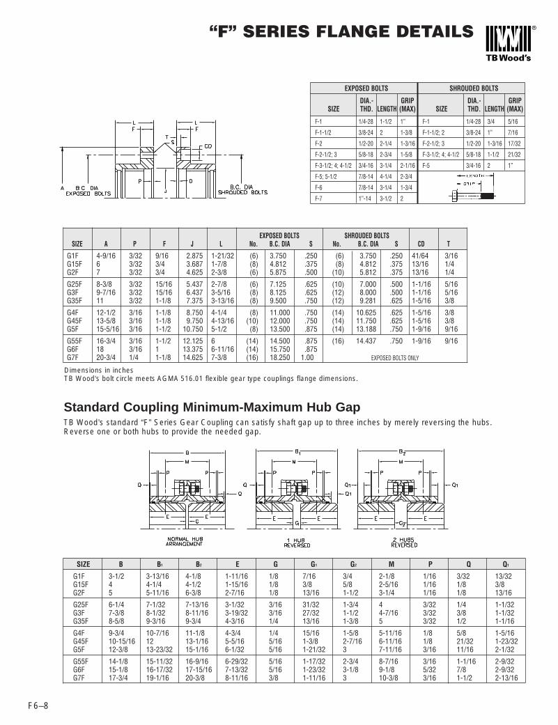
“F” SERIES FLANGE DETAILS
F6–8
EXPOSED BOLTS SHROUDED BOLTSSIZE A P F J L No. B.C. DIA S No. B.C. DIA S CD T
G1F 4-9/16 3/32 9/16 2.875 1-21/32 (6) 3.750 .250 (6) 3.750 .250 41/64 3/16G15F 6 3/32 3/4 3.687 1-7/8 (8) 4.812 .375 (8) 4.812 .375 13/16 1/4G2F 7 3/32 3/4 4.625 2-3/8 (6) 5.875 .500 (10) 5.812 .375 13/16 1/4
G25F 8-3/8 3/32 15/16 5.437 2-7/8 (6) 7.125 .625 (10) 7.000 .500 1-1/16 5/16G3F 9-7/16 3/32 15/16 6.437 3-5/16 (8) 8.125 .625 (12) 8.000 .500 1-1/16 5/16G35F 11 3/32 1-1/8 7.375 3-13/16 (8) 9.500 .750 (12) 9.281 .625 1-5/16 3/8
G4F 12-1/2 3/16 1-1/8 8.750 4-1/4 (8) 11.000 .750 (14) 10.625 .625 1-5/16 3/8G45F 13-5/8 3/16 1-1/8 9.750 4-13/16 (10) 12.000 .750 (14) 11.750 .625 1-5/16 3/8G5F 15-5/16 3/16 1-1/2 10.750 5-1/2 (8) 13.500 .875 (14) 13.188 .750 1-9/16 9/16
G55F 16-3/4 3/16 1-1/2 12.125 6 (14) 14.500 .875 (16) 14.437 .750 1-9/16 9/16G6F 18 3/16 1 13.375 6-11/16 (14) 15.750 .875G7F 20-3/4 1/4 1-1/8 14.625 7-3/8 (16) 18.250 1.00
EXPOSED BOLTS
DIA.- GRIPSIZE THD. LENGTH (MAX)
F-1 1/4-28 1-1/2 1”
F-1-1/2 3/8-24 2 1-3/8
F-2 1/2-20 2-1/4 1-3/16
F-2-1/2; 3 5/8-18 2-3/4 1-5/8
F-3-1/2; 4; 4-1/2 3/4-16 3-1/4 2-1/16
F-5; 5-1/2 7/8-14 4-1/4 2-3/4
F-6 7/8-14 3-1/4 1-3/4
F-7 1”-14 3-1/2 2
SHROUDED BOLTS
DIA.- GRIPSIZE THD. LENGTH (MAX)
F-1 1/4-28 3/4 5/16
F-1-1/2; 2 3/8-24 1” 7/16
F-2-1/2; 3 1/2-20 1-3/16 17/32
F-3-1/2; 4; 4-1/2 5/8-18 1-1/2 21/32
F-5 3/4-16 2 1”
Standard Coupling Minimum-Maximum Hub GapTB Wood’s standard “F” Series Gear Coupling can satisfy shaft gap up to three inches by merely reversing the hubs.Reverse one or both hubs to provide the needed gap.
SIZE B B1 B2 E G G1 G2 M P Q Q1
G1F 3-1/2 3-13/16 4-1/8 1-11/16 1/8 7/16 3/4 2-1/8 1/16 3/32 13/32G15F 4 4-1/4 4-1/2 1-15/16 1/8 3/8 5/8 2-5/16 1/16 1/8 3/8G2F 5 5-11/16 6-3/8 2-7/16 1/8 13/16 1-1/2 3-1/4 1/16 1/8 13/16
G25F 6-1/4 7-1/32 7-13/16 3-1/32 3/16 31/32 1-3/4 4 3/32 1/4 1-1/32G3F 7-3/8 8-1/32 8-11/16 3-19/32 3/16 27/32 1-1/2 4-7/16 3/32 3/8 1-1/32G35F 8-5/8 9-3/16 9-3/4 4-3/16 1/4 13/16 1-3/8 5 3/32 1/2 1-1/16
G4F 9-3/4 10-7/16 11-1/8 4-3/4 1/4 15/16 1-5/8 5-11/16 1/8 5/8 1-5/16G45F 10-15/16 12 13-1/16 5-5/16 5/16 1-3/8 2-7/16 6-11/16 1/8 21/32 1-23/32G5F 12-3/8 13-23/32 15-1/16 6-1/32 5/16 1-21/32 3 7-11/16 3/16 11/16 2-1/32
G55F 14-1/8 15-11/32 16-9/16 6-29/32 5/16 1-17/32 2-3/4 8-7/16 3/16 1-1/16 2-9/32G6F 15-1/8 16-17/32 17-15/16 7-13/32 5/16 1-23/32 3-1/8 9-1/8 5/32 7/8 2-9/32G7F 17-3/4 19-1/16 20-3/8 8-11/16 3/8 1-11/16 3 10-3/8 3/16 1-1/2 2-13/16
Dimensions in inchesTB Wood’s bolt circle meets AGMA 516.01 flexible gear type couplings flange dimensions.
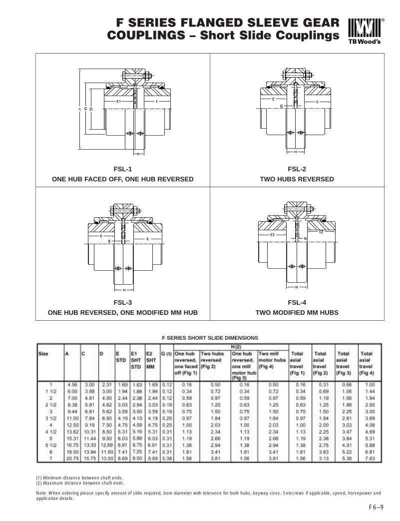
F SERIES FLANGED SLEEVE GEARCOUPLINGS – Short Slide Couplings
FSL-1
ONE HUB FACED OFF, ONE HUB REVERSED
FSL-3
ONE HUB REVERSED, ONE MODIFIED MM HUB
FSL-2
TWO HUBS REVERSED
FSL-4
TWO MODIFIED MM HUBS
F6–9
F SERIES SHORT SLIDE DIMENSIONS
(1) Minimum distance between shaft ends.(2) Maximum distance between shaft ends.
Note: When ordering please specify amount of slide required, bore diameter with tolerance for both hubs, keyway sizes. Setscrews if applicable, speed, horsepower andapplication details.

F SERIES FLANGED SLEEVE GEAR COUPLINGS– Mill Motor Type
F6–10
• Exposed bolt design isstandard on all sizes.
• Puller holes are optional.
• Shrouded bolt design isavailable on size 1 through 5when specified.
• Shrouded bolt style; hardwareis recessed in counter boredholes.
Size FMM
AISE Frame Number
A B B1 C D E E1 E2 F G G1 J KEYWAY WIDTH
KEYWAY HEIGHT
MAX BORE STD HALF
HP/100 RPM TORQUE
MAXIMUM RPM UNBALANCED
MAX PARALLEL MISALIGNMENT
602 / 802 6.0000 3.00 1.7485/1.7495 1.062 0.125 0.500 0.2501-1/2 603 / 803 6.00 6.563 6.5625 3.88 3.00 1.94 4.50 3.50 1.998/1.999 0.13 1.125 0.125 0.500 0.250 2.13 30 18900 5500 0.060
604 / 804 6.5625 3.50 1.998/1.999 1.125 0.125 0.500 0.250603 / 803 7.1667 3.50 1.998/1.999 1.125 0.250 0.500 0.250
2 604 / 804 7.00 8.063 7.1667 4.81 4.00 2.44 5.50 3.50 1.998/1.999 0.13 1.125 0.250 0.500 0.250 2.75 50 31500 5000 0.085606 / 806 7.6875 4.00 2.498/2.499 1.25 0.125 0.500 0.250603 / 803 7.7188 3.50 1.998/1.999 1.188 0.530 0.500 0.250
2-1/2 604 / 804 8.38 9.719 7.7188 5.81 4.62 3.03 6.50 3.50 1.998/1.999 0.19 1.188 0.530 0.500 0.250 3.25 90 56700 4400 0.105606 / 806 8.3438 4.00 2.498/2.499 1.313 0.410 0.500 0.250608 / 808 8.9688 4.50 2.998/2.999 1.438 0.285 0.750 0.250606 / 806 8.9063 4.00 2.498/2.499 1.313 0.560 0.500 0.250
3 608 / 808 9.44 10.781 9.5313 6.81 5.62 3.59 7.00 4.50 2.998/2.999 0.19 1.438 0.440 0.750 0.250 4.00 150 94500 4000 0.115610 / 810 9.6563 4.50 3.248/3.249 1.563 0.310 0.750 0.250612 / 812 10.2813 5.00 3.623/3.624 1.688 0.190 0.750 0.250608 / 808 10.1875 4.50 2.998/2.999 1.500 0.630 0.750 0.250
3-1/2 610 / 810 11.00 11.938 10.3125 7.84 6.50 4.19 7.50 4.50 3.248/3.249 0.25 1.625 0.500 0.750 0.250 4.62 240 151300 3500 0.130612 / 812 10.9375 5.00 3.623/3.624 1.750 0.380 0.750 0.375614 / 814 11.0625 5.00 4.2470/4.2485 1.875 0.250 1.000 0.375610 / 810 10.8750 4.50 3.248/3.249 1.625 0.780 0.750 0.250612 / 812 11.5000 5.00 3.623/3.624 1.750 0.660 0.750 0.375
4 614 / 814 12.50 13.250 11.6250 9.19 7.50 4.75 8.25 5.00 4.2470/4.2485 0.25 1.875 0.530 1.000 0.375 5.50 350 220600 3000 0.150616 / 816 12.2500 5.50 4.6220/4.6235 2.000 0.410 1.250 0.375618 / 818 12.3125 6.00 4.9970/4.9985 1.563 0.840 1.250 0.500614 / 814 12.2500 5.00 4.2470/4.2485 1.938 0.910 1.000 0.375
4-1/2 616 / 816 13.62 14.625 12.8750 10.31 8.50 5.31 9.00 5.50 4.6220/4.6235 0.31 2.063 0.780 1.250 0.375 6.00 480 302500 2700 0.175618 / 818 12.9375 6.00 4.9970/4.9985 1.625 1.220 1.250 0.500614 / 814 12.9700 5.00 4.2470/4.2485 1.938 1.310 1.000 0.375
5 616 / 816 15.31 15.844 13.5900 11.44 9.50 6.03 9.50 5.50 4.6220/4.6235 0.31 2.063 1.190 1.250 0.375 6.88 690 434900 2500 0.200618 / 818 13.6563 6.00 4.9970/4.9985 1.625 1.630 1.250 0.500
620 14.8438 6.75 5.8720/5.8735 2.063 1.190 1.500 0.750616 / 816 14.4688 5.50 4.6220/4.6235 2.063 1.440 1.250 0.375
5-1/2 618 / 818 16.75 17.719 14.5313 12.69 10.50 6.91 10.50 6.00 4.9970/4.9985 0.31 1.625 1.880 1.250 0.500 7.75 910 573500 2200 0.220620 15.7188 6.75 5.8720/5.8735 2.063 1.440 1.500 0.750622 16.8438 7.25 6.2470/6.2485 2.688 0.810 1.500 0.750
616 / 816 14.9688 5.50 4.6220/4.6235 2.063 1.470 1.250 0.3756 618 / 818 18.00 18.969 15.0313 13.94 11.50 7.41 11.25 6.00 4.9970/4.9985 0.31 1.625 1.910 1.250 0.500 8.65 1190 750000 2100 0.120
620 16.2188 6.75 5.8720/5.8735 2.063 1.470 1.500 0.750622 17.3438 7.25 6.2470/6.2485 2.688 0.840 1.500 0.750
*ALL KEYWAYS SHOWN ARE PARALLEL TO THE TAPER. TAPER IS 1-1/4” INCH PER FOOT ON DIAMETER.
SPECIFYING TAPERED BORESPlease provide the following information for taper bore hubs:1) Drawing of HUB showing bore and keyway details.
OR2) Drawing of shaft showing:
(LD) Large diameter, specify with tolerance.(S) Length of taper, measure parallel to shaft centerline.(T) Taper angle. Specify as degrees, taper per foot or a percentage.(P) Desired pull-up of hub on shaft.(D) Counterbore diameter as required.(Y) Counterbore depth as required.Keyway or shaft keyseat dimensions. Specify width, depth and keyway taper angle.

Item (Qty) Part Number DescriptionFlex Hubs (2) G4FRB 4F Rough Bore Flex Hubs
G4FSEB or 4F Sleeve with Exposed BoltsSleeves (2) G4FSSB 4F Sleeve with Shrouded Bolts
G4AEB or Hardware and Gasket for 4F with Exposed BoltsAccessory Kit (1) G4ASB Hardware and Gasket for 4F with Shrouded Bolts
Plate (1) G4LEF 4F LEF Plate
FLEXIBLE HUBS
CONSULTFACTORY
F SERIES FLANGED SLEEVE GEARCOUPLINGS – Limited End Float Type
F6–11
• Exposed bolt design is standard onall sizes.
• Puller holes are optional.
• Shrouded bolt design is available onsize 1 through 5 when specified.
• Shrouded bolt style; hardware isrecessed in counter bored holes.
Notes:(1) “H” Dimension – Clearance to align coupling.(2) AGMA CLASS 8 balance requires the manufacture
of two special flexible hubs.(3) When ordering please specify bore diameter with
tolerances for both hubs, keyway sizes, set screws ifapplicable, speed, horsepower, application details,amount of thrust on either or both shafts, andamount of end float desired.
(4) Horsepower, Torque Capacity and ParallelMisalignment Capacity for sizes 1 through 5-1/2 arebased on 1-1/2 degrees angular misalignment pergear mesh and maximum bore. Sizes 6 & 7 arebased on 3/4 degree angular misalignment. ConsultEngineering for greater HP capacity.
(5) Dimension is total end float. (May be modified to suitcustomer requirements.)
1 4.56 3.56 3.00 2.31 1.69 0.19 0.13 .031 4.19 0.13 0.06 91 1/2 6.00 4.06 3.88 3.00 1.94 0.19 0.13 .031 4.75 0.13 0.06 19
2 7.00 5.06 4.81 4.00 2.44 0.19 0.13 .031 6.00 0.13 0.09 342 1/2 8.38 6.34 5.81 4.62 3.03 0.28 0.19 .047 7.12 0.19 0.11 54
3 9.44 7.47 6.81 5.62 3.59 0.28 0.19 .047 8.12 0.19 0.12 803 1/2 11.00 8.69 7.84 6.50 4.19 0.31 0.19 .063 9.38 0.25 0.13 130
4 12.50 9.91 9.19 7.50 4.75 0.41 0.31 .047 10.25 0.19 0.15 1904 1/2 13.62 11.13 10.31 8.50 5.31 0.50 0.38 .063 11.50 0.25 0.18 250
5 15.31 12.59 11.44 9.50 6.03 0.53 0.38 .078 13.00 0.31 0.20 3805 1/2 16.75 14.34 12.69 10.50 6.91 0.53 0.38 .078 14.38 0.31 0.22 520
6 18.00 15.31 13.94 11.50 7.41 0.50 0.38 .063 17.00 0.25 0.12 6507 20.75 18.00 15.75 13.00 8.69 0.63 0.50 .063 20.00 0.25 0.14 950
STANDARD DIMENSIONS (3)
RATINGS (4)
Size A B C D E G G1 G2 H(1) LEF (5)Parallel
MisalignmentCapacity (4)
Approx.Wt. (Lbs.)
SolidBore
1 12 7563 0.44 1.62 1.75 6000 95001 1/2 30 18900 0.44 2.13 2.25 5500 8500
2 50 31500 0.56 2.75 3.00 5000 78002 1/2 90 56700 0.81 3.25 3.38 4400 6800
3 150 94500 1.19 4.00 4.25 4000 62003 1/2 240 151300 1.56 4.62 4.88 3500 5500
4 350 220600 1.81 5.50 5.62 3000 46004 1/2 480 302500 1.81 6.00 6.44 2700 4100
5 690 434900 2.31 6.88 7.00 2500 39005 1/2 910 57350 3.06 7.75 7.88 2200
6 1190 75000 4.06 8.63 8.75 21007 1600 1008400 4.56 9.50 9.75 2000
SIZE HP @ TORQUE MIN MAX BORERPM in. lbs. BORE STD KEY
MAX BORESHALLOW
KEY
MAX RPM UNBALANCED
MAX RPMBALANCED
AGMACLASS 8 (2)
Below is an ordering example of a 4FLEF Coupling.

F SERIES FLANGED SLEEVE GEAR COUPLINGS – Vertical Type
F6–12
• Vertical couplings require avertical plate and a button.Standard flex hubs are facedoff (shorten) per the “E”dimension.
• Contact factory for price andavailability.
• Exposed bolt design isstandard on all sizes.
• Puller holes are optional.
• Shrouded bolt design isavailable on size 1 through 5when specified.
• Shrouded bolt style; hardwareis recessed in counter boredholes.
Notes:
(1) When ordering please specify bore diameter with tolerances for both hubs, keyway sizes, set screws if applicable, speed, horsepower, and application details.
(2) Horsepower, Torque capacity, and parallel misalignment capacity for sizes 1 through 5-1/2 are based on 1-1/2 degrees angular misalignment per gear mesh andmaximum bore. Sizes 6 through 9 are based on 3/4 degree angular misalignment. Consult engineering for greater HP capacity.
(3) “H” Dimension – Clearance to align coupling.
(4) AGMA class 8 balance requires the manufacture of two special flexible hubs. Many configurations of “F” Series couplings are available to fit your unique application.Consult Wood’s mechanical application engineers for design.

STOCK SPACERSFor Use With F, MXB, or K100 Series Couplings
F6–13
Coupling Size
DBSESpacer Part
NumberSPOOL
LENGTH
F Series "B"
Dimension
MXB Series "B"
Dimension
K Series "B"
Dimension
MAX RPM
Approx. Spacer weight
1 1/2 4 3/8 G15EBX438 4.25 8.154 8.394 8.37 5500 9.81 1/2 5 G15EBX5 4.88 8.784 9.024 9 5500 10.7
2 4 3/8 G2EBX438 4.25 9.154 9.37 9.37 5000 13.42 5 G2EBX5 4.88 9.784 10 10 5000 14.12 7 G2EBX7 6.88 11.784 12 12 5000 16.6
2 1/2 5 G25EBX5 4.81 11.25 11.25 11.25 4400 242 1/2 7 G25EBX7 6.81 13.25 13.25 13.25 4400 27
3 5 G3EBX5 4.81 12.37 12.37 12.37 4000 293 7 G3EBX7 6.81 14.37 14.37 14.37 4000 33
3 1/2 5 G35EBX5 4.75 13.63 13.63 13.63 3500 453 1/2 7 G35EBX7 6.75 15.63 15.63 15.63 3500 51
Below is an ordering example of a 2 FSP CouplingItem (Qty) Part Number DescriptionFlex Hub (2) G2FRB 2 F Rough Bore Flex HubSleeve (2) G2FSEB 2 F Sleeve with Exposed BoltsSpacer (1) G2EBX5 2 X 5" DBSE Spacer with Exposed BoltsAccessory Kit (2) G2AEB Hardware and Gasket for 2 F with Exposed Bolts
“F” or “MXB” Spacer Type Coupling
“K 100” Series Spacer Type Coupling
Other Sizes, DBSE’s, and shrouded bolt patterns are Available as Specials.
C Series Spacer couplings are also available, consult factory.
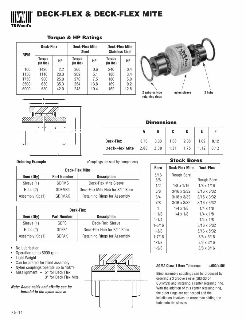
DECK-FLEX & DECK-FLEX MITE
F6–14
A B C D E F
Deck-Flex 3.75 3.38 1.88 2.38 1.62 0.12
Deck-Flex Mite 2.88 2.38 1.31 1.75 1.12 0.12
Deck-Flex Deck-Flex Mite Deck-Flex Mite
RPMSteel Stainless Steel
Torque Torque Torque(in lbs) HP (in lbs) HP (in lbs) HP
100 1420 2.2 360 0.6 240 0.41150 1110 20.3 282 5.1 188 3.41750 900 25.0 270 7.5 180 5.03500 630 35.3 254 13.8 169 9.25000 530 42.0 243 19.4 162 12.8
Bore Deck-Flex Mite Deck-Flex
5/16 Rough Bore3/8 . . . Rough Bore1/2 1/8 x 1/16 1/8 x 1/165/8 3/16 x 3/32 3/16 x 3/323/4 3/16 x 3/32 3/16 x 3/327/8 3/16 x 3/32 3/16 x 3/321 1/4 x 1/8 1/4 x 1/8
1-1/8 1/4 x 1/8 1/4 x 1/81-1/4 1/4 x 1/81-5/16 5/16 x 5/321-3/8 5/16 x 5/321-7/16 3/8 x 3/161-1/2 3/8 x 3/161-5/8 3/8 x 3/16
Deck-Flex Mite
Item (Qty) Part Number Description
Sleeve (1) GDFMS Deck-Flex Mite Sleeve
Hubs (2) GDFM34 Deck-Flex Mite Hub for 3/4” Bore
Assembly Kit (1) GDFMAK Retaining Rings for Assembly
Torque & HP Ratings
Dimensions
Stock BoresOrdering Example (Couplings are sold by component)
Deck-Flex
Item (Qty) Part Number Description
Sleeve (1) GDFS Deck-Flex Sleeve
Hubs (2) GDF34 Deck-Flex Hub for 3/4” Bore
Assembly Kit (1) GDFAK Retaining Rings for Assembly
• No Lubrication• Operation up to 5000 rpm• Light Weight• Can be altered for blind assembly• Nylon couplings operate up to 150°F• Misalignment – 5° for Deck Flex
3° for Deck Flex Mite
Note: Some acids and alkalis can be harmful to the nylon sleeve.
AGMA Class 1 Bore Tolerance +.000/+.001
Blind assembly couplings can be produced byordering a 3 groove sleeve (GDFS3 orGDFMS3) and installing a center retaining ring.With the addition of this center retaining ring,the outer rings are not needed and theinstallation involves no more than sliding thehubs into the sleeves.
2 spirolox type nylon sleeve 2 hubsretaining rings


![rweb Factory] r Web Factory] (IOT: Internet of …rweb Factory] r Web Factory] (IOT: Internet of Things) UN TfiÔÍcbU) Online Service ,o.ip TEL 03-3462-1181 FAX 03-3462-1185 ...](https://static.documents.pub/doc/80x56/5f925f05a6a116043f68f587/rweb-factory-r-web-factory-iot-internet-of-rweb-factory-r-web-factory-iot.jpg)


