30
875r 4-Cycle Gas Trimmer OPERATOR’S MANUAL FOR QUESTIONS, CALL 1-800-345-8746 in U.S. or 1-800-265-6778 in CANADA www.ryobi.com IMPORTANT MANUAL DO NOT THROW AWA Y
| Date post: | 07-Apr-2018 |
| Category: |
Documents |
| Upload: | spectregadget |
| View: | 222 times |
| Download: | 0 times |

8/4/2019 Ryobi 875R 4-Cycle Straight Shaft Trimmer Plus Manual
http://slidepdf.com/reader/full/ryobi-875r-4-cycle-straight-shaft-trimmer-plus-manual 1/30
875r 4-Cycle Gas Trimmer
OPERATOR’S MANUAL
FOR QUESTIONS, CALL 1-800-345-8746 in U.S. or1-800-265-6778 in CANADA
www.ryobi.com
IMPORTANT MANUAL DO NOT THROW AWA
8/4/2019 Ryobi 875R 4-Cycle Straight Shaft Trimmer Plus Manual
http://slidepdf.com/reader/full/ryobi-875r-4-cycle-straight-shaft-trimmer-plus-manual 2/30
THANK YOU
Thank you for buying this quality product. This modernoutdoor power tool will provide many hours of usefulservice. You will find it to be a great labor-saving device.This operator’s manual provides you with easy-to-understand operating instructions. Read the wholemanual and follow all the instructions to keep your new
outdoor power tool in top operating condition. The othermanual that came with your power tool, the partsmanual, contains all the information that you need toorder parts.
PRODUCT REFERENCES, ILLUSTRATIONS ANDSPECIFICATIONS
All information, illustrations and specifications in thismanual are based on the latest product informationavailable at the time of printing. We reserve the right tomake changes at any time without notice.
Copyright© 1998 Ryobi Outdoor Products, Inc. All Rights Reserved.
Click-Link® is a registered trademark of Ryobi Outdoor
Products.SpeedSpool® is a registered trademark of RyobiOutdoor Products.
SERVICE INFORMATION
Service on this unit both within and after the warrantyperiod should be performed only by an authorized andapproved service dealer.Dial:
• 1-800-345-8746 or www.ryobi.com on the world wideweb for authorized service dealers in the United States
Or
• 1-800-265-6778 in Canada to obtain the listing of theauthorized service dealer nearest you.
to obtain the listing of the authorized service dealernearest you.
DO NOT RETURN THE UNIT TO THE RETAILER.
NOTE: PROOF OF PURCHASE WILL BE REQUIREDFOR WARRANTY SERVICE.
Make sure this manual is carefully read and understoodbefore starting or operating this equipment.
THIS PRODUCT IS COVERED BY ONE OR MOREUS PATENTS, OTHER PATENTS PENDING.
2
INTRODUCTION TABLE OF CONTENTS
I. California Emission Regulations . . . . . . . . . . . . . . . . .
II. Rules for Safe Operation . . . . . . . . . . . . . . . . . . . . . 4 A. Important Safety Information . . . . . . . . . . . . . . . 4B. Safety and International Symbols . . . . . . . . . . . 6C. Know Your Unit . . . . . . . . . . . . . . . . . . . . . . . . . . .
III. Assembly Instructions . . . . . . . . . . . . . . . . . . . . . . . .
A. Adjusting the J handle . . . . . . . . . . . . . . . . . . . . . .
IV. Oil and Fuel Information . . . . . . . . . . . . . . . . . . . 10-1 A. Recommended Oil Type . . . . . . . . . . . . . . . . . . . 1B. Adding Oil to Crankcase-Initial Use . . . . . . . . . . . 1C. Recommended Fuel Type . . . . . . . . . . . . . . . . . . 1D. Fueling the Unit . . . . . . . . . . . . . . . . . . . . . . . . . . 1
V. Starting/Stopping Instructions . . . . . . . . . . . . . . . . . 1
VI. Operating Instructions . . . . . . . . . . . . . . . . . . . . 13-1 A. Operating the Click-Link System . . . . . . . . . . . . . 1B. Holding the Trimmer . . . . . . . . . . . . . . . . . . . . . . 1C. Adjusting Trimming Line Length . . . . . . . . . . . . . 1D. Tips for Best Trimming Results . . . . . . . . . . . . . . 1E. Decorative Trimming . . . . . . . . . . . . . . . . . . . . . . 1
VII. Maintenance and Repair Instructions . . . . . . . . . 15-2 A. Maintenance Schedule . . . . . . . . . . . . . . . . . . . . 1B. Line Installation for the SpeedSpool . . . . . . . . . . 1C. Installing a Prewound Reel . . . . . . . . . . . . . . . . . 1D. Cleaning the SpeedSpool . . . . . . . . . . . . . . . . . . 1E. SpeedSpool Replacement Parts . . . . . . . . . . . . . 1F. Checking the Oil Level . . . . . . . . . . . . . . . . . . . . . 1G. Changing the Oil . . . . . . . . . . . . . . . . . . . . . . . . . 1H. Air Filter Maintenance . . . . . . . . . . . . . . . . . . . . . 2I. Carburetor Adjustment . . . . . . . . . . . . . . . . . . . . 2J. Rocker Arm Clearance . . . . . . . . . . . . . . . . . . . . . 2K. Replacing the Spark Plug . . . . . . . . . . . . . . . . . . 2L. Spark Arrestor Maintenance . . . . . . . . . . . . . . . . 2M.Accessories/Replacement parts . . . . . . . . . . . . . 2
VIII.Cleaning and Storage . . . . . . . . . . . . . . . . . . . . . . . . 2
IX. Troubleshooting Chart . . . . . . . . . . . . . . . . . . . . . . . 2
X. Specifications . . . . . . . . . . . . . . . . . . . . . . . . . . . . . . 2
XI. Warranty . . . . . . . . . . . . . . . . . . . . . . . . . . . . . . . 29-3
CONTENTS OF CARTONThis carton should include of the following:
• Model 875r Trimmer with J-Handle
• Operator's Manual
• Parts Manual
• Product Registration Card
• Bottle of 4-Cycle Oil
8/4/2019 Ryobi 875R 4-Cycle Straight Shaft Trimmer Plus Manual
http://slidepdf.com/reader/full/ryobi-875r-4-cycle-straight-shaft-trimmer-plus-manual 3/30 3
CALIFORNIA EMISSION REGULATIONS
WARNING
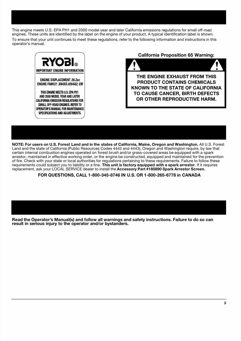
NOTE: For users on U.S. Forest Land and in the states of California, Maine, Oregon and Washington. All U.S. ForestLand and the state of California (Public Resources Codes 4442 and 4443), Oregon and Washington require, by law thatcertain internal combustion engines operated on forest brush and/or grass-covered areas be equipped with a sparkarrestor, maintained in effective working order, or the engine be constructed, equipped and maintained for the preventionof fire. Check with your state or local authorities for regulations pertaining to these requirements. Failure to follow theserequirements could subject you to liability or a fine. This unit is factory equipped with a spark arrestor. If it requiresreplacement, ask your LOCAL SERVICE dealer to install the Accessory Part #180890 Spark Arrestor Screen.
FOR QUESTIONS, CALL 1-800-345-8746 IN U.S. OR 1-800-265-6778 in CANADA
California Proposition 65 Warning:
THE ENGINE EXHAUST FROM THIS
PRODUCT CONTAINS CHEMICALS
KNOWN TO THE STATE OF CALIFORNIA
TO CAUSE CANCER, BIRTH DEFECTS
OR OTHER REPRODUCTIVE HARM.
This engine meets U.S. EPA PH1 and 2000 model year and later California emissions regulations for small off-roadengines. These units are identified by the label on the engine of your product. A typical identification label is shown.
To ensure that your unit continues to meet these regulations, refer to the following information and instructions in thisoperator’s manual.
Read the Operator’s Manual(s) and follow all warnings and safety instructions. Failure to do so canresult in serious injury to the operator and/or bystanders.
SPARK ARRESTOR
WARNING!
8/4/2019 Ryobi 875R 4-Cycle Straight Shaft Trimmer Plus Manual
http://slidepdf.com/reader/full/ryobi-875r-4-cycle-straight-shaft-trimmer-plus-manual 4/30
RULES FOR SAFE OPERATION
4
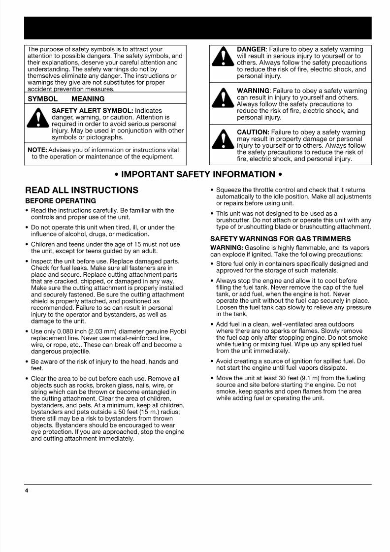
DANGER: Failure to obey a safety warningwill result in serious injury to yourself or toothers. Always follow the safety precautionsto reduce the risk of fire, electric shock, andpersonal injury.
WARNING: Failure to obey a safety warning
can result in injury to yourself and others. Always follow the safety precautions toreduce the risk of fire, electric shock, andpersonal injury.
CAUTION: Failure to obey a safety warningmay result in property damage or personalinjury to yourself or to others. Always followthe safety precautions to reduce the risk offire, electric shock, and personal injury.
The purpose of safety symbols is to attract yourattention to possible dangers. The safety symbols, andtheir explanations, deserve your careful attention andunderstanding. The safety warnings do not bythemselves eliminate any danger. The instructions orwarnings they give are not substitutes for properaccident prevention measures.
SYMBOL MEANING
SAFETY ALERT SYMBOL: Indicatesdanger, warning, or caution. Attention isrequired in order to avoid serious personalinjury. May be used in conjunction with othersymbols or pictographs.
NOTE: Advises you of information or instructions vitalto the operation or maintenance of the equipment.
• IMPORTANT SAFETY INFORMATION •
READ ALL INSTRUCTIONSBEFORE OPERATING
• Read the instructions carefully. Be familiar with thecontrols and proper use of the unit.
• Do not operate this unit when tired, ill, or under theinfluence of alcohol, drugs, or medication.
• Children and teens under the age of 15 must not usethe unit, except for teens guided by an adult.
• Inspect the unit before use. Replace damaged parts.Check for fuel leaks. Make sure all fasteners are inplace and secure. Replace cutting attachment partsthat are cracked, chipped, or damaged in any way.
Make sure the cutting attachment is properly installedand securely fastened. Be sure the cutting attachmentshield is properly attached, and positioned asrecommended. Failure to so can result in personalinjury to the operator and bystanders, as well asdamage to the unit.
• Use only 0.080 inch (2.03 mm) diameter genuine Ryobireplacement line. Never use metal-reinforced line,wire, or rope, etc.. These can break off and become adangerous projectile.
• Be aware of the risk of injury to the head, hands andfeet.
• Clear the area to be cut before each use. Remove all
objects such as rocks, broken glass, nails, wire, orstring which can be thrown or become entangled inthe cutting attachment. Clear the area of children,bystanders, and pets. At a minimum, keep all children,bystanders and pets outside a 50 feet (15 m.) radius;there still may be a risk to bystanders from thrownobjects. Bystanders should be encouraged to weareye protection. If you are approached, stop the engineand cutting attachment immediately.
• Squeeze the throttle control and check that it returnsautomatically to the idle position. Make all adjustmenor repairs before using unit.
• This unit was not designed to be used as abrushcutter. Do not attach or operate this unit with atype of brushcutting blade or brushcutting attachmen
SAFETY WARNINGS FOR GAS TRIMMERS
WARNING: Gasoline is highly flammable, and its vaporcan explode if ignited. Take the following precautions:
• Store fuel only in containers specifically designed andapproved for the storage of such materials.
• Always stop the engine and allow it to cool before
filling the fuel tank. Never remove the cap of the fueltank, or add fuel, when the engine is hot. Neveroperate the unit without the fuel cap securely in placeLoosen the fuel tank cap slowly to relieve any pressuin the tank.
• Add fuel in a clean, well-ventilated area outdoorswhere there are no sparks or flames. Slowly removethe fuel cap only after stopping engine. Do not smokwhile fueling or mixing fuel. Wipe up any spilled fuelfrom the unit immediately.
• Avoid creating a source of ignition for spilled fuel. Donot start the engine until fuel vapors dissipate.
• Move the unit at least 30 feet (9.1 m) from the fueling
source and site before starting the engine. Do notsmoke, keep sparks and open flames from the areawhile adding fuel or operating the unit.
8/4/2019 Ryobi 875R 4-Cycle Straight Shaft Trimmer Plus Manual
http://slidepdf.com/reader/full/ryobi-875r-4-cycle-straight-shaft-trimmer-plus-manual 5/30
RULES FOR SAFE OPERATION
5
• If you strike or become entangled with a foreignobject, stop the engine immediately and check fordamage. Do not operate before repairing damage. Donot operate the unit with loose or damaged parts.
• Stop and switch the engine to off for maintenance,repair, or for changing the cutting attachment or otherattachments.
• Use only genuine Ryobi replacement parts whenservicing this unit. These parts are available fromyour authorized service dealer. Do not use parts,accessories or attachments not authorized by Ryobifor this unit. Doing so could lead to serious injury tothe user, or damage to the unit, and void yourwarranty.
• Keep unit clean of vegetation and other materials.They may become lodged between the cuttingattachment and shield.
• To reduce fire hazard, replace faulty muffler and sparkarrestor, keep the engine and muffler free from grass,leaves, excessive grease or carbon build up.
OTHER SAFETY WARNINGS
• Never store the unit, with fuel in the tank, inside abuilding where fumes may reach an open flame orspark.
• Allow the engine to cool before storing or transporting.Be sure to secure the unit while transporting.
• Store the unit in a dry area, locked up or up highto prevent unauthorized use or damage, out of thereach of children.
• Never douse or squirt the unit with water or any otherliquid. Keep handles dry, clean and free from debris.
Clean after each use, see Cleaning and Storageinstructions.
• Keep these instructions. Refer to them often and usethem to instruct other users. If you loan someone thisunit, also loan them these instructions.
SAVE THESE INSTRUCTIONS
WHILE OPERATING
• Never start or run the unit inside a closed room orbuilding. Breathing exhaust fumes can kill. Operatethis unit only in a well ventilated area outdoors.
• Wear safety glasses or goggles that are marked asmeeting ANSI Z87.1-1989 standards, and ear/hearing
protection when operating this unit. Wear a face ordust mask if the operation is dusty. Long sleeve shirtsare recommended.
• Wear heavy, long pants, boots and gloves. Do notwear loose clothing, jewelry, short pants, sandals orgo barefoot. Secure hair above shoulder level.
• The cutting attachment shield must always be in placewhile operating the unit. Do not operate unit withoutboth trimming lines extended, and the proper lineinstalled. Do not extend the trimming line beyond thelength of the shield.
• This unit has a clutch. The cutting attachment remainsstationary when the engine is idling. If it does not, have
the unit adjusted by an authorized service technician.• Adjust the J-Handle to your size to provide the best
grip.
• Be sure the cutting attachment is not in contact withanything before starting the unit.
• Use the unit only in daylight or good artificial light.
• Avoid accidental starting. Be in the starting positionwhenever pulling the starter rope. The operator andunit must be in a stable position while starting. SeeStarting/Stopping Instructions.
• Use the right tool. Only use this tool for the purposeintended.
• Do not overreach. Always keep proper footing andbalance.
• Always hold the unit with both hands when operating.Keep a firm grip on both the front and rear handle orgrips.
• Keep hands, face, and feet at a distance from allmoving parts. Do not touch or try to stop the cuttingattachment when it is rotating.
• Do not touch the engine or muffler. These parts getextremely hot from operation. When turned off theyremain hot for a short time.
• Do not operate the engine faster than the speedneeded to cut, trim or edge. Do not run the engine athigh speed when not cutting.
• Always stop the engine when cutting is delayed orwhen walking from one cutting location to another.

8/4/2019 Ryobi 875R 4-Cycle Straight Shaft Trimmer Plus Manual
http://slidepdf.com/reader/full/ryobi-875r-4-cycle-straight-shaft-trimmer-plus-manual 6/30
RULES FOR SAFE OPERATION
6
SAFETY AND INTERNATIONAL SYMBOLS
This operator's manual describes safety and international symbols and pictographs that may appear on this product.Read the operator's manual for complete safety, assembly, operating and maintenance and repair information.
SYMBOL MEANING
• SAFETY ALERT SYMBOLIndicates danger, warning, or caution. May be used in conjunction with othersymbols or pictographs.
• WARNING - READ OPERATOR'S MANUAL
Read the Operator’s Manual(s) and follow all warnings and safety instructions.Failure to do so can result in serious injury to the operator and/or bystanders.
• FOR SERVICE INFORMATION, CALL:
USA: 1-800-345-8746
CANADA: 1-800-265-6778
• WEAR EYE AND HEARING PROTECTION
WARNING: Thrown objects and loud noise can cause severe eye injury and hearing loss.Wear eye protection meeting ANSI Z87.1-1989 standards and ear protection whenoperating this unit.
• KEEP BYSTANDERS AWAY
WARNING: Keep all bystanders, especially children and pets, at least 50 feet (15 m.)from the operating area.
• PRIMER BULB
Push primer bulb, fully and slowly, 5 to 7 times.
• UNLEADED FUEL
Always use clean, fresh unleaded fuel.
• OILRefer to operator's manual for the proper type of oil.

8/4/2019 Ryobi 875R 4-Cycle Straight Shaft Trimmer Plus Manual
http://slidepdf.com/reader/full/ryobi-875r-4-cycle-straight-shaft-trimmer-plus-manual 7/30
RULES FOR SAFE OPERATION
7
SYMBOL MEANING
• THROWN OBJECTS AND ROTATING CUTTER CAN CAUSE SEVERE INJURY
WARNING: Do not operate without the cutting attachment shield in place.Keep away from the rotating cutting attachment.
• ON/OFF STOP CONTROL
ON / START / RUN
• ON/OFF STOP CONTROL
OFF OR STOP
• HOT SURFACE WARNING
Do not touch a hot muffler or cylinder. You may get burned. These parts get extremely hot
from operation. When turned off they remain hot for a short time.
• SHARP BLADE
WARNING: Sharp blade on cutting attachment shield. To prevent serious injury, do nottouch line cutting blade.
• CHOKE CONTROL
A • FULL choke position.B • PARTIAL choke position.C • RUN position.
WARNING: The operation of any power tool can cause foreign objects to be thrown into youreyes. This can lead to severe eye damage. Before commencing power tool operation, alwayswear safety glasses or goggles that are marked as meeting ANSI Z87.1-1989 standards, anda full face shield when needed.
8/4/2019 Ryobi 875R 4-Cycle Straight Shaft Trimmer Plus Manual
http://slidepdf.com/reader/full/ryobi-875r-4-cycle-straight-shaft-trimmer-plus-manual 8/30
RULES FOR SAFE OPERATION
8
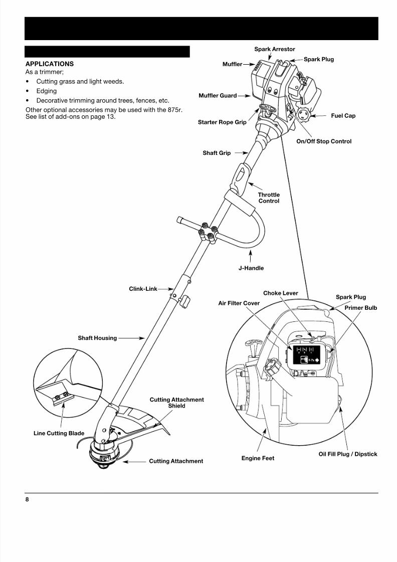
APPLICATIONS
As a trimmer;
• Cutting grass and light weeds.
• Edging
• Decorative trimming around trees, fences, etc.
Other optional accessories may be used with the 875r.See list of add-ons on page 13.
Cutting AttachmentShield
Fuel Cap
ThrottleControl
J-Handle
Cutting Attachment
Shaft Grip
Primer Bu
Choke Lever
Oil Fill Plug / Dipsti
Air Filter Cover
Engine Feet
Spark Plug
On/Off Stop Control
Shaft Housing
Starter Rope Grip
KNOW YOUR UNIT
Clink-Link
Line Cutting Blade
Spark PlugMuffler
Muffler Guard
Spark Arrestor
8/4/2019 Ryobi 875R 4-Cycle Straight Shaft Trimmer Plus Manual
http://slidepdf.com/reader/full/ryobi-875r-4-cycle-straight-shaft-trimmer-plus-manual 9/30
ASSEMBLY INSTRUCTIONS
9
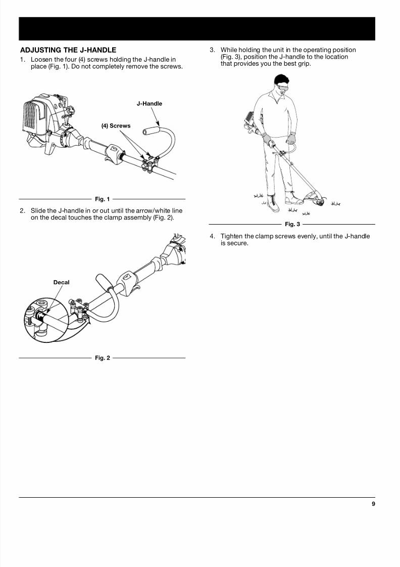
4. Tighten the clamp screws evenly, until the J-handleis secure.
3. While holding the unit in the operating position(Fig. 3), position the J-handle to the locationthat provides you the best grip.
Decal
ADJUSTING THE J-HANDLE
1. Loosen the four (4) screws holding the J-handle inplace (Fig. 1). Do not completely remove the screws.
(4) Screws
J-Handle
2. Slide the J-handle in or out until the arrow/white lineon the decal touches the clamp assembly (Fig. 2).
Fig. 1
Fig. 2
Fig. 3

8/4/2019 Ryobi 875R 4-Cycle Straight Shaft Trimmer Plus Manual
http://slidepdf.com/reader/full/ryobi-875r-4-cycle-straight-shaft-trimmer-plus-manual 10/30
OIL AND FUEL INFORMATION
10
RECOMMENDED OIL TYPE
Using the proper type and weight of oil in thecrankcase is extremely important. Check theoil before each use and change the oilregularly. Failure to use the correct oil, or
using dirty oil, can cause premature engine wear andfailure.
Use a high-quality SAE 30 weight oil of API (AmericanPetroleum Institute) service class SF, SG, SH.
ADDING OIL TO CRANKCASE – INITIAL USE
NOTE: This unit is shipped without being filled with oil.In order to avoid damage to the unit, put oil inthe crankcase before attempting to start unit.
Your unit is supplied with one 3.4 fluid oz. (100 ml.)bottle of SAE 30 SF, SG, SH oil (Fig. 4).
NOTE: Save the bottle to measure the correct amountfor future oil changes. See Changing the OilPg. 19.
1. Unscrew the top of the bottle of oil and remove the
paper seal covering the opening. Replace top. Cutthe tip off the funnel spout (Fig. 4).
2. Place the unit on a flat level surface.
3. Remove the oil plug / dipstick from the crankcase(Fig. 5).
Fig. 4
Fig. 6
Oil Fill
NOTE: Never add oil to the fuel or fuel tank.
5. Wipe up any oil that may have spilled and reinstall
the oil fill plug / dipstick.The importance of checking and maintaining the propeoil level in the crankcase cannot be overemphasized.Check oil before each use and change as needed. SeeChanging the Oil Pg. 19.
Oil Fill Plug/Dipstick
Oil Fill Hole
Fig. 5
4. Pour the entire bottle of oil into the oil fill hole(Fig. 6).
O-Ring
Funnel Spout
8/4/2019 Ryobi 875R 4-Cycle Straight Shaft Trimmer Plus Manual
http://slidepdf.com/reader/full/ryobi-875r-4-cycle-straight-shaft-trimmer-plus-manual 11/30
OIL AND FUEL INFORMATION
11
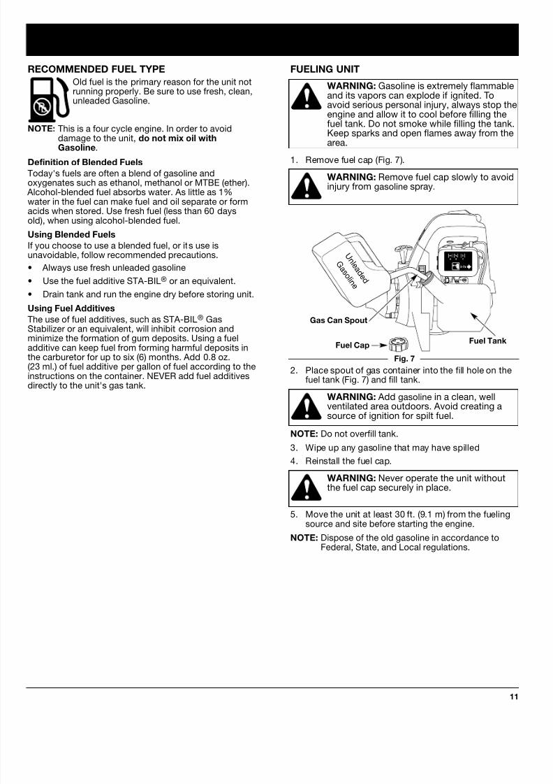
FUELING UNIT
WARNING: Gasoline is extremely flammableand its vapors can explode if ignited. Toavoid serious personal injury, always stop theengine and allow it to cool before filling thefuel tank. Do not smoke while filling the tank.
Keep sparks and open flames away from thearea.
1. Remove fuel cap (Fig. 7).
WARNING: Remove fuel cap slowly to avoidinjury from gasoline spray.
Fig. 7
Fuel CapFuel Tank
Gas Can Spout
2. Place spout of gas container into the fill hole on thefuel tank (Fig. 7) and fill tank.
WARNING: Add gasoline in a clean, wellventilated area outdoors. Avoid creating asource of ignition for spilt fuel.
NOTE: Do not overfill tank.
3. Wipe up any gasoline that may have spilled
4. Reinstall the fuel cap.
WARNING: Never operate the unit withoutthe fuel cap securely in place.
5. Move the unit at least 30 ft. (9.1 m) from the fuelingsource and site before starting the engine.
NOTE: Dispose of the old gasoline in accordance to
Federal, State, and Local regulations.
RECOMMENDED FUEL TYPE
Old fuel is the primary reason for the unit notrunning properly. Be sure to use fresh, clean,unleaded Gasoline.
NOTE: This is a four cycle engine. In order to avoid
damage to the unit, do not mix oil withGasoline.
Definition of Blended Fuels
Today's fuels are often a blend of gasoline andoxygenates such as ethanol, methanol or MTBE (ether).
Alcohol-blended fuel absorbs water. As little as 1%water in the fuel can make fuel and oil separate or formacids when stored. Use fresh fuel (less than 60 daysold), when using alcohol-blended fuel.
Using Blended Fuels
If you choose to use a blended fuel, or its use isunavoidable, follow recommended precautions.
• Always use fresh unleaded gasoline
• Use the fuel additive STA-BIL® or an equivalent.
• Drain tank and run the engine dry before storing unit.
Using Fuel Additives
The use of fuel additives, such as STA-BIL® GasStabilizer or an equivalent, will inhibit corrosion andminimize the formation of gum deposits. Using a fueladditive can keep fuel from forming harmful deposits inthe carburetor for up to six (6) months. Add 0.8 oz.(23 ml.) of fuel additive per gallon of fuel according to theinstructions on the container. NEVER add fuel additivesdirectly to the unit's gas tank.
U n l e a
d e d
G a s o l i n e

8/4/2019 Ryobi 875R 4-Cycle Straight Shaft Trimmer Plus Manual
http://slidepdf.com/reader/full/ryobi-875r-4-cycle-straight-shaft-trimmer-plus-manual 12/30
STARTING/STOPPING INSTRUCTIONS
12
WARNING: Avoid accidental starting. Be inthe starting position whenever pulling thestarting rope. To avoid serious personalinjury, the operator and unit must be in astable position while starting.
STARTING INSTRUCTIONSCold Start - First Start of the Day or Engine Ran Outof Fuel
WARNING: Operate this unit only in a wellventilated area outdoors. Carbon monoxideexhaust fumes can be lethal in a confined
area.1. Check oil level in crankcase. See Checking the Oil
Level Pg. 19.
2. Fill the fuel tank with fresh, clean, unleaded gasoline(see page 11).
3. Put the Start/Stop Engine Control in the START [I]position (Fig. 8).
Fig. 8
Fig. 9
Fig. 10
4. Place the choke lever in the FULL choke ( A )position (Fig. 9).
NOTE: Slide the choke lever directly above theappropriate symbol on air filter cover decal(Fig. 9).
5. Fully press and release the primer bulb slowly 7times. Gasoline should be felt and visible in the bulb(Fig. 9). If gasoline has not entered the bulb, pressthree more times, or until it does.
11. Release the throttle control to the idle position andbegin operation.
NOTE: If the engine does not start using theseprocedures, repeat steps 5 through 11 usingTWO (2) pulls in the FULL choke ( A ) posit
Engine Re-Start - Warm Engine With Fuel
1. Put the Start/Stop Engine Control in the START [I]position (Fig. 8).
2. Move the choke lever to the PARTIAL ( B ) po(Fig. 9).
3. Fully press and release the primer bulb slowly 7times. Gasoline should be felt and visible in the bul
(Fig. 9). If gasoline has not entered the bulb, pressthree more times, or until it does.
4. Squeeze the throttle control to the wide open(full throttle) position.
5. With the unit in the starting position (Fig. 10), pull thstarter rope briskly until the engine starts.
6. When the engine starts, move the choke lever to thRUN ( C ) position, and run at full throttle for 30seconds.
NOTE: If the engine does not start using the EngineRe-start procedures, revert to the Cold Startprocedures.
NOTE: 4-stroke engines, like cars, are able to start inthe idle position. As an alternate method, youmay want to start your unit in the idle positionwhen the unit is warm. With the Start/Stopcontrol in the START position, pull the starterrope briskly. When the engine starts, run at fullthrottle for 30 seconds. If the unit fails to start odies, revert to the Engine Re-Start proceedure
STOPPING INSTRUCTIONS
1. Release your hand from the throttle control (Fig. 10 Allow the engine to idle.
2. To stop the engine, put the Start/Stop EngineControl in the STOP [O] position (Fig. 8).
6. Squeeze the throttle control to the wide open(full throttle) position.
7. With the unit in the starting position (Fig. 10) pull the
starter rope briskly 5 times in the FULL choke ( A )position. If the engine attempts to run before the fifthpull, proceed to step 8.
8. Move the choke lever to the PARTIAL ( B ) position(Fig. 9).
NOTE: The engine will not run in the FULL choke ( A )position.
9. Pull the starter rope 1 to 3 pulls until the enginestarts. Run for 15-30 seconds. If the unit fails to startreturn to step 7.
10. Move the choke lever to the RUN ( C ) position andrun at full throttle for 30 seconds.
Start / StopControl
Primer Bulb
Choke Lever
Starter Rope
Throttle Control
8/4/2019 Ryobi 875R 4-Cycle Straight Shaft Trimmer Plus Manual
http://slidepdf.com/reader/full/ryobi-875r-4-cycle-straight-shaft-trimmer-plus-manual 13/30
OPERATING INSTRUCTIONS
13
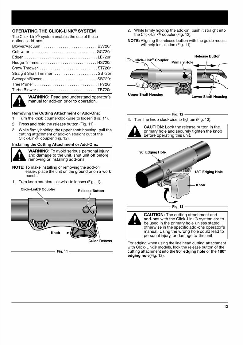
CAUTION: The cutting attachment andadd-ons with the Click-Link® system are tobe used in the primary hole unless statedotherwise in the specific add-ons operator’smanual. Using the wrong hole could lead topersonal injury, or damage to the unit.
For edging when using the line head cutting attachmentwith Click-Link® models, lock the release button of thecutting attachment into the 90° edging hole or the 180°edging hole(Fig. 12).
OPERATING THE CLICK-LINK® SYSTEM
The Click-Link® system enables the use of theseoptional add-ons.
Blower/Vacuum . . . . . . . . . . . . . . . . . . . . . . . . . . BV720r
Cultivator . . . . . . . . . . . . . . . . . . . . . . . . . . . . . . GC720r
Edger . . . . . . . . . . . . . . . . . . . . . . . . . . . . . . . . . . LE720r
Hedge Trimmer . . . . . . . . . . . . . . . . . . . . . . . . . . HS720r
Snow Thrower . . . . . . . . . . . . . . . . . . . . . . . . . . . ST720r
Straight Shaft Trimmer . . . . . . . . . . . . . . . . . . . . SS725r
Sweeper/Blower . . . . . . . . . . . . . . . . . . . . . . . . . SB720r
Tree Pruner . . . . . . . . . . . . . . . . . . . . . . . . . . . . . TP720r
Turbo Blower . . . . . . . . . . . . . . . . . . . . . . . . . . . . TB720r
WARNING: Read and understand operator’smanual for add-on prior to operation.
Removing the Cutting Attachment or Add-Ons:
1. Turn the knob counterclockwise to loosen (Fig. 11).
2. Press and hold the release button (Fig. 11).
3. While firmly holding the upper shaft housing, pull thecutting attachment or add-on straight out of theClick-Link® coupler (Fig. 12).
Installing the Cutting Attachment or Add-Ons:
WARNING: To avoid serious personal injuryand damage to the unit, shut unit off beforeremoving or installing add-ons.
NOTE: To make installing or removing the add-oneasier, place the unit on the ground or on a workbench.
1. Turn knob counterclockwise to loosen (Fig.11).
Fig. 11
Click-Link® Coupler Release Button
Guide Recess
Knob
Primary Hole
Upper Shaft Housing
90˚ Edging Hole
Click-Link® Coupler
2. While firmly holding the add-on, push it straight intothe Click-Link® coupler (Fig. 12).
NOTE: Aligning the release button with the guide recesswill help installation (Fig. 11).
3. Turn the knob clockwise to tighten (Fig. 13).CAUTION: Lock the release button in theprimary hole and securely tighten the knobbefore operating this unit.
Fig. 12
Fig. 13
Knob
180˚ Edging Hole
Lower Shaft Housing
Release Button

8/4/2019 Ryobi 875R 4-Cycle Straight Shaft Trimmer Plus Manual
http://slidepdf.com/reader/full/ryobi-875r-4-cycle-straight-shaft-trimmer-plus-manual 14/30
OPERATING INSTRUCTIONS
14
Each time the head is bumped, about 1 inch (25.4 mm.of trimming line is released. A blade in the cuttingattachment shield will cut the line to the proper length excess line is released.
For best results, tap the Bump Head™ on bare groundor hard soil. If line release is attempted in tall grass, theengine may stall. Always keep the trimming line fully
extended. Line release becomes more difficult as thecutting line becomes shorter.
NOTE: Do not rest the Bump Head™ on the groundwhile the unit is running .
CAUTION: Do not remove or alter the linecutting blade assembly. Excessive line lengtwill make the clutch overheat. This may leadto serious personal injury or damage to theunit.
Some line breakage will occur from:
• Entanglement with foreign matter
• Normal line fatigue
• Attempting to cut thick, stalky weeds
• Forcing the line into objects such as walls or fenceposts
TIPS FOR BEST TRIMMING RESULTS
• Keep the cutting attachment parallel to the ground.
• Do not force the cutting attachment. Allow the tip othe line to do the cutting, especially along walls.Cutting with more than the tip will reduce cuttingefficiency and may overload the engine.
• Cut grass over 8 inches (200 mm) by working fromtop to bottom in small increments to avoidpremature line wear or engine drag.
• Cut from left to right whenever possible. Cutting tothe right improves the unit's cutting efficiency.Clippings are thrown away from the operator.
• Slowly move the trimmer into and out of the cuttingarea at the desired height. Move either in a forwardbackward or side-to-side motion. Cutting shorterlengths produces the best results.
• Trim only when grass and weeds are dry.
• The life of your cutting line is dependent upon;
• Following the previous trimming techniques
• What vegetation is being cut
• Where it’s being cutFor example, the line will wear faster when trimmingagainst a foundation wall as opposed to trimmingaround a tree.
HOLDING THE TRIMMER
WARNING: Always wear eye, hearing, footand body protection to reduce the risk ofinjury when operating this unit.
Before operating the unit, stand in the operating position(Fig. 14). Check for the following:
• The operator is wearing eye protection and properclothing.
• The right arm is slightly bent, and the hand is holdingthe shaft grip.
• The left arm is straight, and the hand is holding theJ-handle.
Fig. 14
• The unit is at waist level.
• The sweeper/blower is parallel to the ground and ispositioned so debris is blown away from operator.
ADJUSTING TRIMMING LINE LENGTH
The Bump Head™ cutting attachment allows you torelease trimming line without stopping the engine. Torelease more line, lightly tap the cutting attachment onthe ground (Fig. 15) while operating the trimmer at highspeed.
NOTE: Always keep the trimming line fully extended.Line release becomes more difficult as cuttingline becomes shorter
Fig. 15

8/4/2019 Ryobi 875R 4-Cycle Straight Shaft Trimmer Plus Manual
http://slidepdf.com/reader/full/ryobi-875r-4-cycle-straight-shaft-trimmer-plus-manual 15/30
OPERATING INSTRUCTIONS
15
WARNING: To prevent serious injury, neverdo maintenance or repairs with unit running.
Always do maintenance and repairs on acool unit. Disconnect spark plug wire toensure the unit will not start.
Fig. 16
DECORATIVE TRIMMING
Decorative trimming is accomplished by removing allvegetation around trees, posts, fences, etc.
Rotate the whole unit so that the cutting attachment is ata 30° angle to the ground (Fig. 16).
NOTE: Some maintenance procedures may requirespecial tools or skills. If you are unsure aboutthese procedures take your unit to an authorizedservice dealer.
MAINTENANCE SCHEDULE
These required maintenance procedures should beperformed at the frequency stated in the table. Theyshould also be included as part of any seasonal tune-up.
MAINTENANCE AND REPAIR INSTRUCTIONS
MAINTENANCE REQUIRED
Fill fuel tank with fresh fuel
Check oil
Clean and re-oil air filter.
Change oil
Change oil
Clean Spark Arrestor
Check rocker arm to valve clearance and adjust asrequired
Check rocker arm to valve clearance and adjust asrequired
Check spark plug condition and gap
FREQUENCY
Before Starting Engine
Every 10 Hours
1st Change at 10 Hours
Every 25 Hours there after
Every 25 Hours
10 hours on new engine
Every 50 Hours
Every 50 Hours
REFER TO:
Page 11
Page 19
Page 20
Page 19
Page 19
Page 24
Page 22-23
Page 22-23
Page 24

8/4/2019 Ryobi 875R 4-Cycle Straight Shaft Trimmer Plus Manual
http://slidepdf.com/reader/full/ryobi-875r-4-cycle-straight-shaft-trimmer-plus-manual 16/30
MAINTENANCE AND REPAIR INSTRUCTIONS
16
Line Locking Hole
Trimming Line
Line Loading Hole
Eyelet
5. Insert the line into the locking hole (Fig. 18). Do notpush the line more than 1/2 inch (12.7 mm) into theline locking hole. When inserted correctly the linewill form a small loop (Fig. 19).
6. Pull the line from the outer spool until the line is tigagainst the inner reel (Fig. 20).
LINE INSTALLATION FOR THE SPEEDSPOOL®
Always use genuine Ryobi 0.080 inch (2.03 mm)replacement line. Line other than specified may makethe engine overheat or fail.
WARNING: Never use metal-reinforced line,wire, or rope, etc. These can break off and
become a dangerous projectile.
There are two methods to replace the SpeedSpool®
trimming line.
• Wind the inner reel with new line
• Install a prewound inner reel
Winding the Inner Reel With New Line
NOTE: It Is unnecessary to remove the bump knob toinstall new trimming line.
1. Cut two pieces of 0.080 inch (2.03 mm) trimmingline, 10 feet (3 m) long.
WARNING: Always use the correct linelength when installing trimming line on theunit. The line may not release properly if theline is too long.
2. Hold the outer spool and turn the inner reelcounterclockwise to line up the arrows on the outerspool and inner reel (Fig. 17).
3. Pull old line out of the line loading and line locking
holes (Figs. 18 and 19).4. Insert a piece of trimming line into one of the two
eyelets in the outer spool. Push it up through the lineloading hole in the inner reel (Fig. 18). Do not bendthe line when inserting it into the eyelet.
Top View Of The SpeedSpool®
Outer Spool
Arrows
Inner Reel
Bump Knob
Fig. 17
Fig. 18
Fig. 20
Fig. 19

8/4/2019 Ryobi 875R 4-Cycle Straight Shaft Trimmer Plus Manual
http://slidepdf.com/reader/full/ryobi-875r-4-cycle-straight-shaft-trimmer-plus-manual 17/30
MAINTENANCE AND REPAIR INSTRUCTIONS
17
Bump Knob
Foam Seal
Spring
Inner Reel
INSTALLING A PREWOUND REEL
1. Turn the Bump Knob counterclockwise and removethe bump knob, spring, and foam seal (Fig. 23).
9. If winding the line becomes difficult or the line jams,pull the ends of the line from the spool (Fig. 22).Continue winding the inner reel counterclockwise .
4. Hold the inner reel in place and install the bumpknob, spring and foam seal. Press down and turn thebump knob clockwise. Grasp the ends and pullfirmly to release the line from the holding slots in theinner reel. (Fig. 22).
Releasing the Inner Reel
If the SpeedSpool® does not release line correctly, pullthe ends of the line firmly from the spool (Fig. 22). If thisdoes not release line, follow the Cleaning theSpeedSpool® instructions.
2. Pull the old inner reel with existing line from the outerspool.
3. Insert the ends of the prewound inner reel line intothe outer spool eyelets (Fig. 24). Push the new innerreel, arrow side up, into the outer spool.
7. Repeat procedures 4-6 with the second piece of line.
8. Hold the outer spool. Wind the inner reelcounterclockwise until approximately four (4) inches(102 mm) of line remain (Fig. 21).
NOTE: Do not wind the inner reel before installing thesecond piece of line.
Fig. 21
Fig. 22
Fig. 23
Fig. 24
8/4/2019 Ryobi 875R 4-Cycle Straight Shaft Trimmer Plus Manual
http://slidepdf.com/reader/full/ryobi-875r-4-cycle-straight-shaft-trimmer-plus-manual 18/30
MAINTENANCE AND REPAIR INSTRUCTIONS
18
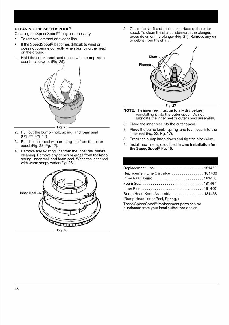
2. Pull out the bump knob, spring, and foam seal(Fig. 23, Pg. 17).
3. Pull the inner reel with existing line from the outerspool (Fig. 23, Pg. 17).
4. Remove any existing line from the inner reel beforecleaning. Remove any debris or grass from the knob,spring, inner reel, and foam seal. Wash the inner reelwith warm soapy water (Fig. 26).
Inner Reel
Shaft
Plunger
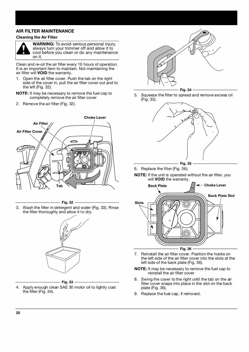
NOTE: The inner reel must be totally dry before
reinstalling it into the outer spool. Do notlubricate the inner reel or outer spool assembly
6. Place the inner reel into the outer spool.
7. Place the bump knob, spring, and foam seal into thinner reel (Fig. 23, Pg. 17).
8. Press the bump knob down and tighten clockwise.
9. Install new line as described in Line Installation fothe SpeedSpool® Pg. 16.
5. Clean the shaft and the inner surface of the outerspool. To clean the shaft underneath the plunger,press down on the plunger (Fig. 27). Remove any dor debris from the shaft.
Fig. 25
Fig. 27
Fig. 26
CLEANING THE SPEEDSPOOL®
Cleaning the SpeedSpool® may be necessary,
• To remove jammed or excess line,
• If the SpeedSpool® becomes difficult to wind ordoes not operate correctly when bumping the headon the ground,
1. Hold the outer spool, and unscrew the bump knobcounterclockwise (Fig. 25).
SPEEDSPOOL® REPLACEMENT PARTS
Replacement Line . . . . . . . . . . . . . . . . . . . . . . . . 18147
Replacement Line Cartridge . . . . . . . . . . . . . . . . 18146
Inner Reel Spring . . . . . . . . . . . . . . . . . . . . . . . . 18146
Foam Seal . . . . . . . . . . . . . . . . . . . . . . . . . . . . . . 18146
Inner Reel . . . . . . . . . . . . . . . . . . . . . . . . . . . . . . 18146
Bump Head Knob Assembly . . . . . . . . . . . . . . . . 18146
(Bump Head, Inner Reel, Spring, )
These SpeedSpool® replacement parts can bepurchased from your local authorized dealer.

8/4/2019 Ryobi 875R 4-Cycle Straight Shaft Trimmer Plus Manual
http://slidepdf.com/reader/full/ryobi-875r-4-cycle-straight-shaft-trimmer-plus-manual 19/30
MAINTENANCE AND REPAIR INSTRUCTIONS
19
CHECKING THE OIL LEVEL
CAUTION: To prevent extensive engine wearand damage to the unit, always maintain theproper oil level in the crankcase. Neveroperate the unit with the oil level below thebottom of the dipstick.
The importance of checking and maintaining the properoil level in the crankcase cannot be overemphasized.Check oil before each use:
1. Stop engine and allow oil to drain into the crankcase.
2. Place the unit on a flat, level surface to get a properoil level reading.
3. Keep dirt, grass clippings, etc., out of the engine.Clean the area around the oil fill plug/dipstick beforeremoving it.
4. Remove the oil fill plug/dipstick and wipe off oil.Reinsert it all the way back in.
5. Remove the oil fill plug/dipstick and check oil level.
Oil should be up to the top of the dipstick (Fig. 28).
6. If the level is low, add a small amount of oil to the oilfill hole and recheck (Fig. 29). Repeat until the oillevel reaches the top of the dipstick.
NOTE: Do not overfill the unit.
Top of Dipstick
O-Ring
Oil Fill Plug/Dipstick
CHANGING THE OIL
For a new engine, change the oil after the first 10 hoursof operation. Change the oil while the engine is stillwarm. The oil will flow freely and carry away moreimpurities.
CAUTION: Wear gloves to prevent injury
when handling the unit.
1. Unplug spark plug boot to eliminate starting
2. Remove the oil fill plug/dipstick.
3. Pour the oil out of the oil fill hole and into a containerby tipping the unit to a vertical position (Fig. 30).
Allow ample time for complete drainage.
Fig. 30
Fig. 28
Fig. 29
NOTE: Make sure the O-ring is in place on the oil fillplug/dipstick when checking and changing theoil (Fig. 29).
Oil Fill Plug/Dipstick
Oil Fill Hole
O-Ring
Full
Add 1.4-1.5 Oz.(41-44 ml)
6. Replace the oil fill plug/dipstick.
7. Reconnect spark plug boot.
Fig. 31
4. Wipe up any oil residue on the unit and clean up anyoil that may have spilled. Dispose of the oilaccording to Federal, State and local regulations.
5. Refill the crankcase with 3.4 fluid ounce (100 ml) ofSAE 30 SF, SG, SH oil.
NOTE: Use the bottle and spout saved from initial use tomeasure the correct amount. 3.4 ounce (100 ml)is approximately to the top of the label on thebottle (Fig. 31). Check the level with the dipstick.If the level is low, add a small amount of oil andrecheck (Fig. 28). Do not overfill.
Fill Level
8/4/2019 Ryobi 875R 4-Cycle Straight Shaft Trimmer Plus Manual
http://slidepdf.com/reader/full/ryobi-875r-4-cycle-straight-shaft-trimmer-plus-manual 20/30
MAINTENANCE AND REPAIR INSTRUCTIONS
20
AIR FILTER MAINTENANCE
Cleaning the Air Filter
WARNING: To avoid serious personal injury,always turn your trimmer off and allow it tocool before you clean or do any maintenanceon it.
Clean and re-oil the air filter every 10 hours of operation.It is an important item to maintain. Not maintaining theair filter will VOID the warranty.
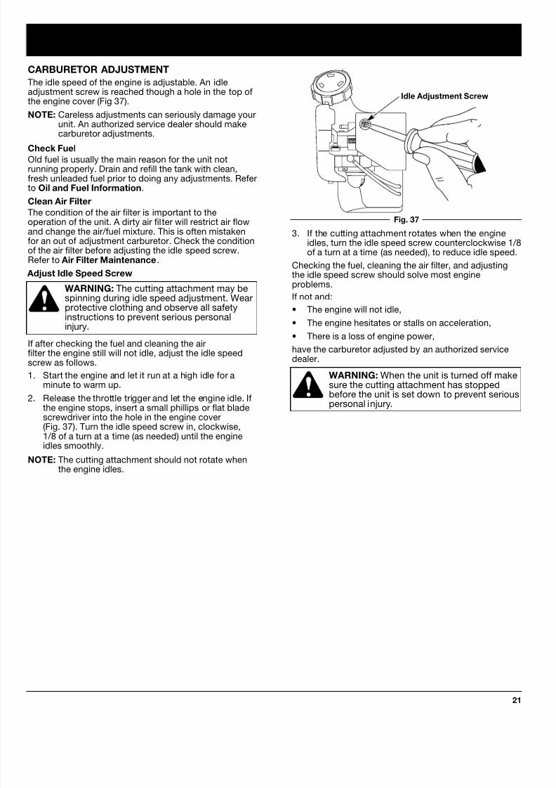
1. Open the air filter cover. Push the tab on the rightside of the cover in, pull the air filter cover out and tothe left (Fig. 32).
NOTE: It may be necessary to remove the fuel cap tocompletely remove the air filter cover
2. Remove the air filter (Fig. 32).
3. Wash the filter in detergent and water (Fig. 33). Rinsethe filter thoroughly and allow it to dry.
4. Apply enough clean SAE 30 motor oil to lightly coatthe filter (Fig. 34).
Air Filter
Choke Lever
Air Filter Cover
Tab
Fig. 32
Fig. 33
Fig. 34
Fig. 35
5. Squeeze the filter to spread and remove excess oil(Fig. 35).
Fig. 36
Back Plate Slo
Slots
Choke Lever
6. Replace the filter (Fig. 36).
NOTE: If the unit is operated without the air filter, youwill VOID the warranty.
7. Reinstall the air filter cover. Position the hooks onthe left side of the air filter cover into the slots at thleft side of the back plate (Fig. 36).
NOTE: It may be necessary to remove the fuel cap toreinstall the air filter cover
8. Swing the cover to the right until the tab on the airfilter cover snaps into place in the slot on the backplate (Fig. 36).
9. Replace the fuel cap, if removed.
Back Plate
8/4/2019 Ryobi 875R 4-Cycle Straight Shaft Trimmer Plus Manual
http://slidepdf.com/reader/full/ryobi-875r-4-cycle-straight-shaft-trimmer-plus-manual 21/30
MAINTENANCE AND REPAIR INSTRUCTIONS
21
CARBURETOR ADJUSTMENT
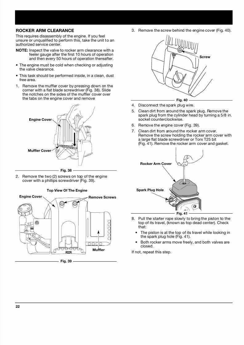
The idle speed of the engine is adjustable. An idleadjustment screw is reached though a hole in the top ofthe engine cover (Fig 37).
NOTE: Careless adjustments can seriously damage yourunit. An authorized service dealer should make
carburetor adjustments.Check Fuel
Old fuel is usually the main reason for the unit notrunning properly. Drain and refill the tank with clean,fresh unleaded fuel prior to doing any adjustments. Referto Oil and Fuel Information.
Clean Air Filter
The condition of the air filter is important to theoperation of the unit. A dirty air filter will restrict air flowand change the air/fuel mixture. This is often mistakenfor an out of adjustment carburetor. Check the conditionof the air filter before adjusting the idle speed screw.Refer to Air Filter Maintenance.
Adjust Idle Speed ScrewWARNING: The cutting attachment may bespinning during idle speed adjustment. Wearprotective clothing and observe all safetyinstructions to prevent serious personalinjury.
If after checking the fuel and cleaning the airfilter the engine still will not idle, adjust the idle speedscrew as follows.
1. Start the engine and let it run at a high idle for aminute to warm up.
2. Release the throttle trigger and let the engine idle. Ifthe engine stops, insert a small phillips or flat bladescrewdriver into the hole in the engine cover(Fig. 37). Turn the idle speed screw in, clockwise,1/8 of a turn at a time (as needed) until the engineidles smoothly.
NOTE: The cutting attachment should not rotate whenthe engine idles.
3. If the cutting attachment rotates when the engineidles, turn the idle speed screw counterclockwise 1/8of a turn at a time (as needed), to reduce idle speed.
Checking the fuel, cleaning the air filter, and adjusting
the idle speed screw should solve most engineproblems.
If not and:
• The engine will not idle,
• The engine hesitates or stalls on acceleration,
• There is a loss of engine power,
have the carburetor adjusted by an authorized servicedealer.
WARNING: When the unit is turned off makesure the cutting attachment has stoppedbefore the unit is set down to prevent seriouspersonal injury.
Idle Adjustment Screw
Fig. 37
8/4/2019 Ryobi 875R 4-Cycle Straight Shaft Trimmer Plus Manual
http://slidepdf.com/reader/full/ryobi-875r-4-cycle-straight-shaft-trimmer-plus-manual 22/30
MAINTENANCE AND REPAIR INSTRUCTIONS
22
4. Disconnect the spark plug wire.
5. Clean dirt from around the spark plug. Remove thespark plug from the cylinder head by turning a 5/8
socket counterclockwise.6. Remove the engine cover (Fig. 39).
7. Clean dirt from around the rocker arm cover.Remove the screw holding the rocker arm cover wia large flat blade screwdriver or Torx T25 bit(Fig. 41). Remove the rocker arm cover and gasket
3. Remove the screw behind the engine cover (Fig. 40
Remove Screws
Rocker Arm Cover
Screw
Fig. 38
Fig. 40
Fig. 41
Engine Cover
Spark Plug Hole
2. Remove the two (2) screws on top of the engine
cover with a phillips screwdriver (Fig. 39).
Fig. 39
Muffler Cover
Engine Cover
Muffler
ROCKER ARM CLEARANCE
This requires disassembly of the engine. If you feelunsure or unqualified to perform this, take the unit to anauthorized service center.
NOTE: Inspect the valve to rocker arm clearance with afeeler gauge after the first 10 hours of operation
and then every 50 hours of operation thereafter.• The engine must be cold when checking or adjusting
the valve clearance.
• This task should be performed inside, in a clean, dustfree area.
1. Remove the muffler cover by pressing down on thecorner with a flat blade screwdriver (Fig. 38). Slidethe notches on the sides of the muffler cover overthe tabs on the engine cover and remove
8. Pull the starter rope slowly to bring the piston to thtop of its travel, (known as top dead center). Checkthat:
• The piston is at the top of its travel while looking inthe spark plug hole (Fig. 41).
• Both rocker arms move freely, and both valves areclosed.
If not, repeat this step.
Top View Of The Engine
8/4/2019 Ryobi 875R 4-Cycle Straight Shaft Trimmer Plus Manual
http://slidepdf.com/reader/full/ryobi-875r-4-cycle-straight-shaft-trimmer-plus-manual 23/30
MAINTENANCE AND REPAIR INSTRUCTIONS
23
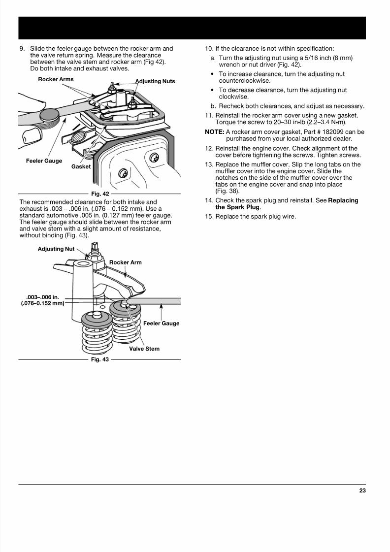
10. If the clearance is not within specification:
a. Turn the adjusting nut using a 5/16 inch (8 mm)wrench or nut driver (Fig. 42).
• To increase clearance, turn the adjusting nutcounterclockwise.
• To decrease clearance, turn the adjusting nut
clockwise.b. Recheck both clearances, and adjust as necessary.
11. Reinstall the rocker arm cover using a new gasket.Torque the screw to 20–30 in•lb (2.2–3.4 N•m).
NOTE: A rocker arm cover gasket, Part # 182099 can bepurchased from your local authorized dealer.
12. Reinstall the engine cover. Check alignment of thecover before tightening the screws. Tighten screws.
13. Replace the muffler cover. Slip the long tabs on themuffler cover into the engine cover. Slide thenotches on the side of the muffler cover over thetabs on the engine cover and snap into place
(Fig. 38).14. Check the spark plug and reinstall. See Replacing
the Spark Plug.
15. Replace the spark plug wire.
9. Slide the feeler gauge between the rocker arm andthe valve return spring. Measure the clearancebetween the valve stem and rocker arm (Fig 42).Do both intake and exhaust valves.
Adjusting Nuts
Feeler Gauge
Rocker Arms
Gasket
Fig. 42
Fig. 43
The recommended clearance for both intake andexhaust is .003 – .006 in. (.076 – 0.152 mm). Use astandard automotive .005 in. (0.127 mm) feeler gauge.The feeler gauge should slide between the rocker armand valve stem with a slight amount of resistance,without binding (Fig. 43).
Feeler Gauge
Adjusting Nut
Rocker Arm
.003–.006 in.(.076–0.152 mm)
Valve Stem

8/4/2019 Ryobi 875R 4-Cycle Straight Shaft Trimmer Plus Manual
http://slidepdf.com/reader/full/ryobi-875r-4-cycle-straight-shaft-trimmer-plus-manual 24/30
MAINTENANCE AND REPAIR INSTRUCTIONS
24
ACCESSORIES/REPLACEMENT PARTS
4-Cycle Oil . . . . . . . . . . . . . . . . . . . . . . . . . . . . . 18178
Oil Fill Plug / Dipstick . . . . . . . . . . . . . . . . . . . . . 18237
Spark Plug . . . . . . . . . . . . . . . . . . . . . . . . . . . . . . 18085
Spark Arrestor Screen . . . . . . . . . . . . . . . . . . . . . 18089
Replacement Line Cartridge . . . . . . . . . . . . . . . . 18146
Inner Reel Spring . . . . . . . . . . . . . . . . . . . . . . . . 18146
Bump Head Knob Assembly . . . . . . . . . . . . . . . . 18146
Fuel Cap . . . . . . . . . . . . . . . . . . . . . . . . . . . . . . . 18108
Shoulder Harness . . . . . . . . . . . . . . . . . . . . . . . . 68207
Click-Link Coupler . . . . . . . . . . . . . . . . . . . . . . . 18161
0.025 in.(0.655 mm.)
REPLACING THE SPARK PLUG
Use only genuine Ryobi spark plugs. The correct air gapis 0.025 in. (0.655 mm.). Remove the plug after every 50hours of operation and check its condition.
1. Stop the engine and allow it to cool. Grasp the plugwire firmly and pull the cap from the spark plug.
2. Clean dirt from around the spark plug. Remove thespark plug from the cylinder head by turning a 5/8 in.socket counterclockwise.
3. Replace cracked, fouled or dirty spark plug. Set theair gap at 0.025 in. (0.655 mm.) using a feeler gauge(Fig. 44).
Fig. 44
CAUTION: Do not sand blast, scrape, or cleanelectrodes. Grit in the engine could damage thecylinder.
4. Install a correctly gaped spark plug in the cylinder
head. Tighten by turning the 5/8 in. socket clockwiseuntil snug.
If using a torque wrench torque to;
110-120 in.•lb. (12.3-13.5 N•m).
Do not over tighten.
NOTE: A replacement spark plug Part # 180852 can bepurchased from your local authorized dealer.
Fig. 45
Muffler Spark Arrestor Screen
Spark Arrestor Cove
ScreTab
Slot
SPARK ARRESTOR MAINTENANCE
1. Remove the muffler cover. See Rocker ArmClearance, Pg. 22.
2. With a flat blade screwdriver or Torx T20 bit, removthe screw attaching the spark arrestor cover to themuffler (Fig. 45).
3. Pull the tab on the spark arrestor cover out of themuffler. Remove the spark arrestor cover.
4. Remove the spark arrestor screen from the sparkarrestor cover.
5. Clean the spark arrestor screen with a wire brush, oreplace.
6. Reinstall the spark arrestor screen, spark arrestorcover, and screw.
NOTE: A replacement spark arrestor screen Part #180890 can be purchased from your localauthorized dealer.

8/4/2019 Ryobi 875R 4-Cycle Straight Shaft Trimmer Plus Manual
http://slidepdf.com/reader/full/ryobi-875r-4-cycle-straight-shaft-trimmer-plus-manual 25/30
CLEANING AND STORAGE
25
LONG TERM STORAGE
If the unit will be stored for an extended time,
1. Drain all gasoline from the gas tank into a container .Do not use gas that has been stored for more than60 days. Dispose of the old gasoline in accordanceto Federal, State, and Local regulations.
2. Start the engine and allow it to run until it stalls. Thisensures that all gasoline has been drained from thecarburetor.
3. Allow the engine to cool. Remove the spark plug andput 1 oz. (30 ml) of high quality motor oil into thecylinder. Pull the starter rope slowly to distribute theoil. Reinstall the spark plug.
NOTE: Remove the spark plug and drain all of the oilfrom the cylinder before attempting to start thetrimmer after storage.
4. Change the oil. See Changing the Oil, Pg. 19.Dispose of the old oil in accordance to Federal,State, and Local regulations.
5. Thoroughly clean the unit and inspect for any looseor damaged parts. Repair or replace damaged partsand tighten loose screws, nuts or bolts. The unit isready for storage.
TRANSPORTING
• Allow the engine to cool before transporting.
• Secure the unit while transporting.
• Drain the gas tank before transporting.
• Tighten gas cap before transporting.
CLEANING
WARNING: To avoid serious personal injury,always turn your trimmer off and allow it tocool before you clean or do any maintenanceon it.
Use a small brush to clean off the outside of the unit. Donot use strong detergents. Household cleaners thatcontain aromatic oils such as pine and lemon, and suchas kerosene, can damage plastic housing or handle.Wipe off any moisture with a soft cloth.
STORAGE
• Never store the unit with gasoline in the tank wherefumes may reach an open flame or spark.
• Allow the engine to cool before storing.
• Store the unit locked up to prevent unauthorized useor damage.
• Store the unit in a dry, well ventilated area.
• Store the unit out of the reach of children.
Store the unit in one of three (3) positions:
1. The unit hanging by the cutting attachment end.
2. The unit hanging by the engine.
3. The unit setting upright on the cutting attachmentshield and engine feet.

8/4/2019 Ryobi 875R 4-Cycle Straight Shaft Trimmer Plus Manual
http://slidepdf.com/reader/full/ryobi-875r-4-cycle-straight-shaft-trimmer-plus-manual 26/30
TROUBLESHOOTING
26
C A U S E A C T I O N
Oil in cutting head Clean the cutting attachment
If further assistance is required, contact your authorized service dealer.
C A U S E A C T I O N
Cutting head bound with grass Stop the engine and clean cutting attachment
Cutting head out of line Refill with new line
Inner reel bound up Replace the inner reel
Cutting head dirty Clean inner reel and outer spoolLine welded Disassemble, remove the welded section
and rewind the line
Line twisted when refilled Disassemble and rewind the line
Not enough line is exposed Push the Bump Knob and pull out line until4 inches (102 mm) of line is outside of thecutting attachment
C A U S E A C T I O N
Old Gasoline Drain fuel tank / Add fresh Gasoline
Improper carburetor adjustment Take to an authorized service dealer forcarburetor adjustment
Clogged Spark Arrestor Screen Clean or Replace. See Pg. 24
C A U S E A C T I O N
Ignition switch is OFF Turn switch to ON
Empty fuel tank Fill fuel tank
Primer bulb wasn't pressed enough Press primer bulb fully and slowly 5-7 times
Engine flooded Use starting procedure with choke lever in theRUN position, Pg. 12
Old Gasoline Drain fuel tank / Add fresh Gasoline
Fouled spark plug Replace or clean the spark plug
ENGINE WILL NOT START
ENGINE WILL NOT IDLE
ENGINE WILL NOT ACCELERATE
ENGINE LACKS POWER OR STALLS WHEN CUTTING
C A U S E A C T I O N
Air Filter is Plugged Replace or clean the air filter
Old Gasoline Drain fuel tank / Add fresh Gasoline
Improper carburetor adjustment Adjust per instruction Pg. 20
C A U S E A C T I O N
Old Gasoline Drain gas tank / Add fresh Gasoline
Improper carburetor adjustment Take to an authorized service dealer forcarburetor adjustment
Cutting head bound with grass Stop the engine and clean the cutting attachment
Dirty air filter Clean or replace the air filter
Clogged Spark Arrestor Screen Clean or Replace. See Pg. 24
CUTTING HEAD WILL NOT ADVANCE LINE
CUTTING LINE ADVANCES UNCONTROLLABLY

8/4/2019 Ryobi 875R 4-Cycle Straight Shaft Trimmer Plus Manual
http://slidepdf.com/reader/full/ryobi-875r-4-cycle-straight-shaft-trimmer-plus-manual 27/30
SPECIFICATIONS
27
ENGINE
Engine Type . . . . . . . . . . . . . . . . . . . . . . . . . . . . . . . . . . . . . . . . . . . . . . . . . . . . . . . . . . . . . . . . . Air-Cooled, 4-Cycle
Displacement . . . . . . . . . . . . . . . . . . . . . . . . . . . . . . . . . . . . . . . . . . . . . . . . . . . . . . . . . . . . . . . . . 1.6 cu. in. (26.2 cc)
Clutch Type . . . . . . . . . . . . . . . . . . . . . . . . . . . . . . . . . . . . . . . . . . . . . . . . . . . . . . . . . . . . . . . . . . . . . . . . . Centrifugal
Operating RPM . . . . . . . . . . . . . . . . . . . . . . . . . . . . . . . . . . . . . . . . . . . . . . . . . . . . . . . . . . . . . . . . . 6,800-7,800 rpmIdle Speed RPM . . . . . . . . . . . . . . . . . . . . . . . . . . . . . . . . . . . . . . . . . . . . . . . . . . . . . . . . . . . . . . . . . . . . . . 2,800 rpm
Ignition Type . . . . . . . . . . . . . . . . . . . . . . . . . . . . . . . . . . . . . . . . . . . . . . . . . . . . . . . . . . . . . . . . . . . . . . . . . Electronic
Ignition Switch . . . . . . . . . . . . . . . . . . . . . . . . . . . . . . . . . . . . . . . . . . . . . . . . . . . . . . . . . . . . . . . . . . . . Rocker Switch
Valve clearance (intake and exhaust) . . . . . . . . . . . . . . . . . . . . . . . . . . . . . . . . . . . . . .003–.006 in. (.076–.0152 mm)
Spark Plug Gap . . . . . . . . . . . . . . . . . . . . . . . . . . . . . . . . . . . . . . . . . . . . . . . . . . . . . . . . . . . . 0.025 inch (0.655 mm)
Lubrication . . . . . . . . . . . . . . . . . . . . . . . . . . . . . . . . . . . . . . . . . . . . . . . . . . . . . . . . . . . . . . . . . . . . . . . . . . SAE 30 Oil
Crankcase Oil Capacity . . . . . . . . . . . . . . . . . . . . . . . . . . . . . . . . . . . . . . . . . . . . . . . . . . . . . . . . . . . . 3.4 oz (100 ml)
Fuel . . . . . . . . . . . . . . . . . . . . . . . . . . . . . . . . . . . . . . . . . . . . . . . . . . . . . . . . . . . . . . . . . . . . . . . . . . . . . . . . Unleaded
Carburetor . . . . . . . . . . . . . . . . . . . . . . . . . . . . . . . . . . . . . . . . . . . . . . . . . . . . . . . . . . . . . . . . Diaphragm, All-Position
Starter . . . . . . . . . . . . . . . . . . . . . . . . . . . . . . . . . . . . . . . . . . . . . . . . . . . . . . . . . . . . . . . . . . . . . . . . . . . . Auto Rewind
Muffler . . . . . . . . . . . . . . . . . . . . . . . . . . . . . . . . . . . . . . . . . . . . . . . . . . . . . . . . . . . . . . . . . . . . . . . Baffled with Guard
Throttle . . . . . . . . . . . . . . . . . . . . . . . . . . . . . . . . . . . . . . . . . . . . . . . . . . . . . . . . . . . . . . . . . . . . Manual Spring Return
Fuel Tank Capacity . . . . . . . . . . . . . . . . . . . . . . . . . . . . . . . . . . . . . . . . . . . . . . . . . . . . . . . . . . . . . . . . . 20 oz (591 ml)
Fuel Tank . . . . . . . . . . . . . . . . . . . . . . . . . . . . . . . . . . . . . . . . . . . . . . . . . . . . . . . . . . . . . . . . . . . . . . . HD Polyethylene
ENGINE
DRIVE SHAFT & CUTTING ATTACHMENT
Drive Shaft Housing . . . . . . . . . . . . . . . . . . . . . . . . . . . . . . . . . . . . . . . . . . . . . . . . . . . . . . Aluminum Tube (Click-Link)
Throttle Control . . . . . . . . . . . . . . . . . . . . . . . . . . . . . . . . . . . . . . . . . . . . . . . . . . . . . . . . . . . . . . . . . Finger-Tip Trigger
Unit Weight (No Fuel, with J-handle, Cutting attachment shield and Cutting attachment) . . . . . . . 13.5 lbs (6.13 kg)
Cutting Mechanism . . . . . . . . . . . . . . . . . . . . . . . . . . . . . . . . . . . . . . . . . . . . . . . . . . . . . . . . Dual String Cutting Head
Line Spool . . . . . . . . . . . . . . . . . . . . . . . . . . . . . . . . . . . . . . . . . . . . . . . . . . . . . . . . . . . . . . . . . . . Bump Line Releaser
Line Spool Diameter . . . . . . . . . . . . . . . . . . . . . . . . . . . . . . . . . . . . . . . . . . . . . . . . . . . . . . . . . . . 3 inches (76.2 mm)
Trimming Line Diameter . . . . . . . . . . . . . . . . . . . . . . . . . . . . . . . . . . . . . . . . . . . . . . . . . . . . . 0.080 inches (2.03 mm)Cutting Path Diameter . . . . . . . . . . . . . . . . . . . . . . . . . . . . . . . . . . . . . . . . . . . . . . . . . . . . . . . . . . 15 inches (38.1 cm)

8/4/2019 Ryobi 875R 4-Cycle Straight Shaft Trimmer Plus Manual
http://slidepdf.com/reader/full/ryobi-875r-4-cycle-straight-shaft-trimmer-plus-manual 28/30
NOTES
28

8/4/2019 Ryobi 875R 4-Cycle Straight Shaft Trimmer Plus Manual
http://slidepdf.com/reader/full/ryobi-875r-4-cycle-straight-shaft-trimmer-plus-manual 29/30 29
The California Air Resources Board and RyobiOutdoor Products (ROP), are pleased to explain theemission control system warranty on your 2000 andlater small off-road engine. In California, new smalloff-road engines must be designed, built andequipped to meet the State's stringent anti-smogstandards. ROP must warrant the emission control
system on your small off-road engine for the periodsof time listed below provided there has been noabuse, neglect or improper maintenance of your smalloff-road engine.
Your emission control system may include parts suchas the carburetor or fuel injection system, the ignitionsystem, and catalytic converter. Also included may behoses, belts, connectors and other emission-relatedassemblies.
Where a warrantable condition exists, ROP will repairyour small off-road engine at no cost to you includingdiagnosis, parts and labor.
The 2000 and later small off-road engines arewarranted for two years. If any emission-related parton your engine is defective, the part will be repairedor replaced by ROP.
OWNER'S WARRANTY RESPONSIBILITIES:
• As the small off-road engine owner, you areresponsible for the performance of the requiredmaintenance listed in your operator's manual. ROPrecommends that you retain all receipts coveringmaintenance on your small off-road engine, butROP cannot deny warranty solely for the lack ofreceipts or for your failure to ensure theperformance of all scheduled maintenance.
• As the small off-road engine owner, you shouldhowever be aware that ROP may deny you warrantycoverage if your small off-road engine or a part hasfailed due to abuse, neglect, improper maintenanceor unapproved modifications.
• You are responsible for presenting your smalloff-road engine to a Ryobi Authorized ServiceCenter as soon as a problem exists. The warrantyrepairs should be completed in a reasonableamount of time, not to exceed 30 days.
If you have any questions regarding your warrantyrights and responsibilities, you should call1-800-345-8746.
MANUFACTURER'S WARRANTY COVERAGE:
• The warranty period begins on the date the engineor equipment is delivered to the retail purchaser.
• The manufacturer warrants to the initial owner andeach subsequent purchaser, that the engine is freefrom defects in material and workmanship which
cause the failure of a warranted part for a period oftwo years.
• Repair or replacement of warranted part will beperformed at no charge to the owner at an
Authorized Ryobi Service Center. For the nearestlocation, please contact Ryobi at: 1-800-345-8746.
• Any warranted part which is not scheduled forreplacement, as required maintenance which isscheduled only for regular inspection to the effect of"Repair or replace as necessary" is warranted forthe warranty period. Any warranted part which isscheduled for replacement as required maintenancewill be warranted for the period of time up to thefirst scheduled replacement point for that part.
• The owner will not be charged for diagnostic laborwhich leads to the determination that a warrantedpart is defective, if the diagnostic work is performedat an Authorized Ryobi Service Center.
• The manufacturer is liable for damages to otherengine components caused by the failure of awarranted part still under warranty.
• Failures caused by abuse, neglect or impropermaintenance are not covered under warranty.
• The use of add-on or modified parts can begrounds for disallowing a warranty claim. Themanufacturer is not liable to cover failures or
warranted parts caused by the use of add-on ormodified parts.
• In order to file a claim, go to your nearest Authorized Ryobi Service Center. Warranty servicesor repairs will be provided at all Authorized RyobiService Centers.
• Any manufacturer approved replacement partmay be used in the performance of any warrantymaintenance or repair of emission related partsand will be provided without charge to the owner.
Any replacement part that is equivalent inperformance or durability may be used innon-warranty maintenance or repair and will
not reduce the warranty obligations of themanufacturer.
• The following components are included in theemission related warranty of the engine, air filter,carburetor, primer, fuel lines, fuel pick up/fuel filter,ignition module, spark plug and muffler.
CALIFORNIA EMISSION CONTROL WARRANTY STATEMENT
YOUR WARRANTY RIGHTS AND OBLIGATIONS

8/4/2019 Ryobi 875R 4-Cycle Straight Shaft Trimmer Plus Manual
http://slidepdf.com/reader/full/ryobi-875r-4-cycle-straight-shaft-trimmer-plus-manual 30/30
ALL IMPLIED WARRANTIES ARE LIMITED INDURATION TO THE TWO (2) YEAR WARRANTYPERIOD OR NINETY (90) DAYS FOR PRODUCTSUSED FOR ANY COMMERCIAL PURPOSE.
ACCORDINGLY, ANY SUCH IMPLIED WARRANTIESINCLUDING MERCHANTABILITY, FITNESS FOR APARTICULAR PURPOSE, OR OTHERWISE, AREDISCLAIMED IN THEIR ENTIRETY AFTER THEEXPIRATION OF THE APPROPRIATE TWO-YEAR
OR NINETY DAY WARRANTY PERIOD. RYOBI’SOBLIGATION UNDER THIS WARRANTY, IS STRICTLY
AND EXCLUSIVELY LIMITED TO THE REPAIR ORREPLACEMENT OF DEFECTIVE PARTS, AND ROPDOES NOT ASSUME OR AUTHORIZE ANYONE TO
ASSUME FOR THEM ANY OTHER OBLIGATION.SOME STATES DO NOT ALLOW LIMITATIONS ONHOW LONG AN IMPLIED WARRANTY LASTS, SOTHE ABOVE LIMITATION MAY NOT APPLY TO YOU.
RYOBI ASSUMES NO RESPONSIBILITY FORINCIDENTAL, CONSEQUENTIAL OR OTHERDAMAGES INCLUDING, BUT NOT LIMITED TOEXPENSE OF RETURNING THE RYOBI PRODUCTTO AN AUTHORIZED SERVICE DEALER AND
EXPENSE OF DELIVERING IT BACK TO THEOWNER, MECHANIC’S TRAVEL TIME, TELEPHONEOR TELEGRAM CHARGES, RENTAL OF A LIKEPRODUCT DURING THE TIME WARRANTY SERVICEIS BEING PERFORMED, TRAVEL, LOSS OR DAMAGETO PERSONAL PROPERTY, LOSS OF REVENUE,LOSS OF USE OF THE PRODUCT, LOSS OF TIME,OR INCONVENIENCE. SOME STATES DO NOT
ALLOW THE EXCLUSION OR LIMITATION OFINCIDENTAL OR CONSEQUENTIAL DAMAGES, SOTHE ABOVE LIMITATION OR EXCLUSION MAY NOT
APPLY TO YOU.
This warranty gives you specific legal rights, and youmay also have other rights which vary from state to
state.This warranty applies to all RYOBI Productsmanufactured by RYOBI and sold in the United Statesand Canada.
To locate your nearest service dealer dial1-800-345-8746 in the United States or1-800-265-6778 in Canada.
RYOBI OUTDOOR PRODUCTS
550 N. 54th StreetChandler, AZ 85226 U.S.A.
RYOBI CANADA INC.
275 Industrial RdCambridge, Ontario N1R 6K2 CANADA
RYOBI OUTDOOR PRODUCTS warrants each newRYOBI Product for two (2) years according to thefollowing terms.
This warranty extends to the original retail purchaseronly and commences on the date of original retailpurchase.
Any part of the RYOBI Product manufactured orsupplied by RYOBI and found in the reasonable
judgement of RYOBI to be defective in material orworkmanship will be repaired or replaced by anauthorized RYOBI service dealer without charge forparts and labor.
The RYOBI Product including any defective part mustbe returned to an authorized service dealer within thewarranty period. The expense of delivering the RYOBIProduct to the dealer for warranty work and theexpense of returning it back to the owner after repairor replacement will be paid for by the owner. RYOBI’sresponsibility in respect to claims is limited to makingthe required repairs or replacements and no claim ofbreach of warranty shall be cause for cancellation orrescission of the contract of sale of any RYOBI
Product. Proof of purchase will be required by thedealer to substantiate any warranty claim. All warrantywork must be performed by an authorized RYOBIservice dealer.
This warranty is limited to ninety (90) days from thedate of original retail purchase for any RYOBI Productthat is used for rental or commercial purposes, or anyother income-producing purpose.
This warranty does not cover any RYOBI Product thathas been subject to misuse, neglect, negligence, oraccident, or that has been operated in any waycontrary to the operating instructions as specified inthe RYOBI Operator’s Manual. This warranty does notapply to any damage to the RYOBI Product that is the
result of improper maintenance or to any RYOBIProduct that has been altered or modified so as toadversely affect the product's operation, performanceor durability or that has been altered or modified so asto change its intended use. The warranty does notextend to repairs made necessary by normal wear orby the use of parts or accessories which are eitherincompatible with the RYOBI Product or adverselyaffect its operation, performance or durability.
In addition, this warranty does not cover:
A. Tune-ups - Spark Plugs, Carburetor Adjustments,Filters
B. Wear items - Bump Knobs, Outer Spools,
Cutting Line, Inner Reels, Starter Pulley,Starter Ropes, Drive Belts
RYOBI reserves the right to change or improve thedesign of any RYOBI Product without assumingany obligation to modify any product previouslymanufactured.
SAVE THESE INSTRUCTIONS FOR FUTURE REFERENCE.FOR QUESTIONS CALL 1-800-345-8746 IN U.S.
OR 1-800-265-6778 IN CANADA
LIMITED TWO-YEAR WARRANTY


