50
S-72.238 Wideband CDMA systems (2 cr.) • Responsible teacher Kalle Ruttik Room 205 Otakaari 8. Phone: 451 2356. Email: [email protected]
| Date post: | 17-May-2018 |
| Category: |
Documents |
| Upload: | vuongquynh |
| View: | 215 times |
| Download: | 1 times |
S-72.238 Wideband CDMAsystems (2 cr.)
• Responsible teacherKalle Ruttik
Room 205 Otakaari 8.
Phone: 451 2356.
Email: [email protected]
Goals of the course
• To present the driving factors and ideas behind thedevelopment of third generation cellular system standards.
• To describe the characteristics of CDMA, its possibilitiesand problems in a multipath radio channel.
• To facilitate to understand of the WCDMA concept asapplied to the UMTS UTRA.
• To give an overview of the UMTS core and radio accessnetwork.
Literature
The Course book: “WCDMA for UMTS. Radio Access ForThird Generation Mobile Communications.” Edited by:H.Holma, A. Toskala. 2000, John Wiley&Sons. 322 pp.
Also good reading:
“UMTS Networks. Architecture, Mobility and Services.” H.Kaarinen et.al.. 2001,John Wiley&Sons. 302 pp.
“Radio Network Planning and Optimisation for UMTS.”J.Laiho. et. al.. 2002. John Wiley&Sons. 484 pp.
“The UMTS Network and Radio Access Technology.” J.P.Castro. 2001,John Wiley&Sons. 354 pp.
Specifications http://www.3gpp.org/
Outline of the course
1. Introduction to 3G cellular systems. Cellular propagation environment for 3Gradio links. Standardisation process.
2. Evolution from GSM to UMTS. UMTS network Architecture.
3. Packet traffic modelling.
4. Introduction to WCDMA: modulation demodulation methods made available atthe network level: handover, power control.
5. Radio Access Network architecture (chapter 5).
6. Physical layer (chapter 6).
7. Radio interface protocols (chapter 7).
8. WCDMA radio network planning (chapter 8).
9. Radio Resource management (chapter 9).
10. Packet access (Chapter 10).
11. Physical Layer performance (Chapter 11).
Outline of the lecture
• History of mobile communication.
• Radio Communication peculiarities.
• Vision for UMTS.
• Standardisation process.
History of mobile communications
• 1873 Maxwells equations.
• 1886 Hertz demonstrates the existence of radio waves.
• 1895 Marconi patents the wireless telegraph.
• 1900 Fessenden succeeds to transmit voice over radio:– Ship to shore radio communication,
– Aircraft to ground radio communication.
• 1921 Police car radios, Detroit. – First private radio telephone systems.
• 1946 First public radio telephone systems, St. Louis.
• Introduction of HF radio telephones.
• Introduction of VHF radio telephones.
• 1970 Introduction of Finnish ARP-network
History of mobile communications 2
1979 Introduction of AMPS cellular networks.
1980 POCSAG paging standard.
1982 INMARSAT services.
1982 NMT450 cellular networks.
1984 TACS cellular networks,
CT1 cordless telephones.
1985 CT2 cordless telephones.
1991 GSM cellular networks.
1992 DECT cordless telephones.
1995 First CDMA network.
1995 ERMES paging network
1996 TETRA networks.
1991 Development of FPLMTS/IMT2000 and UMTS standards.
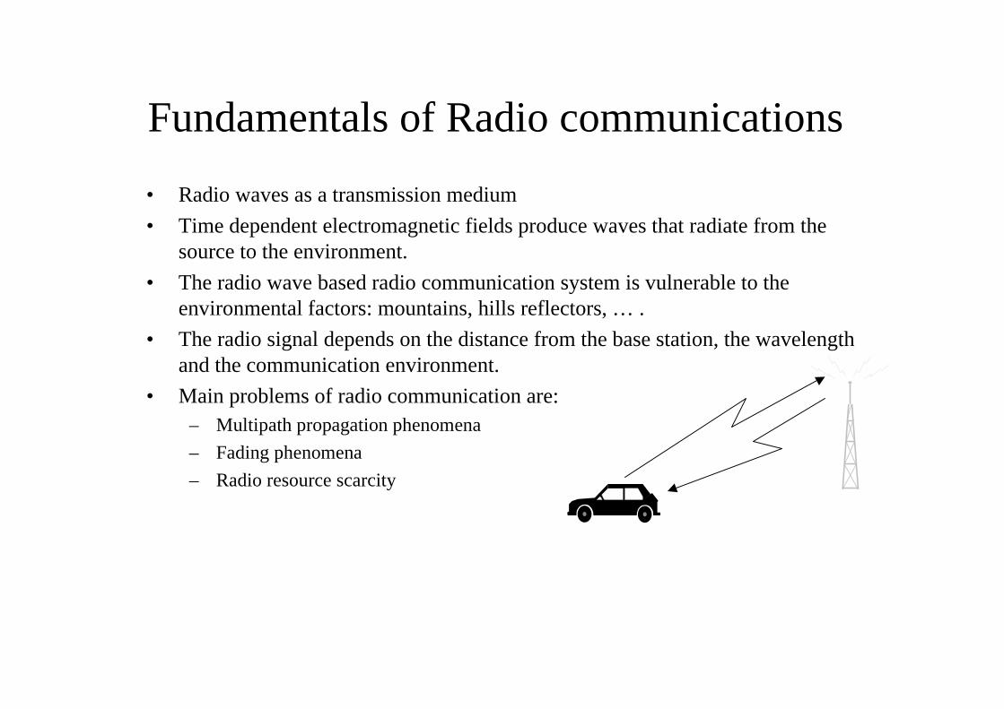
Fundamentals of Radio communications
• Radio waves as a transmission medium
• Time dependent electromagnetic fields produce waves that radiate from thesource to the environment.
• The radio wave based radio communication system is vulnerable to theenvironmental factors: mountains, hills reflectors, … .
• The radio signal depends on the distance from the base station, the wavelengthand the communication environment.
• Main problems of radio communication are:– Multipath propagation phenomena
– Fading phenomena
– Radio resource scarcity
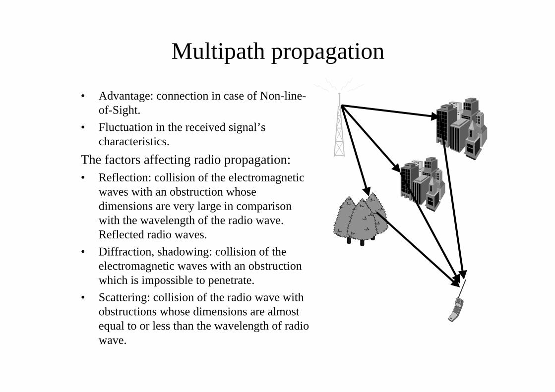
Multipath propagation
• Advantage: connection in case of Non-line-of-Sight.
• Fluctuation in the received signal’scharacteristics.
The factors affecting radio propagation:• Reflection: collision of the electromagnetic
waves with an obstruction whosedimensions are very large in comparisonwith the wavelength of the radio wave.Reflected radio waves.
• Diffraction, shadowing: collision of theelectromagnetic waves with an obstructionwhich is impossible to penetrate.
• Scattering: collision of the radio wave withobstructions whose dimensions are almostequal to or less than the wavelength of radiowave.
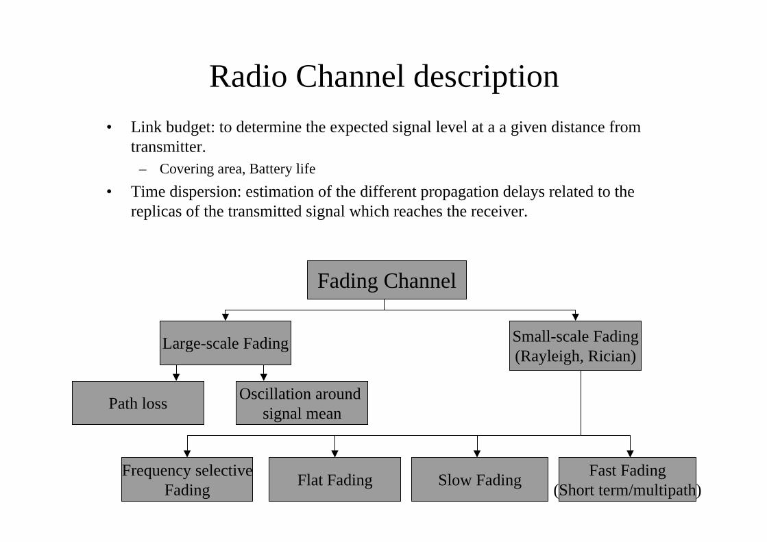
Radio Channel description• Link budget: to determine the expected signal level at a a given distance from
transmitter.– Covering area, Battery life
• Time dispersion: estimation of the different propagation delays related to thereplicas of the transmitted signal which reaches the receiver.
Fading Channel
Large-scale Fading Small-scale Fading(Rayleigh, Rician)
Oscillation around signal mean
Path loss
Frequency selectiveFading
Flat Fading Slow FadingFast Fading
(Short term/multipath)
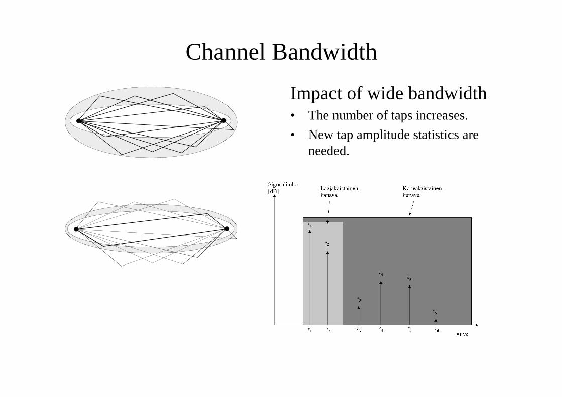
Channel Bandwidth
Impact of wide bandwidth• The number of taps increases.
• New tap amplitude statistics areneeded.
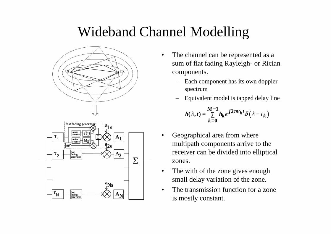
Wideband Channel Modelling
• The channel can be represented as asum of flat fading Rayleigh- or Riciancomponents.
– Each component has its own dopplerspectrum
– Equivalent model is tapped delay line
• Geographical area from wheremultipath components arrive to thereceiver can be divided into ellipticalzones.
• The with of the zone gives enoughsmall delay variation of the zone.
• The transmission function for a zoneis mostly constant.
tx rx
A1
A
A
noisesource
noisesource
Σ
90
fast fading generator
fastfadinggenerator
fastfadinggenerator
2
N
a1s
a2s
aNs
( )1 2
0( , ) k
M j tk k
kh t h e πνλ δ λ τ
−
== −∑
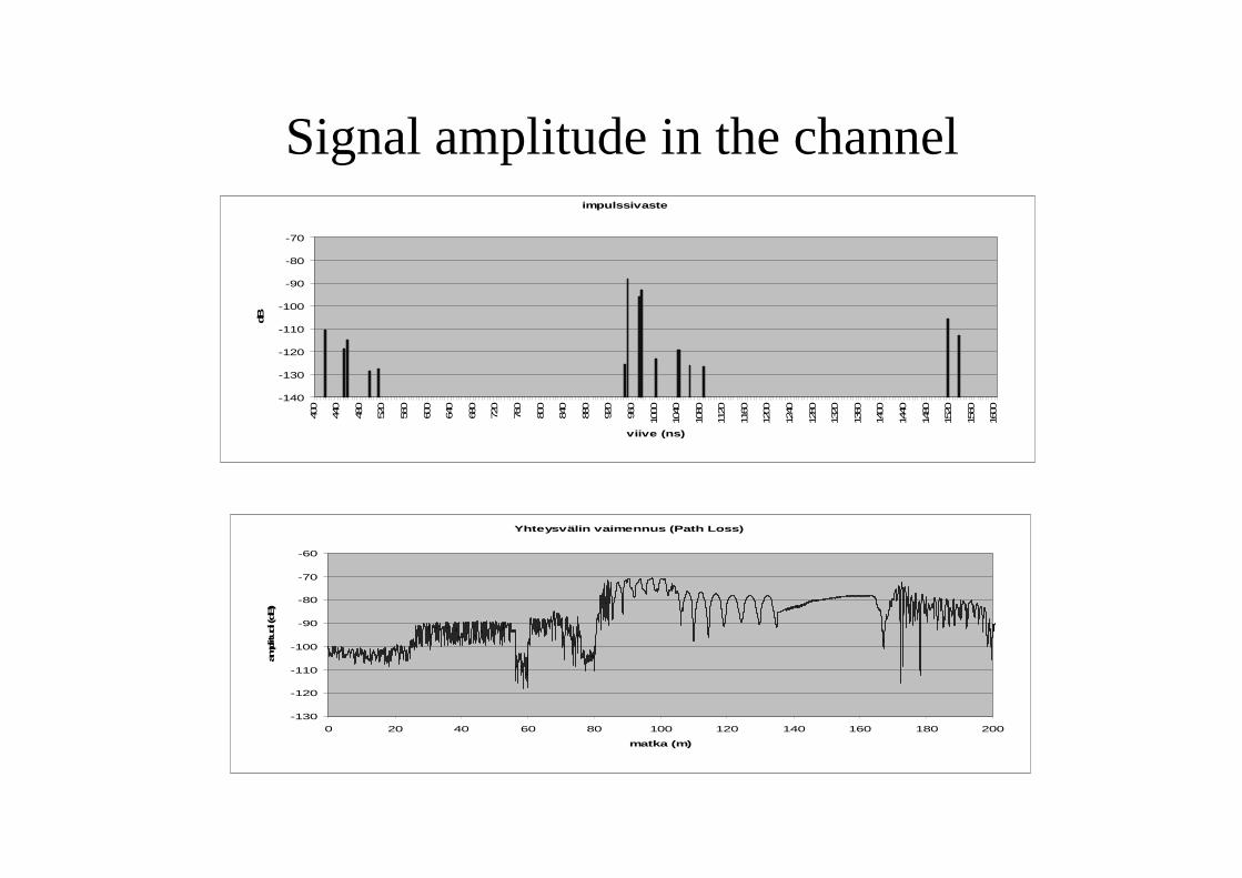
Signal amplitude in the channel
Yhteysvälin vaimennus (Path Loss)
-130
-120
-110
-100
-90
-80
-70
-60
0 20 40 60 80 100 120 140 160 180 200
matka (m)
amplitudi (d
B)
impulssivaste
-140
-130
-120
-110
-100
-90
-80
-70
400
440
480
520
560
600
640
680
720
760
800
840
880
920
960
1000
1040
1080
1120
1160
1200
1240
1280
1320
1360
1400
1440
1480
1520
1560
1600
viive (ns)
dB
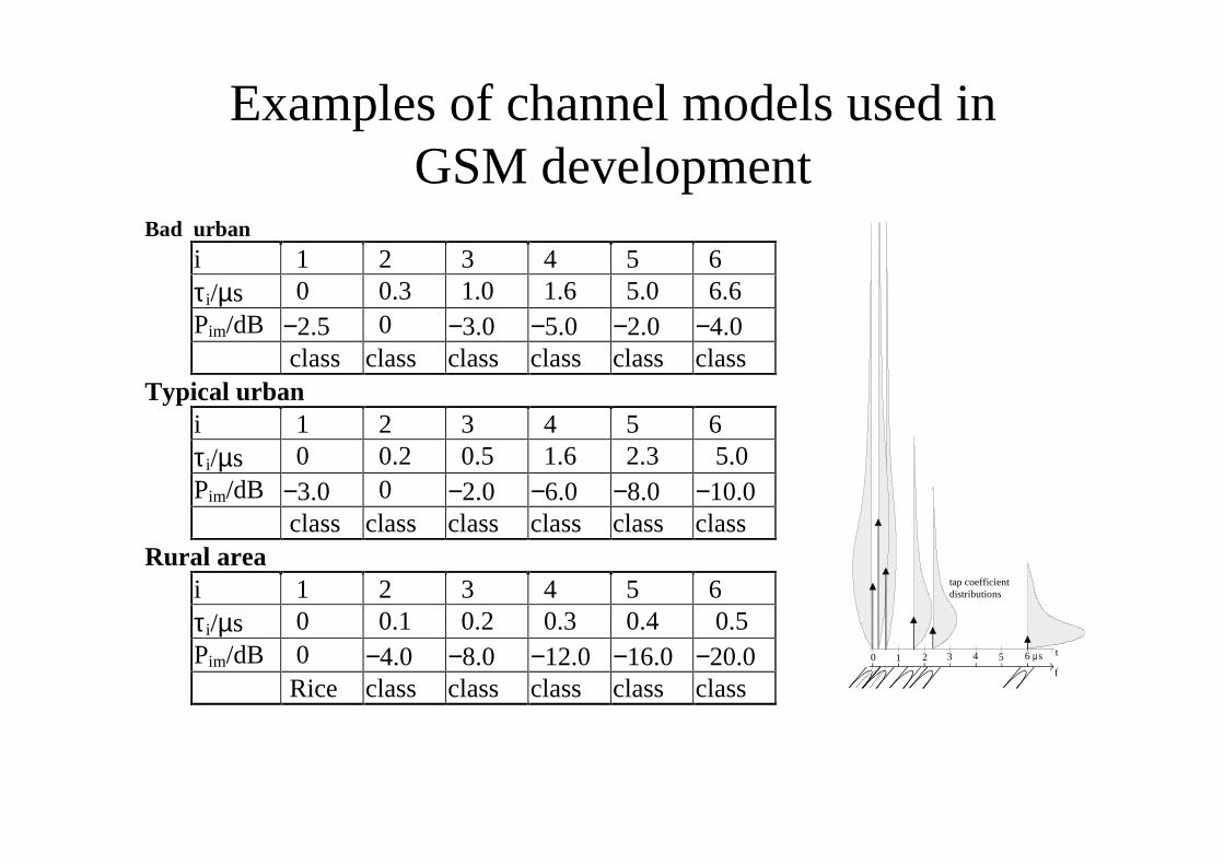
Examples of channel models used inGSM development
Bad urbani 1 2 3 4 5 6τ i/µs 0 0.3 1.0 1.6 5.0 6.6Pim/dB −2.5 0 −3.0 −5.0 −2.0 −4.0
class class class class class classTypical urban
i 1 2 3 4 5 6τ i/µs 0 0.2 0.5 1.6 2.3 5.0Pim/dB −3.0 0 −2.0 −6.0 −8.0 −10.0
class class class class class classRural area
i 1 2 3 4 5 6τ i/µs 0 0.1 0.2 0.3 0.4 0.5Pim/dB 0 −4.0 −8.0 −12.0 −16.0 −20.0
Rice class class class class class
t
f
0 1 2 3 4 5 6 µs
tap coefficientdistributions
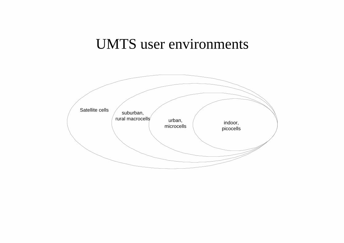
UMTS user environments
suburban,rural macrocells
Satellite cells
urban,microcells
indoor,picocells
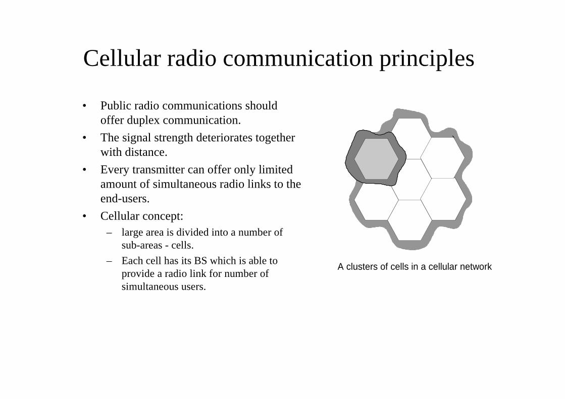
Cellular radio communication principles
• Public radio communications shouldoffer duplex communication.
• The signal strength deteriorates togetherwith distance.
• Every transmitter can offer only limitedamount of simultaneous radio links to theend-users.
• Cellular concept:– large area is divided into a number of
sub-areas - cells.
– Each cell has its BS which is able toprovide a radio link for number ofsimultaneous users.
A clusters of cells in a cellular network
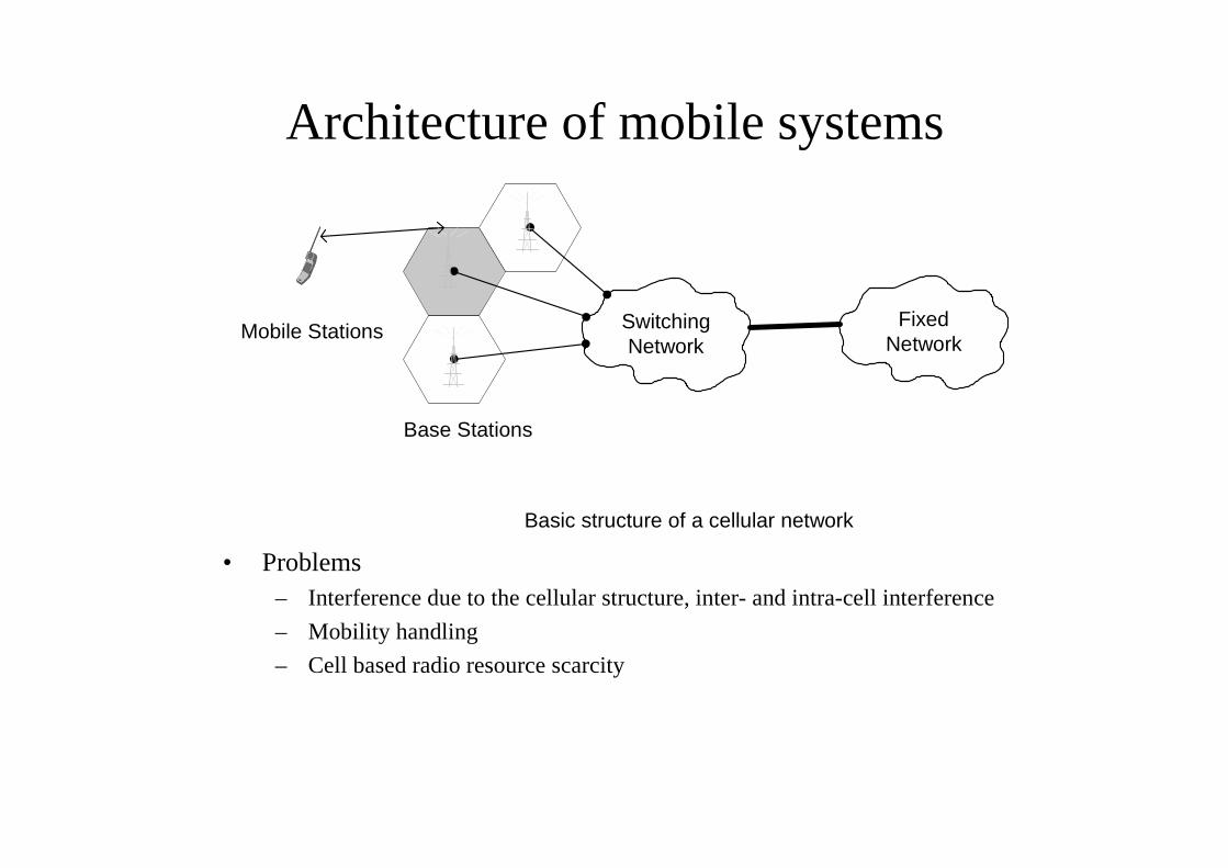
Architecture of mobile systems
• Problems– Interference due to the cellular structure, inter- and intra-cell interference
– Mobility handling
– Cell based radio resource scarcity
Basic structure of a cellular network
SwitchingNetwork
FixedNetwork
Base Stations
Mobile Stations
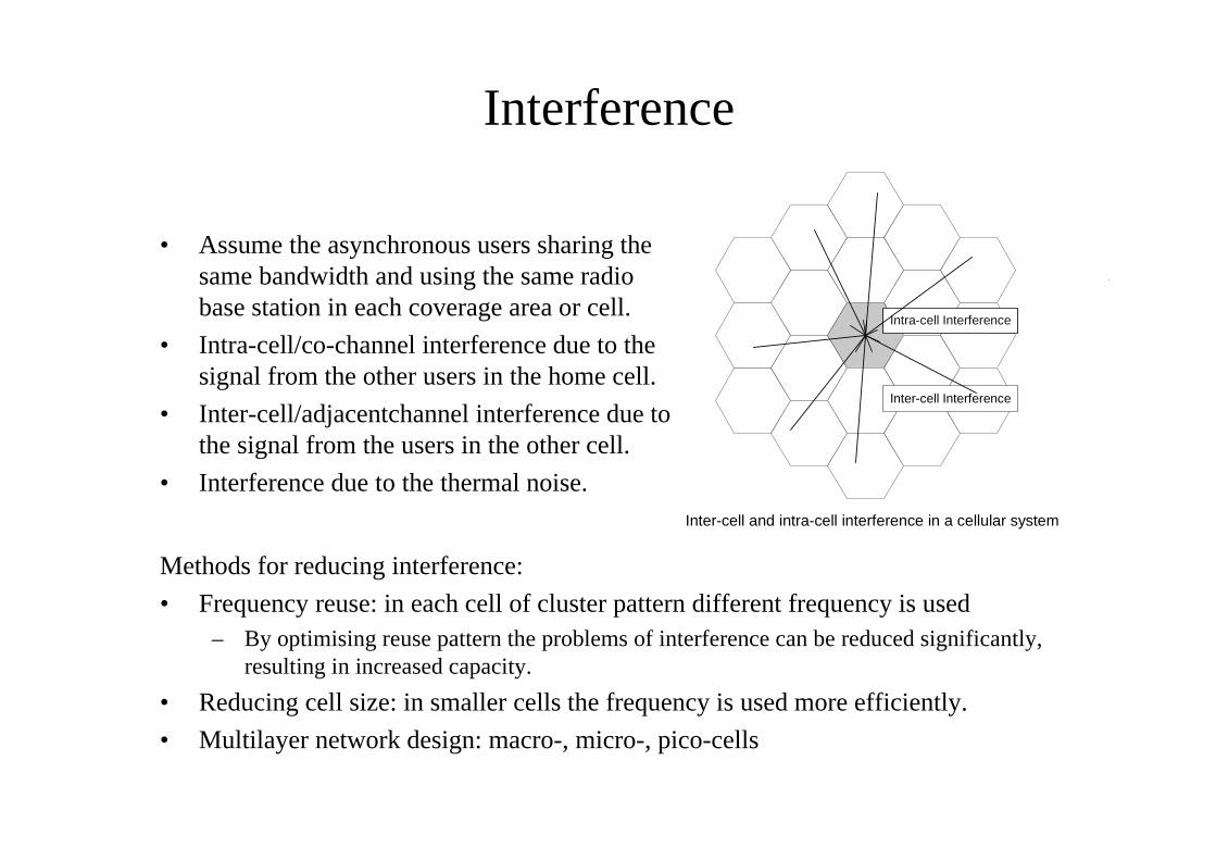
Interference
• Assume the asynchronous users sharing thesame bandwidth and using the same radiobase station in each coverage area or cell.
• Intra-cell/co-channel interference due to thesignal from the other users in the home cell.
• Inter-cell/adjacentchannel interference due tothe signal from the users in the other cell.
• Interference due to the thermal noise.Inter-cell and intra-cell interference in a cellular system
lIntra-cell Interference
Inter-cell Interference
Methods for reducing interference:
• Frequency reuse: in each cell of cluster pattern different frequency is used– By optimising reuse pattern the problems of interference can be reduced significantly,
resulting in increased capacity.
• Reducing cell size: in smaller cells the frequency is used more efficiently.
• Multilayer network design: macro-, micro-, pico-cells
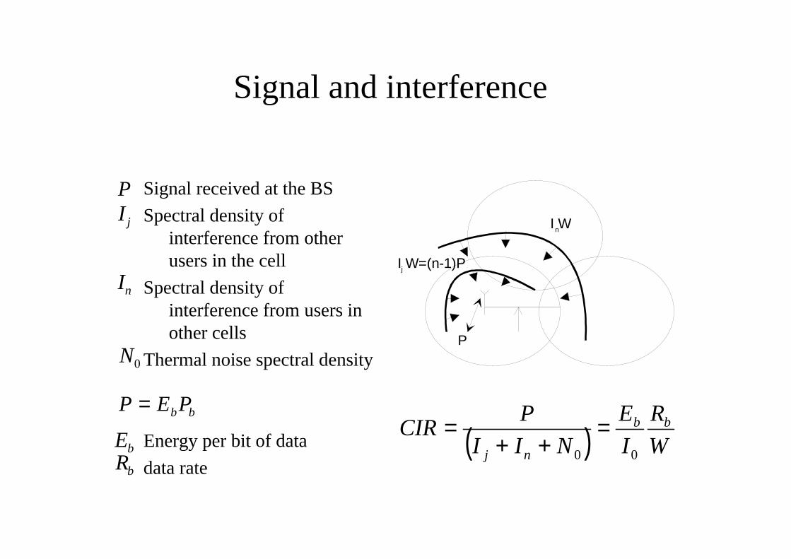
Signal and interference
Signal received at the BS
Spectral density ofinterference from otherusers in the cell
Spectral density ofinterference from users inother cells
Thermal noise spectral density
Energy per bit of data
data rate
I W=(n-1)P
I W
j
n
P
I j
In
P
N0
Rb
Eb
bbPEP =
( ) W
R
I
E
NII
PCIR bb
nj 00
=++
=
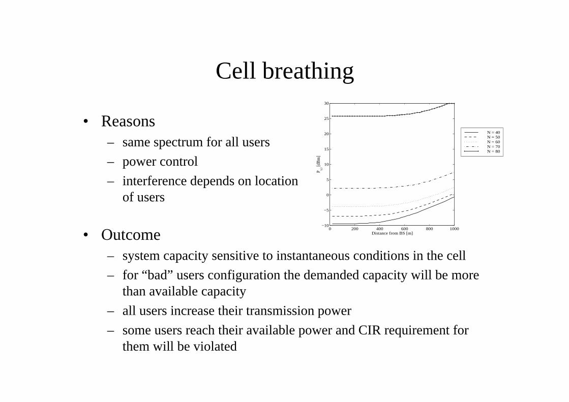
Cell breathing
• Outcome– system capacity sensitive to instantaneous conditions in the cell
– for “bad” users configuration the demanded capacity will be morethan available capacity
– all users increase their transmission power
– some users reach their available power and CIR requirement forthem will be violated
• Reasons– same spectrum for all users
– power control
– interference depends on locationof users
0 200 400 600 800 1000−10
−5
0
5
10
15
20
25
30
Distance from BS [m]
P s,i [d
Bm
]
N = 40N = 50N = 60N = 70N = 80
Mobility
• Mobility provides the possibility of being reachable anywhere and any time forthe end-user
The mobility is provided through:
• Handover: gurantees that whenever the mobile is moving from one BSarea/cell to another, the signal is handed over to the target BS.
When there is no continuous active radio link between mobile and BS the mobilityis supported by:
• Location update: user registers in the network that it can be found in givenarea. Mobile always initiates the location update procedure.
• Paging: indication to the user about the the need for transaction. Pagingprocedure is always initiated by the network.
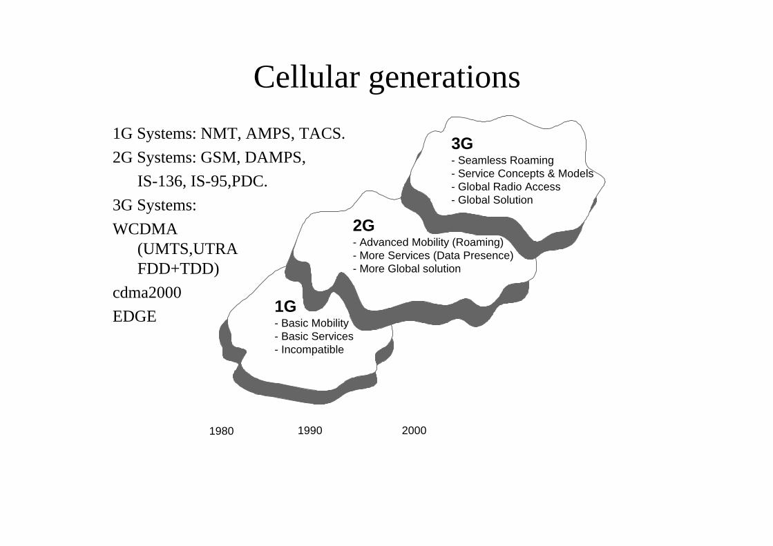
Cellular generations
1G- Basic Mobility- Basic Services- Incompatible
2G- Advanced Mobility (Roaming)- More Services (Data Presence)- More Global solution
3G- Seamless Roaming- Service Concepts & Models- Global Radio Access- Global Solution
1980 1990 2000
1G Systems: NMT, AMPS, TACS.
2G Systems: GSM, DAMPS,
IS-136, IS-95,PDC.
3G Systems:
WCDMA(UMTS,UTRAFDD+TDD)
cdma2000
EDGE
Vision for UMTS
• Well specified system with major interfaces open and standardised. Thespecifications generated should be valid world-wide.
• Added value to the GSM. However, in the beginning the system must bebackward compatible at least with GSM and ISDN.
• Multimedia and all of its components must be supported throughout the system
• The radio access of the 3G must provide wideband capacity be generic enoughin order to become available world-wide. The term “wideband” was adopted toreflect the capacity requirements between 2G narrowband capacity and thebroadband capacity of the fixed communications media.
• The services for end-users must be independent from radio access technologydetails an the network infrastructure must not limit the services to begenerated. That is, the technology platform is one issue and the services usingthe platform are totally another issue.
User aspects of UMTS• reaching mass market
• common standards enabling– low cost mass production
– open interfaces
• global standards
• public and private networks
• ubiquitous services
Mobile aspects of UMTS• terminal mobility
• personal mobility
• service mobility
Telecommunication aspects of UMTS• System providers:
– connection everywhere
– interconnection between networks
– billing and accounting functions for all variousinterest
– security
– Network management is cost efficient andspectrum efficient manner
• Service choice and flexibility thorough a largevariety of service providers and networkoperators.
• Simple and user friendly access.
• Personalised of user service profiles and userinterfaces.
• Transparent services.
• Universal accessibility.
• Convergence of telecommunications, computertechnology, and content provision
• Multimedia services
Examples of new services or applicationsInformation services:
• Interactive shopping,
• On-line equivalents of printed media,
• Location based broadcasting,
• services.
Educational services:
• Virtual schools,
• On-line library,
• Training.
Entertainment services:
• audio on demand,
• games on demand.
Community services
• emergency services,
• governmental procedures.
Business information:
• mobile office,
• virtual workshop.
Special services:
• tele-medicine,
• security monitoring,
• instant help line,
• personal administration.
Communication services:
• video telephony,
• video conference,
• personal location.
Business and financial services
• virtual banking,
• on-line billing.
3G technical requirements• Bit Rate:
– Rural outdoor 144 kbps (500 km/h).
– Suburban outdoor 384 kbps (120 km/h) .
– Indoor 2 Mbps (10 km/h).
• Variable bit rate capability: granularity, circuit and packet bearers.
• Service Multiplexing.
• Varying delay and quality of service requirements. ( priorities of traffic).
• Handover: seamless between the cells and different operators. Co-existencewith and handover to 2G systems (with WCDMA to GSM).
• Support of asymmetric traffic.
• High spectrum efficiency.
• Coexistence of FDD and TDD modes.
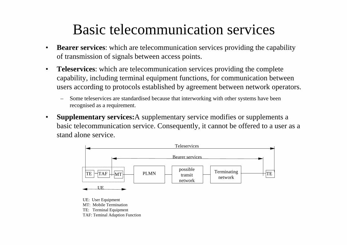
Basic telecommunication services• Bearer services: which are telecommunication services providing the capability
of transmission of signals between access points.
• Teleservices: which are telecommunication services providing the completecapability, including terminal equipment functions, for communication betweenusers according to protocols established by agreement between network operators.
– Some teleservices are standardised because that interworking with other systems have beenrecognised as a requirement.
• Supplementary services:A supplementary service modifies or supplements abasic telecommunication service. Consequently, it cannot be offered to a user as astand alone service.
TE MT PLMNpossibletransit
network
Terminatingnetwork
Bearer services
Teleservices
UE
UE: User EquipmentMT: Mobile TerminationTE: Terminal EquipmentTAF: Teminal Adaption Function
TETAF
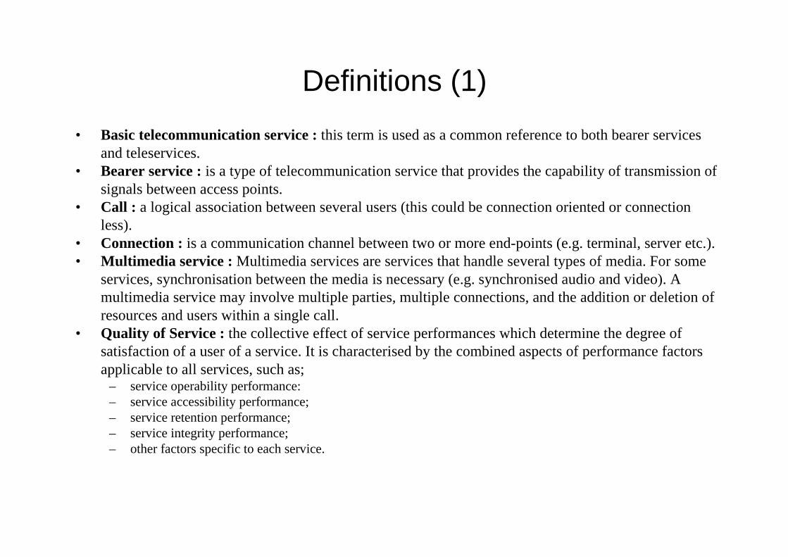
Definitions (1)
• Basic telecommunication service : this term is used as a common reference to both bearer servicesand teleservices.
• Bearer service : is a type of telecommunication service that provides the capability of transmission ofsignals between access points.
• Call : a logical association between several users (this could be connection oriented or connectionless).
• Connection : is a communication channel between two or more end-points (e.g. terminal, server etc.).• Multimedia service : Multimedia services are services that handle several types of media. For some
services, synchronisation between the media is necessary (e.g. synchronised audio and video). Amultimedia service may involve multiple parties, multiple connections, and the addition or deletion ofresources and users within a single call.
• Quality of Service : the collective effect of service performances which determine the degree ofsatisfaction of a user of a service. It is characterised by the combined aspects of performance factorsapplicable to all services, such as;
– service operability performance:– service accessibility performance;– service retention performance;– service integrity performance;– other factors specific to each service.
• Service Capabilities: Bearers defined by parameters, and/or mechanisms needed to realise services.These are within networks and under network control.
• Service Capability Feature: Functionality offered by service capabilities that are accessible via thestandardised application interface
• Services: Services are made up of different service capability features.
• Supplementary service : is a service which modifies or supplements a basic telecommunicationservice. Consequently, it cannot be offered to a user as a standalone service. It shall be offeredtogether with or in association with a basic telecommunication service. The same supplementaryservice may be common to a number of basic telecommunication services.
• Teleservice; is a type of telecommunication service that provides the complete capability, includingterminal equipment functions, for communication between users according to standardised protocolsand transmission capabilities established by agreement between operators.
Definitions (2)
Bearer Services
• Bearer services provide the capability for information transfer between accesspoints and involve only low layer functions.
• The user may choose any set of high layer protocols for his communication.
• A communication link between access points provides a general service forinformation transport.
• The communication link may span over different networks.
• Bearer services are characterised by a set of end-to-end characteristics withrequirements on QoS. QoS is the end-to-end quality of a requested service asperceived by the customer.
• Requirements on the Bearer Services– Information transfer:
• Traffic type: quaranteed/constant bit rate, non-quaranteed/dynamic variable bit rate, realtime dynamic variable bit rate with a minimum guaranteed bit rate.
– Traffic characteristics: the user can require on of the following configurations• Pont-to-point: uni-directional, bi-directional: symmetric, assymmetric.
• Uni-directional point-to-multipoint: multicast,broadcast.
Information quality
• Maximum transfer delay: Transfer delay is the time between the request totransfer the information at one access point to its delivery at the other accesspoint.
• Delay variation: The delay variation of the information received informationover the bearer has to be controlled to support real-time services.
• Bit error ratio: The ratio between incorrect and total transferred informationbits.
• Data rate: The data rate is the amount of data transferred between the twoaccess points in a given period of time.
UMTS QoS Classes
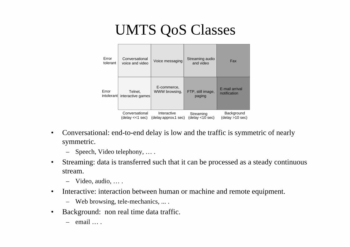
• Conversational: end-to-end delay is low and the traffic is symmetric of nearlysymmetric.
– Speech, Video telephony, … .
• Streaming: data is transferred such that it can be processed as a steady continuousstream.
– Video, audio, … .
• Interactive: interaction between human or machine and remote equipment.– Web browsing, tele-mechanics, ... .
• Background: non real time data traffic.– email … .
Errortolerant
Errorintolerant
Conversational(delay <<1 sec)
Interactive(delay approx.1 sec)
Streaming(delay <10 sec)
Background(delay >10 sec)
Conversationalvoice and video Voice messaging Streaming audio
and video Fax
E-mail arrivalnotificationFTP, still image,
paging
E-commerce,WWW browsing,Telnet,
interactive games
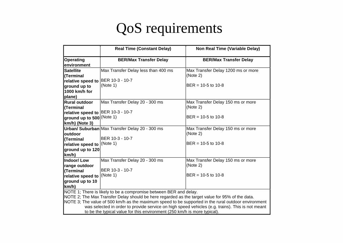
QoS requirementsReal Time (Constant Delay) Non Real Time (Variable Delay)
Operatingenvironment
BER/Max Transfer Delay BER/Max Transfer Delay
Satellite(Terminalrelative speed toground up to1000 km/h forplane)
Max Transfer Delay less than 400 ms
BER 10-3 - 10-7(Note 1)
Max Transfer Delay 1200 ms or more(Note 2)
BER = 10-5 to 10-8
Rural outdoor(Terminalrelative speed toground up to 500km/h) (Note 3)
Max Transfer Delay 20 - 300 ms
BER 10-3 - 10-7(Note 1)
Max Transfer Delay 150 ms or more(Note 2)
BER = 10-5 to 10-8
Urban/ Suburbanoutdoor(Terminalrelative speed toground up to 120km/h)
Max Transfer Delay 20 - 300 ms
BER 10-3 - 10-7(Note 1)
Max Transfer Delay 150 ms or more(Note 2)
BER = 10-5 to 10-8
Indoor/ Lowrange outdoor(Terminalrelative speed toground up to 10km/h)
Max Transfer Delay 20 - 300 ms
BER 10-3 - 10-7(Note 1)
Max Transfer Delay 150 ms or more(Note 2)
BER = 10-5 to 10-8
NOTE 1; There is likely to be a compromise between BER and delay.NOTE 2; The Max Transfer Delay should be here regarded as the target value for 95% of the data.NOTE 3; The value of 500 km/h as the maximum speed to be supported in the rural outdoor environment
was selected in order to provide service on high speed vehicles (e.g. trains). This is not meantto be the typical value for this environment (250 km/h is more typical).
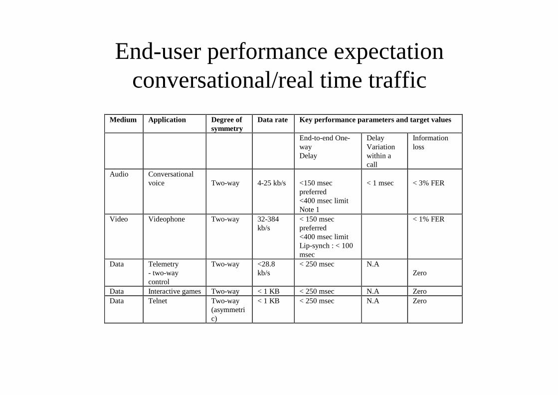
End-user performance expectationconversational/real time traffic
Medium Application Degree ofsymmetry
Data rate Key performance parameters and target values
End-to-end One-wayDelay
DelayVariationwithin acall
Informationloss
Audio Conversationalvoice Two-way 4-25 kb/s <150 msec
preferred<400 msec limitNote 1
< 1 msec < 3% FER
Video Videophone Two-way 32-384kb/s
< 150 msecpreferred<400 msec limitLip-synch : < 100msec
< 1% FER
Data Telemetry- two-waycontrol
Two-way <28.8kb/s
< 250 msec N.AZero
Data Interactive games Two-way < 1 KB < 250 msec N.A ZeroData Telnet Two-way
(asymmetric)
< 1 KB < 250 msec N.A Zero
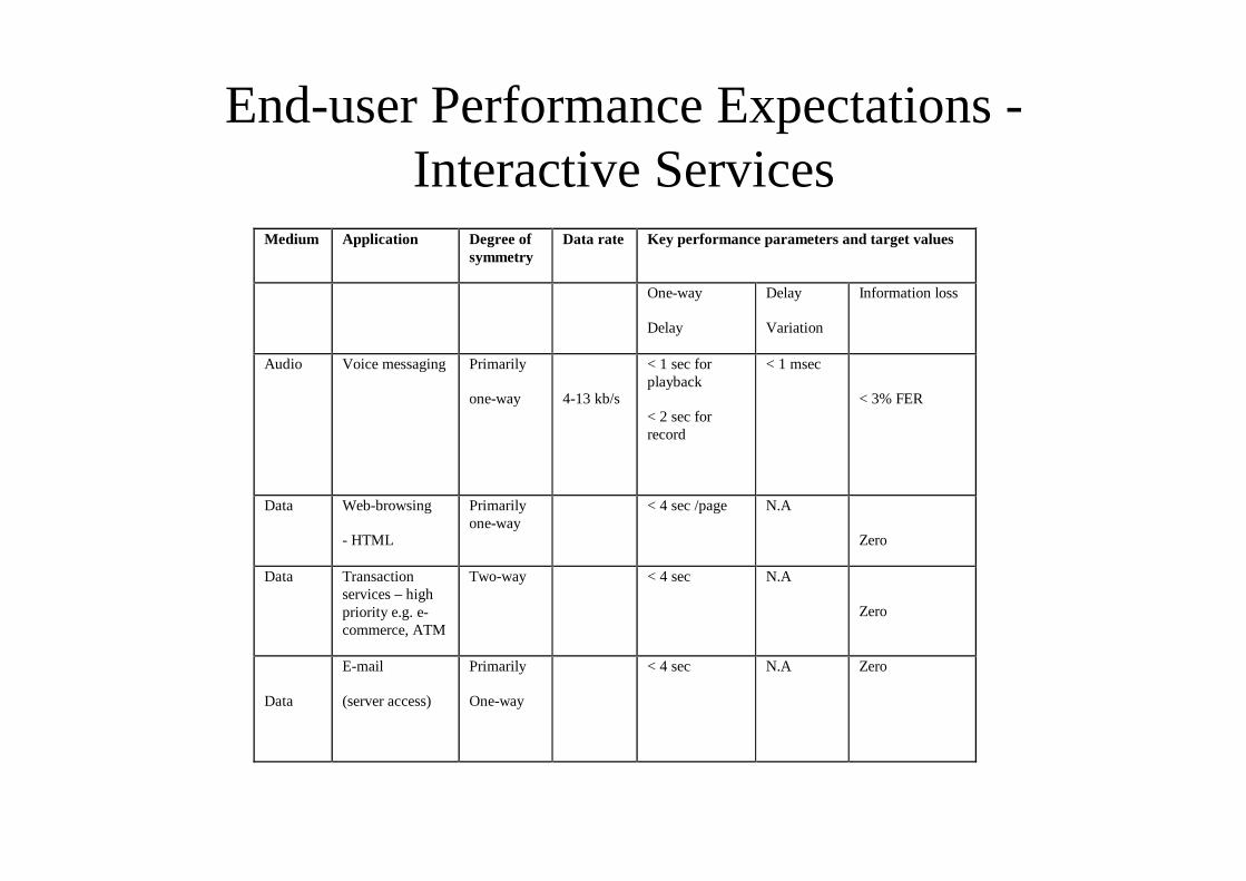
End-user Performance Expectations -Interactive Services
Medium Application Degree ofsymmetry
Data rate Key performance parameters and target values
One-way
Delay
Delay
Variation
Information loss
Audio Voice messaging Primarily
one-way 4-13 kb/s
< 1 sec forplayback
< 2 sec forrecord
< 1 msec
< 3% FER
Data Web-browsing
- HTML
Primarilyone-way
< 4 sec /page N.A
Zero
Data Transactionservices – highpriority e.g. e-commerce, ATM
Two-way < 4 sec N.A
Zero
Data
(server access)
Primarily
One-way
< 4 sec N.A Zero
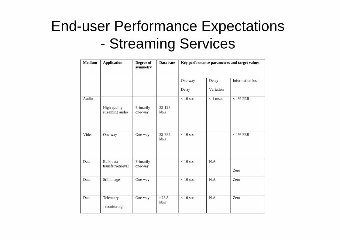
End-user Performance Expectations- Streaming Services
Medium Application Degree ofsymmetry
Data rate Key performance parameters and target values
One-way
Delay
Delay
Variation
Information loss
Audio
High qualitystreaming audio
Primarilyone-way
32-128kb/s
< 10 sec < 1 msec < 1% FER
Video One-way One-way 32-384kb/s
< 10 sec < 1% FER
Data Bulk datatransfer/retrieval
Primarilyone-way
< 10 sec N.A
Zero
Data Still image One-way < 10 sec N.A Zero
Data Telemetry
- monitoring
One-way <28.8kb/s
< 10 sec N.A Zero
Teleservices
• A teleservice can be viewed as set of upper layer capabilities utilising thelower layer capabilities.
• Teleservices can be single media or multimedia services.
• Multimedia services are classified:– multimedia conference services,
– multimedia conversational services,
– multimedia distribution services,
– multimedia retrieval services,
– multimedia messaging services,
– multimedia collection services.
• The terminal and network should support the service.
• The principle of the network design has been that upper layer and lower layerare made as independent as possible. (Layers are understood accordingly OSImodel).
Service Capability features
• Services Capability Features are open, technology independent building blocksaccessible via a standardised application interface.
• Application/Clients access the service capability features via the standardisedapplication interface.
• Framework service capability features: these shall provide commonly usedutilities, necessary for the non-framework service capability features to beaccessible, secure, resilient and manageable.
– Authentication, User-Network Authentication, Application-Network Authentication,User-Application Authentication, Authorisation, Application-Network Authorisation,User-Application Authorisation, Registration, Discovery, Notification. TS22.121.
• Non-Framework service capability features: these shall enable the applicationsto make use of the functionality of the underlying network capabilities (e.g. UserLocation service capability features).
– Session Control, Security/Privacy, Address Translation, Location, User Status, TerminalCapabilities, Messaging, Data Download, User Profile Management, Charging.
• When applications use the generic service capability features, these applicationsbecome independent of (portable over) underlying service capabilities.
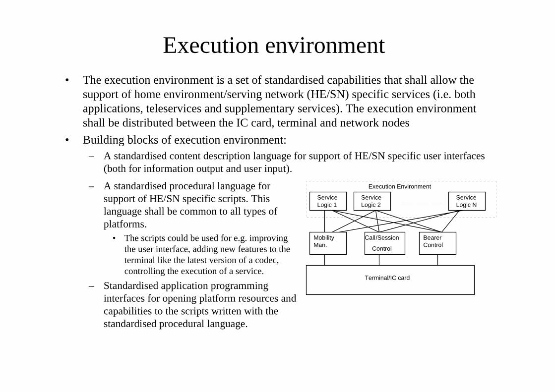
Execution environment• The execution environment is a set of standardised capabilities that shall allow the
support of home environment/serving network (HE/SN) specific services (i.e. bothapplications, teleservices and supplementary services). The execution environmentshall be distributed between the IC card, terminal and network nodes
• Building blocks of execution environment:– A standardised content description language for support of HE/SN specific user interfaces
(both for information output and user input).
MobilityMan.
Call
Control
BearerControl
Service
Execution Environment
Terminal/IC card
/Session
Logic 1ServiceLogic 2
ServiceLogic N
– A standardised procedural language forsupport of HE/SN specific scripts. Thislanguage shall be common to all types ofplatforms.
• The scripts could be used for e.g. improvingthe user interface, adding new features to theterminal like the latest version of a codec,controlling the execution of a service.
– Standardised application programminginterfaces for opening platform resources andcapabilities to the scripts written with thestandardised procedural language.
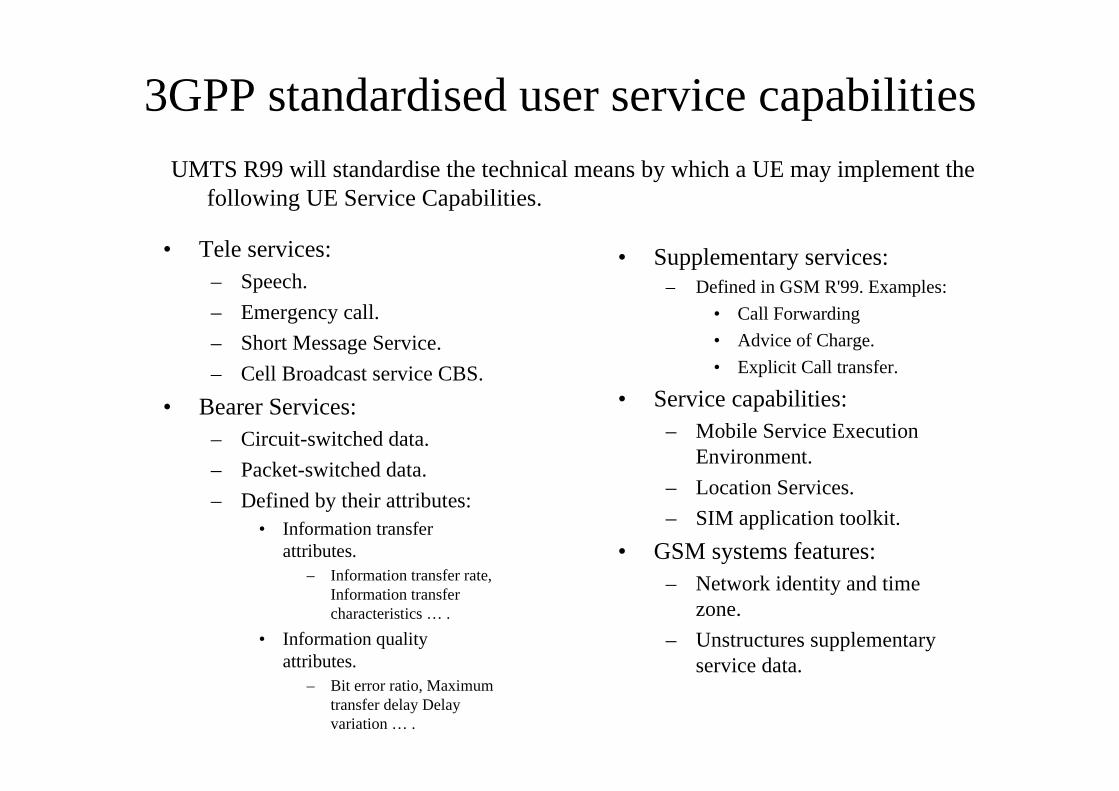
3GPP standardised user service capabilities
• Tele services:– Speech.
– Emergency call.
– Short Message Service.
– Cell Broadcast service CBS.
• Bearer Services:– Circuit-switched data.
– Packet-switched data.
– Defined by their attributes:• Information transfer
attributes.– Information transfer rate,
Information transfercharacteristics … .
• Information qualityattributes.
– Bit error ratio, Maximumtransfer delay Delayvariation … .
• Supplementary services:– Defined in GSM R'99. Examples:
• Call Forwarding
• Advice of Charge.
• Explicit Call transfer.
• Service capabilities:– Mobile Service Execution
Environment.
– Location Services.
– SIM application toolkit.
• GSM systems features:– Network identity and time
zone.
– Unstructures supplementaryservice data.
UMTS R99 will standardise the technical means by which a UE may implement thefollowing UE Service Capabilities.
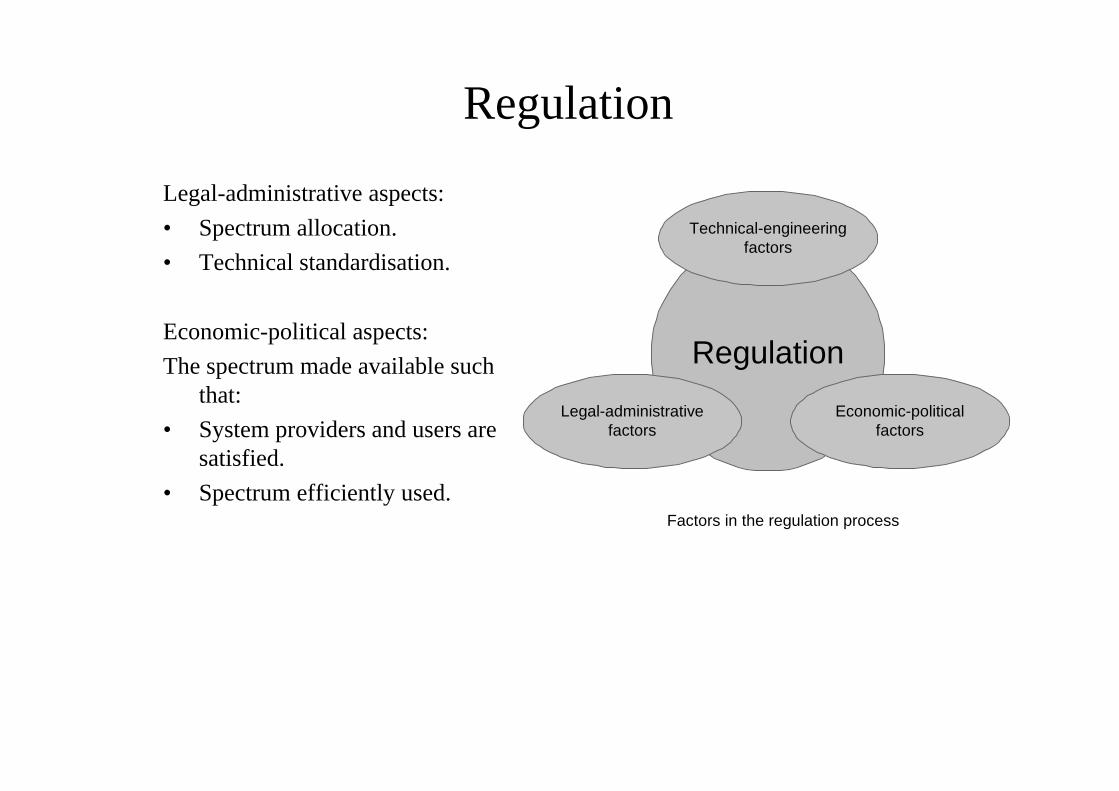
Regulation
Legal-administrative aspects:
• Spectrum allocation.
• Technical standardisation.
Economic-political aspects:
The spectrum made available suchthat:
• System providers and users aresatisfied.
• Spectrum efficiently used.
Regulation
Technical-engineeringfactors
Factors in the regulation process
Legal-administrativefactors
Economic-politicalfactors
Specification process for 3G
• In Europe 3G has become UMTS (Universal Mobile TelecommunicationSystem), following the ETSI perspective.
• In Japan and US IMT-2000 (International Mobile Telephony 2000). The namecomes from the International Telecommunication Union (ITU) developmentprojects.
• Evolution of IS-95 system is covered under the name CDMA2000.
• ITU FPLMTS project - promotion of common architectural principles amongthe family of IMT-2000 systems.
• Different short-term targets.– Europe: need for commercial mobile data service.
– Far East: need for additional spectrum for speech services.
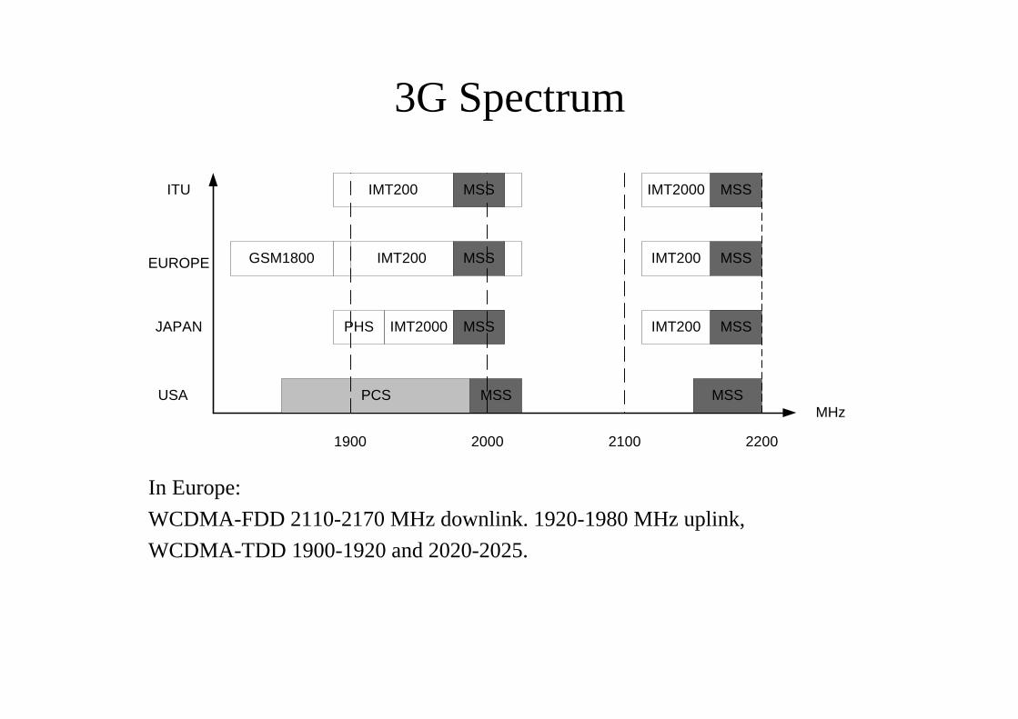
3G Spectrum
In Europe:
WCDMA-FDD 2110-2170 MHz downlink. 1920-1980 MHz uplink,
WCDMA-TDD 1900-1920 and 2020-2025.
PCS MSS
PHS IMT2000 MSS
GSM1800 IMT200 MSS
IMT200 MSS IMT2000
IMT200
IMT200 MSS
MSS
MSS
MSS
1900 2000 2100 2200
USA
JAPAN
EUROPE
ITU
MHz
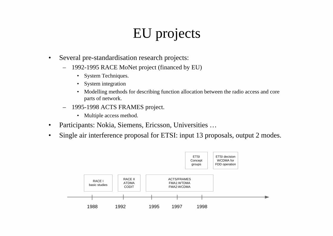
EU projects
• Several pre-standardisation research projects:– 1992-1995 RACE MoNet project (financed by EU)
• System Techniques.
• System integration
• Modelling methods for describing function allocation between the radio access and coreparts of network.
– 1995-1998 ACTS FRAMES project.• Multiple access method.
• Participants: Nokia, Siemens, Ericsson, Universities …
• Single air interference proposal for ETSI: input 13 proposals, output 2 modes.
RACE Ibasic studies
RACE IIATDMACODIT
ACTS/FRAMESFMA1:WTDMAFMA2:WCDMA
ETSIConceptgroups
ETSI decisionWCDMA for
FDD operation
1988 1992 1995 1997 1998
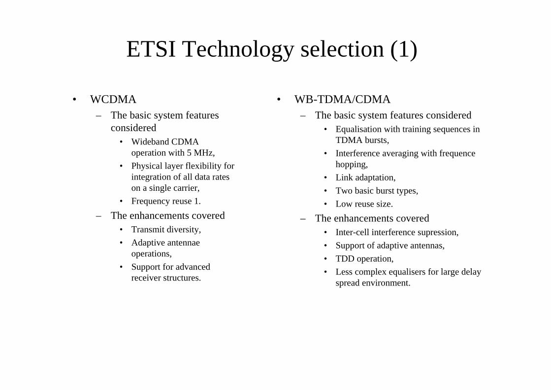
ETSI Technology selection (1)
• WCDMA– The basic system features
considered• Wideband CDMA
operation with 5 MHz,
• Physical layer flexibility forintegration of all data rateson a single carrier,
• Frequency reuse 1.
– The enhancements covered• Transmit diversity,
• Adaptive antennaeoperations,
• Support for advancedreceiver structures.
• WB-TDMA/CDMA– The basic system features considered
• Equalisation with training sequences inTDMA bursts,
• Interference averaging with frequencehopping,
• Link adaptation,
• Two basic burst types,
• Low reuse size.
– The enhancements covered• Inter-cell interference supression,
• Support of adaptive antennas,
• TDD operation,
• Less complex equalisers for large delayspread environment.
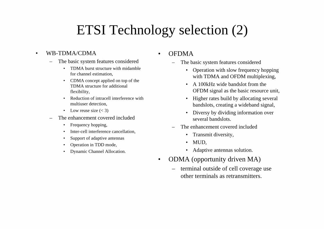
ETSI Technology selection (2)
• WB-TDMA/CDMA– The basic system features considered
• TDMA burst structure with midamblefor channel estimation,
• CDMA concept applied on top of theTDMA structure for additionalflexibility,
• Reduction of intracell interference withmultiuser detection,
• Low reuse size (< 3)
– The enhancement covered included• Frequency hopping,
• Inter-cell interference cancellation,
• Support of adaptive antennas
• Operation in TDD mode,
• Dynamic Channel Allocation.
• OFDMA– The basic system features considered
• Operation with slow frequency hoppingwith TDMA and OFDM multiplexing,
• A 100kHz wide bandslot from theOFDM signal as the basic resource unit,
• Higher rates build by allocating severalbandslots, creating a wideband signal,
• Diversy by dividing information overseveral bandslots.
– The enhancement covered included
• Transmit diversity,
• MUD,
• Adaptive antennas solution.
• ODMA (opportunity driven MA)– terminal outside of cell coverage use
other terminals as retransmitters.
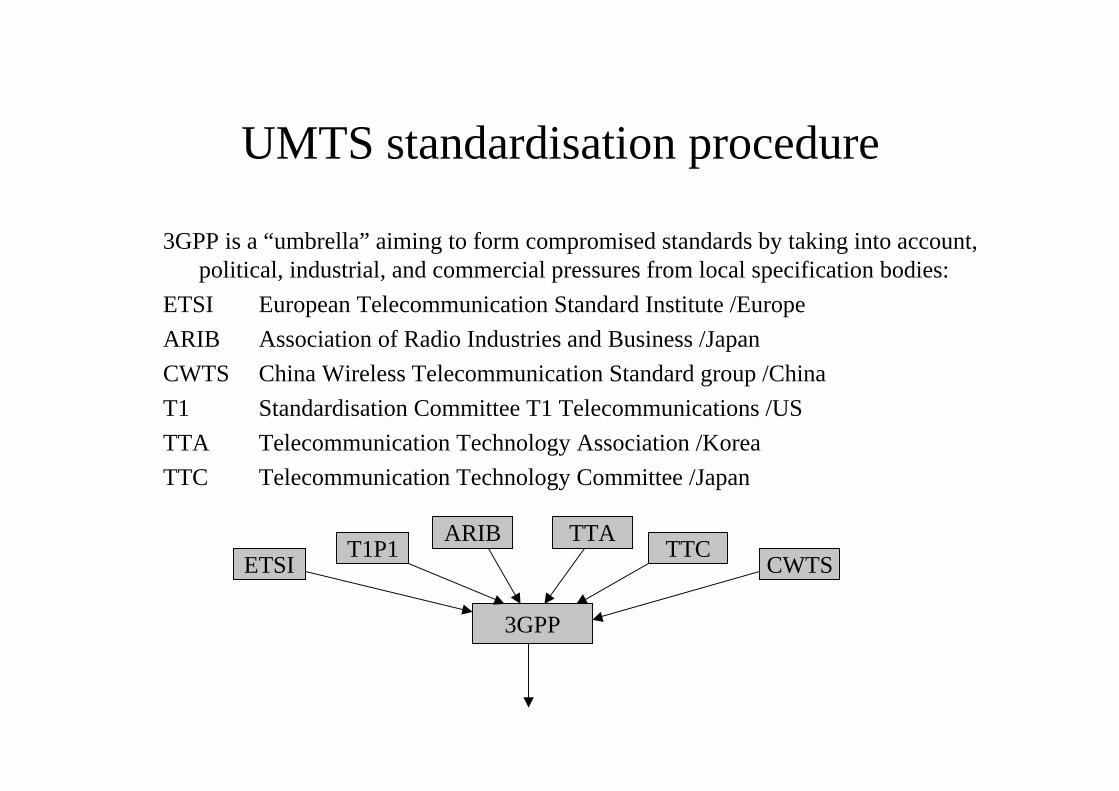
UMTS standardisation procedure
3GPP is a “umbrella” aiming to form compromised standards by taking into account,political, industrial, and commercial pressures from local specification bodies:
ETSI European Telecommunication Standard Institute /Europe
ARIB Association of Radio Industries and Business /Japan
CWTS China Wireless Telecommunication Standard group /China
T1 Standardisation Committee T1 Telecommunications /US
TTA Telecommunication Technology Association /Korea
TTC Telecommunication Technology Committee /Japan
3GPP
ETSIARIB TTA
T1P1 TTCCWTS
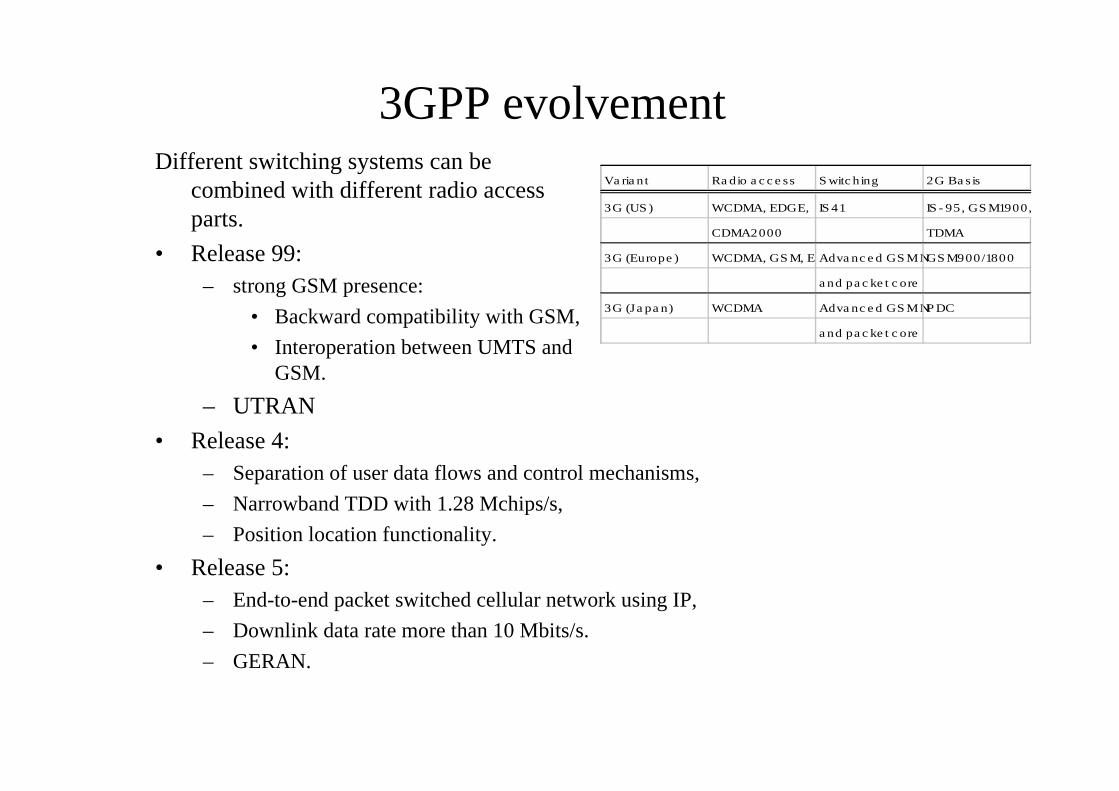
3GPP evolvement
• Release 4:– Separation of user data flows and control mechanisms,
– Narrowband TDD with 1.28 Mchips/s,
– Position location functionality.
• Release 5:– End-to-end packet switched cellular network using IP,
– Downlink data rate more than 10 Mbits/s.
– GERAN.
Va ria nt Ra dio a c c e ss S witc hing 2G Ba s is
3G (US ) WCDMA, EDGE, IS 41 IS - 95, GS M1900,
CDMA2000 TDMA
3G (Europe ) WCDMA, GS M, EDAdva nc e d GS M NGS M900/1800
a nd pa c ke t c ore
3G (Ja pa n) WCDMA Adva nc e d GS M NP DC
a nd pa c ke t c ore
Different switching systems can becombined with different radio accessparts.
• Release 99:– strong GSM presence:
• Backward compatibility with GSM,
• Interoperation between UMTS andGSM.
– UTRAN
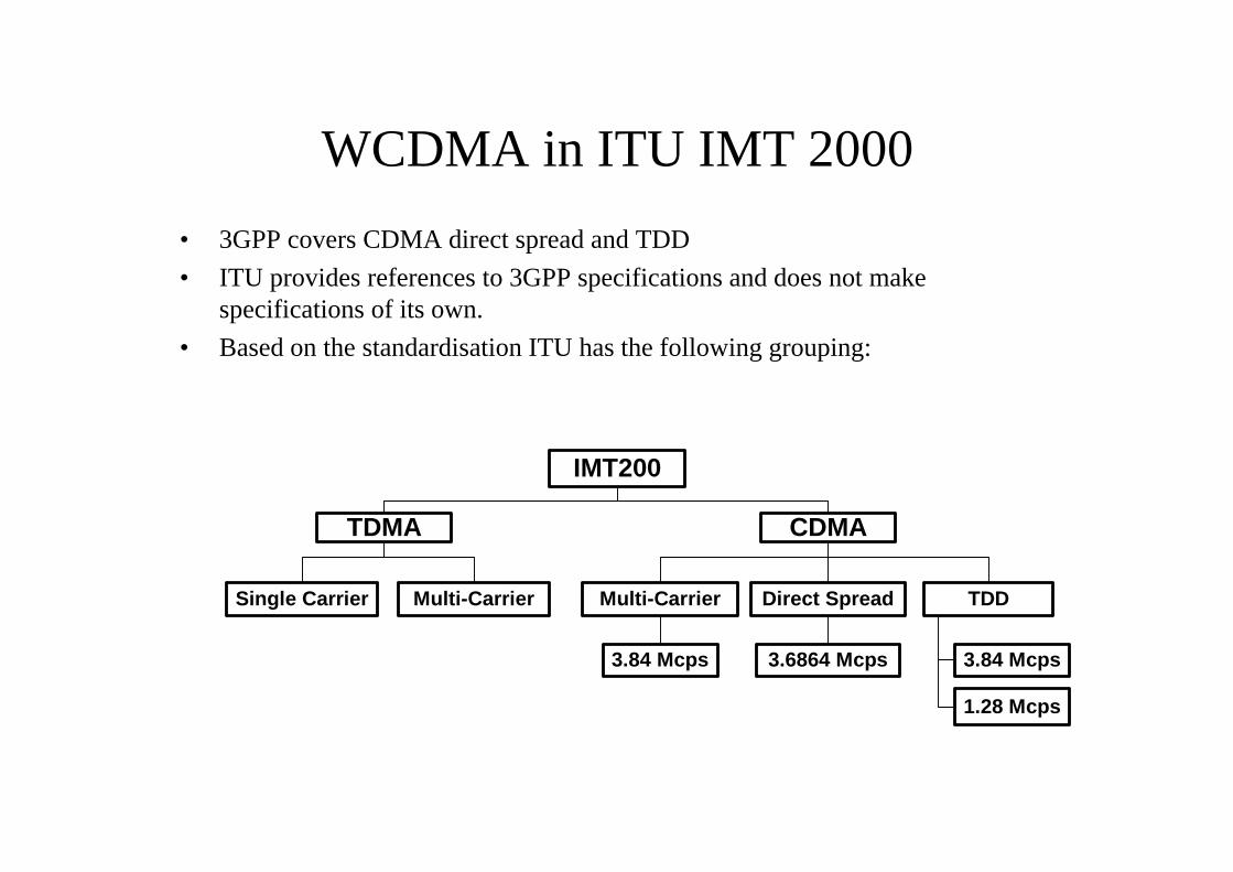
WCDMA in ITU IMT 2000
• 3GPP covers CDMA direct spread and TDD
• ITU provides references to 3GPP specifications and does not makespecifications of its own.
• Based on the standardisation ITU has the following grouping:
IMT200
TDMA CDMA
Single Carrier Multi-Carrier Direct SpreadMulti-Carrier TDD
3.84 Mcps 3.6864 Mcps 3.84 Mcps
1.28 Mcps
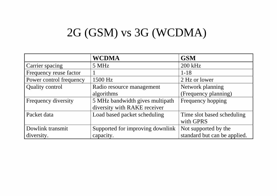
2G (GSM) vs 3G (WCDMA)
WCDMA GSMCarrier spacing 5 MHz 200 kHzFrequency reuse factor 1 1-18Power control frequency 1500 Hz 2 Hz or lowerQuality control Radio resource management
algorithmsNetwork planning(Frequency planning)
Frequency diversity 5 MHz bandwidth gives multipathdiversity with RAKE receiver
Frequency hopping
Packet data Load based packet scheduling Time slot based schedulingwith GPRS
Dowlink transmitdiversity.
Supported for improving downlinkcapacity.
Not supported by thestandard but can be applied.


