MA2-3 Frequency C oordination Between CDMA and Non-CDMA Systems Samir Soliman and Chuck Wheatley QUALCOMM Incorporated 6455 Lusk Boulevard San Diego, CA 92121 Abstract-Mutual interference between non- CDMA (FM and TDM A) subscri ber stati ons (SS) and CDMA base stations (BS), as well as interference between CDMA SS and non-CDMA BS are investigated. The noise figure is used as a measure of degradation of the receiver performance. It is shown that at a frequency offset of more than 870 kHz, the non-CDMA SS will not cause any degradation to the CDMA B S. Conversely, the CDMA BS will degrade the noise figure of the non-CDMA S S . It is also shown that a space separation (guard zone) of 14 4 dB path loss or more is sufficient in cases where the CDMA system shares the frequency band with the non- CDMA system. This can be achieved by having one tier of cells, operating at a different frequency, separating the two systems. The effect of a CDMA S S on an FM BS depends on the size of t he CDM A BS. For large cells, the CDM A SS is required to transmit at full power with noticeable sidebands and will cause more degradation to the FM B S before the FM BS can degrade the CDMA SS noise figure. For medium size cells, the CDMA S S is not required to transmit at full power (hence, having much lower sidebands). In this case the FM B S will be able to tolerate the CDMA SS . Meanwhile, the CDMA SS will suffer degradation as it is moved closer to the FM BS. For small cells, the CDMA S S will transmit at much less than full power and will have no effect at all on the FM B S, even if moved very close to the FM BS . 1. INTRODUCTION Frequency coordination is the process of assigning frequency bands to neighboring or coexisting systems to minimize interference effects. This interference is characterized by unwanted signals from other frequency channels "spilling over" or injecting energy into the desired channel. The unwanted interference can be classified as either "in-band" or "out-of-band". The primary design objective of any commercial mobile radio system is to conserve the available spectrum by reusing frequency channels in the adjacent areas, provided that some frequency coordination can be exercised. This allows the CDMA system to be phased into operation in a given geographical area without immediately obsoleting existing equipment operating in the same band. It is even possible that the CDMA and the FM systems can coexist permanentl y, using the same band. The objective of this paper is to provide insight into the frequency coordination issue of CDMA cellular site engineering and network planning. We shall also introduce new terms such as guard bands and guard zones and provide useful tools to calculate them. We wish to state at the outset that these tools contain simplifying assumptions made for the sake of analytical tractability. Nevertheless, the results obtained can be viewed as building blocks that can be assembled by network planners (designers) and applied to more sophisticated scenarios of network architecture. In practice, frequen cy coordination is a complex task that must take into account the detailed terrain of the area in question. Computer analysis is extensively used to help in such tasks. Section 2 presents masks for both transmitter and receiver characteristics. Section 3 quantitatively assesses the level of mutual interference between CDMA base stations and FM (TDMA) subscriber stations. 79 TH0661-9195/0000-0079$01 OO 0 995 IEEE MTT-S 1995 International Topical Symposium Authorized licensed use limited to: Vel Techn. Down loaded on July 09,2010 at 01:57:28 UTC from IEEE Xplore. Restrictions apply.
Transcript
8/8/2019 Frequency Coordination Between Cdma and Non Cdma Systems
Frequency Coordination Between CDMA and Non-CDMA Systems
Samir Sol iman and Ch uck Wheat leyQUA LCO MM Incorpora ted
6455 Lusk BoulevardSan Diego, CA 92121
Abstract-Mutual interferen ce between non-CDMA (FM and TDM A) subscriber stations(SS)and CDMA base s ta t ions (BS), as well asinterference between C DM ASS and non-CDMABS are investigated.
The noise figure is used as a measure ofdegradation of the receiver performance. It isshown that at a frequency offset of more than870 kHz, the non-CDMA SS will not cause anydegradation to the CDMA BS. Conversely, theCDMA BS will degrade the noise figure of thenon-CDMA S S. It is also shown that a spaceseparation (guard zone) of 14 4 dB path loss ormore is sufficient in cases where the CDMAsystem shares the frequency band with the non-CDM A system. This can be achieved by havingone tier of cells, operating at a differentfrequency, separating the two systems.
The effect of a CDMA SS on an FM BSdepends on the size of the CDM A BS. For largecells, the CDM A SS is required to transmit at fullpower with noticeable sidebands and will causemore degradation to the FM BS before the FMBS can degrade the CDM ASS noise figure.
For medium size cells, the CDMASS is notrequired to transmit at full power (hence, havingmuch lower sidebands). In this case theFM BSwil l be able to tolerate the CDMA S S .Meanwhi le , the CDMA SS wil l sufferdegradation as it is moved closer to the FM BS.
For small cells, the CDMA SS will transmitat much less than full power and will have no
effect at all on the FM BS, even if moved veryclose to the FM BS.
1. INTRODUCTION
Frequency coordination is the process ofassigning frequency bands to neighboring or
coexisting s ystem s to minimize interferen ceeffects. This interference is characterized byunwanted signals from other frequency channels"spilling over" or injecting energy into the desiredchannel. Th e unwanted interference can be
classified as either "in-band" or "out-of-band".The pr imary design object ive of any
commercial mobile radio system is to conservethe available spectrum by reusing frequencychannels in the adjacent areas, provided that somefrequency coordination can be exercised. Thisallows the CDMA system to be phased intooperation in a given geographical area withoutimmediate ly obsolet ing exis t ing equipmentoperating in the same band. It is even possiblethat the CDMA and the FM systems can coexistpermanently, using the same band.
The objective of this paper is to provideinsight into the frequency coordination issue ofCDMA cellular site engineering and networkplanning. W e shall also introduce new terms suchas guard bands and guard zones and provideuseful tools to calculate them. W e wish to state atthe outset that these tools contain simplifyingassumptions made for the sake of analyticaltractability. Nevertheless, the results obtainedcan be viewed as building blocks that can beassembled by network planners (designers) andapplied to more sophisticated scenarios ofnetwork architecture. In practice, frequen cycoordination is a complex task that must take intoaccount the detailed terrain of the area inquestion. Com puter analysisis extensively usedto help in such tasks.
Section 2 presents masks for both transmitterand receiver character is tics . Sect ion 3quantitatively assesses the level of mutualinterference between CDMA base stations andFM (TDMA) subscriber stations.
79
TH0661-9195/0000-0079$01 OO 0 995 IEEE MTT-S 1995 International Topical Symposium
Authorized licensed use limited to: Vel Techn. Downloaded on July 09,2010 at 01:57:28 UTC from IEEE Xplore. Restrictions apply.
8/8/2019 Frequency Coordination Between Cdma and Non Cdma Systems
Sect ion 4 treats the mutual interferencebetween CDMA subscriber stations and FM(TD MA ) base stations. The treatment is based onthe average values of the system parameterswithout paying too much attenuationto the exact
statistical distribution . The objective is to providethe system engineer with simple tools to helpeff ic ient ly budget for di fferent types ofinterference and channel impairment. W e willlump the propagation loss and the fading effect inone parameter called the path loss, expressed indB , rather than absolute distance. The systemdesigner can then use the best server (coverage)maps to determine the actual distance for aparticular cell site.
2. TRANSMITTERAND RECEIVERCHARACTERISTICS
Receivers on a given channel can tolerateonly a certain level of adjacent channel signal atthe input without suffering significant degradationin perform ance[l] . The proximity in frequency(guard band) and space (guard zone) with whichCD MA channels and non-CDMA can be locatedis determined by many parameters. Among thoseparameters are the network architecture, thereceiver's filter characteristics, and the path loss.The network architecture (macro vs. micro) willdetermine the cell size, the power levels of theinterfering signals, the reuse factor, etc., while thepath loss will depend on the environment inwhich the system is deployed (e.g., open vs.
suburban area propagation models), antennaheight and fading characteristics. Transmitter andreceiver characteristics are component designissues; they will determine the amount ofinterference passed by the receiver's filters. Byconsidering masks for both theSS transmitter andthe BS receiver frequency characteristics, we canobtain an estimate of the amount of mutualinterference between CDMA and non-CDMAsystems.
2.1 Transmitters
For th e CDMA system defined in theTIA/EIA/IS-95 E2]- the transmit spectrum isinitially determined by the FIR filters at thebaseband, then translated and amplified to thedesired UH F band and power level. In thisprocess, nonlinear effects in the amplifiersgenerate inter-modulation products which showup as a noise floor surrounding the desired, nearlyideal spectrum . With a good transmitter design,
almost all of this distortion occurs in the finalpower amplifier stage of the radio. Th e thirdorder non-linearity will cause almost parabolicshaped sidebands (convolving three rectangularshaped spectra will result in an approximately
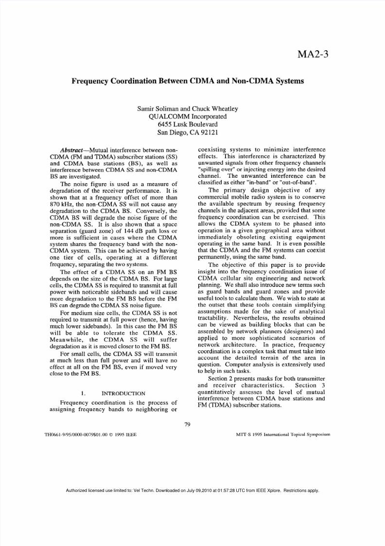
Gaussian shaped curve on a linear scale and aparabolic shape on a dB scale). A similarargument can be applied to the fifth order non-linearity. Figure I illustrates the mask ofmeasured performance of a typical ABSS poweramplifier operating approximately 2 dB short ofit's 1 dB compression point transmitting fullpower. Within 2 MH z of the center frequency allinterference results from 3rd order distortion inthe final amplifier. At lower transmit powers theabsolute noise floor at 75 0 kHz offset wi l ldecrease approximately 3 dB for every 1 dB oftransmit powe r reduction. Outside the 2 M H zrange, the interference is du e to the 5th o rder non-linearity. Cons equently, its level will decrease5 dB for every 1 dB of power in the main lobe.Figure 2 illustrates the BS transm itter. It is verysimilar to the SS transmit characteristics, exceptthat it has better sidebands.
5
02!; 5:: - 1 0
Q) - 1 5U2 - 2 0
c - 2 5
- 3 0- 3 5
- 4 0
c..-ul
0 0 0 0 0 0 0 0 0 0 0 0 0 0 0
0 0 0 0 0 0 0 0 0 0 0 0 0 0
- - c O m o ( u m ) ( ~ c ) c ) ( D o ) c U I I ) C O -. - - - c y
Frequency (kHz)
? : - - ' I
"
Figure 1 . Subscriber Station Transmit Ma sk
80
Authorized licensed use limited to: Vel Techn. Downloaded on July 09,2010 at 01:57:28 UTC from IEEE Xplore. Restrictions apply.
8/8/2019 Frequency Coordination Between Cdma and Non Cdma Systems
signal can be degraded by interference:There are three distinct ways that th e received
(1) Interference that makes its way into theanalog-to-digital converters (ADC) of thereceiver. This is reduced by increasedfilter selectivity anywhere in the receiverchannel.
(2) Interference which enters theAGC path,but is rejected prior to the ADC. Thisform of interference, if it is slowlyvarying, will not cau se significant lossesas the radio will adapt by changing its
operating point.(3) Interference that is so large as to causeone or more gain stages of the receiver togo nonlinear before the interference canbe removed by filtering. This effect isreduced by providing high dynamic rangeelements in the receiver, especially in theearlier stages. Clearly this is more easilyaccomplished in a base station thanin asubscriber unit.
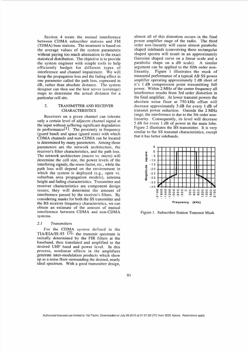
For SS to BS links, frequency coordinationlimits are based on the selectivity that can berealistically provided in a very good BS receiverdesign. Specifically, this design assumesa tripleconversion receiver (UHF to analog basebandprior to the ADC) using state of the art SAWfilters at the first IF stage. The se filters canprov ide very low distortion filtering but not close-in interference rejection. This is followedat thesecond IF stage where a significant amount ofclose-in rejection can be realized with relatively
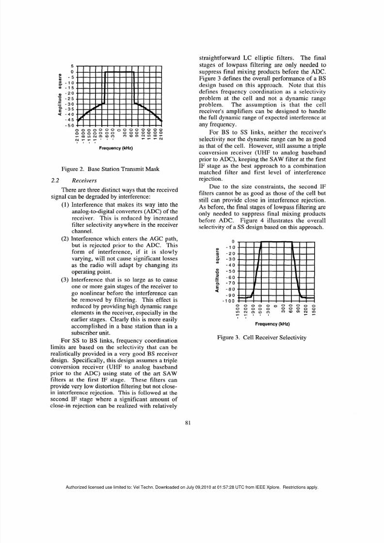
straightforward L e elliptic filters. The finalstages of lowpass filtering are only needed tosuppress final mixing products before the ADC.Figure 3 defines the overall performance of a BSdesign based on this approa ch. Note that thisdefines frequency coordination as a selectivityproblem at the cell and not a dynamic rangeproblem . Th e assump tion is that the cellreceiver's amplifiers can be designed to handlethe full dynamic rangeof expected interference atany frequency.
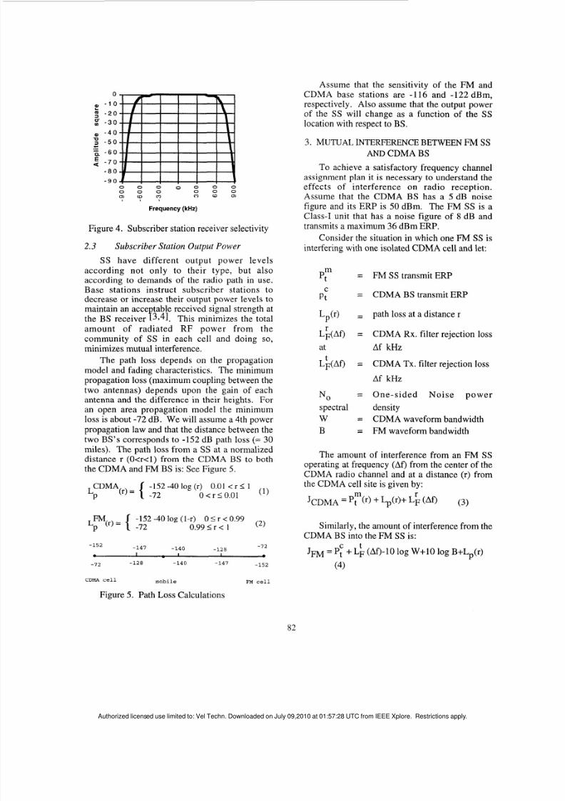
For BS to SS links, neither the receiver'sselectivity nor the dynamic range can be as go odas that of the cell. How ever, still assu me a tripleconversion receiver (UHF to analog basebandprior to ADC ), keeping the SA W filter at the firstIF stage as the best approach to a combinationmatched filter and first level of interferencerejection.
Due to the size constraints, the second IFfilters cannot be as good as those of the cell butstill can provide close in interference rejection.As before, the final stages of lowpass filtering areonly needed to suppress final mixing productsbefore ADC. Figure 4 llustrates the overallselectivity of a SS design based o n this approach.
0 0 0 0 0 0 0 0 0 0 00 0 0 0 0 0 0 0 0 0
Z z y y ? m w " a7 -
I ,
Frequency (kHz)
Figure 3. Cell Receiver Selectivity
81
Authorized licensed use limited to: Vel Techn. Downloaded on July 09,2010 at 01:57:28 UTC from IEEE Xplore. Restrictions apply.
8/8/2019 Frequency Coordination Between Cdma and Non Cdma Systems
according not only to thei r type, but a lsoaccording to demands of the radio path in use.Base stations instruct subscriber stations todecrease or increase their output power levelstomaintain an acce table received signal strength atth e BS receiver f3741. This minim izes the totala m o u n t of r ad ia ted R F power f rom thecommunity of SS in each cell and doing so,minimizes mutual interference.
The path loss depends on the propagationmodel and fading characteristics. The minimumpropagation loss (maximum coupling between thetwo antennas) depends upon the gain of eachanten na and the difference in their heights. Foran open area propagation model the minimumloss is about -72 dB. W e will assume a 4th powerpropagation law and that the distance between thetwo B S's corresponds to -152 dB pathloss (= 30miles). Th e path loss f rom a SS at a normalizeddistance r ( O a c l ) from the CDMA BS to boththe CDM A and FM BS is: SeeFigure 5.
(1 )LCDMA -152 -40 og (r) 0.01 < r S 1
P ( r )= { -72 0 < r I O . 0 1
( 2 )-152 -40 log (1-r) 0 5 r < 0.99
~ ~ ( r ) ={ -72 0.99 5 r < 1
- 7 2-147 -140 -128
-152
e I I I--15272 -128 -140 -147
Assume that the sensitivity of the FM andCDMA base stations are -1 16 and -122 dBm,respectively. Also assume that the output powerof the SS will change as a function of theSSlocation with respect toBS.
3. MUTUAL INTERFERENCE BETWEEN FM SSAND CDMA BS
To achieve a satisfactory frequency channelassignment plan it is necessary to understand theeffects of in terference on radio recept ion.Assume that the CDMA BS has a5 dB noisefigure and its ERP is 50 dBm. The FM SS is aClass-I unit that has a noise figure of8 dB andtransmits a maximum 36 dBm ERP.
Consider the situation in which oneFM S isinterfering with one isolated C DM A cell and let:
pt" = FM S transmit ER P
= C D M A BS transmit ER Pp:
Lp(r) = path loss at a distance r
L ~ ( A Q = CDMA RX . filter rejection loss
at Af kH z
L;(M = CDMA TX. filter rejection loss
Af kH z
N O = O n e - s i d e d N o i s e p o w e r
spectral densityW = CDMA waveform bandwidthB = FM waveform bandwidth
The amount of interference from anFM SSoperating at frequency (Af) from the center of theCDMA radio channel and at a distance (r) fromthe CDM A cell site is givenby :
Similarly, the amount of interference from theCDM A BS into theFM SS is:
tJm = Pf +LF (Af)-10 log W+10 log B+Lp(r)
(4)
mobile FM cellDMA cell
Figure 5. Path Loss Calculations
Authorized licensed use limited to: Vel Techn. Downloaded on July 09,2010 at 01:57:28 UTC from IEEE Xplore. Restrictions apply.
8/8/2019 Frequency Coordination Between Cdma and Non Cdma Systems
The noise figure is a good measure of thedegradation in the performance of a specificreceiver that is subjected to interference. Th ecorresponding noise figures are:
I
( 5 )J ~ ~ ~ ~
FCDMA = F~~~~ i-
NOW
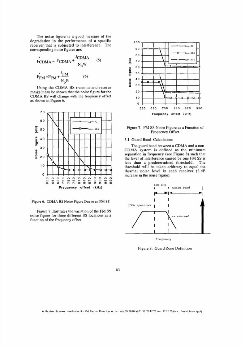
Using the CDMA BS transmit and receivemasks it can be sho wn that the noise figure for theCDMA BS will change with the frequency offsetas shown in Figure 6.
70
6 0
A
E 5 0v
0)U).-g 20
1 0
00 0 0 0 0 0 0 0 0 0 0 0 0
O m c n " c a r b t - O C 9 a c nm w w b b b o 3 c a c a m c n c n f n
Frequency off se t (kHz)
Figure 6. CDMA BS Noise Figure Due to an FM S
Figure 7 illustrates the variation of the F MSSnoise figure for three differentSS locations as afunction of the frequency offset.
1 0 0
9 0
8 0
7 0
6 022 50
CII 4 0
30
20
1 0
0
-Lp=-128
- -p= - 11
Y
c
.-
6 3 0 6 9 0 7 5 0 8 1 0 8 7 0 9 3 0
Frequency offset ( k H z )
Figure 7. FM SS Noise Figure as a Function ofFrequency Offset
3.1 Guard Band Calculations
The guard band betweena CDMA and a non-CDMA system is defined as the minimumseparation in frequency (see Figure8) such thatthe level of interference caused by oneFM S S isless than a predetermined threshold. Thethreshold will be taken arbitrary to equal thethermal noise level in each receiver ( 3 dB
increase in the noise figure).
6 30 kHzI IGuard band
-
Frequency
Figure 8. Guard Zone Definition
83
Authorized licensed use limited to: Vel Techn. Downloaded on July 09,2010 at 01:57:28 UTC from IEEE Xplore. Restrictions apply.
8/8/2019 Frequency Coordination Between Cdma and Non Cdma Systems
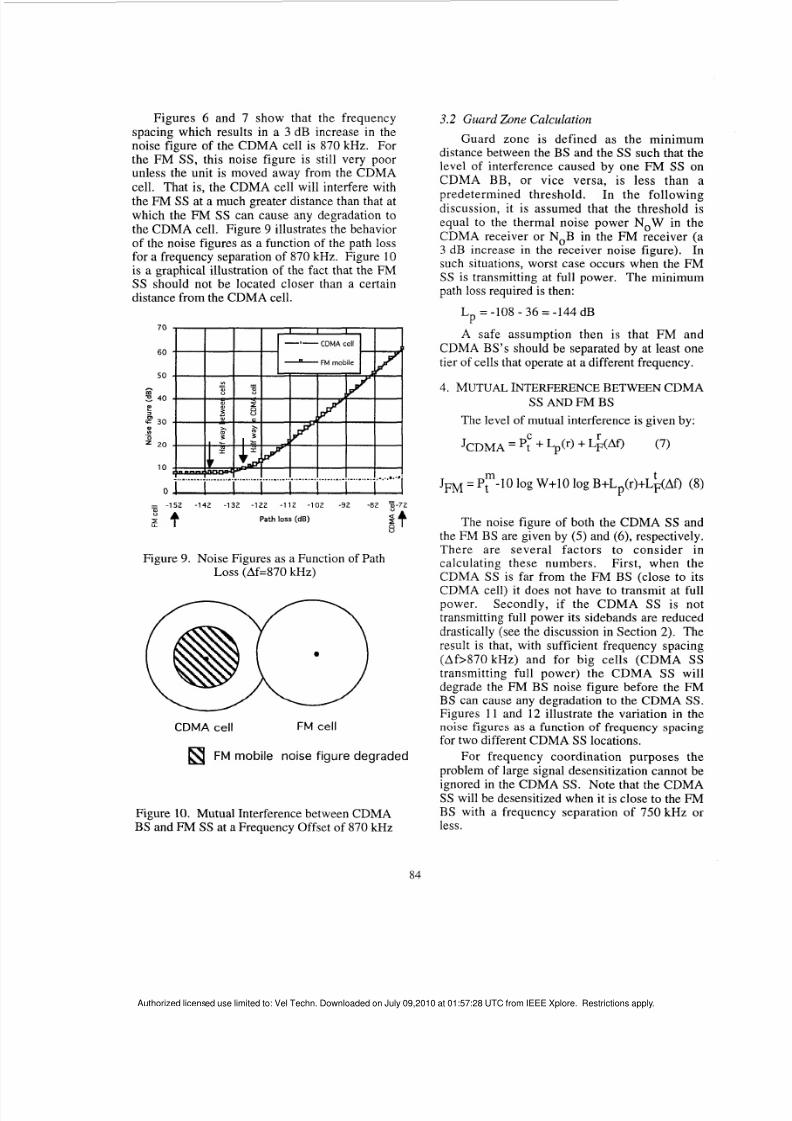
Figures 6 an d 7 show that the frequencyspacing which results in a3 dB increase in thenoise figure of the CD MA cell is 870 kHz. Forthe FM SS, this noise figure is still very poorunless the unit is moved away from the CDMA
cell. That is, the CD M A cell will interfere withth e FM SS at a much greater distance than that atwhich the FM SS can cause any degradation tothe CDMA cell. Figure 9 illustrates the beha viorof the noise figures as a function of the pathlossfor a frequency separation of 870 kHz.Figure 10 is a graphical illustration of the fact that the FMSS should not be located closer than a certaindistance from the CDM A cell.
Figure 9. Noise Figures asa Function of PathLOSS Af=870 kHz)
CDMA cell FM cell
FM mobile noise figure degraded
Figure 10. Mutual Interference between CDM ABS and FM S at a Frequency Offset of 870 kHz
3.2 Guard Zone Calculation
Guard zone is def ined as the minimumdistance between theBS and the SS such that thelevel of interference caused by oneFM SS onCDMA BB, o r v ice ve r sa , is less than apredetermined threshold. In the fol lowingdiscussion, it is assumed that the threshold isequal to the thermal noise power N O W in theCDM A receiver or NOB in the FM receiver (a3 dB increase in the receiver noise figure). Insuch situations, worst case occurs when the FMSS is transmitting at full power. The minimumpath loss required is then:
L = -108 - 36 = -144 dBP
A safe assumption then is that FM andCDMA BS's should be separated by at least onetier of cells that operate at a different frequenc y.
4. MUTUAL INTERFERENCE BETWEEN CDMASS AND FM BS
The level of mutual interference is given by:
m tJw= , -10 log W+10 log B+Lp(r)+LF(Af) (8)
The noise figure of both the CDMASS an dthe FM BS are givenby ( 5 ) and (6), respectively.There are several factors to consider in
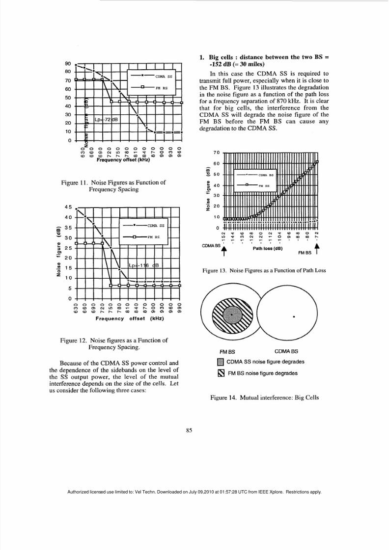
calculating these numb ers. First , when theCDMA SS is far from the FM BS (closeto itsCDMA cell) it does not have to transmit at fullpower. Secondly, i f the CD MA SS is nottransmitting full power its sidebands are reduceddrastically (see the discussion in Section2). Theresult is that, with sufficient frequency spacing(Af>870 kHz) and for b ig cel ls (CDM A SStransmit t ing ful l power) the CDMA SS willdegrade the FM BS noise figure before the FMBS can cause any degradation to the CDMASS.Figures 11 and 12 illustrate the variation in thenoise figures as a function of frequency spacingfor two different CDMASS locations.
For frequency coordination purposes theproblem of large signal desensitization cannot beignored in the CDMASS. Note that the CDM ASS will be desensitized w hen it is close to theFMBS with a frequency separation of 750 kHz o rless.
84
Authorized licensed use limited to: Vel Techn. Downloaded on July 09,2010 at 01:57:28 UTC from IEEE Xplore. Restrictions apply.
8/8/2019 Frequency Coordination Between Cdma and Non Cdma Systems
O u l m " a r * b O O u Ju l u l u l b b b a a a c n c n c n
Frequency offset kHz)
Figure 1
I .Noise Figures
asFunction of
Frequency Spacing
4 5
40
3 5
30
?3 2 5- 20
.Y 1 5
1 0
5
0
v
0.-0
0z
0 0 0 0 0 0 0 0 0 0 0 0 0
m u l u J " a - * b o o u l mW u l u J b b b a m a c n c n c n c n
Frequency offset (kHz)
Figure 12. Noise figures as a Fu nction ofFrequency Spacing.
Because of the CDMASS power control and
the dependence of the sidebands on the level ofth e SS output power, the level of the mutualinterference dependson the size of the cells. Letus consider the following three cases:
1. Big cells : distance between the two BS =-152 dB (= 30 miles)
In this case the CDMA SS is required totransmit full power, especially when it is close tothe FM BS. Figure 13 illustrates the d egradationin the noise figure as a function of the path lossfor a frequency separationof 870 kHz. It is clearthat for big cells, the interference from theC D M A SS will degrade the noise figure of theF M BS before the FM BS can cause anydegradation to theCDMA SS.
70
6 0m3 0
$ 4 0cn- 3 0
0 20z
1 0
0
.-
0
.-
t, , I , , ,
Path loss (dB)FM BS
Figure 13. Noise Figures as a Function of Path Loss
CDMA BSM BS
CDMASS noise figure degrad es
19 FM BS noise figure degrad es
Figure 14. Mutua l interference: Big Cells
85
Authorized licensed use limited to: Vel Techn. Downloaded on July 09,2010 at 01:57:28 UTC from IEEE Xplore. Restrictions apply.
8/8/2019 Frequency Coordination Between Cdma and Non Cdma Systems
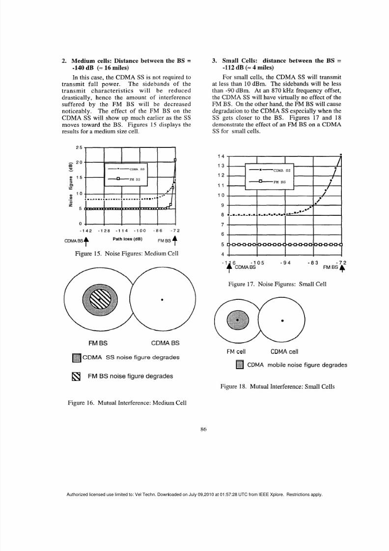
2. Medium cells: Distance between the BS =-140 dB (= 16 miles)
In this case, the CDMA SS is not required totransmit full power. The sidebands of the
transmit character is t ics wi l l be reduceddrastically, hence the amount of interferencesuffered by the FM BS will be decreasednoticeably. The effect of the FM BS on theCDMA SS will show up much earlier as theSSmoves toward the BS. Figures 15 displays theresults for a medium size cell.
2 5
- 0mUv
- BS1 5
0 '0
3
ol.-U-
.-0
25
0
- 1 4 2 - 1 2 0 - 1 1 4 - 1 0 0 - 8 6 - 7 2
CDMABSf Path loss (dB) FM BS
Figure 15. Noise Figures: Medium Cell
FM BS CDMABS
3. Small Cells: distance between the BS =-112 dB (= 4 miles)
For small cells, the CDMA SS will transmitat less than 10 dBm . The sidebands will be less
than -90 dBm. At an 87 0 kHz frequency offset,the CDMA SS will have virtually no effect of theFM BS. On the other hand, theFM BS w ill causedegradation to the CDM ASS especially when theSS gets closer to the BS. Figures 17 and 18demonstrate the effect of an FM BS on a CDMASS for small cells.
1 4
1 3
1 2
1 1
1 0
9
8
7
-CDMA SS
- BS
CDMA S S noise figure degrades
FM BS noise figure degrades
- 1 0 5 - 9 4 - 8 3 - 7 2FM BS 4
Figure 17. No ise Figures: Sma ll Cell
FM cell CDMAcell
CDMA mobile noise figure degrades
Figure 18. Mutual Interference: Small Cells
Figure 16. Mutual Interference: Medium Cell
86
Authorized licensed use limited to: Vel Techn. Downloaded on July 09,2010 at 01:57:28 UTC from IEEE Xplore. Restrictions apply.
8/8/2019 Frequency Coordination Between Cdma and Non Cdma Systems
4.1 Guard Zone CalculationsFollowing th e argument of Section 3, th e
frequency offset between a CDMA SS and an €34BS should be greater than 870 kHz.
4.2 Guard Zone Calculations
between a CDMA SS and an in-band FM S is:From (7 ) and (8), the minimum path loss
Lmin = -105 - 36 = -141 dB
Again, a space separation of one celloperating at a different frequency between the FMand CDMA cells should be enough to provide theneeded isolation.
REFERENCESU.L. Rohde and T.T.N Bucher, CommunicationsReceivers: Principles and Design, McGraw Hill,1988.
TIA/EIA Interim Standard: Mobile Station-BaseStation Compatibility Standard for Dual-ModeWideband Spread Spectrum Cellular System ,July, 1993.S . Soliman, C. Wheatley, R. Padovani, "CDMAReverse Link Open Loop Power Control," Proc.of IEEE Globecom'92, Orlando, FL, Dec. 6-9,1992.Samir Soliman, "Closed Loop Power ControlFeedback Model," Qualcomm Internal memo.
Dr. Soliman has published more than 35 technicalarticles and is the principal author of the book,Continuous and Discrete Signals and Systems(Prentice-Hall, 1990). He is a member of Sigma Xi andEta Kappa Nu.
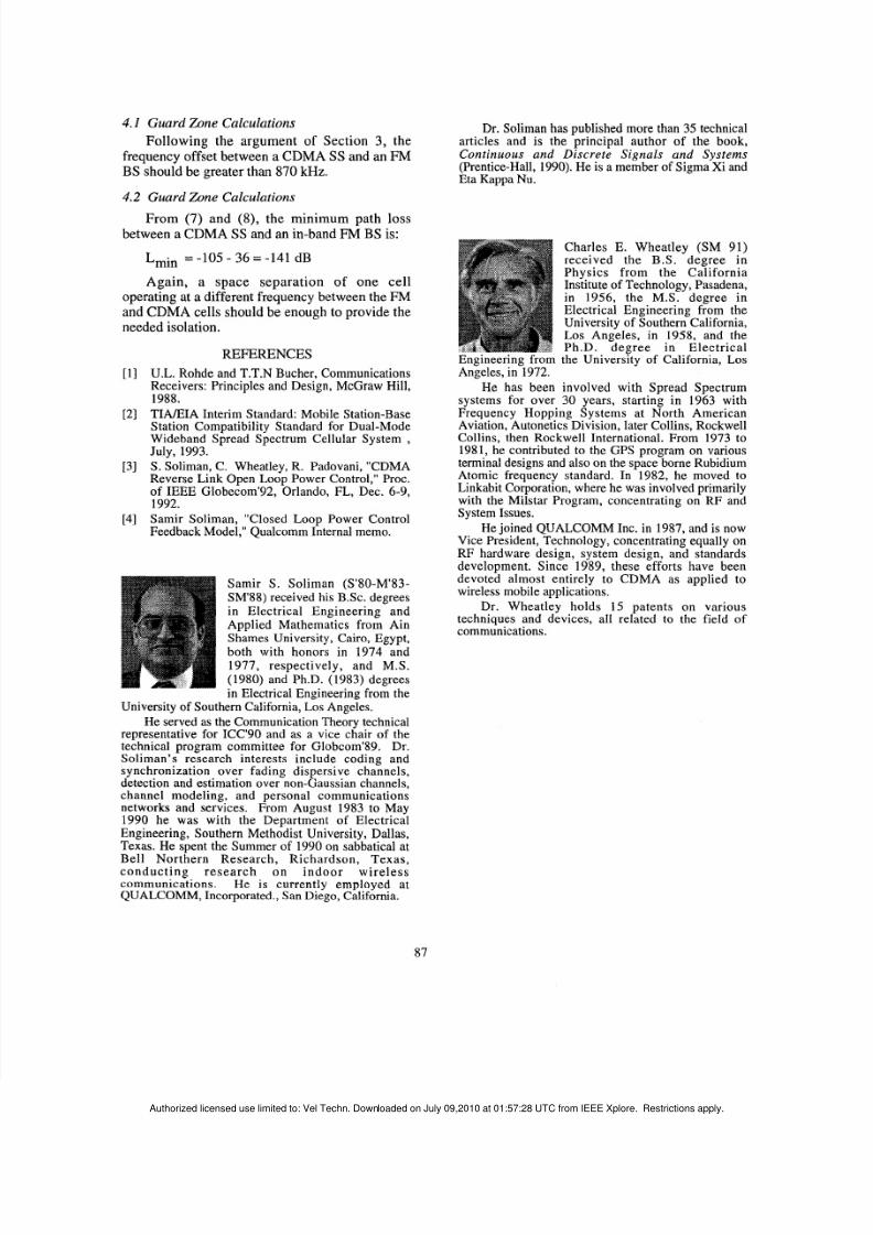
Charles E. Wheatley (SM 91)received the B.S. degree inPhysics from the CaliforniaInstitute of Technology, Pasadena,in 1956, the M.S. degree inElectrical Engineering from theUniversity of Southern California,Los Angeles, in 1958, and thePh.D. degree in Electrical
Engineering from the University of California, LosAngeles, in 1972.
He has been involved with Spread Spectrumsystems for over 30 years, starting in 1963 with
Frequency Hopping Systems at North AmericanAviation, Autonetics Division, later Collins, RockwellCollins, then Rockwell International. From 1973 to1981, he contributed to the GPS program on variousterminal designs and also on the space borne RubidiumAtomic frequency standard. In 1982, he moved toLinkabit Corporation, where he was involved primarilywith the Milstar Program, concentrating on RF andSystem Issues.
He joined QUALCOMM Inc. in 1987, and is nowVice President, Technology, concentrating equally onRF hardware design, system design, and standardsdevelopment. Since 1989, these efforts have been
Samir S . Soliman (S'80-M'83-SM'88) received his B.Sc. degreesin Electrical Engineering andApplied Mathematics from AinShames University, Cairo, Egypt,both with honors in 1974 and1977, respectively, and M.S.(1980) and Ph.D. (1983) degreesin Electrical Engineering from the
University of Southern California, Los Angeles.He served as the Communication Theory technical
representative for ICC'90 and as a vice chair of thetechnical program committee for Globcom'89. Dr.Soliman's research interests include coding andsynchronization over fading dispersive channels,detection and estimation over non-Gaussian channels,channel modeling, and personal communicationsnetworks and services. From August 1983 to May1990 he wa s with the Department of ElectricalEngineering, Southern Methodist University, Dallas,Texas. He spent the Summer of 1990 on sabbatical atBell Northern Research, Richardson, Texas,conducting research on indoor wirelesscommunications. He is currently employed atQUALCOMM, Incorporated., San Diego, California.
devoteh almost entirely to CDMA as applied towireless mobile applications.
Dr. Wheatley holds 15 patents on various
techniques and devices, all related to the field ofcommunications.