1 SECED Newsletter Vol. 21 No. 4 October 2009 ISSN 0967-859X THE SOCIETY FOR EARTHQUAKE AND CIVIL ENGINEERING DYNAMICS NEWSLETTER Volume 21 No 4 October 2009 S E SECED E D Seismic shift for SECED? In this issue Seismic shift for SECED? 1 Seismic earth pressures – a tech- nical note 4 New books 14 Notable Earthquakes January – June 2009 16 Forthcoming events 18 Letters 20 Ian G Smith Chairman Ian G Smith, Chairman of SECED, introduces an open letter to the ICE Director of Engineering Policy concerning the future of SECED. Dear Member, I hope you are enjoying our popular Newsletter and I write briefly just to draw your attention to a potential problem that seems to be looming concerning a part of the future funding of SECED. e letter on the following two pages to the Director of Engineering Policy and Innovation at the Institution of Civil Engineers (ICE) is self-explanatory and I hope that he will be able to convince ICE Council of the need to maintain ICE’s support to SECED at least at its current level. Other ICE Associated Societies have similar funding problems. I remain hopeful that this matter will be resolved but we are continuing to make plans for re- ducing key items of our current expenditure; the principal item being the ICE services we pay for. is may result in us looking for alternative meeting venues as we move into Spring meet- ings next year. Assuring you of our best endeavours and that we’ll keep you briefed on any key developments, as necessary.
Transcript
1SECED Newsletter Vol. 21 No. 4 October 2009
ISSN 0967-859XTHE SOCIETY FOR EARTHQUAKE AND
CIVIL ENGINEERING DYNAMICS
NEWSLETTERVolume 21 No 4
October 2009
SE
S E C E DED
Seismic shift for SECED?
In this issue
Seismic shift for SECED? 1
Seismic earth pressures – a tech-nical note 4
New books 14
Notable Earthquakes January – June 2009 16
Forthcoming events 18
Letters 20
Ian G SmithChairman
Ian G Smith, Chairman of SECED, introduces an open letter to the ICE Director of Engineering Policy concerning the future of SECED.
Dear Member,
I hope you are enjoying our popular Newsletter and I write briefly just to draw your attention to a potential problem that seems to be looming concerning a part of the future funding of SECED. The letter on the following two pages to the Director of Engineering Policy and Innovation at the Institution of Civil Engineers (ICE) is self-explanatory and I hope that he will be able to convince ICE Council of the need to maintain ICE’s support to SECED at least at its current level. Other ICE Associated Societies have similar funding problems.
I remain hopeful that this matter will be resolved but we are continuing to make plans for re-ducing key items of our current expenditure; the principal item being the ICE services we pay for. This may result in us looking for alternative meeting venues as we move into Spring meet-ings next year.
Assuring you of our best endeavours and that we’ll keep you briefed on any key developments, as necessary.
2 SECED Newsletter Vol. 21 No. 4 October 2009
3SECED Newsletter Vol. 21 No. 4 October 2009
4 SECED Newsletter Vol. 21 No. 4 October 2009
Seismic earth pressures – a technical note
Merrick TaylorArup Geotechnics, London
This brief technical note summarises the key meth-ods in codes and the literature and how they are applied. It is a synthesis of papers presented by the
author last year at the New Zealand Geotechnical Sympo-sium [1] [2] and recent experience on projects in Europe. The focus is on pseudo-static earth pressures used in typi-cal day-to-day engineering practice, where the transient dynamic load of an earthquake is simply represented by an additional static pressure or force resultant on the structure being designed. The use of more advanced methods to con-sider the dynamic response is only discussed briefly where understanding the dynamic soil-structure interaction may be important, such as deriving the effective design inertia.
Seismic design
PhilosophyFor static design, the aim of code guidance is to ensure that catastrophic collapse or failure is avoided (Ultimate Limit State or ULS), but also to ensure that the performance of the structure under the applied load will not be disappoint-
ing in terms of wall movements – be they settlements or de-flections (Serviceability Limit State or SLS). For the seismic case we wish to check essentially the same limit states for a “design” earthquake. The design earthquake will have been specified by national or industry code, or a special study to determine the acceptable level of hazard for the struc-ture. This increasingly considers different levels of seismic hazard to ensure the performance at frequent earthquakes is not disappointing (analogous to an SLS check) as well as ensuring rare earthquakes do not lead to failure (a ULS check). Here “failure” may be defined in terms of unaccept-able wall displacements rather than a catastrophic failure of the wall. A clear understanding of the required perform-ance of the structure in terms of displacements is advisable prior to undertaking design. Modern codes (e.g. Eurocode 8 (EC8) [3]) may implement this philosophy implicitly by assuming performance during frequent events will be suf-ficient for normal structures if the ULS check performed for rare events is satisfied with a given safety margin. Fa-cilities supporting hazardous materials and processes (e.g. LNG, Nuclear) tend to have more explicit requirements for the respective hazard levels – the latter will have usually
qs
e
Pp
Pwae
Pwpe
cl
ΔPpe
WW.kv
X&&
NB: Pseudostatic components have dashed lines & given subscript e, or multiplied by kh or kv.
R
W.kh
Pwa – Pwp
xc
qs.H
Pa
ΔPae
yc
yx
Δ
Figure 1. Typical loading diagram for a gravity quay wall under seismic loading, assuming active earth pres-sure conditions occur at the ULS.
5SECED Newsletter Vol. 21 No. 4 October 2009
been derived from a special study carried out by Engineer-ing Seismologists for these types of structures.
MethodologyThe design methodology has been expounded by Steed-man [4] in a paper on seismic design of retaining struc-tures. In addition, useful guidance, particularly in relation to the performance based design framework may be ob-tained from PIANC [5] and to a lesser extent from EC8. A typical loading diagram for a quay wall under pseudostatic loading is shown in Figure 1. Inertia loads on the retaining structure should also be considered in addition to inertia load on the soil and water.
Dynamic earth pressure theories
The commonly cited methods to assess seismic earth pres-sures (or “dynamic earth pressures”) in codes and texts make basic assumptions about how the wall and soil inter-act, or together referred to as the “wall-soil-system”. These fall into the two extremes of system response: perfectly rigid or no deflection or displacement; and walls free to displace and/or deflect until minimum (active) earth pres-sures occur. Selection of the appropriate method will de-pend on the structure being considered, and the definition of the ULS for the particular structure. The bulk of this paper is geared to describe these two basic methods, their
where X = 0 if β > ϕ − θ, otherwise: X = (sin(ϕ + δ) sin(ϕ − β − θ)sin(ψ − θ − δ) sin(ψ + β)
)
0.5
(b) KPE =sin2(ψ + ϕ − θ)
cos(θ) sin2(ψ) sin(ψ + θ)(1 − Y)2
where Y = 0 if θ > β + ϕ, otherwise: Y = (sin(ϕ) sin(ϕ + β − θ)sin(ψ + β) sin(ψ + θ)
)
0.5
gratio ≈ 1.6 for dynamically pervious backfill, 2.0 for impervious backfill, 1.0 for dry. Ref. Matsuzawa et al. [7]
Figure 2. Mononobe–Okabe dynamic earth pressure coeffcient calculation; (a) active and (b) passive limit condi-tions. Coefficient K is the ratio of lateral to vertical effective stress at the wall-backfill interface. NB: The passive
condition has no wall friction δ considered, after EN 1998 [3].
6 SECED Newsletter Vol. 21 No. 4 October 2009
assumptions and limitations. It also presents alternative approaches and guidance from the literature where they are required.
Rigid walls free to displace to active-earth conditions
Mononobe-Okabe methodThe dynamic earth pressures at limit equilibrium may be estimated using the classic “Mononobe-Okabe” (M-O) [6] [7] earth pressure method, where the applied inertia re-sults in rotation of the principal stress (angle θ in Figure 2), enlarging the Coulomb active wedge (or decreasing for the passive case) at limiting equilibrium. The method enables calculation of the lateral earth pressure coefficient K, which is a ratio of horizontal to vertical earth pressure at the wall-backfill interface. In general, M-O provides a relatively good estimate (cf. model testing), provided the assumptions are met; chiefly that the wall is able to deflect or displace away from the soil to the minimum limit condi-tion – thus mobilising full shear on the failure plane; sec-ondly, the soil is rigid such that the acceleration applied is uniform; and thirdly, the soil is cohesionless and dry [8]. An important point is that the original method does not make any claim to where the point of action of the result-ant force should be applied to the wall, an important con-sideration for assessing overturning stability.
These assumptions and limitations affect the applicabil-ity of the M-O method and raise a number of issues that will be addressed to some extent within the remainder of the paper. These include:
the “Coulomb error” for passive earth pressures with •wall friction applied; walls that do not displace sufficiently to form an ac- •tive wedge; the appropriate design acceleration coefficient to ap- •ply to the wall backfill; the point of action of dynamic thrust; •cohesive soils; and •water pressure effects. •
The longevity of the M-O method is due in part to its sim-plicity but also its adaptability as various modifications have been suggested by researchers over subsequent years and eventually adopted in code guidance. It is also however much abused and is often applied to situations which it was never intended – such as rigid walls, tied back and stiff can-tilever embedded walls. Care should therefore be taken in its adoption to avoid gross errors.
Passive earth pressure errorAn important caveat with M-O for passive pressures with wall friction ratio δ/ϕ > ½ is that an unconservative error develops, inherited from Coulomb’s passive earth pressure equation which assumes a linear failure plane – in reality it is curved [10]. Because of this, EC8 ignores wall friction en-
KP Varying with delta φ = 30°. Static Case
0
1
2
3
4
5
6
7
8
9
10
0 5 10 15 20 25 30
Delta (°)
KP
Log Spiral
Coulomb
Eurocode 7 Annex C
KPE Varying with deltaφ = 30°. kh =0.25g Seismic Case
0
1
2
3
4
5
6
7
8
9
10
0 5 10 15 20 25 30
Delta (°)
KPE
Mononobe Okabe
Log Spiral
Figure 3. “Coulomb error” with large angles of wall friction. (a) Static passive earth pressures and (b) Seismic pas-sive earth pressures.
(a) (b)
7SECED Newsletter Vol. 21 No. 4 October 2009
tirely. An alternative to remove this slight conservatism for both static and seismic case is to adopt a log-spiral shaped failure plane [11], refer Figure 3. Note that passive earth pressure requires a significant amount of wall deflection to be mobilised, which may well exceed the ULS criteria for the wall. Reference to typical wall movements required to mobilise the active and passive earth pressure conditions is provided in Eurocode 7 (EC7) [12], and NAVFAC [13]. A factor should be applied to limit the mobilisation of passive earth pressure for most design situations where the wall is embedded in soil.
Large design inertiaThe M-O method becomes unstable when the sum of interia angle θ and backfill slope angle β exceed the an-gle of shearing resistance of the soil, ϕ’. In this case, the square-root term on the denominator of the equation be-comes complex, and cannot be solved. Matsuzawa et al. [9] proposed a simplification to avoid this problem which is adopted by EC8 and is included in Figure 2. However, this results in very large active wedge angles, which may be unrealistic in reality. The recommended approach to avoid this problem is to consider the critical acceleration at which the wall will begin to displace (i.e. factor of safety = 1), and carry out a performance based assessment of the retaining structure (more discussion is provided on this as-pect in a subsequent section on displacement estimation).
An alternative approach is to consider the modification of the M-O method by Koseki et al. [14], which considers the punctuated development of multiple wedges:
The initial active wedge occurs under static conditions 1. with peak soil strength (ϕ’peak) and no inertia applied (kh = 0). Shearing continues along the pre-defined wedge until residual strengths (ϕ’res) are developed on the failure plane. The earth pressure increases, and this is used for static design. If the active wedge has not developed under static con-2. ditions, it may do so when moderate earthquake inertia is applied to the same wedge geometry as 1. They rec-ommend a value of 0.2g for typical design as the critical value at which the wedge forms (using M-O approach). Again, lateral earth pressures are considered using a wedge geometry based on peak strengths, but with a re-duction to residual strengths.The peak earthquake inertia above this critical value 3. causes a secondary larger wedge to develop with peak strengths. This will cause larger earth pressures to act on the wall.
The approach has been referenced by the ISO draft code on performance based design in earthquake geotechnical engineering [15], and Japanese Geocode 21 [16]. The main advantage over M-O is that consideration is made to the development of active wedge prior to the earthquake oc-curring, and consideration of the effect of strain softening
Figure 4: Damage to quay wall at Derince, Leman industrial facility. Kocaeli, Turkey Earthquake of 17/8/99. Image courtesy Earthquake Engineering Field Investigation Team (EEFIT), UK [24].
8 SECED Newsletter Vol. 21 No. 4 October 2009
from peak to residual along the pre-defined wedge. For large events, the peak strength of the soil may be consid-ered in the formation of a new active wedge, which assists in avoiding the problems with M-O and large inertia.
Point of action of dynamic thrustFrom studies in the literature three interacting compo-nents have been identified to affect the point of action of the dynamic earth pressure resultant (“dynamic thrust”). These are:
Ground motion frequency •Wall-soil system relative flexibility •Global movement of the wall-soil system. •
Seed and Whitman [8] divided the M-O earth pressure resultant (PAE) into separate static (PA) and incremental dynamic (ΔPAE) components PAE = PA + ΔPAE, and rec-ommended based on model testing, that the incremental dynamic component be considered to have a point of ac-tion at 0.6H measured from the base (H = wall height). Of-ten this advice was simplified by adopting an inverted tri-angle for the dynamic earth pressure profile. Steedman and Zeng [17] in a pseudodynamic analysis of the active wedge showed the point of action was a function of the height of the wall, the shear wave velocity of the backfill, and the period of the ground motion; essentially showing that the point of action of ΔPAE is dependent on the proportion of inertia that affects the upper third of the assumed active wedge, where the bulk of the mass resides. Thus the 0.6H of Seed and Whitman was at best an upper-bound and would be conservative for design purposes, particularly in a per-formance-based framework.
Veletsos & Younan’s [18] dynamic analysis of fixed base walls considers a visco-elastic medium without a pre-defined wedge. Their work provides the point of action of the dynamic thrust for varying wall-soil system flex-ibilities from Wood’s ~0.6H for perfectly rigid wall [19], down to less than 1/3H for very flexible walls. Richards et al. [20] investigated the mode of wall movement and showed that rotation about the base caused the point of action to drop to the lower 1/3, whilst for a translation mode it was at 0.5H, and for rotation about the upper portion of the wall 0.67H.
It is perhaps in light of this work from the preceding decade that EC8 is the first modern code to depart from the 0.6H or inverted triangle convention and recommends applying the point of action of the dynamic component at mid-height or 0.33H if free to rotate about the toe.
Cohesive soilsA number of methods have been adopted to consider co-hesive soils in the literature. Whitman [21] refers to some with a degree of scepticism. Recently Anderson et al. [22] consider soils with significant c’ and ϕ’ using limit equi-librium slope stability software to determine the dynamic earth pressure coefficient KAE, and provide charts for prac-
tical use. For the undrained case (ϕ’ = 0), the use of the same approach or a trial wedge method may be adopted to determine the dynamic earth pressure. The Japanese Ports and Harbours design manual [23] provides an equation for determining the undrained dynamic earth pressure. Consideration should be given to reduction in the shear strength due to cyclic loading and generation of excess pore pressures concurrent with the application of peak dynamic loading. An alternative is to consider an effective stress based approach using a modified M-O method, which is discussed in the subsequent section.
Dynamic water pressuresFor many retaining structures in terrestrial environments, walls are designed with drainage to ensure the build up of static water pressures does not occur, however this is not possible for walls permanently below the water table – be they basements, underground structures, or marine struc-tures such as quay walls. Here the presence of a permanent static water table has a significant effect on wall stability. During earthquakes this has three important effects:
The weight vector in the M-O active wedge (refer Fig-1. ure 1) is almost halved due to buoyancy, thereby greatly increasing angle of the weight vector θ. This effect was reported by Matsuzawa et al. [9], who noted that for free draining conditions during cyclic loading (referred to as “dynamically pervious”, such that excess pore pres-sure generation under cyclic loading is minimal), this factors the effect of horizontal inertia by approximately 1.6 (dry unit weight/unit weight of water). For “dynam-ically constrained” conditions (i.e. fine grained deposits that during dynamic loading will result in essentially undrained behaviour), the factor is around 2.0 to 2.2, depending on the ratio of saturated unit weight to unit weight of water. It is recommended that care is taken to derive the saturated and dry weights from soil phase relationships so that this ratio is correctly estimated as the magnitude of the factor can have a significant effect on the estimated dynamic pressures.If the soil remains dynamically pervious – e.g. open or 2. coarse granular fills that allow the free flow of water be-tween grains, dynamic water pressures should also be considered. The method of Westergaard [25], developed for free water bodies such as dam reservoirs, is adapted for the presence of soil grains – once again reference is made to [9] for guidance on this assessment; it is also a useful guide as to whether the material will behave as “dynamically pervious” or “dynamically constrained”. EC8 ignores the relative effect of soil grains on the dy-namic water pressures in the backfill, and it is true that the effect is generally relatively minor. If the soil is dynamically constrained, a degree of excess 3. pore pressures will be generated during cyclic loading, as with each successive cycle of loading pore pressures generated due to volumetric changes on shearing can
9SECED Newsletter Vol. 21 No. 4 October 2009
not dissipate in time before the subsequent cycle of shearing occurs. The effective stress path will thus pro-gressively work its way towards the failure envelope, or phrased in total stress terms, the shear strength de-grades progressively with each subsequent cycle. The main concern in this instance is for soils whose steady state shear strength – that is, the strength of the soil after large shear strains have taken place – is less than the in-situ strength, resulting in complete collapse of the deposit (flow liquefaction). Most catastrophic fail-ures of quay walls during earthquakes are due to this problem occurring in hydraulic fills (e.g. Port Island, Kobe 1995, Derince Port, Turkey 1999 – refer Figure 4). Preventing this problem should be the first priority of the designer, principally through the use of ground improvement techniques such as stone/vibro columns. The condition where generation of excess pore pressures build up progressively but do not necessarily lead to liq-uefaction, should also be considered as strength is lost from the deposit, and dynamic earth pressures will be larger. One mitigating effect is that earthquake energy is consumed in order to shear the deposit, and by the time significant pore pressures are generated, the peak load-ing cycles may have already occurred. The guidance to consider excess pore pressure ratio ru in the calculation of angle θ is provided by [10] as a modification to refer-ence [9]. The estimation of ru for a given deposit and level of earthquake shaking is beyond the scope of this paper.
Elastically constrained rigid walls
A rigid wall will typically not deflect sufficiently to develop an active or passive failure wedge. Thus most codes recom-mend Wood’s [19] solution (e.g. Eurocode 8 (EC8) [3]) for
an elastically constrained rigid wall:
ΔPE = γ H2 kh Fp ,
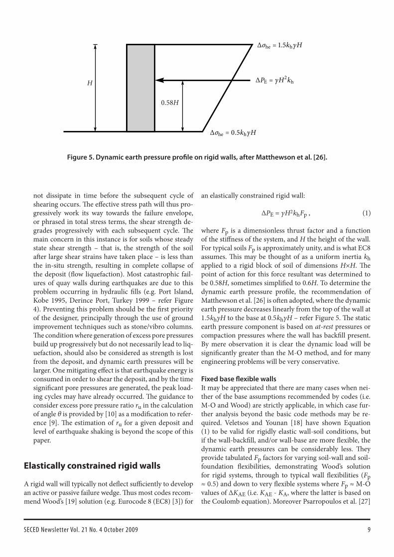
where Fp is a dimensionless thrust factor and a function of the stiffness of the system, and H the height of the wall. For typical soils Fp is approximately unity, and is what EC8 assumes. This may be thought of as a uniform inertia kh applied to a rigid block of soil of dimensions H×H. The point of action for this force resultant was determined to be 0.58H, sometimes simplified to 0.6H. To determine the dynamic earth pressure profile, the recommendation of Matthewson et al. [26] is often adopted, where the dynamic earth pressure decreases linearly from the top of the wall at 1.5 khγH to the base at 0.5 khγH – refer Figure 5. The static earth pressure component is based on at-rest pressures or compaction pressures where the wall has backfill present. By mere observation it is clear the dynamic load will be significantly greater than the M-O method, and for many engineering problems will be very conservative.
Fixed base flexible wallsIt may be appreciated that there are many cases when nei-ther of the base assumptions recommended by codes (i.e. M-O and Wood) are strictly applicable, in which case fur-ther analysis beyond the basic code methods may be re-quired. Veletsos and Younan [18] have shown Equation (1) to be valid for rigidly elastic wall-soil conditions, but if the wall-backfill, and/or wall-base are more flexible, the dynamic earth pressures can be considerably less. They provide tabulated Fp factors for varying soil-wall and soil-foundation flexibilities, demonstrating Wood’s solution for rigid systems, through to typical wall flexibilities (Fp ≈ 0.5) and down to very flexible systems where Fp ≈ M-O values of ΔKAE (i.e. KAE - KA, where the latter is based on the Coulomb equation). Moreover Psarropoulos et al. [27]
H
0.58H
∆σhe = 1.5khγH
∆PE = γH2kh
∆σhe = 0.5khγH
Figure 5. Dynamic earth pressure profile on rigid walls, after Matthewson et al. [26].
(1)
10 SECED Newsletter Vol. 21 No. 4 October 2009
showed their results compared well to FE modelling. US Army Corps Engineers [28] have adopted this method for the structural design of L-wall stems.
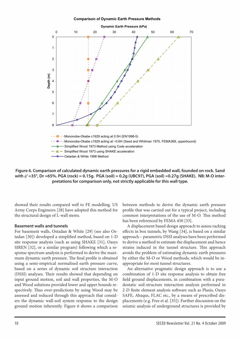
Basement walls and tunnelsFor basement walls, Ostadan & White [29] (see also Os-tadan [30]) developed a simplified method, based on 1-D site response analysis (such as using SHAKE [31], Oasys SIREN [32], or a similar program) following which a re-sponse spectrum analysis is performed to derive the maxi-mum dynamic earth pressure. The final profile is obtained using a semi-empirical normalised earth pressure curve, based on a series of dynamic soil structure interaction (DSSI) analyses. Their results showed that depending on input ground motion, soil and wall properties, the M-O and Wood solutions provided lower and upper bounds re-spectively. Thus over-predictions by using Wood may be assessed and reduced through this approach that consid-ers the dynamic wall-soil system response to the design ground motion inherently. Figure 6 shows a comparison
between methods to derive the dynamic earth pressure profile that was carried out for a typical project, including common interpretations of the use of M-O. This method has been referenced by FEMA 450 [33].
A displacement based design approach to assess racking effects in box tunnels, by Wang [34], is based on a similar approach – parametric DSSI analyses have been performed to derive a method to estimate the displacement and hence strains induced in the tunnel structure. This approach avoids the problem of estimating dynamic earth pressures by either the M-O or Wood methods, which would be in-appropriate for most tunnel structures.
An alternative pragmatic design approach is to use a combination of 1-D site response analysis to obtain free field ground displacements, in combination with a pseu-dostatic soil-structure interaction analysis performed in 2-D finite element analysis software such as Plaxis, Oasys SAFE, Abaqus, FLAC etc., by a means of prescribed dis-placements (e.g. Free et al. [35]). Further discussion on the seismic analysis of underground structures is provided by
Comparison of Dynamic Earth Pressure Methods
0
1
2
3
4
5
6
7
8
0 10 20 30 40 50 60 70
Dynamic Earth Pressure (kPa)
Dep
th (m
)
Mononobe-Okabe c1929 acting at 0.5H (EN1998-5)Mononobe-Okabe c1929 acting at ~0.6H (Seed and Whitman 1970, FEMA369, upperbound)Simplified Wood 1973 Method using Code accelerationSimplified Wood 1973 using SHAKE accelerationOstadan & White 1998 Method
Figure 6. Comparison of calculated dynamic earth pressures for a rigid embedded wall, founded on rock. Sand with ϕ’ =35°, Dr =65%. PGA (rock) = 0.15g. PGA (soil) = 0.2g (UBC97), PGA (soil) =0.27g (SHAKE). NB: M-O inter-
pretations for comparison only, not strictly applicable for this wall type.
11SECED Newsletter Vol. 21 No. 4 October 2009
Hashash et al. [36]. Kontoe et al. [37] note that such simpli-fied methods often provide reasonable results despite the inherent simplifications.
Design inertia, phase effects and amplifi-cation
Effective accelerationSarma and Yang [38] attempted to add a theoretical basis to the common practice of applying a factor of ½ or 1/3 to Peak Ground Acceleration (PGA) by considering the ac-celeration required to generate 95% of the “energy” in an earthquake record (measured in Arias Intensity), dubbed the A95 parameter. From the results of a study of 135 earth-quake recordings, a best fit correlation of A95 = 0.675×PGA was obtained. In contrast, Japanese practice adopts the proposal by Noda et al. [39] where kh is determined as fol-lows:
This is based on back-analysed estimates of kh from quay wall performance during earthquakes, and forms an upper-bound estimate, whilst a mean value is around 0.6×PGA (PIANC [5]). Al Atik and Sitar [40] found that a value of 0.65×PGA provided reasonable estimates for matching the use of M-O earth pressures centrifuge test results of em-bedded walls. The actual value will depend on the ground motion, wall geometry, soil properties, and whether lique-faction occurred. None of these empirical approaches con-siders all of these factors systematically.
Steedman and Zeng [17] investigated the assumption of infinite stiffness on dynamic active earth pressures through a pseudo-dynamic analysis method. Their results suggest phase effects on earth pressures are of small significance, but the effects of amplification were significant, and clearly both these effects would be more pronounced with large walls where peak ground velocity (PGV) rather than PGA will control the maximum inertia applied to the wall dur-ing the design earthquake.
EC8 is perhaps the first code to recommend that walls larger than 10m be considered in a site response analysis for design. Arguably this should be performed as a 2-D site response analysis that may consider the change in profile of the ground surface provided by the wall, account for the relative stiffness differences between wall and backfill, and the dynamic response of any structures present that may influence the wall behaviour. A 1-D analysis cannot capture these important aspects. Recently Anderson et al. [22] presented the results of a parametric study to con-sider these effects more systematically using QUAD4M – an equivalent linear 2-D site response program [41]. They produced a chart showing significant reduction in design
ground motion from PGA may be taken depending on the height of the wall, and the ground motion characteristics – the latter simplified as a ratio of the design spectra at a period of 1s and at PGA (i.e. relative contribution of long period to short period motion).
Displacement estimationThe most common method used to reduce the design ac-celeration from PGA, is to utilise the Newmark sliding block concept [42], originally developed for estimating co-seismic displacements of non-catastrophic embankment failures. Richards and Elms [43] adopted this method for co-seismic sliding of retaining structures in an early appli-cation of the performance based design concept. EC8 con-siders this method inherently in the analysis procedure, by allowing a reduction in design inertia kh used in conjunc-tion with the M-O method, to 0.5×PGA, implicitly allow-ing for small co-seismic displacements to occur during the design earthquake event (typically less than 10cm and therefore negligible for most applications). A simple means to estimate the order of magnitude of the displacements is also provided. However, the meaning of this reduction and the estimate of displacement is ambiguous for embed-ded walls, and caution is advised. It is recommended that the mode of deformation be considered, and for embedded walls the method of Veletsos & Younan [18] based on a shear beam model may be more appropriate.
If one wishes to consider a Newmark analysis directly, or using one of the many published empirical methods to assess sliding displacements, the implicit reduction fac-tor in EC8 should be removed, and partial factors set to unity, prior to calculation of the critical acceleration. For tilting mode displacements, the method of Steedman and Zeng [44] (see also [45]) may be applied where the wall is situated on a rigid founding stratum. For combined tilt-ing and bearing mode displacements (most applications) a modified method may be developed based on the same concepts. An alternative to the above simple rigid block models is to use a fully dynamic numerical analysis, the details of which is beyond the scope of this paper, but there are many examples in the literature.
Conclusions
This technical note summarises the common methods to assess dynamic earth pressures and their limitations. It also provides reference to modifications and enhancements to the base design methods in order to account for these limi-tations. Where possible, reference is made to Eurocode 8 to note to what extent these developments have been in-corporated into modern design. Hopefully this paper pro-vides a useful reference for understanding the subtleties of dynamic earth pressure evaluation and updates the reader on recent developments.
(2)kh = {13 (PGA)
13 if PGA ≥ 0.2g,
PGA if PGA < 0.2g.
12 SECED Newsletter Vol. 21 No. 4 October 2009
References
TAYLOR M.L.[1] Performance based design of retain-ing structures – part 1: theory. Proceedings of the 18th New Zealand Geotechnical Society 2008 Symposium.TAYLOR M.L., KONTOE S., & SARMA S. Perform-[2] ance based design of retaining structures – part 2: case study of a quay wall. Proceedings of the 18th New Zealand Geotechnical Society 2008 Symposium.BRITISH STANDARDS INSTITUTION. [3] Eurocode 8: Design of structures for earthquake resistance — Part 5: Foundations, retaining structures & geotechnical as-pects. BSI, 2004, BS EN 1998-5.STEEDMAN R.S., Seismic design of retaining walls. [4] Proc. Instn Civ. Engrs Geotech. Engng, 1998, 131, 12-22.PIANC. [5] Seismic Design Guidelines for Port Structures. International Navigation Association. Balkema, Rot-terdam, 2001.MONONOBE, N., & MATSUO, H., On the determi-[6] nation of earth pressures during earthquakes, Pro-ceedings of the World Engineering Conference, 9, 176. 1929OKABE, S. General theory of earth pressure. [7] Jour-nal of the Japanese Society of Civil Engineers, Tokyo, 12(1), 1926SEED H.B., & WHITMAN R.V. Design of earth re-[8] taining structures for dynamic loads. ASCE Special Conference on Lateral Stresses in the ground & the de-sign of earth retaining structures, Cornell, New York, ASCE 1970. 103-147MATSUZAWA, H., ISHIBASHI, I., & KAWAMURA, [9] M., Dynamic soil & water pressures of submerged soils, Journal of Geotechnical Engineering, ASCE 1985, 111, No. 10, pp 1161-1176KRAMER, S.L., [10] Geotechnical Earthquake Engineer-ing. Prentice Hall 1996, USAKUMAR J. Seismic Passive Earth Pressure Coef-[11] ficients for Sands. Canadian Geotechnical Journal, 2001, 38, 876-881.BRITISH STANDARDS INSTITUTION. E[12] urocode 7: Geotechnical design- Part I general rules. BSI 2004, BS EN 1997-1NAVAL FACILITIES ENGINEERING COMMAND.[13] Foundations & Earth Retaining Structures – Design Manual. Naval Facilities Engineering Command (NAVFAC), Washington D.C. 1986, DM7.02.KOSEKI, J., F. TATSUOKA, Y. MUNAF, M. TATEYA-[14] MA & K. KOJIMA. A modified procedure to evalu-ate active earth pressure at high seismic loads. Special Issue Soils & Foundations, 1998, 2, 209-216.INTERNATIONAL ORGANISATION for STAND-[15] ARDISATION. Bases for design of structures — Seis-mic actions for designing geotechnical works. ISO 2005, ISO 23469 [draft]JAPANESE GEOTECHNICAL SOCIETY. [16] Principles
for Foundation Designs Grounded on a Performance-based Design Concept. March 2006, Geocode 21. JGS 4001-2004STEEDMAN R.S., & ZENG X. The influence of phase [17] on the calculation of pseudo-static earth pressure on a retaining wall. Géotechnique, 1990, 40, No. 1, 103-112.VELETSOS, A.S., & YOUNAN, A.H. Dynamic Re-[18] sponse of Cantilever Retaining Walls. Journal of Geo-technical & Geoenvironmental Engineering. ASCE 1997, 123 (2):161-172WOOD J.H., [19] Earthquake Induced Soil Pressures on Structures. Report No. EERL 73-05, Earthquake En-gineering Research Laboratory, Calif. Inst. Tech., Pa-sadena. 1973.RICHARDS, R., HUANG, C., & FISHMAN, K.L., [20] (1999) Seismic Earth Pressure on Retaining Struc-tures. Journal of Geotecnical & Geoenvironmental En-gineering. ASCE 1999, 125 (9), pp. 771-778WHITMAN, R.V.[21] Seismic design of earth retaining structures. Proceeding of the 2nd International Confer-ence on Recent Advances in Geotechnical Earthquake Engineering & Soil Dynamics, Missouri, University of Missouri, Rolla, USA. 1991.ANDERSON D.G., MARTIN G.R., LAM I.P. & [22] WANG J.N. Seismic Analysis & Design of Retaining Walls, Buried Structures, Slopes, & Embankments. Vol.1. NCHRP Report 611. Transportation Research Board 2008, Washington D.C.THE OVERSEAS COASTAL AREA DEVELOP-[23] MENT INSTITUTE OF JAPAN, Technical standards & commentaries for port & harbour facilities in Japan. Eds: Goda Y., Tabata T., & Yamamoto S. OCDI 2002.EARTHQUAKE ENGINEERING FIELD INFESTI-[24] GATION TEAM. The Kocaeli, Turkey Earthquake of 17/8/99, EEFIT photo gallery. [Digital Media]. 2003.WESTERGAARD, H., Water pressure on dams dur-[25] ing earthquakes, Transactions of the ASCE, ASCE 1933, 98, pp 418-433.MATTHEWSON, M.B., WOOD, J.H. & BERRILL, [26] J.B. Seismic Design of Bridges – Earth Retaining Structures, Bulletin of the New Zealand Society of Earthquake Engineering, 1980. 13(3), 280-293PSARROPOULOS, P.N., KLONARIS, G., & GAZE-[27] TAS, G., Seismic earth pressures on rigid & flexible retaining walls. Soil Dynamics & Earthquake Engi-neering. 2005, 25, 795-809STROM R.W. & EBELING R.M. [28] Seismic Structural Considerations for the Stem & Base of Retaining Walls Subjected to Earthquake Ground Motions. ERDC/ITL TR-05-3. US Army Corps of Engineers, Engineer Research & Development Center. 2005. Washington D.C.OSTADAN, F. & WHITE, WH. Lateral Seismic Earth [29] Pressure: an Updated Approach, US-Japan SSI Work-shop 1998, USGS, Menlo Park, CA.
13SECED Newsletter Vol. 21 No. 4 October 2009
OSTADAN, F. [30] Seismic Soil Pressures for Building Walls: An Updated Approach, Soil Dynamics & Earth-quake Engineering, 2005, 25, 785-793.SCHNABEL, P.B., LYSMER, J., & SEED, H. B. [31] SHAKE: A computer program for earthquake response analy-sis of horizontally layered sites. Report EERC 72-12, Earthquake Engineering Research Centre, Univer-sity of California, Berkeley, CA. 1972.HEIDEBRECHT, A.C., HENDERSON, P., NAU-[32] MOSKI, N. & PAPPIN, J.W. Site response effects for structures located in sand sites. Canadian Geotechni-cal Journal, 27, 1990, 342-354BUILDING SEISMIC SAFETY COUNCIL. [33] NEHRP Recommended Provisions for seismic regulations for new buildings & other structures (FEMA 450). Part 2: Commentary. National Institute of Building Sciences, Washington D.C. 2004WANG J.N. [34] Seismic Design of Tunnels. A Simple State-of-the-Art Design Approach. Parsons Brincker-hoff Monograph 7. 1993, New York, NY.FREE M.W., PAPPIN, J.W., SZE J.W.C., & McGOW-[35] AN M.J. Seismic design methodology for buried structures. Proceedings 14th South East Asian Geo-technical Conference, 2001. pp 509-514.HASHASH Y.M.A., HOOK J.J., SCHMIDT B., & [36] YAO J. I.C. Seismic design & analysis of underground structures. Tunnelling & Underground Space Technol-ogy, 2001, 16, 247-293KONTOE S., ZDRAVKOVIC L., POTTS, D.M., [37] MENKITI C.O., Case study of seismic tunnel re-sponse. Canadian Geotechnical Journal, 2008, 45, 1743-1764.
SARMA, S.K., & YANG K.S. An evaluation of strong [38] motion records, & a new parameter A95. Earthquake Engineering & Structural Dynamics, 1987, 15, 119-132.NODA, S., UWABE, T. & CHIBA, T. Relation between [39] seismic coefficient & ground acceleration for gravity wall. Report of the Port & Harbour Research Institute, Japan 1975, 14, No. 4, 67–111 [in Japanese].AL ATIK, L. & SITAR, N. [40] Development of Improved Procedures for Seismic Design of Buried & Partially Buried Structures, PEER Report 2007/06, Pacific Earthquake Engineering Research Center 2007.HUDSON M., IDRISS I.M. & BEIKAE M. [41] User's Manual for QUAD4M: A computer program to evalu-ate the seismic response of soil structures using finite element procedures & incorporating a compliant base. University of California at Davis 1994.NEWMARK N. M. Effect of earthquakes on dams & [42] embankments. 5th Rankine lecture. Géotechnique. 1965, 15, 2, 139-160RICHARDS, R., & ELMS, D., Seismic Behaviour of [43] Gravity Retaining Walls, Journal of the Geotechnical Engineering Division. ASCE 1979, 15, GT4, 449-464STEEDMAN, R.S., & ZENG X., Rotation of Large [44] Gravity Walls on Rigid Foundations under Seismic Loading, In: Analysis & Design of Retaining Structures Against Earthquakes. Ed: Prakash S., ASCE 1996.ZENG X. & STEEDMAN, R.S., Rotating Block Meth-[45] od for Seismic Displacement of Gravity Walls, Jour-nal of Geotechnical & Geoenvironmental Engineering. ASCE 2000, 26 (8) 709-717.
SECEDSECED, The Society for Earthquake and Civil Engineering Dynamics, is the UK national section of the International and European Associations for Earthquake Engineering and is an affiliated society of the Institution of Civil Engineers. It is also sponsored by the Institution of Mechanical Engineers, the Institution of Structural Engineers, and the Geological Society. The Society is also closely associated with the UK Earthquake Engineering Field Investigation Team. The objective of the Society is to promote co-operation in the advancement of knowledge in the fields of earthquake engineering and civil engineering dynamics including blast, impact and other vibration problems. For further information about SECED contact:
The SecretarySECEDInstitution of Civil EngineersOne Great George StreetLondon, SW1P 3AA, UK
Or visit the SECED website:http://www.seced.org.uk
SECED NewsletterThe SECED Newsletter is published quaterly. Contributions are welcome and manuscripts should be sent on a CD or by email. Diagrams, pictures and text should be in sepa-rate electronic files. Copy typed on paper is also accept-able. Diagrams should be sharply defined and prepared in a form suitable for direct reproduction. Photographs should be high quality. Colour images are welcome. Diagrams and photographs are only returned to authors on request.
Contributions should be sent to the Editor of the Newsletter, Andreas Nielsen.
This is the second edition of a book which has become a standard text on the subject of design for blast effects since it was first published in 1995. The first edition of the book concentrated on the mechanics of design for blast loading, including blast wave propagation and structure interaction effects, structural dynamics, and design of concrete struc-tures, steel structures and glazing. The second edition ex-pands on this to take a more holistic view of addressing the threat from explosions, including whole-building response to blast and a discussion of various counter terrorism measures, which are of course becoming more prevalent in today’s society.
Generally blast loading on buildings is derived using empirical methods which have their origins in tests con-ducted by the US military in the 1950’s and 60’s, and which were presented in the Standard TM5-1300 (now supersed-ed by UFC 3-340-02). Whilst this book still concentrates on empirical techniques for the derivation of blast loading, the authors discuss the limitations of these techniques and briefly introduce phenomenological methods for deflagra-tive events, and introduce first principle methods using computational fluid dynamics to quantify complex blast-structure interaction effects.
The design of structures in reinforced concrete and steel has been brought up to date with reference to the appro-priate Eurocodes, including guidance on the selection of partial load factors and combination factors. Guidance is provided on the use of static increase factors (SIF’s) for material strengths to account for differences between char-acteristic and actual yield strengths, and dynamic increase factors (DIF’s) to account for the high strain rates experi-enced during a blast excursion. Detailing is an important aspect of designing structures to resist dynamic effects, and advice is provided on the selection of material grades and detailing rules. A new chapter is included in the Second Edition on the design of steel-concrete-steel (SCS) com-posite structures. The failure modes of SCS construction are analogous to reinforced concrete construction, but
with some subtle differences which are clearly explained in the text.
As the design of structures in steel, reinforced concrete and SCS composite is set out as three individual chapters, there is invariably some repetition in the text of these chap-ters. However, the alternative of attempting to address three different materials in one chapter may have led to confu-sion of the reader, and the repetition does not detract from a useful and informative text with clear examples.
Glazing is becoming an increasingly important element in the design of buildings, with full height glazed facades now being common place in modern buildings. The fail-ure of glazing in a blast event can lead to large scale casu-alties. The pros and cons of various types of glazing and protection systems are discussed, and a design approach presented which considers the pre-crack resistance of the glass and the post crack membrane capacity.
There is a useful chapter dedicated to whole-building response to blast damage, which looks at the prevention
New books
Blast effects on buildingsEdited by David Cormie, Geoff Mays & Peter SmithThomas Telford £65.00 pp356
Book review
Andrew MairEngineering Director, Jacobs
15SECED Newsletter Vol. 21 No. 4 October 2009
New book on EC8
Eurocode 8 has acquired the status of a full Euronorm and has been implemented in several national codes both within and beyond Europe. As part of addressing the need for practical in-formation and training, a new book has recently been published by Taylor and Francis (ISBN 978-0-415-44762-1, 336 pp). The book links the prin-ciples of seismic design to the provi-sions of Eurocode 8, illustrated with design examples. Concrete and steel buildings, and their foundations, are given special emphasis but the princi-ples are also applicable to other types of structure and sub-structure.
The book consists of nine chapters, starting with an introduction to the contents and implementation of EC8 in Chapter 1 (by Philippe Bisch). The second chapter (by Julian Bommer and Peter Stafford) provides a de-tailed review of methods used in de-termining seismic hazards and earth-
quake actions, with specific reference to the stipulations of EC8. Chapter 3 (by Martin Williams) presents a review of basic dynamics including the response of single and mul-ti-degree-of-freedom systems and the use of earthquake response spectra, leading to the seismic analysis meth-ods used in EC8. This chapter also introduces an example building that is used throughout the book to illustrate the use of EC8 in practical building design. The provisions re-lating to general considerations for the design of buildings (including regularity, capacity design, and foundation/sit-ing) are discussed in Chapter 4 (by Edmund Booth and Zygmunt Lubkowski). Chapter 5 (by Andy Campbell and Mario Lopes) focuses on reinforced concrete structures and culminates in a detailed design example. Similarly, steel and composite steel/concrete structures, together with design examples, are dealt with in Chapters 6 and 7 (by Ahmed Elghazouli and Miguel Castro). The behaviour
and design of both shallow and pile foundations, coupled with illustra-tive design examples, are covered in Chapter 8 (by Gopal Madabhushi, Indrasenan Thusyanthan, Zygmunt Lubkowski and Alain Pecker) and Chapter 9 (by Gopal Madabhushi and Robert May).
The book stems mainly from prac-tical short courses on seismic design, run jointly by SECED and Imperial College London, with contributions from leading practitioners and senior academics. The next short course is planned for September 2010; details will be announced in the SECED Newsletter and website in due course. For further information, contact Prof. Ahmed Elghazouli at Imperial Col-lege London (e-mail: [email protected]).
Seismic Design of Buildings to Eurocode 8Edited by Ahmed Y. ElghazouliTaylor & Francis £65.00 pp336
Book announcement
Ahmed ElghazouliImperial College London
of disproportionate and progressive collapse. The authors recognised that there is no universal approach to designing for robustness, and differing approaches are taken depend-ing on the codes and standards being applied. It is also rec-ognised that most of the robustness rules which have been developed around the world relate primarily to accidental actions, rather than those of malicious origin, which most blast scenarios reflect. The key issues which an Engineer
needs to consider in assessing the whole-building response to blast are set out in a clear concise manner.
The book is well written and easy to digest for those with a basic knowledge of structural dynamics. I would thor-oughly recommend this text for those interested in blast effects on buildings, whether they be students, those seek-ing an introduction to the subject matter or seasoned prac-titioners.
New books
16 SECED Newsletter Vol. 21 No. 4 October 2009
Year Day MonTime
Lat LonDep Magnitude
LocationUTC km ML Mb Mw
2009 03 JAN 19:43 0.41S 132.89E 17 7.6 PAPUA, INDONESIAAt least five people killed, over 250 injured and more than 840 buildings damaged in Manokwari and Sorong, western Papua.2009 04 JAN 05:10 36.73N 22.28E 10 4.3 SOUTHERN GREECEOne person killed and one injured (by a falling wall) in Khora Gaitson.2009 08 JAN 19:21 10.17N 84.20W 14 6.1 COSTA RICAAt least 40 people killed (including 17 still missing presumed dead), over 100 injured and more than 500 houses destroyed or damaged in central Costa Rica. The majority of the casualties were as a result of landslides in the region.2009 10 JAN 23:26 56.75N 4.37W 7 2.4 LOCH ERICHT, HIGHLAND2009 15 JAN 05:32 60.27N 1.28W 29 3.3 SHETLAND ISLANDSFelt throughout the Shetland Islands (4 EMS).2009 15 JAN 07:27 22.35S 170.64E 27 6.7 LOYALTY ISLANDS2009 15 JAN 17:49 46.86N 155.15E 36 7.4 KURIL ISLANDS2009 19 JAN 03:35 22.60S 170.91W 12 6.5 LOYALTY ISLANDS2009 20 JAN 06:51 49.20N 3.23W 13 2.1 ENGLISH CHANNEL 2009 11 FEB 17:34 3.88N 126.40E 22 7.2 TALAUD, INDONESIAAt least 64 people injured and damage to 600 buildings in Kepulauan Talaud.2009 18 FEB 21:53 27.42S 176.33W 25 6.9 KERMADEC ISLANDS2009 19 FEB 10:11 49.45N 0.52W 5 2.5 ENGLISH CHANNEL2009 19 FEB 11:44 49.45N 0.54W 5 2.1 ENGLISH CHANNEL2009 20 FEB 03:48 34.20N 73.90E 10 5.4 PAKISTANAt least 44 people injured and several landslides reported in Kashmir.2009 22 FEB 13:18 56.45N 5.29W 5 1.8 BONAWE, ARGYLL/BUTE2009 23 FEB 00:58 50.60N 1.01E 5 1.6 ENGLISH CHANNEL2009 28 FEB 10:11 64.72N 0.57E 10 3.0 NORWEGIAN SEA2009 03 MAR 14:35 51.12N 1.18E 3 3.0 FOLKESTONE, KENTFelt Folkestone (4 EMS).2009 04 MAR 12:04 51.53N 3.05W 13 1.6 NEWPORT, SOUTH WALES2009 06 MAR 10:50 80.32N 1.85W 9 6.5 NORTH OF SVALBARD2009 06 MAR 14:43 49.54N 0.83W 5 2.1 ENGLISH CHANNEL2009 08 MAR 07:37 49.58N 1.23W 5 2.2 ENGLISH CHANNEL2009 19 MAR 18:17 23.05S 174.66W 33 7.6 TONGA2009 20 MAR 07:11 49.50N 0.58W 6 2.3 ENGLISH CHANNEL2009 21 MAR 15:39 49.51N 0.16W 5 2.1 ENGLISH CHANNEL2009 26 MAR 04:44 22.68N 85.73E 10 4.1 JHARKHAND, INDIAFive people injured and several buildings damaged in Chaibasa.2009 06 APR 01:32 42.33N 13.33E 9 6.3 CENTRAL ITALYAt least 259 people killed, over 1,000 injured and more than 15,000 buildings damaged or destroyed leaving over 55,000 homeless in the L’Aquila area.
Notable Earthquakes January – June 2009Reported by British Geological SurveyIssued by: Davie Galloway, British Geological Survey, August 2009.Non British Earthquake Data supplied by The United States Geological Survey.
17SECED Newsletter Vol. 21 No. 4 October 2009
Year Day MonTime
Lat LonDep Magnitude
LocationUTC km ML Mb Mw
2009 07 APR 04:23 46.05N 151.55E 31 6.9 KURIL ISLANDS2009 07 APR 17:47 42.28N 13.46E 15 5.5 CENTRAL ITALYOne person killed and additional damage to buildings in the L’Aquila area.2009 09 APR 01:46 27.14N 70.75E 44 5.2 INDIA/PAKISTAN BORDERSix people injured and several buildings damaged in Jaisalmer, India.2009 11 APR 11:39 53.69N 0.25W 15 3.0 GOXHILL, NORTH LINCSFelt Hull, Swanland, Ulceby, Beverley and Binbrook (3 EMS).2009 11 APR 23:33 50.19N 5.15W 3 1.4 STITHIANS, CORNWALLFelt Crowlas and Rinsey, Cornwall (3EMS).2009 16 APR 14:57 60.20S 26.86W 20 6.7 STH SANDWICH ISLANDS2009 16 APR 18:48 49.55N 0.87W 5 2.3 ENGLISH CHANNEL2009 16 APR 21:27 34.19N 70.08E 6 5.4 AFGHANISTANAt least 19 people killed, 51 others injured and more than 200 homes destroyed in Nangarhar Province.2009 16 APR 23:42 34.11N 70.06E 4 5.1 AFGHANISTANFurther damage reported in Nangarhar Province.2009 18 APR 19:17 46.02N 151.43E 35 6.6 KURIL ISLANDS2009 20 APR 14:07 49.59N 0.96W 5 2.2 ENGLISH CHANNEL2009 21 APR 10:05 50.09N 0.35E 7 2.2 ENGLISH CHANNEL2009 22 APR 10:00 50.08N 0.82E 6 2.3 ENGLISH CHANNEL2009 22 APR 14:12 55.83N 3.19W 5 2.0 PENICUIK, MIDLOTHIAN2009 22 APR 16:02 50.10N 0.84E 5 1.9 ENGLISH CHANNEL2009 23 APR 17:41 50.01N 0.95E 7 2.1 ENGLISH CHANNEL2009 25 APR 19:01 50.02N 0.92E 5 2.2 ENGLISH CHANNEL2009 26 APR 05:04 50.01N 0.73E 5 2.2 ENGLISH CHANNEL2009 27 APR 14:02 50.04N 0.91E 5 2.3 ENGLISH CHANNEL2009 28 APR 08:17 50.08N 0.68E 6 2.2 ENGLISH CHANNEL2009 28 APR 10:22 54.17N 3.02W 9 3.7 ULVERSTON, CUMBRIAFelt widely across Cumbria and Lancashire (5 EMS).2009 28 APR 14:50 50.06N 0.78E 6 2.4 ENGLISH CHANNEL2009 29 APR 09:14 50.06N 0.72E 8 1.9 ENGLISH CHANNEL2009 29 APR 14:02 50.06N 0.69E 6 2.4 ENGLISH CHANNEL2009 29 APR 15:01 50.14N 0.90E 5 2.2 ENGLISH CHANNEL2009 07 MAY 11:08 56.40N 5.69W 13 1.8 ISLE OF MULL2009 16 MAY 00:53 31.52S 178.79W 55 6.5 KERMADEC ISLANDS2009 19 MAY 17:35 25.29N 37.74E 2 5.7 WESTERN SAUDI ARABIASeven people injured and several large ground cracks observed in Al Madinah.2009 28 MAY 08:24 16.72N 86.23W 10 7.3 OFFSHORE HONDURASSeven people killed, 40 others injured and more than 130 buildings either damaged or destroyed in northern Honduras.2009 29 MAY 06:20 17.03S 168.33E 13 5.7 VANUATUTen people injured and several buildings damaged on Tongoa Island.
Notable Earthquakes (continued)
18 SECED Newsletter Vol. 21 No. 4 October 2009
Year Day MonTime
Lat LonDep Magnitude
LocationUTC km ML Mb Mw
2009 02 JUN 02:17 17.76N 167.95E 15 6.3 VANUATUFour people injured and several buildings damaged on Tongoa Island.2009 04 JUN 16:45 49.54N 0.19W 10 1.7 ENGLISH CHANNEL2009 04 JUN 17:44 49.50N 0.18W 10 1.8 ENGLISH CHANNEL2009 05 JUN 19:24 51.62N 3.65W 6 2.9 MAESTEG, BRIDGENDFelt Bridgend and Vale of Glamorgan, South Wales and also in Bridgwater, Somerset (3 EMS).2009 10 JUN 04:48 49.58N 0.20W 10 2.3 ENGLISH CHANNEL2009 10 JUN 04:59 51.81N 3.42W 9 2.0 MERTHYR TYDFIL2009 13 JUN 17:17 44.72N 78.86E 15 5.4 EASTERN KAZAKHSTANOne person killed and several buildings damaged in Tekeli.2009 14 JUN 09:07 56.10N 4.33W 3 1.6 BUCHLYVIE, STIRLING2009 23 JUN 14:19 5.16S 153.78E 64 6.7 PAPUA NEW GUINEA2009 28 JUN 00:05 56.24N 3.73W 5 1.6 BLACKFORD, TAYSIDE
Notable Earthquakes (continued)
Date Venue Title Organiser
27/10/2009 IStructELondon
Engineering Analysis of an Offshore Pipeline on an Escarpment in a Seismically Active Zone: A Case Study in the CaspianSpeaker: Dr Tapan K Sen
IStructE
28/10/2009 at 6pm
ICELondon
Pile Design in Seismic AreasSpeaker: Dr Subhamoy Bhattacharya
SECEDZygmunt Lubkowski (Arup)
17/11/2009at 6.15pm
ICELondon
Scruton Lecture: Wind-induced Vibrations of StructuresSpeaker: Svend Ole Hansen
ICEThe Wind Engineering Society
25/11/2009at 6pm
ICELondon
Japanese Nuclear Power Plant and the 2007 Niigata EarthquakeSpeaker: Dr Willy Aspinall
SECEDDavid Mallard (David Mallard & Associates)
01/12/2009 7 Warwick CourtLondon
One day course: Floor vibrations in steel framed structures
IStructESCI
27/01/2010 at 6pm
ICELondon
The State of the Practice of Seismic Hazard Analysis: From the Good to the BadSpeaker: Dr Norm Abrahamson
SECEDJulian Bommer (Imperial College London)
24/02/2010 at 6pm
ICELondon
Soil-Structure Interaction Using Finite Element MethodsSpeaker: Dr Harvinder Sehmi
SECEDIan Smith (Atkins)
17/03/2010 Imperial CollegeLondon
Half-day seminar on dynamic soil properties (followed by the 2010 Rankine Lecture by Prof C R I Clayton)
SECED, BGAAndrew Coatsworth (NII)Stavroula Kontoe (Impe-rial College London)
Forthcoming events
19SECED Newsletter Vol. 21 No. 4 October 2009
For further information regarding SECED events please contact Pauline Arundel, Engineering Department, at the ICE, on telephone 020 7665 2236, email [email protected], or visit the SECED website at
http://www.seced.org.uk.
The purpose of the 2010 SECED Young Engineers' Conference is to bring together young engineers from both indus-try and universities to meet and interchange ideas related to the study and practice of earthquake engineering and civil engineering dynamics. The conference will focus on:
A number of world leading academics and practitioners will be presenting key-note lectures. There will be both poster and oral presentations. Two prizes of £100 will be given to the two best papers presented at the conference, which will also be printed in the SECED Newsletter. (To qualify for prizes, the lead author and presenter must be un-der 35 years old by 1st November 2010.)
Who should attend
Practicing engineers under the age of 35 years |Young academics under the age of 35 years |Post-doctoral researchers |Research students |MSc students |
Why you should attend
To participate in an active exchange of scientific and technical information of use both to practice and |academiaTo hear how engineers solve practical earthquake and dynamics problems |To enjoy the sites of London |
Important dates
Submission of abstracts: 30 April 2010‡
Paper/poster acceptance notification: 30 May 2010 Paper submission: 30 August 2010
† Final date to be announced.‡ Abstracts must contain an introduction, method and conclusion section and fit into 1 page of A4.
SE
S E C E DED
1st Announcement of the
SECED Young Engineers' Conferenceto be held at University College London in November 2010†
Letters In response to Stewart Gallocher’s comments in the last Newsletter Ed-mund Booth and Bryan Skipp have sent the following letter.
Dear Sir
We have read Stewart Gallocher’s comments in the June 2009 edition of the Newsletter, and have the following ob-servations.
Firstly, we greatly welcome the interest shown. The pro-posals for seismic design procedure given in the UK Na-tional Annex (NA) to Eurocode 8, and the associated com-mentary in the BSI ‘published document’ PD6698 were finalised after a very wide debate and consultation exercise, but are recognised to be a change from current practice. It was anticipated that these proposals would need to be reviewed after some years of use, to see if they required revision. Therefore, a public debate is very valuable to as-sist this process.
Secondly, Stewart rightly points out that the proposed procedure is different to that currently adopted in the US. However, it appears that he may not have fully appreciated exactly what is proposed. As the Americans realized some time ago, and subsequently implemented in their codes, designing to a return period of 475 years gives a very non-uniform level of seismic reliability (i.e. lifetime probability of collapse) between regions of high and low seismicity. The problem is even more extreme in an area of very low seismicity, such as the UK, and this is reflected in the very long return period of 2,500 years, used in conjunction with the BGS hazard maps and recommended EC8 spectral shapes, which is given as a conservative option in the UK NA. However, this applies only to the UK and might not be appropriate (nor is this anywhere suggested) for mod-erately seismic areas of Europe such as parts of southern France, or highly seismic areas such as Greece. Moreover, the US design parameter of
(1,500 year return motion/1.5)
cannot be compared directly with the design parameter in the UK NA of
(2,500 year return motion/1.0),
because the former applies to ‘ordinary’ structures, while the UK provision applies to consequence class CC3 build-ings, which have a high consequence for loss of human life or where the economic or environmental consequences are very great. It may be noted that such buildings in the USattract an `importance factor` greater than 1, whereas the
UK NA sets this factor at unity. In fact, the UK NA pro-vides that only the more critical CC3 structures need con-sider any explicit seismic design provisions, and many are exempt; ‘ordinary’ (CC2) structures are always exempt. Moreover, the UK NA and PD6698 give the alternative op-tion of selecting values of design ground motion by carry-ing out a site-specific hazard analysis; the associated return period should be chosen “accounting for the function and consequences of failure of the facility involved”. The UK NA is therefore not as conservative in relation to US prac-tice as Stewart appears to believe. Further advice and back-ground information is given in PD6698.
It is also heartening to note that a current major Eu-ropean research project, called SHARE, has as one of its objectives an examination of the appropriate measures for specifying ground motion hazard, including choice of re-turn period. A link has been established between the Eu-ropean committee responsible for Eurocode 8 and SHARE, so the results and recommendations of SHARE will be tak-en into account in the next major revision to Eurocode 8. It may be of interest to know that the seeds of SHARE – the idea of a harmonised European seismic map without ‘step functions’ at national borders – were planted by a proposal made 30 years ago by the second author of this letter, Bryan Skipp with Nick Ambraseys. It is good to know these seeds are now bearing fruit.
Yours faithfully
Edmund Booth UK National Technical Contact for EC8 & Bryan Skipp Chair, BSI committee B525/8
ReferencePD 6698:2008, Background paper to the UK National An-nexes to BS EN 1998 1, BS EN 1998 2, BS EN 1998-4, BS EN 1998-5 and BS EN 1998-6