at Lewis Field Glenn Research Center Affordable Development and Demonstration of a Small NTR Engine and Stage: How Small is Big Enough? (AIAA-2015-4524) EXPL-06 Nuclear Propulsion S. K. Borowski and R. J. Sefcik (NASA GRC) J. E. Fittje and D. R. McCurdy (Vantage Partners, LLC@GRC) A. L. Qualls and B. G. Schnitzler (ORNL) J. Werner (INL) and A. Weitzberg (DOE Consultant) C. R. Joyner (Aerojet Rocketdyne) 216-977-7091, [email protected]presented at AIAA Space & Astronautics Forum & Exposition (Space 2015) Pasadena, CA Tuesday, September 1, 2015
Transcript
at Lewis FieldGlenn Research Center
Affordable Development and Demonstration of a Small NTR
Engine and Stage: How Small is Big Enough?(AIAA-2015-4524)
EXPL-06 Nuclear Propulsion
S. K. Borowski and R. J. Sefcik (NASA GRC)
J. E. Fittje and D. R. McCurdy (Vantage Partners, LLC@GRC)
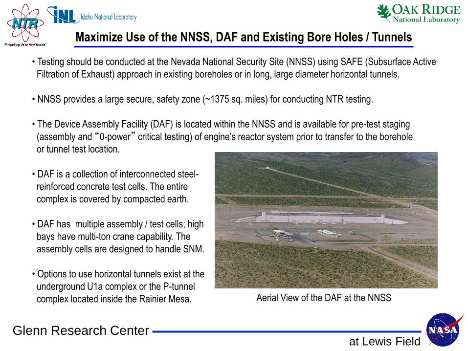
• Testing should be conducted at the Nevada National Security Site (NNSS) using SAFE (Subsurface Active
Filtration of Exhaust) approach in existing boreholes or in long, large diameter horizontal tunnels.
• NNSS provides a large secure, safety zone (~1375 sq. miles) for conducting NTR testing.
• The Device Assembly Facility (DAF) is located within the NNSS and is available for pre-test staging
(assembly and “0-power” critical testing) of engine’s reactor system prior to transfer to the borehole
or tunnel test location.
• DAF is a collection of interconnected steel-
reinforced concrete test cells. The entire
complex is covered by compacted earth.
• DAF has multiple assembly / test cells; high
bays have multi-ton crane capability. The
assembly cells are designed to handle SNM.
• Options to use horizontal tunnels exist at the
underground U1a complex or the P-tunnel
complex located inside the Rainier Mesa.
Maximize Use of the NNSS, DAF and Existing Bore Holes / Tunnels
Aerial View of the DAF at the NNSS
at Lewis FieldGlenn Research Center
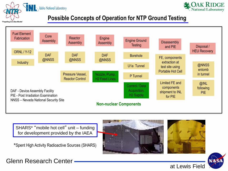
Possible Concepts of Operation for NTP Ground Testing
DAF - Device Assembly Facility
PIE - Post Irradiation Examination
NNSS – Nevada National Security Site
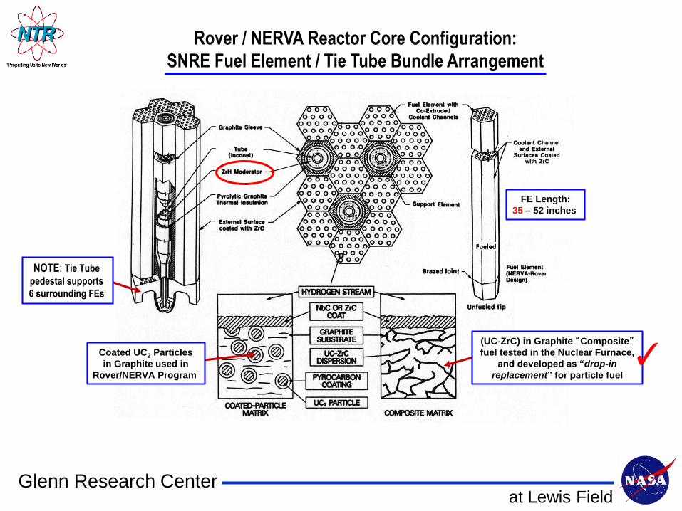
Fuel Element
FabricationCore
AssemblyEngine
Assembly
P Tunnel
Industry
ORNL / Y-12
Reactor
AssemblyEngine Ground
Testing
Borehole
Disposal /
HEU Recovery
@INL
following
PIE
Control / Data
Acquisition,
H2 Supply
Nozzle, Pump,
H2 Feed Lines
Non-nuclear Components
U1a Tunnel
Pressure Vessel,
Reactor Control
Disassembly
and PIE
@NNSS
entomb
in tunnel
Limited FE and
components
shipment to INL
for PIE
DAF
@NNSS
DAF
@NNSSDAF
@NNSSFE, components
extraction at
test site using
Portable Hot Cell
SHARS* “mobile hot cell” unit – funding
for development provided by the IAEA
*Spent High Activity Radioactive Sources (SHARS)
at Lewis FieldGlenn Research Center
Retracted Length
180.6 (in)
459 (cm)
LOX / LH2 RL10B-2
F ~24.75 klbf
211 cm / 6.9 ft
419 cm
13.7 ft Retractable
Radiation-cooled
Section
49.6 (in)
126 (cm)
Core
Length
35 (in)
88.9 (cm)
Core
Regenerative
and
Radiation-cooled
Nozzle
RL10 Fuel
Turbopump
PV Dia.
34.5 (in)
87.7 (cm)
Exit Dia.
52.1 (in)
132.3 (cm)
Retracted
Length
194.1 (in)
493 (cm)
Total
Length
243.7 (in)
619 (cm)
Retracted
Length
194.1 in
493 cm
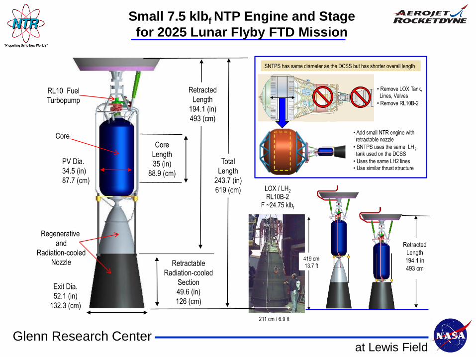
• Remove LOX Tank, Lines, Valves
• Remove RL10B-2
• Add small NTR engine with retractable nozzle
• SNTPS uses the same LH2 tank used on the DCSS
• Uses the same LH2 lines • Use similar thrust structure
SNTPS has same diameter as the DCSS but has shorter overall length
Small 7.5 klbf NTP Engine and Stage
for 2025 Lunar Flyby FTD Mission
at Lewis FieldGlenn Research Center
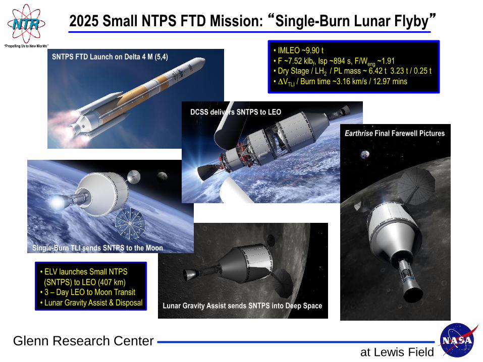
2025 Small NTPS FTD Mission: “Single-Burn Lunar Flyby”
SNTPS FTD Launch on Delta 4 M (5,4)
DCSS delivers SNTPS to LEO
Single-Burn TLI sends SNTPS to the Moon
Lunar Gravity Assist sends SNTPS into Deep Space
Earthrise Final Farewell Pictures
at Lewis FieldGlenn Research Center
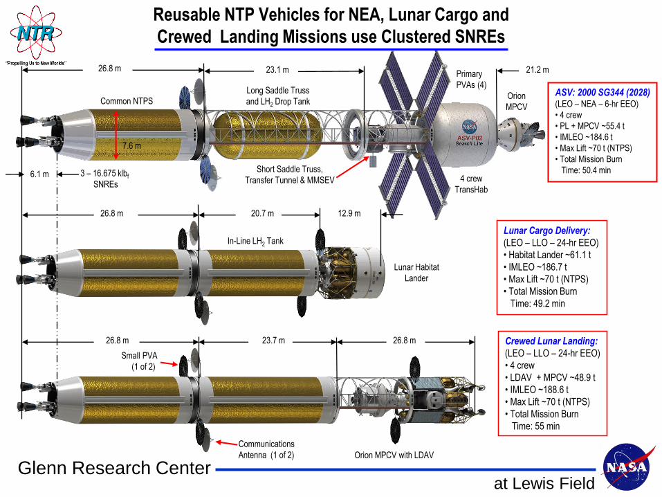
6.1 m
26.8 m 23.1 m 21.2 m
12.9 m
4 crew
TransHab
Primary
PVAs (4)
Small PVA
(1 of 2)
In-Line LH2 Tank
7.6 m
Common NTPS
Communications
Antenna (1 of 2)
3 – 16.675 klbf
SNREs
26.8 m
Lunar Habitat
Lander
Orion
MPCV
Short Saddle Truss,
Transfer Tunnel & MMSEV
Orion MPCV with LDAV
26.8 m
26.8 m
23.7 m
20.7 m
ASV: 2000 SG344 (2028)(LEO – NEA – 6-hr EEO)
• 4 crew
• PL + MPCV ~55.4 t
• IMLEO ~184.6 t
• Max Lift ~70 t (NTPS)
• Total Mission Burn
Time: 50.4 min
Lunar Cargo Delivery:
(LEO – LLO – 24-hr EEO)
• Habitat Lander ~61.1 t
• IMLEO ~186.7 t
• Max Lift ~70 t (NTPS)
• Total Mission Burn
Time: 49.2 min
Crewed Lunar Landing:
(LEO – LLO – 24-hr EEO)
• 4 crew
• LDAV + MPCV ~48.9 t
• IMLEO ~188.6 t
• Max Lift ~70 t (NTPS)
• Total Mission Burn
Time: 55 min
Long Saddle Truss
and LH2 Drop Tank
Reusable NTP Vehicles for NEA, Lunar Cargo and
Crewed Landing Missions use Clustered SNREs
at Lewis FieldGlenn Research Center
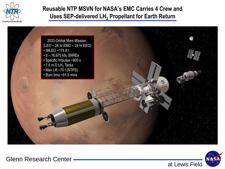
Crew Return in MAV
Reusable NTP MSVN for NASA’s EMC Carries 4 Crew and
Uses SEP-delivered LH2 Propellant for Earth Return
2033 Orbital Mars Mission:
(LEO – 24 hr EMO – 24 hr EEO)
• IMLEO ~174.8 t
• 3 – 16.675 klbf SNREs
• Specific Impulse ~900 s
• 7.6 m D LH2 Tanks
• Max Lift ~70 t (NTPS)
• Burn time ~61.5 mins
at Lewis FieldGlenn Research Center
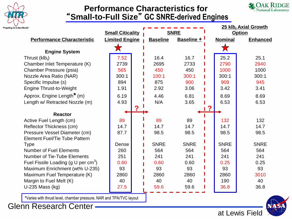
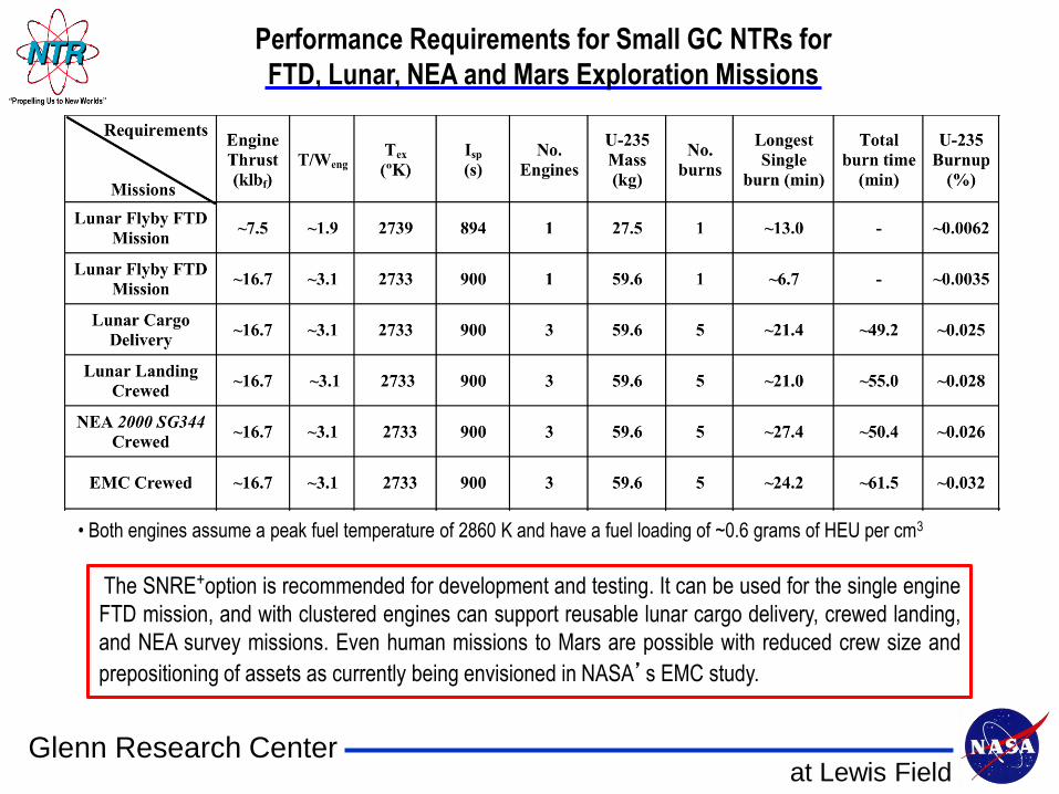
• Both engines assume a peak fuel temperature of 2860 K and have a fuel loading of ~0.6 grams of HEU per cm3
The SNRE+option is recommended for development and testing. It can be used for the single engine
FTD mission, and with clustered engines can support reusable lunar cargo delivery, crewed landing,
and NEA survey missions. Even human missions to Mars are possible with reduced crew size and
prepositioning of assets as currently being envisioned in NASA’s EMC study.
Performance Requirements for Small GC NTRs for
FTD, Lunar, NEA and Mars Exploration Missions
at Lewis FieldGlenn Research Center
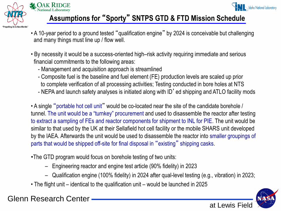
Assumptions for “Sporty” SNTPS GTD & FTD Mission Schedule
• A 10-year period to a ground tested “qualification engine” by 2024 is conceivable but challenging and many things must line up / flow well.
• By necessity it would be a success-oriented high–risk activity requiring immediate and serious
financial commitments to the following areas:
- Management and acquisition approach is streamlined
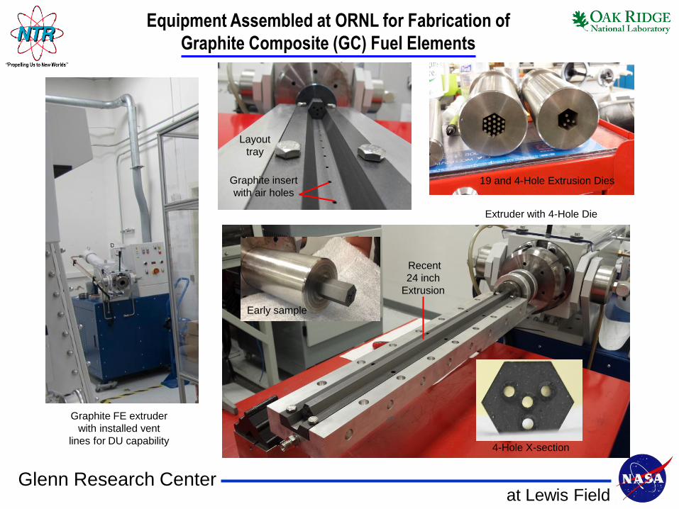
- Composite fuel is the baseline and fuel element (FE) production levels are scaled up prior
to complete verification of all processing activities; Testing conducted in bore holes at NTS
- NEPA and launch safety analyses is initiated along with ID’ed shipping and ATLO facility mods
• A single “portable hot cell unit” would be co-located near the site of the candidate borehole /
tunnel. The unit would be a “turnkey” procurement and used to disassemble the reactor after testing
to extract a sampling of FEs and reactor components for shipment to INL for PIE. The unit would be
similar to that used by the UK at their Sellafield hot cell facility or the mobile SHARS unit developed
by the IAEA. Afterwards the unit would be used to disassemble the reactor into smaller groupings of
parts that would be shipped off-site for final disposal in “existing” shipping casks.
•The GTD program would focus on borehole testing of two units:
– Engineering reactor and engine test article (90% fidelity) in 2023
– Qualification engine (100% fidelity) in 2024 after qual-level testing (e.g., vibration) in 2023;
• The flight unit – identical to the qualification unit – would be launched in 2025
at Lewis FieldGlenn Research Center
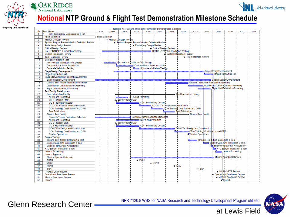
Notional NTP Ground & Flight Test Demonstration Milestone Schedule
NPR 7120.8 WBS for NASA Research and Technology Development Program utilized
at Lewis FieldGlenn Research Center
Summary and Conclusions
• In FY14, NASA and DOE (NE-75, ORNL, INL), with input from industry, formulated a preliminary
development plan for the AES program for testing a small GTD (~7.5 – 16.5 klbf) engine in the early
2020’s followed by a FTD mission of a small NTP stage around 2025
• 10-years to a FTD mission in 2025 will require an immediate start and a serious and sustained
financial commitment along with a streamlined management and acquisition approach – DOE
• Graphite-based “composite fuel” is the baseline; an engine using this fuel type can be built sooner
than one using another less established / less tested fuel at relevant conditions – DOE
• Testing should be conducted at the NNSS using existing boreholes or tunnels and should maximize
the use of existing facilities; consider new temporary / mobile facilities only as required; new nuclear
infrastructure is a long lead item – DOE
• The FTD mission proposed is a 1-burn “lunar flyby” using a single SNRE+ engine chosen to keep
things simple and more affordable; clustered SNREs can support a full range of human exploration
missions allowing a “one size fits all” approach to NTR development – GRC
• The keys to affordability include using: (1) proven “Graphite Composite” fuel; (2) “separate effects”testing (NTREES and irradiation) to qualify the fuel; (3) SOTA numerical models to design, build and
operate the engine; (4) small engine design with a “common” FE that is scalable to larger sizes, when
and if required; (5) existing DOE facilities at the NNSS (e.g., DAF, boreholes or tunnels); and (6)
flight-proven, non-nuclear engine & stage hardware to maximum extent possible for the FTD mission