61
S1000 User Manual Installation Configuration Programming Specifications
| Date post: | 15-Jun-2018 |
| Category: |
Documents |
| Upload: | truongduong |
| View: | 229 times |
| Download: | 0 times |

S1000User ManualInstallationConfigurationProgrammingSpecifications

INICOS1000 Datasheet
Important User Information
Limited Warranty
Hardware: Inico Technologies Ltd. (herafter Inico) warrants that its products are free from defects in material and workmanship for a period of 1 year from the date of invoice from Inico or its appointed distributor. The obligations of Inico under this warranty are limited to replacing or repairing, at its option, any product which shall, in the applicable period, be returned to the Inico facility, transportation charges prepaid, and which after examination is determined, to the satisfaction of Inico, to be thus defective. Products may be returned by Buyer only after permission has been obtained from Inico.Repaired or replacement Products provided under warranty are similarly warranted for a period of six (6) months from the date of shipment to Buyer or the remainder of the original warranty term, whichever is longer.This warranty shall not apply to any such equipment which shall have been :
• damaged in shipment to or from Buyer,
• repaired or altered except by Inico,
• subject to improper installation, misuse, neglect, or accident.This limited warranty is in lieu of all other warranties whether oral or written, expressed or implied.Firmware: Inico warrants for a period of one (1) year from the date of invoice from Inico or its appointed distributor, as the case may be, that standard firmware Products, when used with Inico-specified hardware, will perform in accordance with published specifications prepared, approved, and issued by Inico. Inico makes no representation or warranty, express or implied, that the operation of the firmware Products will be uninterrupted or error free, or that the functions contained therein will meet or satisfy the Buyer’s intended use or requirements. Firmware corrections are warranted for a period of three (3) months from the date of shipment to Buyer or the remainder of the original warranty term, whichever is longer.
Limited Liability
Inico’s liability shall not exceed the price of the individual unit which is the basis of the claim. In no event shall Inico be liable for any loss of profits, loss of use of facilities or equipment or other indirect, incidental or consequential damages.
Safety Guidelines
Throughout this manual, when necessary, the following notes are used to make you aware of safety considerations.
WarningIndicates a potentially hazardous situation which could lead to death or serious injury, property damage, and/or economic loss.
CautionIndicates a potentially hazardous situation which could lead to minor or moderate injury, property damage, and/or economic loss.
NoticeIndicates a potential situation which could lead to undesirable results or performance.
2

INICOS1000 Datasheet
Installation and Operation Warnings
WarningExplosion hazard, do not install in potentially explosive atmospheres.
WarningOnly qualified personnel should be allowed to install and work on this equipment. Improper installation may lead to property damage, injury, or death.
WarningThis product can only function correctly and safely if it is transported, stored, set up, and installed correctly, and operated and maintained as recommended.
3

INICOS1000 Datasheet
Table of contents
Important User Information.........................................................................................................................2 Limited Warranty.......................................................................................................................................................2
Limited Liability..........................................................................................................................................................2
Safety Guidelines......................................................................................................................................................2
Installation and Operation Warnings.........................................................................................................................3
Table of contents........................................................................................................................................4
1 Product Overview.....................................................................................................................................61.1 General Description..............................................................................................................................................6
1.2 Features...............................................................................................................................................................6
1.3 Selection Chart.....................................................................................................................................................7
1.4 Expansion Modules..............................................................................................................................................7
1.5 Web-based configuration and programming........................................................................................................8
1.6 Web-based HMI....................................................................................................................................................8
1.7 Web Services.......................................................................................................................................................9
1.8 Built-in Apps.........................................................................................................................................................9
2 Install......................................................................................................................................................112.1 Mount the Hardware...........................................................................................................................................11
2.2 Connect Power, I/O and Communication Wiring................................................................................................11
3 Initial Set Up...........................................................................................................................................143.1 Access through Web Browser............................................................................................................................14
3.2 Change IP address.............................................................................................................................................14
3.3 Set time and date...............................................................................................................................................15
3.4 Set user names and passwords.........................................................................................................................15
3.5 Run and Config start modes...............................................................................................................................16
3.6 Manual Start in Safe Mode.................................................................................................................................16
4 Configure I/O..........................................................................................................................................184.1 Onboard I/O........................................................................................................................................................18
4.2 Expansion I/O.....................................................................................................................................................20
4.3 Remote I/O.........................................................................................................................................................21
4.4 W1-Z Wireless I/O System.................................................................................................................................23
5 Program Logic Control............................................................................................................................285.1 Define Global Variables......................................................................................................................................28
5.2 Define Retained Variables..................................................................................................................................29
5.3 Add ST programs...............................................................................................................................................29
5.4 Build ST programs..............................................................................................................................................29
5.5 ST Syntax...........................................................................................................................................................30
5.6 ST Built-in Functions..........................................................................................................................................31
5.7 Tips and Avice....................................................................................................................................................32
6 Program Web Services...........................................................................................................................346.1 Introduction to Web Services..............................................................................................................................34
4

INICOS1000 Datasheet
6.2 Creating a new Web Service..............................................................................................................................34
6.3 SOAP Message configuration............................................................................................................................35
6.4 Sending and receiving SOAP messages............................................................................................................37
6.5 WSDL support....................................................................................................................................................38
7 Configure HMI Web Pages.....................................................................................................................397.1 HMI Values.........................................................................................................................................................39
7.2 HMI Parameters.................................................................................................................................................39
7.3 HMI Alarms.........................................................................................................................................................40
7.4 HMI Graphics......................................................................................................................................................43
7.5 HMI Charts.........................................................................................................................................................46
8 Send E-mail Reports...............................................................................................................................478.1 Create and E-mail Report app............................................................................................................................47
8.2 Configure SMTP Mail Server Settings................................................................................................................47
8.3 Configure Destination and Subject.....................................................................................................................47
8.4 Configure Timed Send Settings..........................................................................................................................47
8.5 Configure the E-mail contents............................................................................................................................48
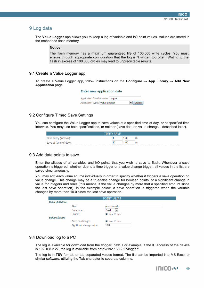
9 Log data..................................................................................................................................................499.1 Create a Value Logger app................................................................................................................................49
9.2 Configure Timed Save Settings..........................................................................................................................49
9.3 Add data points to save......................................................................................................................................49
9.4 Download log to a PC.........................................................................................................................................49
10 Technical Specifications.......................................................................................................................5010.1 Electrical characteristics...................................................................................................................................50
10.2 Environmental characteristics...........................................................................................................................51
10.3 Mechanical characteristics...............................................................................................................................52
10.4 Pin Descriptions................................................................................................................................................52
10.5 Status Indicators...............................................................................................................................................53
11 Expansion modules..............................................................................................................................5511.1 DIO8, DIO16 – Digital I/O.................................................................................................................................55
11.2 E10 – Energy Analyzer.....................................................................................................................................56
11.3 W1-Z – Wireless Module, Zigbee PRO............................................................................................................57
12 Compliance and Certifications..............................................................................................................5812.1 Electro-magnetic compatibility (EMC)..............................................................................................................58
12.2 Safety standards...............................................................................................................................................58
12.3 Hazardous locations.........................................................................................................................................58
12.4 IEC 61131-3 Compliance.................................................................................................................................58
13 Revision History....................................................................................................................................61
5

INICOS1000 Datasheet
1 Product Overview
1.1 General Description
The S1000 is a programmable Remote Terminal Unit (Smart RTU) device which offers process control capabilities, as well as a Web-based Human-Machine Interface (HMI), support for Web Services, and many more features that are described in this manual.The S1000 is designed to operate in typical industrial settings and is compatible with most industrial signal types and levels.In addition to built-in I/O ports, the S1000 supports expansion modules, which offer additional I/O points as well as specialty functions such as wireless networking and energy monitoring.
1.2 Features
• 32-bit CPU
- ARM RISC CPU running at 55MHz
- 8MB flash memory for user programs and data storage
• Logic control using IEC61131-3 Structured Text
- Web-based ST editor with syntax highlighting
- Built-in compiler, now need to install tools
• Web-based HMI
- User-configurable pages
- Graphic component library: charts, circular and linear gauges, etc
- Automatic data refresh
• Built-in apps
- E-mail reports
- Data logger
- New apps released through firmware upgrades
• 10/100 Mbit Ethernet
- Built-in Web server for configuration and monitoring
- Web Services, compliant with DPWS specifications
- Support for legacy Ethernet I/O, such as Modbus/TCP
• RS232 serial port
- User-programmable protocols
- Support for legacy I/O, such as Modbus/RTU
• CAN port (ISO11898 compliant)
- Support for legacy I/O, such as DeviceNet or CANOpen
- Support for specialty equipment, such as smart valves
• 9~36V DC digital inputs and outputs
- 8 built-in digital inputs

INICOS1000 Datasheet
- 8 built-in digital outputs
• 0-20mA, 4-20mA, 0-5V, 1-5V analogue inputs
- 4 built in analogue inputs
- Digital signal filtering
• 9~36V DC power supply
- 1W typical power consumption
• USB 1.1 device port
- Firmware upgrades with new features released periodically
• Plug-in terminal block connectors
• DIN rail mounting
• -40~85C temperature range
• EMC compliance for North America and Europe
1.3 Selection Chart
The S1000 is available in several configurations. The following chart summarizes the ordering codes and available I/O configurations.
Model 10/1
00 M
bit E
ther
net
12 M
bit U
SB P
ort
I/O E
xpan
sion
bus
8 D
igita
l Inp
uts
8 D
igita
l Out
puts
4 An
alog
Inpu
ts (4
-20m
A)
4 An
alog
Inpu
ts (0
-5V)
RS-
232,
Isol
ated
CAN
bus
, Iso
late
d
S1000.B S1000.D S1000.A S1000.DA S1000.DAV S1000.S S1000.C S1000.DS S1000.DC S1000.DASC
1.4 Expansion Modules
To meet the requirements of a wide variety of applications, the S1000 can be outfitted with up to 4 expansion modules. The following table lists available expansion modules.
Expansion Modules Type
Digital I/OInput 8x In 16x In 32x In
Output 8x Out 16x Out 32x Out
Input/Output 8x In + 8x Out 16x In + 16x Out
Analog I/O
7
INICOS1000 Datasheet
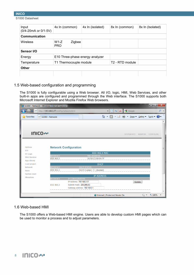
Input(0/4-20mA or 0/1-5V)
4x In (common) 4x In (isolated) 8x In (common) 8x In (Isolated)
CommunicationWireless W1-Z Zigbee
PRO
Sensor I/OEnergy E10 Three-phase energy analyzer
Temperature T1 Thermocouple module T2 - RTD module
Other
1.5 Web-based configuration and programming
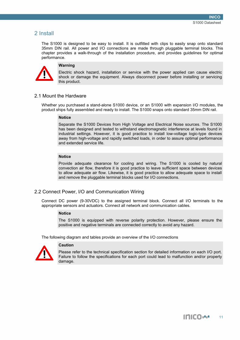
The S1000 is fully configurable using a Web browser. All I/O, logic, HMI, Web Services, and other built-in apps are configured and programmed through the Web interface. The S1000 supports both Microsoft Internet Explorer and Mozilla Firefox Web browsers.
1.6 Web-based HMI
The S1000 offers a Web-based HMI engine. Users are able to develop custom HMI pages which can be used to monitor a process and to adjust parameters.
8

INICOS1000 Datasheet
1.7 Web Services
The S1000 can be programmed to send and receive XML/SOAP messages, in order to integrate industrial processes to factory IT systems.
1.8 Built-in Apps
The HMI pages are part of a library of built-in apps which can be enabled and configured to enhance any S1000 system. Among the built-in apps are:
• E-mail reports
9

INICOS1000 Datasheet
- Generates a report on data change, or at predefined time intervals or time of day
- E-mail is sent through a SMTP server using custom user name and password
- Customizable message subjects
• Data logger
- Saves data on change, or at predefined time intervals or time of day
- Data can be saved to a PC and edited with MS Excel as a spreadsheet, or using custom software
• Other apps are periodically released via firmware upgrades
10
INICOS1000 Datasheet
2 Install
The S1000 is designed to be easy to install. It is outfitted with clips to easily snap onto standard 35mm DIN rail. All power and I/O connections are made through pluggable terminal blocks. This chapter provides a walk-through of the installation procedure, and provides guidelines for optimal performance.
WarningElectric shock hazard, installation or service with the power applied can cause electric shock or damage the equipment. Always disconnect power before installing or servicing this product.
2.1 Mount the Hardware
Whether you purchased a stand-alone S1000 device, or an S1000 with expansion I/O modules, the product ships fully assembled and ready to install. The S1000 snaps onto standard 35mm DIN rail.
NoticeSeparate the S1000 Devices from High Voltage and Electrical Noise sources. The S1000 has been designed and tested to withstand electromagnetic interference at levels found in industrial settings. However, it is good practice to install low-voltage logic-type devices away from high-voltage and rapidly switched loads, in order to assure optimal performance and extended service life.
NoticeProvide adequate clearance for cooling and wiring. The S1000 is cooled by natural convection air flow, therefore it is good practice to leave sufficient space between devices to allow adequate air flow. Likewise, it is good practice to allow adequate space to install and remove the pluggable terminal blocks used for I/O connections.
2.2 Connect Power, I/O and Communication Wiring
Connect DC power (9-30VDC) to the assigned terminal block. Connect all I/O terminals to the appropriate sensors and actuators. Connect all network and communication cables.
NoticeThe S1000 is equipped with reverse polarity protection. However, please ensure the positive and negative terminals are connected correctly to avoid any hazard.
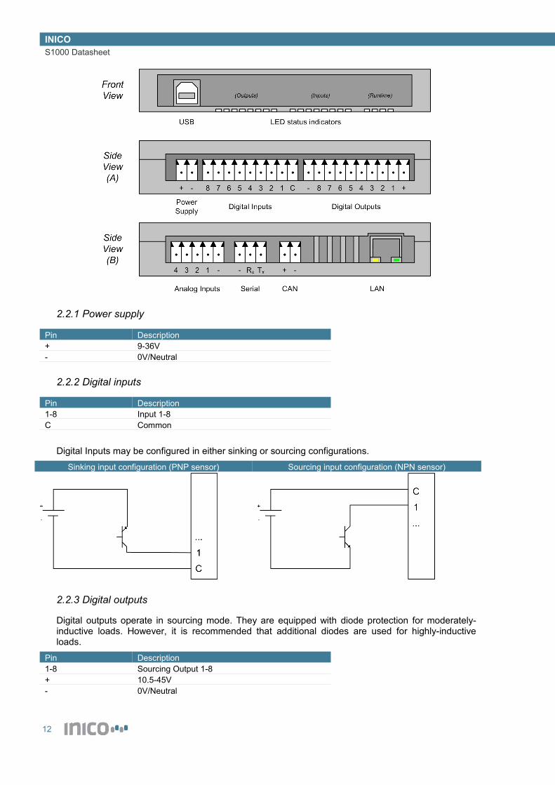
The following diagram and tables provide an overview of the I/O connections
CautionPlease refer to the technical specification section for detailed information on each I/O port. Failure to follow the specifications for each port could lead to malfunction and/or property damage.
11
INICOS1000 Datasheet
2.2.1 Power supply
Pin Description+ 9-36V- 0V/Neutral
2.2.2 Digital inputs
Pin Description1-8 Input 1-8C Common
Digital Inputs may be configured in either sinking or sourcing configurations.
Sinking input configuration (PNP sensor) Sourcing input configuration (NPN sensor)
2.2.3 Digital outputs
Digital outputs operate in sourcing mode. They are equipped with diode protection for moderately-inductive loads. However, it is recommended that additional diodes are used for highly-inductive loads.
Pin Description1-8 Sourcing Output 1-8+ 10.5-45V- 0V/Neutral
12
INICOS1000 Datasheet
2.2.4 Analogue inputs
Analogue inputs are designed for 4-20mA sensors. However, the S1000 can be shipped with 0/1-5V inputs by special order.
Pin Description1-4 Input 1-4- 0V/Neutral
2.2.5 Serial port
The serial port complies with RS232 specifications.
Pin Description- 0V/NeutralRx Received dataTx Transmitted data
2.2.6 CAN port
The CAN port complies with ISO11898 specifications.
Pin Description- CANL pin+ CANH pin
2.2.7 LAN port
The LAN port provides IEEE 802.3 10/100Mbit communications (Ethernet). Connect preferably to an industrial-rated Ethernet switch. Connect to an office network only if appropriate noise-filtering is installed.
NoticeNetwork cables can carry significant amounts of electromagnetic noise if not properly installed. Always use industrial-rated switches, or install noise filtering devices if connections to office networks are made. Failure to filter out industrial noise can lead to unexpected operation of office devices.
13

INICOS1000 Datasheet
3 Initial Set Up
3.1 Access through Web Browser
The S1000 is configured entirely through a Web interface. Devices are shipped with a pre-defined IP address, which is based on the serial number. The IP addresses are of the form:
192.168.xxx.yyywhere xxx is the first half of the serial number, and yyy is the second half of the serial number. For example, for a device with serial number 003-0045, the default IP address is 192.168.3.45.In order to access the S1000 configuration Web pages, simply type the IP address in the browser address bar.
NoticeThe computer used for configuring the S1000 must be in the same subnet as the device. A simple way to guarantee this is to use the following IP configuration:IP Address: 192.168.0.1Subnet mask: 255.255.0.0
3.2 Change IP address
In order to set a new IP address for an S1000 device, you must access Configure → Network. Simply enter the new IP address configuration and click on Update.
14

INICOS1000 Datasheet
NoticeKeep a record of the IP address used for each S1000 device. An invalid or lost IP address may lead to undesirable operation.
3.3 Set time and date
The S1000 allows automatic time and date updates using a NTP time server, or manual updates if no NTP server is available. Most modern Windows computers run a NTP server, which must be unblocked in any active firewalls. Likewise, most Linux computers can be configured to act as NTP servers. A list of public NTP servers is also available at .In order to configure automatic time and date updates using an NTP server, you must access Configuration → Network. Simply enter the IP address of the time server and the local time zone, and click on Update.
If no NTP server is available, the date and time may be set manually through Configure → Options. Please note that this time and date is lost if the device looses power or is reset.
Alternatively, the time and date may be set through logic programming using ST language. Please refer to the ST programming section of this manual. This method allows using high-accuracy external clocks, such as GPS devices.
3.4 Set user names and passwords
User names and passwords can be enabled in order to protect access to certain parts of the S1000 Web interface. The user configuration scree is available through Configure → Users. Setting allow to protect access to monitoring pages and configuration pages.
NoticeKeep a record of the user names and passwords that you enter. Failure to remember username/password combinations may lead to blocked devices. If you loose or forget your username and password and need to access the configuration screen, please contact Inico Technologies for assistance.
15

INICOS1000 Datasheet
3.5 Run and Config start modes
The S1000 can boot in three possible modes: Run, Config, and Safe Mode.
• Run: compiled ST logic programs and other apps are running, configuration interface disabled.
• Config: Configuration interface enabled, no programs or apps are running.
• Safe Mode: Configuration interface enabled, no programs or apps are running, device accessible through 192.168.0.10. Non-critical components disabled.
In order to change the start mode, update the configuration in Configure → Options.
In order to know in which mode the S1000 is running, you may observe the status LEDs visible through the clear front panel. The following table indicates the status indications.
Status L1 (Blue) L2 (Green) L3 (Yellow) L4 (Red)
Power ON On - - -
Running On On Off Off
Stopped - Configuration On Off On Off
Stopped - Safe mode On Off On On
Stopped - Error On Off Off On
3.6 Manual Start in Safe Mode
The S1000 offers the possibility to boot in “Safe Mode”, a special mode use for recovery from abnormal situations. When booting in Safe Mode, the IP Address is always 192.168.0.10.In order to enable Safe Mode and recover from an abnormal situation:1. Disconnect power from the S1000.
16

INICOS1000 Datasheet
2. Connect a USB cable to the S1000 port and to a PC port3. Connect power to the S10004. Access the S1000 configuration interface using the 192.168.0.10 address.5. Make any necessary configuration changes, such as IP address, or removing programs which
are causing errors.
17
INICOS1000 Datasheet
4 Configure I/O
The S1000 I/O system is configured entirely using the Web interface. Each I/O subsystem is referred to as an I/O module. S1000 devices are shipped with I/O modules pre-configured and ready to use. However, this section explains the entire process for adding I/O modules to the current configuration and how to set them up. All I/O modules can be added following Configure → I/O → Add new I/O module.
WarningAdding or setting up I/O modules which are not present in the S1000 assembly, or configuring the wrong kind of I/O module, can cause to unexpected results and malfunction, and lead to equipment damage and injury.
4.1 Onboard I/O
This section explains how to add and set up the onboard I/O modules, which include the built-in digital inputs, digital outputs, analog inputs, and serial port*.
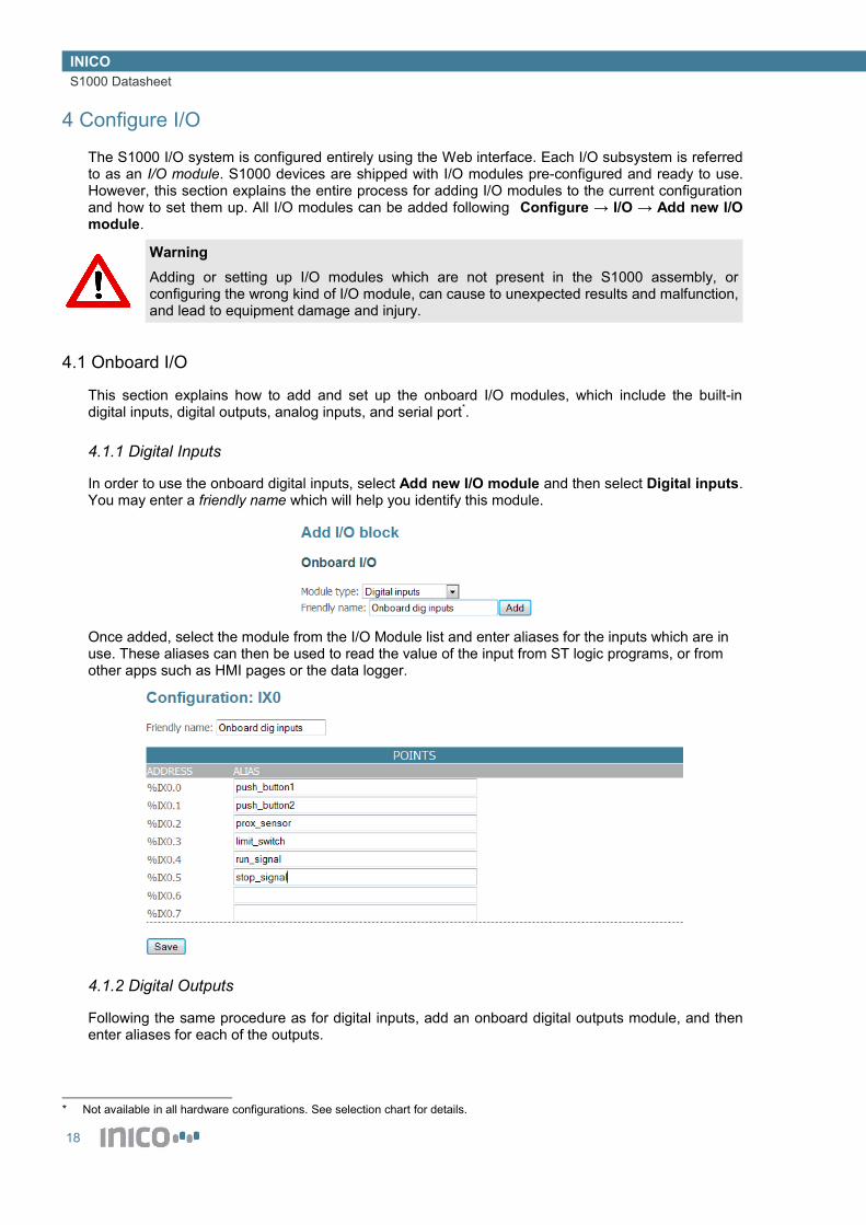
4.1.1 Digital Inputs
In order to use the onboard digital inputs, select Add new I/O module and then select Digital inputs. You may enter a friendly name which will help you identify this module.
Once added, select the module from the I/O Module list and enter aliases for the inputs which are in use. These aliases can then be used to read the value of the input from ST logic programs, or from other apps such as HMI pages or the data logger.
4.1.2 Digital Outputs
Following the same procedure as for digital inputs, add an onboard digital outputs module, and then enter aliases for each of the outputs.
* Not available in all hardware configurations. See selection chart for details.
18

INICOS1000 Datasheet
4.1.3 Analog Inputs
Following the same procedure as for digital inputs, add an onboard analogue inputs module, and then enter aliases for each of the input.
In addition, configure:
• Input type: select 4-20mA, 0-20mA, 1-5V, or 0-5V inputs
• Noise filter: select a type of filter: 2nd or 4th order FIR, IIR filter, or no filter.
• Min and Max scale: values corresponding to the input limits (e.g. 4mA value and 20mA value).
19

INICOS1000 Datasheet
4.1.4 Serial Port
Following the same procedure as for digital inputs, add an onboard RS-232 Serial Port module.
CautionIf the serial port will be used to access remote I/O, such as Modbus/RTU devices, do not add a serial port module to the configuration, or a resource conflict will occur. If a serial port is already added to the I/O configuration, remove it before adding Modbus/RTU or other serial I/O devices.
Once added, access the serial port configuration from the I/O list, and set the applicable parameters.The Onboard serial port is always assigned the COM 0 address. Serial ports in expansion modules are assigned COM 1, COM 2, etc. Use address 0 when reading or writing data in ST logic programs.
4.2 Expansion I/O
Expansion I/O modules are added in a similar way to onboard I/O modules.
Each expansion module has an assigned slot ID which is needed to identify the module in the configuration screens.
20

INICOS1000 Datasheet
For details on the configuration of expansion I/O modules, refer to the user manuals of the respective products.
4.3 Remote I/O
The S1000 is compatible with a number of fieldbus protocols, and can therefore read and write I/O points on remote I/O devices.
4.3.1 Modbus/RTU
The S1000 is capable of acting as a Modbus/RTU master, reading and writing discrete and analog values for Modbus/RTU slaves. The Modbus/RTU protocol operates through the built-in RS-232 port. An external RS-232 to RS-485 converter may be necessary in some applications.
CautionWhen using the Modbus/RTU capabilities, the serial port cannot be used by other subsystems of the S1000. The serial port must be removed from the I/O Module list, if it has been added. Failure to remove the serial port from the I/O Module list will result in a resource conflict and may lead to unexpected results.
The first step in configuring the S1000 as a Modbus/RTU master is to add a Modbus/RTU Scanner module.
Once added, the Modbus Scanner must be configured. In addition to the standard serial port parameters, a scan interval must be specified. This interval specifies how often values on remote I/O are read and written.
Once a scanner has been added, Modbus register blocks can be added. This includes coils, discretes, registers, and holding registers.
To configure a register block, select it from the I/O module list. Then, configure the slave address and register start address and quantity. Finally, type an alias for each point. The same process is used for all types of Modbus registers.
21

INICOS1000 Datasheet
4.3.2 Modbus/TCP
The S1000 is capable of acting as a Modbus/TCP client, reading and writing discrete and analog values for Modbus/TCP servers. The Modbus/TCP protocol operates through the built-in Ethernet port.
CautionThe Modbus/TCP and Modbus/RTU functions cannot be used simultaneously. Using both systems will result in a resource conflict and may lead to unexpected results.
The first step in configuring the S1000 as a Modbus/TCP client is to add a Modbus/TCP Scanner module.
Once added, the Modbus Scanner must be configured. In addition to the IP Address and TCP port parameters, a scan interval must be specified. This interval specifies how often values on remote I/O are read and written.
4.3.3 DeviceNet
Please contact Inico Technologies for more information.
22
INICOS1000 Datasheet
4.3.4 CANOpen
Please contact Inico Technologies for more information.
4.4 W1-Z Wireless I/O System
The S1000 can communicate through wireless networks, using appropriate expansion modules. One of these modules is the W1-Z, which supports wireless networks using the Zigbee PRO communication standard. Features of this system are:
• Zigbee PRO network
IEEE 802.15.4 radio
250kbps data rate
100m range per link
Mesh networking, multi-hop packet routing
Potentially 100s of devices in a network
• Support for digital and analog points
Up to 256 digital points per device
Up to 16 analog points per device, 16-bit resolution
• Smart data transfer
Update values on change (event-based system) or on timeout (scan-based system)
Configurable triggers
4.4.1 Devices a W1-Z Network
An S1000 device with a W1-Z module can take one of two roles: network coordinator, or endpoint+router. In addition, other Inico Wireless I/O devices can join the network as endpoint+router or as sleeping endpoints.
• Network Coordinator: there must be one and only one network coordinator device in every network. This devices coordinates other devices joining and leaving the network, and organizes the network structure. The network coordinator also acts as a bridge between wireless devices, and as a gateway between the wireless network and a wired network.
• Endpoint+router: all S1000 devices which are not the coordinator act as Endpoint+router nodes. The first role as endpoint is to provide read-only and read-write registers to the wireless network. In addition, these devices can act as routers in the mesh network, relaying messages from other devices to/from the coordinator.
• Sleeping endpoint: these are battery-powered sensors, which are able to go to sleep mode in order to conserve power. For a full list of available wireless sensors, please see the Inico catalog.
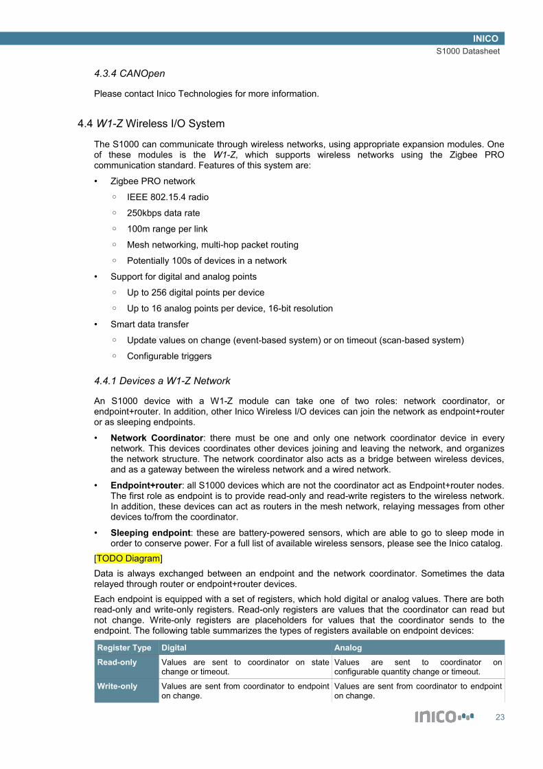
[TODO Diagram]Data is always exchanged between an endpoint and the network coordinator. Sometimes the data relayed through router or endpoint+router devices.Each endpoint is equipped with a set of registers, which hold digital or analog values. There are both read-only and write-only registers. Read-only registers are values that the coordinator can read but not change. Write-only registers are placeholders for values that the coordinator sends to the endpoint. The following table summarizes the types of registers available on endpoint devices:
Register Type Digital Analog
Read-only Values are sent to coordinator on state change or timeout.
Values are sent to coordinator on configurable quantity change or timeout.
Write-only Values are sent from coordinator to endpoint on change.
Values are sent from coordinator to endpoint on change.
23

INICOS1000 Datasheet
4.4.2 W1-Z Coordinator
The first step in deploying a W1-Z network is to configure an S1000 to act as network coordinator. In order to do so, a W1-Z Coordinator module needs to be added.
CautionWhen using the W1-Z module as a coordinator, all other I/O modules are disabled (except for the onboard serial port). Do not attempt to use I/O modules (such as digital I/O or analog inputs), as this will create a resource conflict and may lead to unexpected results. This limitation only applies to the coordinator device.
The next step is to configure the coordinator. Three parameters must be set:
• Extended PAN ID: The extended PAN ID is the unique identifier for the wireless network being created. It is a 64-bit identifier, which is encoded as 16 hexadecimal characters (0-9 and A-F). Choose an Extended PAN ID that is a unique number.
• Short PAN ID: The Short PAN ID is a short version of the extended PAN ID. After joining the network, devices use the Short PAN ID to save bandwidth. The Short PAN ID is a 16-bit number encoded as 4 hexadecimal characters. Choose an Extended PAN ID which is not in use within the are where the network will be deployed.
• Radio Channel: select one of 16 available radio channels. Select a radio channel which is not being used in the deployment area.
CautionUsing a duplicate PAN ID or reusing a radio channel may lead to unexpected results.
NoticeRemember to document the network parameters, as these will be needed when configuring other devices in the network.
After the coordinator module has been configured, the next step is to add remote registers to the configuration. Remote registers allow creating a local image of the registers in remote devices. There are four types of registers:
• Read-only digital registers: treated as digital inputs at the coordinator, values are received from the remote device.
• Write-only digital registers: treated as digital outputs at the coordinator, values are sent to the remote device.
24

INICOS1000 Datasheet
• Read-only analog registers: treated as integer inputs at the coordinator, values are received from the remote device.
• Write-only analog registers: treated as integer outputs at the coordinator, values are sent to the remote device.
In order to add remote registers, add a new I/O module with the types of registers that shall be used.
Then, select the I/O module from the list and configure the remote endpoint address, and provide aliases to those points that shall be used.
4.4.3 W1-Z Endpoint
In order to add an S1000 device to a wireless network, a W1-Z Endpoint module needs to be added.
Once added, the appropriate configuration parameters must be set. These include the Extended PAN ID, which must match the one used in the Network Coordinator, and a node address which will identify this S1000 unit in the wireless network.In addition, publish parameters must be configured in order to control when read-only register values are sent/published to the coordinator:
• Publish digital/analog values on change: defines whether values are sent to the coordinator on change (event trigger).
• Analog value change trigger: the quantity of change required to trigger a change event for analog values.
• Value publish interval: defines a timeout after which the read-only values are published, in case no change events are triggered. Can be used for periodically sending values if change triggers are disabled.
• Heartbeat interval: defines the interval at which to publish a heartbeat, which contains status information.
25

INICOS1000 Datasheet
After the endpoint module is configured, it is time to add wireless registers to the configuration.
Provide aliases to the registers which shall be used, in order to be able to access them from ST logic programs and other apps such as HMI pages.
4.4.4 W1-Z Configurator
Most battery-powered wireless sensors in the Inico catalog do not have a Web-based configuration interface. In order to set their parameters, a special configuration network needs to be created. The configuration parameters are then sent via this wireless network to the sensor.In order to set up a S1000 as a wireless sensor configurator, a Configurator module must be added.
26

INICOS1000 Datasheet
This configurator node is a Network Coordinator with predefined network parameters, which all wireless sensors have pre-configured. The parameters can be viewed by selecting the Configurator module from the I/O Module list.
Once the S1000 is started in Run mode, a configurator page will appear in the Monitor → HMI Pages list. This page will list wireless sensors which are currently connected to the configuration network, and allows sending network and publish parameters for when the sensor is started in Run mode.
27

INICOS1000 Datasheet
5 Program Logic Control
The S1000 can be programmed to perform logic control using the IEC61131-3 Structured Text (ST) language. This chapter specifies how to use this tool and provides some guidelines. The configuration of ST Logic Programs is available through the Web interface at Configure → ST Logic.
5.1 Define Global Variables
The first step is to define the variables that will be used in the logic programs. All programs share a set of global variables, local variables are not allowed. To access the global variables, follow the Edit link next to the Global Variables label.
5.1.1 Variable declaration syntax
VAR Syntax VAR ExampleVAR_GLOBAL (identifier : type[(capacity)] [:= initial_value];)*END_VAR
VAR_GLOBAL myBooleanVar : BOOL; myOtherBooleanVar : BOOL := TRUE;
myIntVar : INT; myOtherIntVar : INT := 123;
myRealVar : REAL := 123.45;
myStringVar : STRING(20) := ‘Hello World!’;END_VAR
Notes:
28

INICOS1000 Datasheet
1. Supported types are BOOL, INT, DINT, REAL, STRING2. String variables must define a capacity3. Integers can be declared as types INT or DINT (Double INT). Although INTs are
standardized as 16-bit values, both INT and DINT are treated as 32-bit signed integers, due to the 32-bit architecture of the S1000.
4. Identifiers are case insensitive.
5.2 Define Retained Variables
The S1000 allows defining retained variables. In order to access the retained variable list, click on the Edit link next to the Retained Variables label. In order to add a retained variable, enter the alias of the variable and click on Add.
Retained variables are not saved automatically, they must be saved by the user through the SAVE_RETAIN() function in ST logic.
CautionRetained variables are saved to Flash memory. Flash memory has a maximum erase/write life of 100.000 cycles. Beyond this number of writes, results can be unexpected. Use the SAVE_RETAIN() function with caution in order not to exceed this maximum.
5.3 Add ST programs
ST Programs can be added by using the Add New button. Follow the Edit link in order to edit the program.
5.4 Build ST programs
Once that the programming work is completed, you must Build the programs (internal compilation). Use the Build button to compile all programs. If any errors are encountered during compilation, a descriptive message will be shown, together with a link to the corresponding program.
29

INICOS1000 Datasheet
5.5 ST Syntax
This section describes the syntax used in ST programs. For a more complete reference, please refer to the IEC 61131-3 standard.
5.5.1 Assignment statements
Example expression:result := A + B - C;
Operands:
Operation SymbolParenthization ( Expression )Function evaluation Identifier (argument list), e.g. ABS(X)Exponentiation **Negation -Complement NOTMultiply *Divide /Modulo MODAdd +Subtract -Comparison <, >, <=, >=Equality =Inequality <>Boolean AND & ANDBoolean exclusive OR XORBoolean OR OR
5.5.2 Conditional statements
IF Syntax IF ExampleIF condition THEN
Statement_list;[ELSIF condition THEN
Statement_list;][ELSE
Statement_list;]END_IF
D := B*B-4*A*C;IF D < 0.0 THEN NROOTS := 0;ELSIF D = 0.0 THEN NROOTS := 1;ELSE NROOTS := 2;END_IF;
5.5.3 Iteration statementsFOR Syntax FOR ExampleFOR var := init_value TO end_value [BY step] DO
FOR i := 1 TO 100 BY 2 DO
30

INICOS1000 Datasheet
Statement_list;END_FOR;
j := i * 2;END_FOR
WHILE Syntax WHILE ExampleWHILE expression DO
Statement_list;END_WHILE;
i := 1;WHILE i < 100 DO j := i + 2;END_WHILE;
REPEAT Syntax REPEAT ExampleREPEAT
Statement_list;UNTIL expressionEND_REPEAT;
i := 1;REPEAT j := i + 2;UNTIL i >= 100 END_REPEAT;
5.5.4 Return statement
RETURN Syntax RETURN ExampleRETURN; IF error = true THEN
RETURN;END_IF
5.6 ST Built-in Functions
This section describes the supported ST functions, both standard functions and S1000-specific functions.
5.6.1 Flow control
WAIT (milliseconds) – suspends execution of the program for the specified number of milliseconds.WAIT_UNTIL (expression) – suspends execution of the program until the expression becomes true.
5.6.2 Retained variables
SAVE_RETAIN () – saves the retained variables to flash memory.
5.6.3 Serial port
SERIAL_GETC (port) – returns the first byte from the in_buffer of the selected COM port, or -1 if buffer empty.
SERIAL_READ(port, string, count) – reads into string up to count bytes from the in_buffer of the selected COM port. Read data is appended, existing contents of string are not overwritten. Returns the number of bytes effectively read.
SERIAL_PUTC (port, char) - places a byte in the out_buffer of the selected COM port.SERIAL_WRITE (port, string) – copies an entire string to the out_buffer of the selected COM port.
5.6.4 String manipulation
BOOL_TO_STR (bool, string) – converts the Boolean value to a string (“true” or “false”)INT_TO_STR (int, string) – converts the Integer value to a string (e.g. “123”)
31
INICOS1000 Datasheet
INT_TO_HEX (int, string) – converts the Integer value to a string in hexadecimal representation (e.g. “A528DF01”)
REAL_TO_STR (real, string) – converts the Real (float) value to a string (e.g. “123.45”)STR_TO_BOOL (string) – returns the parsed value of the string as a Boolean.STR_TO_INT (string) – returns the parsed value of the string as an Integer.STR_TO_REAL (string) – returns the parsed value of the string as a Real (float).
STR_LEN (string) – returns the number of characters in the string.STR_LEFT (string1, string2, n) – copies n characters from string1 to string2, counting from the left.STR_RIGHT (string1, string2, n) – copies n characters from string1 to string2, counting from the right.STR_MID (string1, string2, start, n) – copies n characters from string1 to string2, counting from the
character at index start.STR_CONCAT (string1, string2) – appends string1 to string2.STR_FIND (string1, string2) – returns the index of the first occurrence of string1 within string2, or -1 if
not found.
STR_CHAR (string, n) – returns the character found at index n.STR_PEND (string, c) – appends character c to string.
5.6.5 Date and time
DATETIME (string) – writes the current date and time to a stringTIME_MILLIS () – gets the number of milliseconds elapsed since logic execution started.SET_TIME (int, int, int, int) – sets the current time, parameters are hh:mm:ss.mmmSET_DATE (int, int, int) – sets the current time, parameters are yyyy/mm/dd
5.6.6 Web Services
WS_PUBLISH (message) – publishes the specified message to all subscribers.WS_RESPOND (message) – responds to a received WS command with the specified message.WS_SEND (message, address) – sends the specified message to address.WS_GET_RESPONSE (message) – returns a response code according to the status of the message transmission following WS_SEND.
For more information on Web Services commands, please see the Web Services section.
5.7 Tips and Avice
CautionVerify that your code is free of deadlocks, such as infinite loops. Deadlocks will cause the controller to freeze, which could lead to unexpected results leading to equipment damange and/or injury.If a deadlock occurs, a watchdog timer will detect this condition and reset the controller.
NoticeWhen running ST programs for the first time, consider accessing the Monitor → Statistics
32

INICOS1000 Datasheet
page in order to verify proper runtime parameters. Verify that there is sufficient memory to load all programs, and verify the execution time to ensure that there are no scan cycle overruns.
33
INICOS1000 Datasheet
6 Program Web Services
This chapter explains how to set up the S1000 to use Web Services, which are used to easily integrate industrial processes to PC software applications.
6.1 Introduction to Web Services
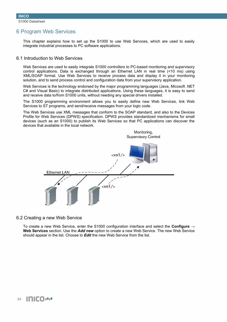
Web Services are used to easily integrate S1000 controllers to PC-based monitoring and supervisory control applications. Data is exchanged through an Ethernet LAN in real time (<10 ms) using XML/SOAP format. Use Web Services to receive process data and display it in your monitoring solution, and to send process control and configuration data from your supervisory application.Web Services is the technology endorsed by the major programming languages (Java, Micosoft .NET C# and Visual Basic) to integrate distributed applications. Using these languages, it is easy to send and receive data to/from S1000 units, without needing any special drivers installed.The S1000 programming environment allows you to easily define new Web Services, link Web Services to ST programs, and send/receive messages from your logic code.The Web Services use XML messages that conform to the SOAP standard, and also to the Devices Profile for Web Services (DPWS) specification. DPWS provides standardized mechanisms for small devices (such as an S1000) to publish its Web Services so that PC applications can discover the devices that available in the local network.
6.2 Creating a new Web Service
To create a new Web Service, enter the S1000 configuration interface and select the Configure → Web Services section. Use the Add new option to create a new Web Service. The new Web Service should appear in the list. Choose to Edit the new Web Service from the list.
34

INICOS1000 Datasheet
The first step to configure is the ServiceID and the Service Types:
• ServiceID (mandatory): this is the unique identifier for this Web Service. It is recommended to select and ID value that is meaningful and unique within the network. For example, choose and ID value of “Conveyor23” for the Web Service associated to the 23rd conveyor in an assembly line. White spaces are allowed in the Service ID, but strongly discouraged as some PC applications might have problems handling white spaces.
• Service Types (optional): a list of types that describe this type of service, separated by spaces. Service types allow you to categorize Web Services, which is useful to organize and work with all the Web Services in a particular network. For example, choose a type of “Conveyor” for all Web Services associated to conveyors in an assembly line. Service types are optional, but strongly encouraged for medium to large systems where many Web Services deployed.
Once you have entered the Service ID and optionally the service types, click on the Save button.
6.3 SOAP Message configuration
A Web Service provides an interface to an industrial process that is being monitored and/or controlled by an S1000 unit. As such, a Web Service is a collection of several incoming and outgoing XML messages. These messages are formatted according to the SOAP standard.
6.3.1 Message types
There are three types of messages that can be added to a Web Service:
35

INICOS1000 Datasheet
• Input messages: these are messages that are sent from a PC application to the S1000. Typically, these messages will convey commands to execute a particular action, or can also be used to transfer configuration data. They can also be used to request data, such as the state of a process that is being executed or the value of a measured parameter. A response message (S1000PC) can be configured, or left blank if not used.
• Output: these are messages that are sent from the S1000 to a PC application. As with input messages, they may or may not use a response message.
• Event messages: these are messages that are sent from the S1000 to one or more PC applications. Typically, these messages will report events such as the completion of a process, a significant change in a process parameter, or a fault/error/warning condition. In order to receive a copy of these messages, PC applications must subscribe to the S1000, so that an internal list of interested applications can be maintained. The number of subscribed applications for an event message can be zero, one, or many.
6.3.2 Input message configuration
To add an input message to a Web Service, click on the Add new button from the Input Message list. A blank message will be added to the list.Three parameters need to be configured for an input message:
• Alias (mandatory): used as a reference to this message from ST logic. Duplicate aliases for different messages are not allowed.
• Program name (mandatory): the name of the ST program to be executed when this message is received. This must be a valid name from one of the saved ST programs.
• Action (mandatory): used to identify the type of this message. Different types of messages have a different Action parameter, but if the same message is re-used in different S1000 units, then the same action should be used each time. As a convention, the action parameter is a Web URL, e.g. http://www.inicotech.com/soap/ConveyorStart. This makes it easy to generate unique Actions for each type of message. Optionally, a Web Page can be loaded at the specified location in order to describe the message. This serves as a good reference for programmers.
• Response Action (optional): used to identify the type of the response message generated, if any. If no response message is to be generated, this field should be left blank.
6.3.3 Output message configuration
To add an output message to a Web Service, click on the Add new button from the Output Message list. A blank message will be added to the list.Two parameters need to be configured for an output message:
• Alias (mandatory): used as a reference to this message from ST logic. Duplicate aliases for different messages are not allowed.
• Action (mandatory): used to identify the type of this message. The same rules as for an input message apply.
• Response Action (optional): used to identify the type of the response message to be received, if any. If no response is expected, this field should be left blank.
36

INICOS1000 Datasheet
6.3.4 Event message configuration
To add an event message to a Web Service, click on the Add new button from the Event Message list. A blank message will be added to the list.Two parameters need to be configured for an event message:
• Alias (mandatory): used as a reference to this message from ST logic. Duplicate aliases for different messages are not allowed.
• Action (mandatory): used to identify the type of this message. The same rules as for an input or output message apply.
6.3.5 XML configuration
Once that all input, output, and event messages have been added, it’s time to specify the actual XML content of each message.To generate or edit the XML data contained by each message, select the Edit option next to the corresponding message entry. An XML editor screen will be displayed.Type in, or copy-and-paste from an existing file, the XML structure of the message. In order to make the value of an element or attribute variable, type the alias of a string variable as the value of the element or attribute, preceded by the '$' character. If this is an input/command message, the received value of the element/attribute will be copied to the named variable. If this is an output/response or event message, the value of the variable will be used when the XML message is generated. Element and attribute values which are not of the '$variable' form will be treated as constants.
NoticeIn this step, the SOAP Body contents are specified. The SOAP Headers are automatically set up by the S1000 according to WS-Addressing.If the entered XML has an error, the entire SOAP message will be shown on the next edit. In this case, fix the Soap Body part to ensure XML compliance, and leave the SOAP Envelope and Header untouched.
6.4 Sending and receiving SOAP messages
6.4.1 Working with Input messages
For input messages, when the message is received, the named ST Program will be executed. If any variable data was sent with the message, it will be available from the string variables configured in the XML message structure.In addition to executing any logic, the ST program must send back a response message, using the WS_RESPOND(msg_alias). Even if no SOAP response is configured, a WS_RESPOND(msg_alias) should be used to send an empty response back. Any parameters for the response message must be set before calling WS_RESPOND(msg_alias).
6.4.2 Sending output messages
If an output message is to be sent to a PC application, the command WS_SEND(msg_alias, service_address) can be used from any ST program. The message will be automatically sent to the specified service. In order to check when a response has been received, or to check if there were any
37
INICOS1000 Datasheet
errors in the communication, the command WS_GET_RESPONSE(msg_alias) is used. The return codes for this command are:
0 – Response not received1 – Response received OK2 – SOAP Fault received3 – Unexpected response type/action4 – Malformed response, not valid XML5 – Connection error, could not connect to destination web service6 – Bad address, address not valid7 – Out of memory error
6.4.3 Sending event messages
If an event message is to be sent to all subscribed PC applications, the command WS_PUBLISH(msg_alias) can be used from any ST program. A copy of the message will be automatically sent to every subscribed PC application. If no applications are subscribed, the event isn’t sent through the network at all.
6.4.4 ST Command summary
The following two commands are used from ST programs to send XML/SOAP messages:
• WS_RESPOND(msg_alias): a response to an input/command message is generated and sent back. Any variable data should be set/copied to the corresponding string variables before this command is invoked.
• WS_SEND(msg_alias, destination_address): an output message is sent to destination_address. Any variable data should be set/copied to the corresponding string variables before this command is invoked.
• WS_GET_RESPONSE(msg_alias): Returns a response code according to the status of the output message transmission.
• WS_PUBLISH(msg_alias): an event message is generated and sent to every subscribed PC application. Any variable data should be set/copied to the corresponding string variables before this command is invoked.
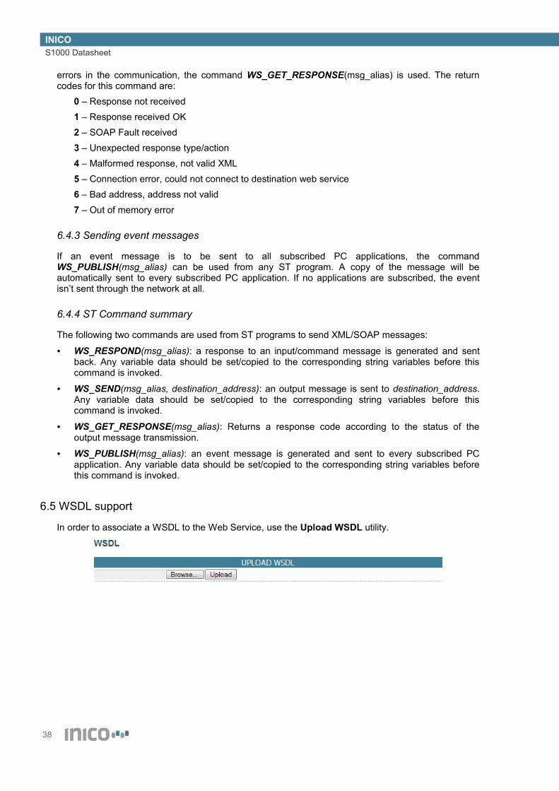
6.5 WSDL support
In order to associate a WSDL to the Web Service, use the Upload WSDL utility.
38

INICOS1000 Datasheet
7 Configure HMI Web Pages
The S1000 is equipped with an HMI engine, which allows you to develop custom Web pages to display real-time process data. All HMI Pages are added by accessing Configure → App Library and clicking on Add New Application. Each HMI Page is treated as an individual app.
NoticeIn order to enable proper rendering and real-time refresh of HMI Pages, please make sure that your browser has Javascript enabled.
7.1 HMI Values
HMI Values are used to display a list of variable and I/O point values, together with a description of the value. It is the simplest form of HMI pages. The values are updated automatically on screen. In order to add an HMI Values page, create a new app of the corresponding type.
Once created, follow the edit link to set the page configuration, including a page title, refresh interval, and values to display.
When the S1000 is started in Run mode, the page will be available in the Monitor → HMI section.
7.2 HMI Parameters
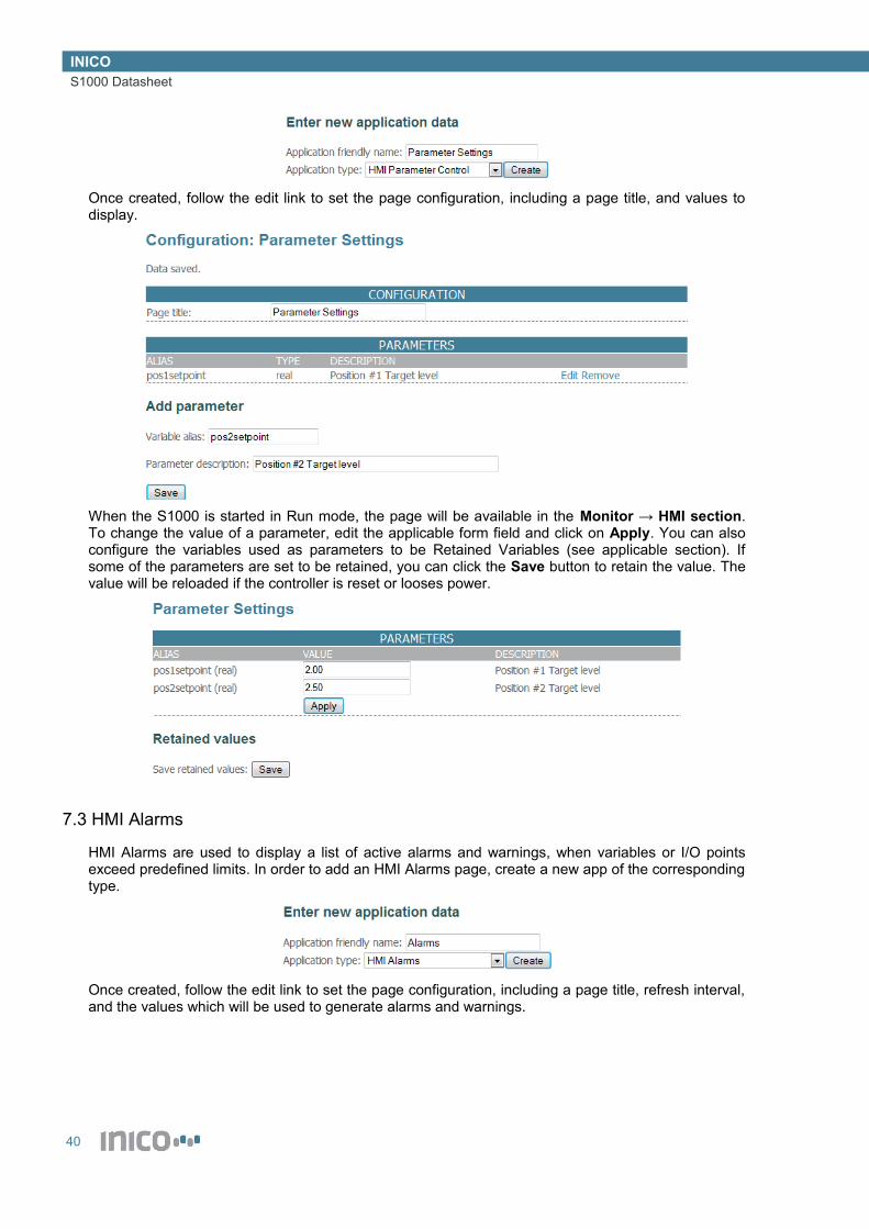
HMI Parameters are used to display a list of parameter values, which can be modified by an operator. In order to add an HMI Parameters page, create a new app of the corresponding type.
39
INICOS1000 Datasheet
Once created, follow the edit link to set the page configuration, including a page title, and values to display.
When the S1000 is started in Run mode, the page will be available in the Monitor → HMI section. To change the value of a parameter, edit the applicable form field and click on Apply. You can also configure the variables used as parameters to be Retained Variables (see applicable section). If some of the parameters are set to be retained, you can click the Save button to retain the value. The value will be reloaded if the controller is reset or looses power.
7.3 HMI Alarms
HMI Alarms are used to display a list of active alarms and warnings, when variables or I/O points exceed predefined limits. In order to add an HMI Alarms page, create a new app of the corresponding type.
Once created, follow the edit link to set the page configuration, including a page title, refresh interval, and the values which will be used to generate alarms and warnings.
40
INICOS1000 Datasheet
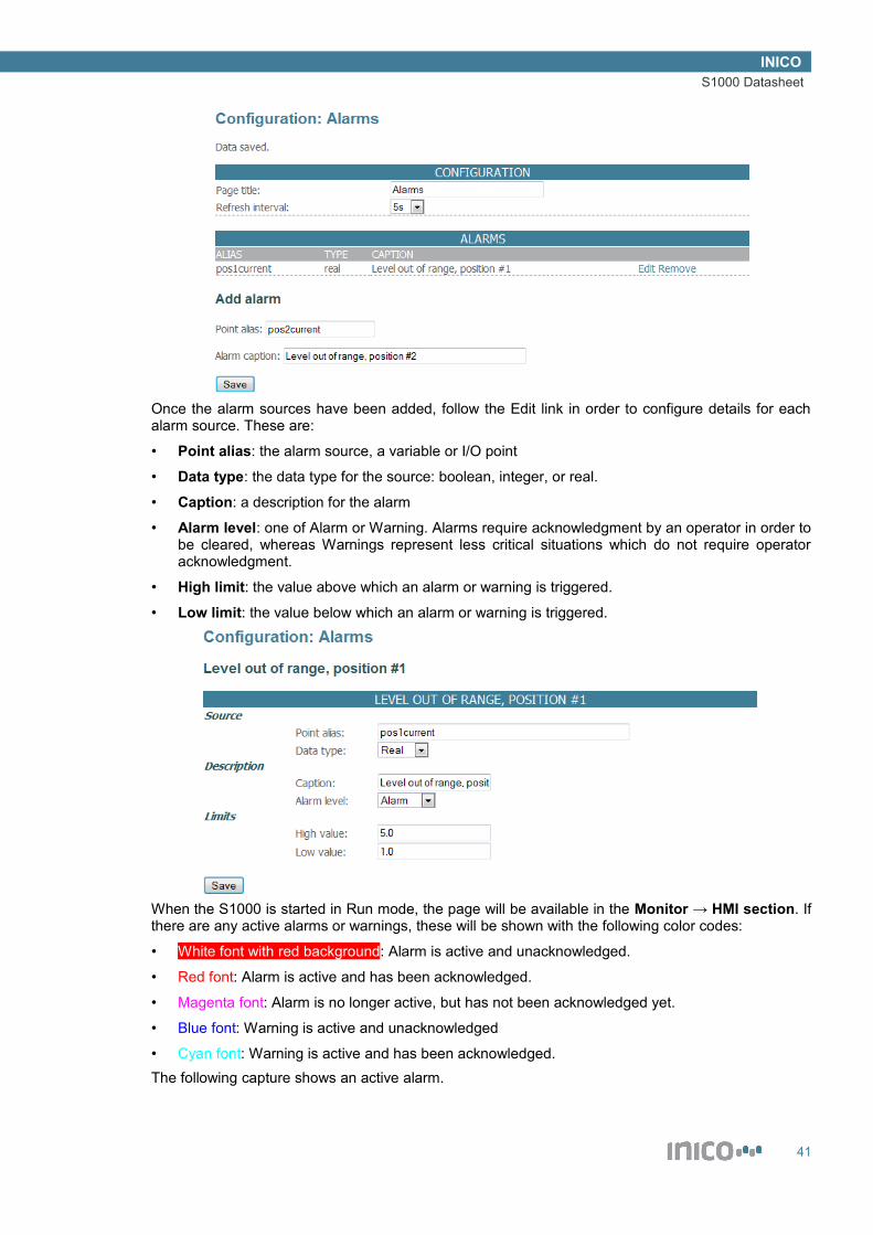
Once the alarm sources have been added, follow the Edit link in order to configure details for each alarm source. These are:
• Point alias: the alarm source, a variable or I/O point
• Data type: the data type for the source: boolean, integer, or real.
• Caption: a description for the alarm
• Alarm level: one of Alarm or Warning. Alarms require acknowledgment by an operator in order to be cleared, whereas Warnings represent less critical situations which do not require operator acknowledgment.
• High limit: the value above which an alarm or warning is triggered.
• Low limit: the value below which an alarm or warning is triggered.
When the S1000 is started in Run mode, the page will be available in the Monitor → HMI section. If there are any active alarms or warnings, these will be shown with the following color codes:
• White font with red background: Alarm is active and unacknowledged.
• Red font: Alarm is active and has been acknowledged.
• Magenta font: Alarm is no longer active, but has not been acknowledged yet.
• Blue font: Warning is active and unacknowledged
• Cyan font: Warning is active and has been acknowledged.The following capture shows an active alarm.
41

INICOS1000 Datasheet
In order to acknowledge the alarm, click anywhere on the alarm line. Enter an acknowledgment message and click on Acknowledge.
Once acknowledged, the alarm will change state.
If the alarm becomes inactive before it is acknowledged, it will be shown in magenta color. After it is acknowledged, it will disappear from the list.
The following capture shows an active Warning.
In order to acknowledge it, click on the Warning line and provide an acknowledgment message.
Unacknowledged Warnings disappear from the list when they are no longer active, regardless of whether they have been acknowledged or not.In addition to the active alarm and warning list, an Alarm Log is accessible through the HMI Pages list. The Log provides a record of the latest Alarm events, as well as any acknowledgment messages entered by operators.
42
INICOS1000 Datasheet
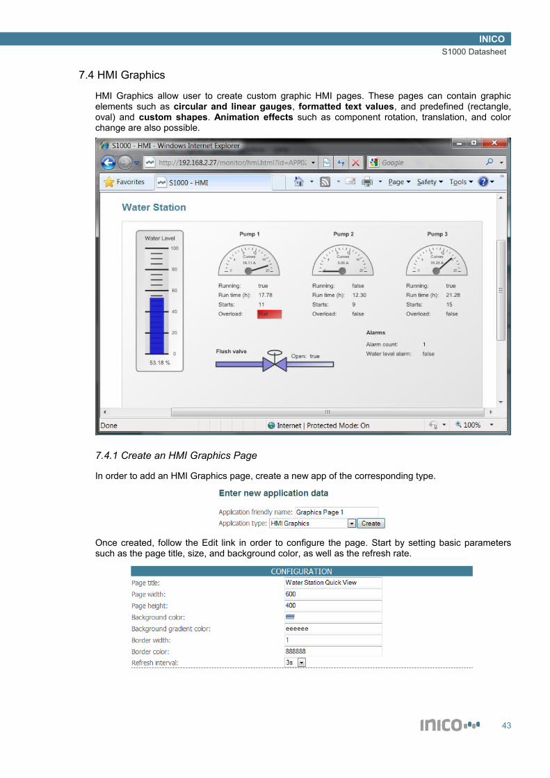
7.4 HMI Graphics
HMI Graphics allow user to create custom graphic HMI pages. These pages can contain graphic elements such as circular and linear gauges, formatted text values, and predefined (rectangle, oval) and custom shapes. Animation effects such as component rotation, translation, and color change are also possible.
7.4.1 Create an HMI Graphics Page
In order to add an HMI Graphics page, create a new app of the corresponding type.
Once created, follow the Edit link in order to configure the page. Start by setting basic parameters such as the page title, size, and background color, as well as the refresh rate.
43

INICOS1000 Datasheet
7.4.2 Colors and gradients
Colors are specified using a long-form 6 hexadecimal characters (0-9 and A-F) or a short-form 3 hexadecimal characters. In the long form, there are two characters for each the red, green, and blue components, whereas the short form uses one character for each. Some example colors are:
• Red: FF0000 or F00
• Green: 00FF00 or 0F0
• Blue: 0000FF or 00F
• Yellow: FFFF00 or F00
• White: FFFFFF or FFF
• Grey: 888888 or 888
• Black: 000000 or 000Some components allow you to define a gradient color. If used, the component will be rendered with the primary color fading into the gradient color. If you need a solid color, leave the gradient color blank.
7.4.3 Labels and Value text
A Label component allows you to display a fixed text at a specified location and with a specified format. The configuration fields for labels are:
• Component Id: an identifier for this component, useful when browsing a list of components.
• Text: the text to display in the HMI page.
• X and Y: the location of the text.
• Font, Font Size, Font Weight, and Font Color: the format of the text.A Value Text component allows you to display the value of a variable or I/O point at a specified location and with a specified format. The configuration fields for value text components are:
• Component Id: an identifier for this component, useful when browsing a list of components.
• Alias: the alias of the variable or I/O point which is the source of the text value.
• Data type: the data type of the value source, one of boolean, integer, real or string.
• X and Y: the location of the text.
• Font, Font Size, Font Weight, and Font Color: the format of the text.
7.4.4 Shapes and Toggle Shapes
A Shape component allows you to display a fixed shape at a specified location. A shape can follow a predefined pattern, such as rectangle or ellipse, or follow a custom path specification. The configuration fields for shape components are:
• Component Id: an identifier for this component, useful when browsing a list of components.
• Shape: the type of shape to render, one of rectangle, ellipse, or custom.
• Stroke color and width: the display specifications for the edge of the shape.
• Fill color: the color to fill the shape, leave blank for no fill.
• Gradient color: leave blank for solid color, or specify a color to create a gradient effect.
• X and Y: the location of the shape.
• Width/path: the width of rectangles and ellipses, or path specification for custom shapes.
• Height: the height of rectangles and ellipses, ignored for custom shapes.
44

INICOS1000 Datasheet
In order to specify a custom shape, a path must be specified using SVG format. The commands to draw lines are:
Command Name Parameters Description
M (Absolute)m (relative)
moveto (x y)+ Moves the pointer to a new location, without drawing (pen up).
L (Absolute)l (relative)
lineto (x y)+ Draws a line from the current point to the specified point (pen down).
Z orz
closepath (none) Close the current path by drawing a straight line from the current point to theinitial point.
For example, the following path generates a triangle shape:
l 50 100 l -100 0 z
For more information on SVG paths, including how to specify curves, visit http://www.w3.org/TR/SVG/paths.html.A Toggle Shape component is very similar to a shape component, but allows two states which are controlled by a variable. This allows changing the colors of a shape, and also provide rotation and translation effects, controlled by a boolean value. The configuration fields for toggle shape components are the same as for shapes, with the following fields added:
• Alias: the alias of the variable used to control the render state of the shape.
• Stroke color and width (true): the display specifications for the edge of the shape when the control variable is true.
• Fill and gradient color (true): the fill specifications of the shape when the control variable is true.
• Rotation (true): specified in degrees, the angle to rotate the shape when the control variable is true. Leave blank or specify 0 for no rotation.
• Translation (true): specified as an (x y) pair, the number of pixels to translate the shape when the control variable is true. Leave blank for no translation. E.g. use 100 -50 to translate the shape 100 pixels to the right and 50 pixels up.
7.4.5 Gauges
A Gauge component is used to display the value of a variable or I/O point using a dial or meter. Circular, semi-circular, and linear gauges are available. The configuration fields for gauge components are:
• Component Id: an identifier for this component, useful when browsing a list of components.
• Alias: the alias of the variable or I/O point which is the source of the value.
• Data type: the data type of the value source, one of integer or real.
• X and Y: the location of the text.
• Min and max value: the limits to display on the gauge.
• Major and minor ticks: the intervals at which to render ticks. Major ticks are labeled, and minor ticks are unlabeled. A rule of thumb is to define Major ticks which are about 20-25% of the total range (max value – min value), and Minor ticks which are about 20-25% of the Major tick.
• Text: a caption for the gauge.
• Units: the units to display next to the value reading. Tip: for a degree sign, use the ° symbol.
45

INICOS1000 Datasheet
• Shape: the shape of the gauge, one of circular, semi-circular, horizontal, or vertical.
• Border color and width: the specification of the gauge edge.
• Fill color and gradient: the specification of the gauge background.
• Needle color and width: the specification of the gauge needle for circular gauges, or the indicator for linear gauges.
• Needle cap fill color and gradient: the specification for the needle cap.
• X and Y: the location of the gauge.
• Width and height: the size of the gauge.
• Font, Font Size, Font Weight, and Font Color: the format of the text.
7.5 HMI Charts
HMI Charts allows creating custom trends, bar and pie charts, and other visual data representation.[TODO document charts]
46

INICOS1000 Datasheet
8 Send E-mail Reports
Within the S1000 App Library is the E-mail Reports app. This app allows you to send e-mail with a summary of variable and I/O point values. E-mail reports can be sent when a variable changes value (useful for sending alarm or warning messages), or at specified time intervals.
8.1 Create and E-mail Report app
To create an Email report app, follow instructions on the Configure → App Library → Add New Application page.
8.2 Configure SMTP Mail Server Settings
The first step is to configure the SMTP server settings. You should obtain the information required in this section from your Email system administrator. The required information is:
• SMTP server IP address
• SMTP server port (the default value is 25)
• The account name and password
8.3 Configure Destination and Subject
The next step is to enter the email addresses of the sender and recipient(s), as well as the email subject. Enter the names of the sender and recipient(s) in the double-quoted field (“Name”), and the email in between the comparison signs (<[email protected]>).For the subject field, you can enter a fixed subject text, or you can point to a string variable using the '$' symbol. In the latter case, the subject will be copied from the value of the specified variable.
8.4 Configure Timed Send Settings
You can configure the E-mail reports app to send an email at a specified time-of-day, or at specified time intervals. You may use both specifications, or neither (send emails on value changes, described later).
47

INICOS1000 Datasheet
8.5 Configure the E-mail contents
Use the alias of variables or I/O points to add values to the email body. You can edit each individual point to enable or disable it from appearing in the email body. For boolean, integer and real values, you can specify to send an email on a value change. Tip: You can use this method to control when an email is sent from within ST logic programs, by utilizing a boolean variable to trigger sending an email report.
48
INICOS1000 Datasheet
9 Log data
The Value Logger app allows you to keep a log of variable and I/O point values. Values are stored in the embedded flash memory.
NoticeThe flash memory has a maximum guaranteed life of 100.000 write cycles. You must ensure through appropriate configuration that the log isn't written too often. Writing to the flash in excess of 100.000 cycles may lead to unpredictable results.
9.1 Create a Value Logger app
To create a Value Logger app, follow instructions on the Configure → App Library → Add New Application page.
9.2 Configure Timed Save Settings
You can configure the Value Logger app to save values at a specified time-of-day, or at specified time intervals. You may use both specifications, or neither (save data on value changes, described later).
9.3 Add data points to save
Enter the aliases of all variables and I/O points that you wish to save to flash. Whenever a save operation is triggered, whether due to a time trigger or a value change trigger, all values in the list are saved simultaneously.You may edit each value source individually in order to specify whether it triggers a save operation on value change. This change may be a true/false change for boolean points, or a significant change in value for integers and reals (this means, if the value changes by more that a specified amount since the last save operation). In the example below, a save operation is triggered when the variable changes by more than 10.0 since the last save operation.
9.4 Download log to a PC
The log is available for download from the /logger/ path. For example, if the IP address of the device is 192.168.2.27, the log is available from hhtp://192.168.2.27/logger/.The log is in TSV format, or tab-separated values format. The file can be imported into MS Excel or similar software, utilizing the Tab character to separate columns.
49
INICOS1000 Datasheet
10 Technical Specifications
10.1 Electrical characteristics
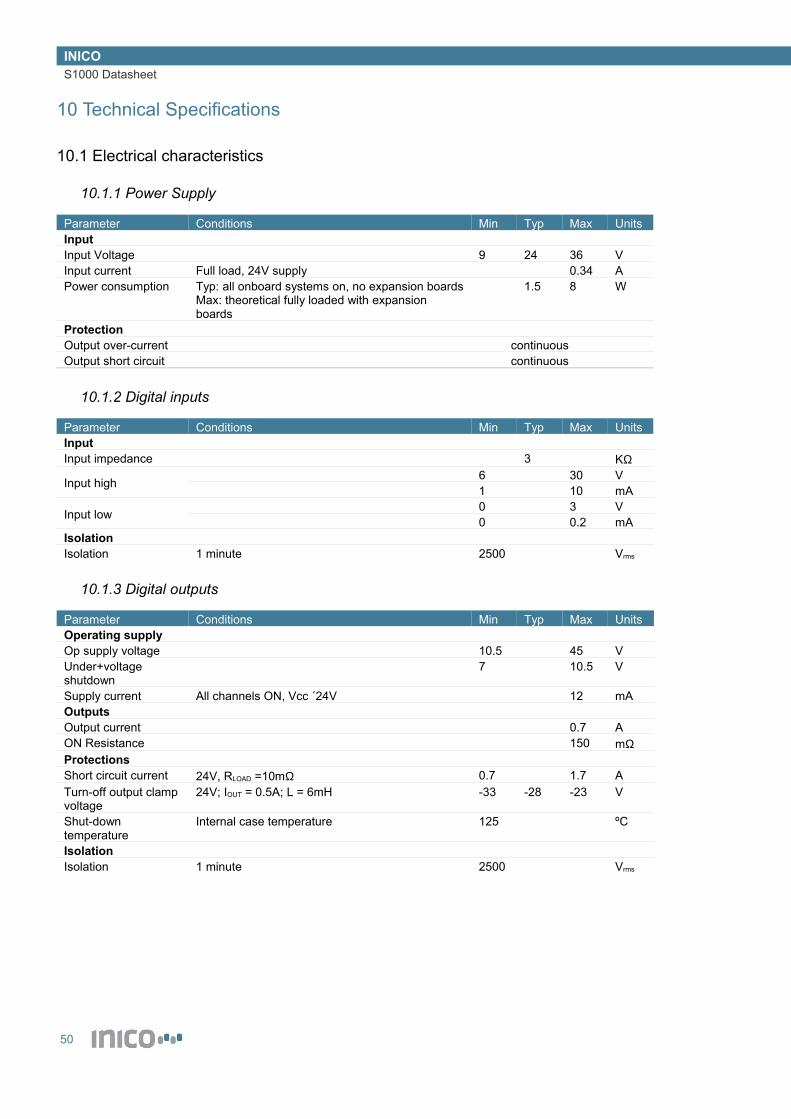
10.1.1 Power Supply
Parameter Conditions Min Typ Max UnitsInputInput Voltage 9 24 36 VInput current Full load, 24V supply 0.34 APower consumption Typ: all onboard systems on, no expansion boards
Max: theoretical fully loaded with expansion boards
1.5 8 W
ProtectionOutput over-current continuousOutput short circuit continuous
10.1.2 Digital inputs
Parameter Conditions Min Typ Max UnitsInputInput impedance 3 KΩ
Input high 6 30 V1 10 mA
Input low 0 3 V0 0.2 mA
IsolationIsolation 1 minute 2500 Vrms
10.1.3 Digital outputs
Parameter Conditions Min Typ Max UnitsOperating supplyOp supply voltage 10.5 45 VUnder+voltage shutdown
7 10.5 V
Supply current All channels ON, Vcc ´24V 12 mAOutputsOutput current 0.7 AON Resistance 150 mΩProtectionsShort circuit current 24V, RLOAD =10mΩ 0.7 1.7 ATurn-off output clamp voltage
24V; IOUT = 0.5A; L = 6mH -33 -28 -23 V
Shut-down temperature
Internal case temperature 125 ºC
IsolationIsolation 1 minute 2500 Vrms
50

INICOS1000 Datasheet
10.1.4 Analogue inputs
Parameter Conditions Min Typ Max UnitsInputs
Impedance0/4-20mA configuration 240 Ω0/1-5V configuration 1 MΩ
Voltage signal 0 5 VCurrent signal 0/4-20mA configuration 0 20.8 mAAccuracyResolution 12 bitsReference initial error 0.12 %Reference temp coefficient
10 ppm/ºC
Shunt initial error 0.1 %Shunt temp coefficient
ppm/ºC
Integral non+linearity 2 MsbIsolationIsolation 1500 Vrms
10.1.5 Serial port
Parameter Conditions Min Typ Max UnitsDriverVOUT High 5 5.4 VVOUT Low -5 -5.4 VReceiverVIN High 2.7 25 VVIN Low -2.7 -25 VProtectionsShort circuit current 35 60 mAIsolationIsolation 1500 Vrms
10.1.6 CAN port
Parameter Conditions Min Typ Max UnitsDriver
VOUT dominant CANH 2.9 3.4 4.5 VCANL 0.8 1.75 V
VOUT recessive 2 2.5 3 VVOUT standby -0.1 0.1 VProtections, maximum ratingsOutput current -20 20 mA
Bus voltage Recommended -12 12 VMaximum -27 40 V
Transient pulse -200 200 VIsolationIsolation 1500 Vrms
10.2 Environmental characteristics
Parameter Conditions Min Typ Max UnitsTemperature -40 85 ºCRelative Humidity 10 90 %
51

INICOS1000 Datasheet
10.3 Mechanical characteristics
10.3.1 Dimensions
120mm (H) x 101mm (W) x 22.5mm (D)
10.3.2 Mounting
Mounting on standard 35mm DIN Rail (IEC 60715).
10.3.3 Plug Connectors
Parameter Conditions Min Typ Max UnitsPitch 3.81 mmWire gauge 28 14 AWGTorque 1.7 Lb-inWire strip length 6 MmScrew M2
10.4 Pin Descriptions
10.4.1 Overview
10.4.2 Power supply
Pin Description+ 9-36V- 0V/Neutral
10.4.3 Digital inputs
Pin Description1-8 Input 1-8C Common
52
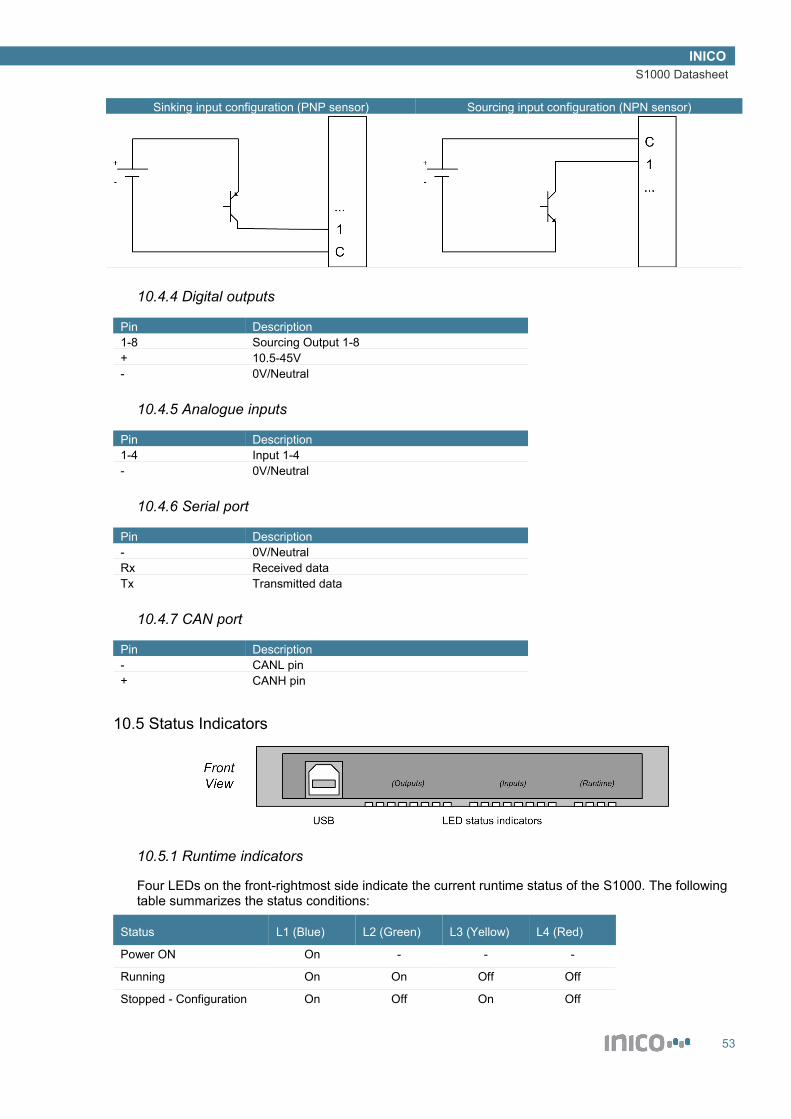
INICOS1000 Datasheet
Sinking input configuration (PNP sensor) Sourcing input configuration (NPN sensor)
10.4.4 Digital outputs
Pin Description1-8 Sourcing Output 1-8+ 10.5-45V- 0V/Neutral
10.4.5 Analogue inputs
Pin Description1-4 Input 1-4- 0V/Neutral
10.4.6 Serial port
Pin Description- 0V/NeutralRx Received dataTx Transmitted data
10.4.7 CAN port
Pin Description- CANL pin+ CANH pin
10.5 Status Indicators
10.5.1 Runtime indicators
Four LEDs on the front-rightmost side indicate the current runtime status of the S1000. The following table summarizes the status conditions:
Status L1 (Blue) L2 (Green) L3 (Yellow) L4 (Red)
Power ON On - - -
Running On On Off Off
Stopped - Configuration On Off On Off
53

INICOS1000 Datasheet
Stopped - Safe mode On Off On On
Stopped - Error On Off Off On
10.5.2 I/O indicators
Two rows of LEDs indicate the current state of digital inputs and digital outputs.The leftmost row indicates the On/Off state of the digital outputs 1-8, from left to right, in white colour.The center row indicates the On/Off state of the digital inputs 8-1, from left to right, in blue colour.
54
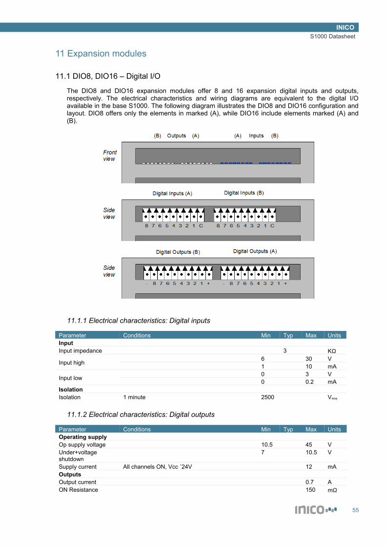
INICOS1000 Datasheet
11 Expansion modules
11.1 DIO8, DIO16 – Digital I/O
The DIO8 and DIO16 expansion modules offer 8 and 16 expansion digital inputs and outputs, respectively. The electrical characteristics and wiring diagrams are equivalent to the digital I/O available in the base S1000. The following diagram illustrates the DIO8 and DIO16 configuration and layout. DIO8 offers only the elements in marked (A), while DIO16 include elements marked (A) and (B).
11.1.1 Electrical characteristics: Digital inputs
Parameter Conditions Min Typ Max UnitsInputInput impedance 3 KΩ
Input high 6 30 V1 10 mA
Input low 0 3 V0 0.2 mA
IsolationIsolation 1 minute 2500 Vrms
11.1.2 Electrical characteristics: Digital outputs
Parameter Conditions Min Typ Max UnitsOperating supplyOp supply voltage 10.5 45 VUnder+voltage shutdown
7 10.5 V
Supply current All channels ON, Vcc ´24V 12 mAOutputsOutput current 0.7 AON Resistance 150 mΩ
55
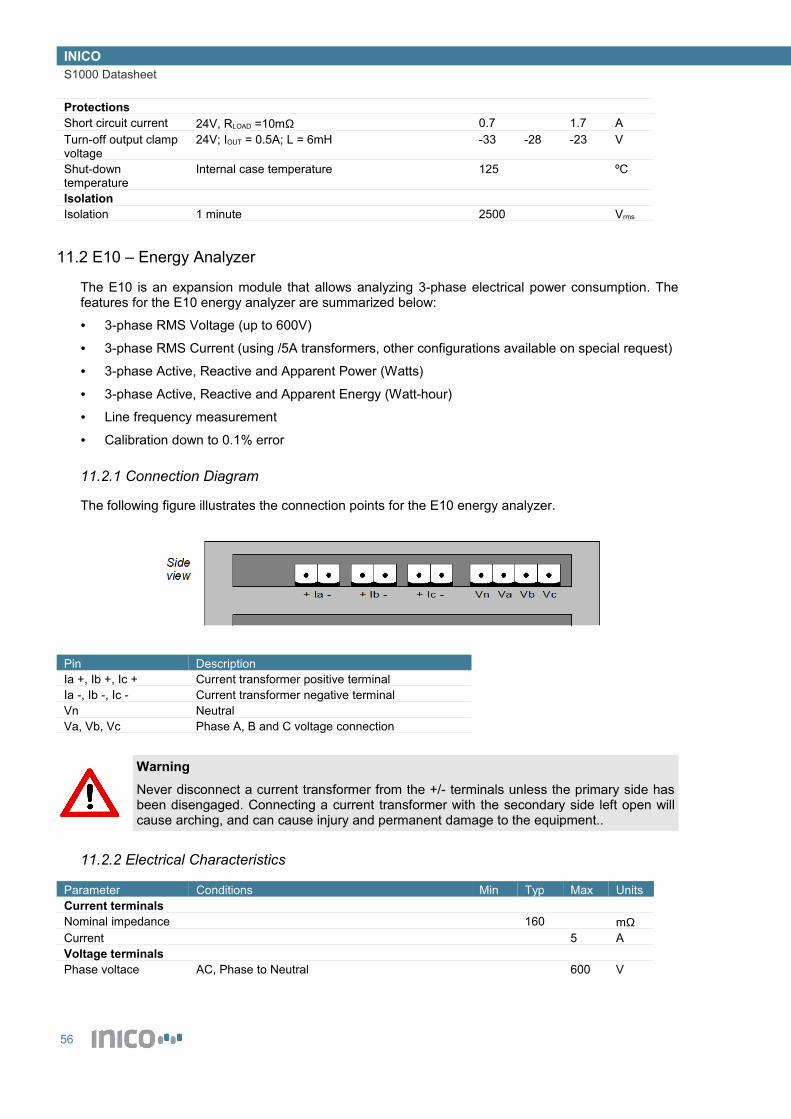
INICOS1000 Datasheet
ProtectionsShort circuit current 24V, RLOAD =10mΩ 0.7 1.7 ATurn-off output clamp voltage
24V; IOUT = 0.5A; L = 6mH -33 -28 -23 V
Shut-down temperature
Internal case temperature 125 ºC
IsolationIsolation 1 minute 2500 Vrms
11.2 E10 – Energy Analyzer
The E10 is an expansion module that allows analyzing 3-phase electrical power consumption. The features for the E10 energy analyzer are summarized below:
• 3-phase RMS Voltage (up to 600V)
• 3-phase RMS Current (using /5A transformers, other configurations available on special request)
• 3-phase Active, Reactive and Apparent Power (Watts)
• 3-phase Active, Reactive and Apparent Energy (Watt-hour)
• Line frequency measurement
• Calibration down to 0.1% error
11.2.1 Connection Diagram
The following figure illustrates the connection points for the E10 energy analyzer.
Pin DescriptionIa +, Ib +, Ic + Current transformer positive terminalIa -, Ib -, Ic - Current transformer negative terminalVn NeutralVa, Vb, Vc Phase A, B and C voltage connection
WarningNever disconnect a current transformer from the +/- terminals unless the primary side has been disengaged. Connecting a current transformer with the secondary side left open will cause arching, and can cause injury and permanent damage to the equipment..
11.2.2 Electrical Characteristics
Parameter Conditions Min Typ Max UnitsCurrent terminalsNominal impedance 160 mΩCurrent 5 AVoltage terminalsPhase voltace AC, Phase to Neutral 600 V
56

INICOS1000 Datasheet
11.3 W1-Z – Wireless Module, Zigbee PRO
The W1-Z module adds wireless networking to the S1000. It uses the ZigBee PRO protocol for communications. For more information on features and configuration, see the Wireless I/O section of this manual.
Parameter Conditions Min Typ Max UnitsRadioFrequency Band 2.4 2.48 MHzNumber of Channels 16Channel spacing 5 MHzData rate 250 KbpsTX power -17 3 dBmRX sensitivity PER = 1% -101 dBmAntenna terminalAntenna impedance RP-SMA connector 50 ΩOperating conditionsTemp. Range -40 to 85 operational with minor degradation of
clock stability-20 70 ºC
Rel. Humidity 80 %
11.3.1 FCC Certification
This product has been certified for use in the United States of America.
Contains FCC ID: U6TZIGBIT-B0
The enclosed device complies with Part 15 of the FCC Rules. Operation is subject to the following two conditions: (i.) this device may not cause harmful interference and (ii.) this device must accept any interference received, including interference that may cause undesired operation.
11.3.2 Industry Canada Certification
This product has been certified for use in Canada.
Certification number IC: 7036A-ZIGBITB0
Manufacturer's Name ZIGBIT
Model Name ATZB-24-B0
11.3.3 CE Marking
This product has been certified for use in the European Union.
57
INICOS1000 Datasheet
12 Compliance and Certifications
12.1 Electro-magnetic compatibility (EMC)
The S1000 complies with the following standards and codes:
• FCC Part 15.107 Class A Conducted emissions
• FCC Part 15.109 Class A Radiated emissions
• ICES-003 Issue 4 Class A Radiated and conducted emissions
• CISPR 22 : 2003 / EN 55022 : 1998 Class A Radiated and conducted emissions
• EN 61000-6-1 : 2001o EN 61000-4-2 ESD Direct
o EN 61000-4-2 ESD indirect
o EN 61000-4-3 Radiated Immunity
o EN 61000-4-4 EFT
o EN 61000-4-6 CS induced RF field
o EN 61000-4-8 Power Freq. Magnetic field
12.2 Safety standards
This device is not yet certified for safety standards such as UL, CSA or TÜV. Please contact Inico Technologies for further information on saftey certification.
12.3 Hazardous locations
This device is not yet certified for use in hazardous locations. Please contact Inico Technologies for further information on HazLoc certification.
WarningExplosion hazard, do not install in potentially explosive atmospheres.
12.4 IEC 61131-3 Compliance
This system complies with the requirements of IEC 61131-3 for the following language features:
12.4.1 Common elements
Table number
Feature number Feature description Notes
1 1 Required character set1 2 Lower case characters1 4a Dollar sign ($)2 1 Identifiers using upper case and numbers2 2 Identifiers using upper and lower case, numbers,
embedded underlines2 3 Identifiers using upper and lower case, numbers,
leading or embedded underlines3 1 Comments4 1 Integer literals4 2 Real literals
58

INICOS1000 Datasheet
4 3 Real literals with exponents4 8 Boolean FALSE and TRUE5 1 String literals6 2 Dollar sign6 3 Single quote6 4 Line feed6 5 Newline6 6 Form feed6 7 Carriage return6 8 Tab10 1 BOOL (Boolean) data type10 3 INT (integer) data type Implemented as 32-bit double int10 4 DINT (double integer) data type10 10 REAL (floating point) data type10 16 STRING (variable-length character string) data type13 Default initial values: BOOL := FALSE; INT, DINT :=
0; REAL := 0.0; STRING := ‘’;16 VAR_GLOBAL global variable declarations17 5 Automatic memory allocation of symbolic variables Multiple comma-separated
identifiers not allowed18 5 Initialization of symbolic variables22 1 Type conversion functions: BOOL_TO_STR,
INT_TO_STR, INT_TO_HEX, REAL_TO_STR, STR_TO_BOOL, STR_TO_INT, STR_TO_REAL
See 5.6.4
23 1 ASB function23 2 SQRT function24 12 ADD arithmetic function + symbol24 13 MUL arithmetic function * symbol24 14 SUB arithmetic function - symbol24 15 DIV arithmetic function / symbol24 16 MOD arithmetic function24 17 EXPT arithmetic function ** symbol26 5 AND bitwise Boolean function26 6 OR bitwise Boolean function26 7 XOR bitwise Boolean function26 8 NOT bitwise Boolean function28 5 GT comparison function > symbol28 6 GE comparison function >= symbol28 7 EQ comparison function = symbol28 8 LE comparison function <= symbol28 9 LT comparison function < symbol28 10 NE comparison function <> symbol29 1 LEN string function Use STR_LEN keyword29 2 LEFT string function Use STR_LEFT keyword29 3 RIGHT string function Use STR_RIGHT keyword29 4 MID string function Use STR_MID keyword29 5 CONCAT string function Use STR_CONCAT keyword29 9 FIND string function Use STR_FIND keyword
12.4.2 ST language elements
Table number
Feature number Feature description Notes
55 1 Parenthization55 2 Function evaluation55 3 Exponentiation55 4 Negation55 5 Complement55 6 Multiply
59

INICOS1000 Datasheet
55 7 Divide55 8 Modulo55 9 Add55 10 Subtract55 11 Comparison55 12 Equality55 13 Inequality55 14 Boolean AND (& symbol)55 15 Boolean AND (AND symbol)55 16 XOR55 17 OR56 1 Assignment statement56 3 RETURN statement56 4 IF statement56 6 FOR statement56 7 WHILE statement56 8 REPEAT statement56 10 Empty statement
12.4.3 Implementation-dependent parameters
The following table lists the parameters adopted by the S1000 implementation, as required by the IEC 61131-3 standard Annex D.
Clause Parameter Value2.1.1 $ or “currency” sign $2.1.2 Maximum length of identifiers 392.1.5 Maximum comment length Unlimited2.4.2 Initial value of inputs As per actual input
scanner2.4.3 Maximum number of variables per declaration One2.5.3 Program size limitation Subject to available
system memory3.3.1 Maximum length of expressions Unlimited3.3.2 Maximum length of expressions Unlimited3.3.2.3 Maximum number of CASE selections Not implemented3.3.2.4 Value of control variable upon termination of FOR loop Final value + Step
60

INICOS1000 Datasheet
13 Revision History
Revision Date Comments0.1 16-March-2009 First version.1.0 29-May-2009 First release. Included indicator section.1.1 09-Fe-2009 Added expansion IO modules: DIO16, E101.2 05-Ma-2010 Major edit, all sections modified.
61


