43
Sa vz. 58 Sporter Rifle Instructions Manual

Sa vz. 58 Sporter RifleInstructions Manual

Content:
Part I. Description of the design of the Sa vz. 58 Sporter Rifle.......... 3Chapter 1 General 1.Purposeandpropertiesoftherifle 2.Characteristicsoftherifle 3. Markings
Chapter 2 Description of the main parts of the rifle 1. Barrel 2. Receiver 3. Bolt 4. Trigger mechanism 5. Stock and handguards
Chapter 3 Accessories 1. Magazines 2. Magazine pouch 3. Sling 4. Cleaning kit 5. Cheek piece 6. Recoil pad 7. CD
Chapter 4 Ammunition 1. Types of ammunition 2. Loading of magazines
Part II. Functioning of the rifle and troubleshooting, storage, inspections, maintenance and repairs.................................... 21Chapter 1 Functioning of the parts and mechanisms of the rifle 1.Preparingtherifleforshooting 2. Functioning of the parts
Chapter 2 Troubleshooting 1. General rules for preventing malfunctions 2. Typical malfunctions, their causes and solutions
Chapter 3 Storage 1.Storingtherifle
Chapter 4 Inspecting the rifle 1.Principlesofinspectingtherifle 2. Disassembly 3. Assembly
Chapter 5 Maintenance 1.Principlesformaintainingtherifle 2. Cleaning and preserving agents 3.Procedureforcleaningandpreservingtherifle
Chapter 6 Repairs
Part III. Zeroing of the rifle................................................................... 40
2.
PARTI.DescriptionofthedesignoftheSavz.58SporterRifle
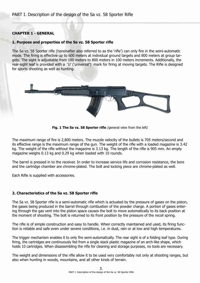
CHAPTER 1 - GENERAL 1. Purpose and properties of the Sa vz. 58 Sporter rifle TheSavz.58Sporterrifle(hereinafteralsoreferredtoasthe‘rifle’)canonlyfireinthesemi-automaticmode.Thefiringiseffectiveupto600metersatindividualgroundtargetsand800metersatgrouptar-gets. The sight is adjustable from 100 meters to 800 meters in 100 meters increments. Additionally, the rear-sightleafisprovidedwitha‘U’(‘universal’)markforfiringatmovingtargets.TheRifleisdesignedforsportsshootingaswellashunting.
Themaximumrangeoffireis2,800meters.Themuzzlevelocityofthebulletsis705meters/secondanditseffectiverangeisthemaximumrangeofthegun.Theweightoftheriflewithaloadedmagazineis3.42kg.Theweightoftheriflewithoutthemagazineis3.13kg.Thelengthoftherifleis905mm.Anemptymagazineweighs0.13kgand0.29kgwhenloadedwith10rounds.
The barrel is pressed in to the receiver. In order to increase service life and corrosion resistance, the bore andthecartridgechamberarechrome-plated.Theboltandlockingpiecearechrome-platedaswell.
EachRifleissuppliedwithaccessories.
2. Characteristics of the Sa vz. 58 Sporter rifle
TheSavz.58Sporterrifleisasemi-automaticriflewhichisactuatedbythepressureofgasesonthepiston,thegasesbeingproducedinthebarrelthroughcombustionofthepowdercharge.Aportionofgasesenter-ing through the gas vent into the piston space causes the bolt to move automatically to its back position at the moment of shooting. The bolt is returned to its front position by the pressure of the recoil spring.
Therifleisofsimpleconstructionandeasytohandle.Whencorrectlymaintainedandused,itsfiringfunc-tionisreliableandsafeevenundersevereconditions,i.e.indust,rainoratlowandhightemperatures. Thetriggermechanismenablesittoonlyfiresemi-automatically.Therearsightisofafoldingleaftype.Duringfiring,thecartridgesarecontinuouslyfedfromasinglestackplasticmagazineofanarch-likeshape,whichholds10cartridges.Whendisassemblingtherifleforcleaningandstoragepurposes,notoolsarenecessary.
Theweightanddimensionsoftherifleallowittobeusedverycomfortablynotonlyatshootingranges,butalsowhenhuntinginwoods,mountains,andallotherkindsofterrain.
3.
Fig. 1 The Sa vz. 58 Sporter rifle/generalviewfromtheleft/
PARTI.DescriptionofthedesignoftheSavz.58SporterRifle
3. Marking and numbering of the rifle
Eachrifleismarkedwiththeserialnumber,nameoftherifle,caliber,countryoforiginandcodemarkoftheU.S.importer.
CHAPTER 2 - DESCRIPTION OF THE MAIN PARTS OF THE RIFLE
TheSavz.58Sporterriflehasthefollowingmainparts
1. Barrel Thebarrel1isintendedtodirecttheprojectile.Thebarrelisprovidedwithaborewithfourgrooveswhichproducesthefourfieldsoftherifling.Thebarrelboretwistproducesarighthandhelixwithaconstantlead(thetwistoftherifling)of240mm,whichimpartsarotarymotiontotheprojectile.Theprojectilerotationensuresthattheprojectileinthecourseofitsflightthroughtheairdoesnotchangeitspositionwithregardtoitslongitudinalaxis(trajectory)andisthusstabilized.Themuzzleisprovidedwithaninnerroundingofthetwistwiththeaimofexcludinganydamagetothetwist.Thediameteroftheboremeasuredbetweentwooppositefieldsisknownasthecaliber.ThecaliberoftheSavz.58Sporterrifleis7.62mm.Inordertoimproveservicelife(toreducewear)andcorrosionresistance,theboreischrome-plated.Thebarrelispressedintothereceiverandlockedwithapin.
Intherearpartofthebore,thetwistpassesintoasmoothcartridgechamberwhoseshapeanddimen-sionscorrespondtothecartridgeincal.7.62mm.Thecartridgechamberpassesintotherifling(therifledpartofthebore)viathetransitionconewhichenablestheprojectiletograduallycutintothegrooves.Thecartridgechamberischrome-platedaswell.
4.
5S3
2
16S
4
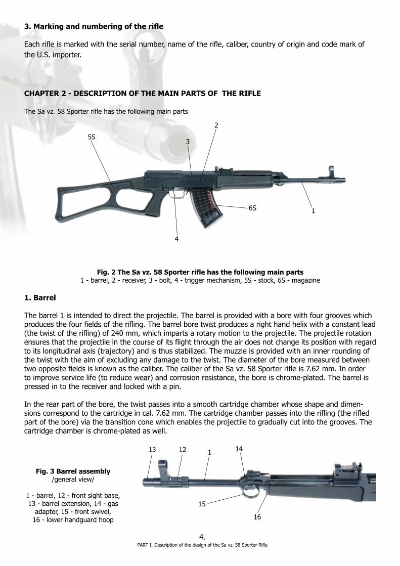
Fig. 2 The Sa vz. 58 Sporter rifle has the following main parts1-barrel,2-receiver,3-bolt,4-triggermechanism,5S-stock,6S-magazine
12 1 1413
15
16
Fig. 3 Barrel assembly/generalview/
1-barrel,12-frontsightbase,13-barrelextension,14-gasadapter,15-frontswivel,16-lowerhandguardhoop
PARTI.DescriptionofthedesignoftheSavz.58SporterRifle

The external cylindrical surface of the barrel is stepped four times. Near the muzzle, on the barrel, is the pressedfrontsightbase12whichislockedbytwopins121and122inordertopreventturning(Fig.4).Infrontofthefrontsightbaseisthebarrelextension13attachedpermanentlytothemuzzle.Bar-relextension13isweldedtothefrontsightbase12bottomplate.
Barrelextension13(Fig.5)isofacylindricalshapeandisstrengthenedinitsrearpart.Insidethestrengthenedrearpartisthethreadusedforscrewingthebarrelextensionontothemuzzle.
Approximatelyatthehalfwaypointofthebarrellengthisaninsertedgas adapter14(Fig.6)whichislocked by means of the pin. In the upper part of the gas adapter is a cavity that forms the gas cylinder.Aportionofthepowdergasesisconveyedfromthebarrelthroughthegasadaptertothegascylinder.Thepowdergasesflowtothegascylinderthroughthegaschannelwhichconnectstheborewiththegascylinderspace.Atthehalfwaypointofthelengthofthelowerpartofthegascylinderwall,twoopeningspointingobliquelydownwardalongbothsidesofthebarrelaredrilled.Thepowdergasesescapefromthegascylinderthroughthoseopeningsafteraroundhasbeenfired;thepiston,movingbackwards,haspassedmorethanhalfthegascylinderlength.Ontheleft-handsideofthegasadapteristheeye(thimble)forthefrontswivel15(Fig.3).Bothsidesofthegascylinderfrontpartareprovidedwithlugswithgroovesintowhichtheupperhandguardjackettipsaretoshift.Therearpartofthegasadapterformsacatchbywhichthelowerbarrelguardfronthoopisheld.Halfofthegascylinderupperwalliscutoffforshiftinginandoutof the piston.
Fig 5. Barrel extension/sideview/13-barrelextension
5.PARTI.DescriptionofthedesignoftheSavz.58SporterRifle
Fig. 4 Front sight base/sectionalview/11-frontsight,111-frontsightpin,121and122-frontsightbasepins
11 111
122121
13

Piston141(Fig.7)transmitsthekineticenergyofaportionofthepowdergasesproducedbythecombus-tionofthepowderchargeinthebarreltotheboltcarrier.Thefrontpartofthepistonhasacylindricalheadwithacircumferentialgrooveforbetterpackingofgasesinthegascylinderandfordepositionofburntpowderremainders.Therearpartofthepistonisthickenedandformsaguideforpistonspring142withitsoneendleaningagainstthefaceoftherear-sightbaserecessandwithitsotherendagainstthecollarofthecylindricalreinforcementwhich,togetherwiththestopintherear-sightbaserecess,limitsthepistonforwardmotion.Thetransitionofthecylindricalreinforcementintotheguidepartofthepistonisofaconi-calshape;thisconicalsurfacelimitspistonmotionbybearingagainstthecorrespondingsurfaceoftherearsight base. The piston spring causes the piston to return from the rear position once again to the starting position(i.e.tothefrontposition).
Front sight11(Fig.4)togetherwithrearsight21formthesightsoftherifleandareusedforaimingtherifle.Thefrontsightisofacylindricalshape,providedwithathreadinitsbottompart,longitudinallycutandopened.Itisscrewedintothefrontsightpin111andthefrontsightthreadpartenablesittobeadjustedforheight.Afterscrewingthefrontsightintothefront-sightpin,theopenedpartsprings,thuspreventing the front sight from turning spontaneously. Front sight pin111isplacedcrosswiseintheupperpartofthefrontsightholderandisintendedforscrewinginthefrontsightandforitssideadjustmentwhenzeroingin.
Fig. 6 Gas adapter/sectionalview/14-gasadapter,141-piston
142
141
Fig. 7 Piston with spring 141-piston,142-pistonspring,143-pistonstop
6.PARTI.DescriptionofthedesignoftheSavz.58SporterRifle
14
141
143

Thefrontsightholderisshapedinitsupperpartinordertoformacolumnandendswithfront-sightcoverwingsensuringthatthefrontsightisprotectedagainstdamage.Inthefacewallofthefront-sightbaseisahalf-roundrecesswhichuncoversthemiddlepartofthefront-sightpin.Onthefront-sightpinandontherecesswallaretwosightinggaugemarksthat,ifoppositeeachother,indicatethecorrectsidepositionofthe front sight. The correct position for the height of the front sight is locked by a drop of lacquer on the frontedgeofthefrontsightandthefront-sightbase.
2. The receiver assembly
Thereceiver(Fig.8)isoneofthemainpartsoftherifle;itjoinstheotherriflepartstogetherasawholeand guides the bolt.
Itconsistsofthefollowingmainparts:receiverproper2,rearsight21,ejector22,boltcatch23,magazinecatch24,receivercoverpinsafetypin25,receivercoverpin26andlowerhandguardpin27.
Onbothsidesintherectangularrecessofthereceiverareguidinggrooves(a,b)alongwhichtheboltcar-rierandtheboltmove.Inthefrontthickenedpartofthebarsbarerecessesinwhichthelockinglugsofthelockingpiecesnapwhenlockingthebolt.Thefrontwallbetweentheguidebarsischamfered,thusformingtheramp(c)whichenablesthecartridgetobeeasilypushedintothecartridgechamber.Thebar-relisinsertedintothefrontpartofthereceiver.Inthemiddleofthereceiverisbridge(d)whichdividestheentireinnerspaceofthereceiverintotwoparts:thefrontmagazinewellandtherearrecessforseatingthetriggermechanism.Inthefrontmagazinewallisalugwhichengagesinthecorrespondingrecessintheupperpartofthefrontedgeofthereceivermagazinewell.
Rearsight(Fig.9)enablestheneededanglesofthetan-gentelevationtobeset;therearsightisfixedintherearsightbase.Rearsight21(Fig.10)isassembledtogetherwithrearsightslide211,rearsightplunger212withspring 213 and rear sight feather 214.
7.PARTI.DescriptionofthedesignoftheSavz.58SporterRifle
25
2621
23
22
Fig. 8 The receiver assembly/topview/2-receiver,21-rearsight,22-ejector,23-boltcatch,25-receivercoverpin,26-receivercoverpinsafetypin,
a-guidinggrooves,b-lockinglugs,c-ramp,d-bridge
b ac
d
212211
Fig. 9 Rear sight assembly21-rearsight,211-slide,212-rearsightplunger,
214-rearsightfeather,a-rearsightbase
2
21214 a

8.PARTI.DescriptionofthedesignoftheSavz.58SporterRifle
The rear sight baseformsonepiecewiththereceiver.Thesidesofthefrontelevatedpartareprovidedwithopeningsfortherearsightpins.Thesidewallsoftherearsightbaseformramps.Betweenthesidewallsisarecessforshiftingintherearsightfeather.Intherearpartoftherecessisadimpleforfixingtherear sight feather.
Rear sight21isintendedforsettingtheslideinordertocorrespondtoanappropriaterange;itisofaplate-likeshape.Therearepins(a),onitsfrontnarrowedpart,bywhichtheleafisswinginglymountedinthe openings of the rear sight base. The rear sight leaf is inserted into the base by means of the rear sight feather.AttherearendoftheleafistherectangularVnotch(b).Onthetopendoftheleafaregaugelineswithfiguresfrom1to8(theoddfiguresareontherightandtheevenfiguresontheleft)whichindicatetherangeoffireinhundredsofmeters.Therearsightcanconsequentlybesetatadistancefrom100metersto800meters.Additionally,theleft-handsideoftherearsightleafisprovidedwithagaugelinemarkedU,‘universal’,whichindicatesarangeoffireupto300meters.TheUsettingcanbeengagedbyshiftingtheslide211totherearpositionuntilitstops.Ontheright-handsideoftheleafare9notchespointingobliquelydownwards.Therearsightplunger212lugengagesthesenotches,bywhichtheslideislockedinthesetposition.Thedimpleinthefrontnarrowedpartoftherearsightleafisdesignedforthepointedendofthefrontsightspannerwhichisusedfordisassemblingtherearsight.
Slide 211 of the rear sight is slipped over the rear sight leaf. In the middle part of the slide is a rectangular windowthroughwhichtheslidecanbeslippedovertherearsightleaf.Theinsidecylindricalcavityintheslideisintendedforbearingplunger212withspring213.Thebottomsideoftheslideleansonandmovesalongthesightramps.Theright-handsidesurfaceofthesteppedpartoftheslideisannularlyknurledandisintendedtoserveasarestforthefingerwhendepressingtheplungerforsettingtherangeoffire.Theslide is held in the desired position by the plunger.
Rear sight plunger 212 locks the slide in the set position by snapping the chamfered lug of the plunger intheappropriatenotchontheright-handedgeoftherearsightleaf.Theplungerlugisheldinthenotchontherearsightleafbythepressureoftheplungerspring.Thespringisseatedinthecavityoftheslide;withitsoneendleaningontheslideandwiththeotherendagainstthelateralsideoftheplunger.Theplungerisprovidedwithadeeprecesswhosesurfacelockstheplungerinasteadypositionontherearsightleaf;thisflatrecessguidestheplungeralongthebottomsideoftheleaf.Theplungermaybedis-placed after pressing the knurled lateral surface.
211
21
213
212
214
Fig. 10 Rear sight/explodedview/21-rearsight,211-slide,212-rearsightplunger,213-rearsightplungerspring,214-rearsightfeather,
a-sightpins,b-sightnotch
a
b
Rear sight feather214withitsfrontendpressesthebottomsideoftherearsightinfrontoftheleafpinssothattheslideisconstantlyforceddowntotherearsightramps.Therearsightfeatherisshiftedwithitsrearendintothegrooveintherearsightbasetherebypreventingverticalmotionoftherearendofthefeather.Whenthefeatherisshiftedin,thestampeddimpleattheendofthefeatherengagesthedimpleintherearsightbase,whichpreventsforwarddisplacementofthefeatherwhentheleafisbeingput on.
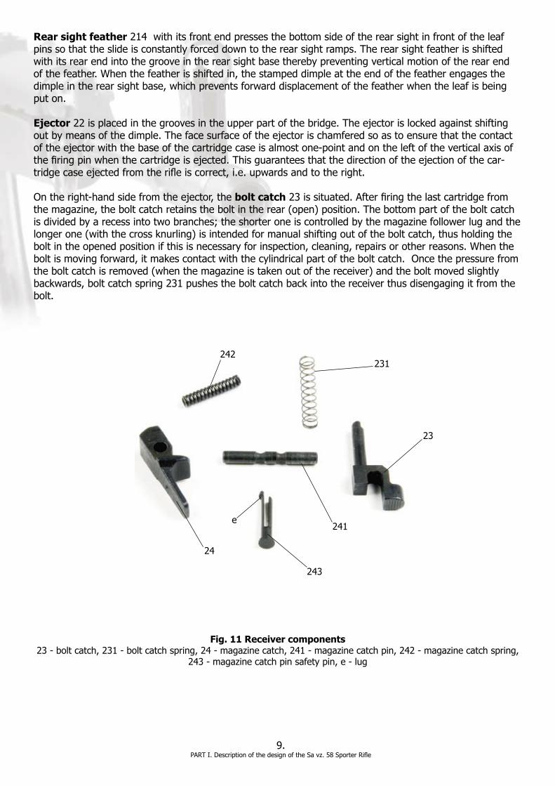
Ejector 22 is placed in the grooves in the upper part of the bridge. The ejector is locked against shifting out by means of the dimple. The face surface of the ejector is chamfered so as to ensure that the contact oftheejectorwiththebaseofthecartridgecaseisalmostone-pointandontheleftoftheverticalaxisofthefiringpinwhenthecartridgeisejected.Thisguaranteesthatthedirectionoftheejectionofthecar-tridgecaseejectedfromtherifleiscorrect,i.e.upwardsandtotheright.
Ontheright-handsidefromtheejector,thebolt catch23issituated.Afterfiringthelastcartridgefromthemagazine,theboltcatchretainstheboltintherear(open)position.Thebottompartoftheboltcatchisdividedbyarecessintotwobranches;theshorteroneiscontrolledbythemagazinefollowerlugandthelongerone(withthecrossknurling)isintendedformanualshiftingoutoftheboltcatch,thusholdingtheboltintheopenedpositionifthisisnecessaryforinspection,cleaning,repairsorotherreasons.Whentheboltismovingforward,itmakescontactwiththecylindricalpartoftheboltcatch.Oncethepressurefromtheboltcatchisremoved(whenthemagazineistakenoutofthereceiver)andtheboltmovedslightlybackwards,boltcatchspring231pushestheboltcatchbackintothereceiverthusdisengagingitfromthebolt.
9.PARTI.DescriptionofthedesignoftheSavz.58SporterRifle
231
23
241
243
24
242
Fig. 11 Receiver components23-boltcatch,231-boltcatchspring,24-magazinecatch,241-magazinecatchpin,242-magazinecatchspring,
243-magazinecatchpinsafetypin,e-lug
e

Frombelowontheleft-handsideoftheejector,onpin241istheswinginglyseatedmagazinecatch24whichkeepsthemagazineinsertedinthereceiver,thuspreventingitfromfallingout.Themagazinecatchisprovidedwithalugwhich,throughactuationofspring242,snapsinbehindthelugontherearedgenearthemagazinefeedlips.Withitsoneendthespringisseatedinthepocketofthereceiverbridgewhilethe other end bears on the cylindrical recess of the magazine catch.
Pin 241 is common for both the magazine catch and the bolt catch. It is locked against loosening by safe-typin243whichislongitudinallycutupandopened.Atthelongerendofthecut-uppartisexternallug(e)whichsnapsinbehindtheedgeoftherecessintheupperwallofthereceiverbridge.Thesafetypinwithitscylindricalpartfitsintothecircumferentialgrooveonpin241.
Inthebottomofthereceiveraretworectangularopenings.Thetriggerpassesintothefirstonewhiletheotherisdesignedforseatingtheshapednutofthegripscrew.Trigger guard 28 is riveted to the bottom ofthereceiver.Therearwallofthereceiverisprovidedwithathreadforfixingthestocktothereceiver’srearfaceandadditionallywithagrooveforfixingthereturnmechanism.Thepositionofthesteppedreturnmechanismislockedbyreceivercoverpin25(Fig.8)whichiskeptinpositionbytheforceofreceivercoverpinsafetypin26whichpressesagainstthetwocircumferentialgroovesofthereceivercoverpin.Receivercoverpinsafetypin26ismountedverticallyinthewallofthereceiverrearright-handcornerandis pushed by the rear arm of the trigger mechanism feather.
3. Bolt assembly
Theboltmakespossibletheactionoftherifle;pushingthecartridgesfromthemagazineandinsertingthemintothecartridgechamber;lockingthecartridgechamberatthemomentoffiring,ignitingthecar-tridgeprimer,pullingoutandejectingthefiredcartridgecase.
Theboltassemblyhasthefollowingparts:theboltcarrier,bolt,lockingpiece,andstriker.
Bolt carrier35(Fig.13)actuatesthebolt,thelockingpieceandthedisconnector.Thefrontwalloftheboltcarrierisprovidedwitharecessagainstwhichthebottompartofthepistonstrikesatthemomentoffiring.Ontheright-handsideoftheboltcarrieriscockingleverawhichisdesignedforhand-operatedcockingofthebolt.Bothsidesoftheboltcarrierareprovidedwithguidegrooves(b)whichareinterruptedataboutthehalfwaypointbyarecesswhoseshapecorrespondstothecorrespondinglugsinthereceiver.Thisrecessisintendedforinsertingtheboltcarrierinthereceiverandfortakingitoutagain.Therearwalloftheboltcarrierisprovidedwiththreelongitudinalopenings.Thetopopeningismadeinordertohousethereturnspringwhiletheothertwoopeningsaredesignedtolowertheweightoftheboltcarrier.
10.PARTI.DescriptionofthedesignoftheSavz.58SporterRifle
Fig. 12 Bolt catch and magazine catch/sectionalview/23-boltcatch,241-magazinecatchpin,24-magazinecatch
23241
24

Thebottompartoftheboltcarrierhasarecesswhichisdividedintotwopartsbypartitionwall(c).Thepartitionwalltogetherwithunlockingtip(d)controlthemotionofthelockingpiece.Theunlockingtipformedinthefrontpartpullsthelockingpiecefromthelockedposition.Theunlocking-tipbottomsurfaceformsаguideforthebolt.Boltcarriershaft(e)providedwithanopeningforthestrikerissituatedinthebottomrearpartoftheboltcarrier.Whendisassemblingandassemblingthebolt,thestrikerislockedagainstfalling-outbyalugwhichprojectsfromtheleft-handsideintotheopeningforthestriker.Boltcarriersideplate(f)actuatesthedisconnector.
Locking piece36(Fig.13)ensurestheproperlockingofthecartridgechamber.Itisofhorse-shoeshape;botharmsofthelockingpiecepassattheendsintojoints(m)bywhichthelockingpieceisswinginglycar-riedintheboltbearings.Inthefrontbottompartofthelockingpiecearesituatedlockinglugs(n)which,whenthelockingpieceisinalockedposition,transmitthepressureproducedatthemomentoffiringtothe receiver.
Striker37(Fig.13)strikesagainstthefiringpin.Itisofahollowcylindershapeclosedatitsfrontendbyasmoothfrontwallcomingintocontactwiththefiringpin.Therearopenendhasaheadprovidedwithgroovesbywhichthestrikerisguidedalongthebarsinthereceiver.Thestrikerheadiselongateddown-wards,thusforminganose(o).Thecylindricalpartofthestrikerisreliefedalongtheperipherybymeansofsixlongitudinalgrooves.Thegrooveontheleft-handsideofthestrikerisclosedonitsfrontsideandiselongatedbackwardsasfarasthestrikerhead.Thegrooveisguidefortheprojectionoftheboltcarrier.Theprojectionpreventsthestrikerfromfallingoutoftheboltcarrier.Thisclosedgrooveisjoinedwiththeneighboringlongitudinalgroovebymeansofacrossgroovewhichenablestheprojectionoftheboltcar-riertopasstotheclosedgroove.Strikerspring382(Fig.17)isinsertedwithitsoneendintothecylindricalcavity of the striker.
Bolt3(Fig.14)isprovidedinitsfrontwallwithabedwithacentricopeningforthecartridgebase.Movingfreeinthisopeningisfiringpin31(Fig.14).Extractor32withitsclawreachestheedgeofthecartridgecasebed.Thebottomedgeofthecartridgebasebedisboundbyramminglugs(i)(Fig.13)whichpushthe cartridges out from the magazine into the cartridge chamber. The ejector passes through the groove betweentheseramminglugswhentheboltismovingbackwards.Therecessontheright-handfacewallformsastopfortheboltcatch.Theboltisguidedinthecarrierbygrooves(j)whichareinterruptedonbothsidesoftheboltbytherecessintendedforthelockingpiecewhichiscarriedswinginglyinsemicircu-larbearings(k)(Fig.15).Theboltisprovidedwithanopeningforthestrikerattheback.
37
Fig. 13 Bolt assembly3-bolt,35-boltcarrier,36-lockingpiece,37-striker,
a-cockinglever,b-guidegrooves,c-partitionwall,d-unlockingtip,e-boltcarriershaft,f-boltcarriersideplate,i-ramminglugs,
k-bearings,m-joints,n-lockinglugs,o-strikernose
11.PARTI.DescriptionofthedesignoftheSavz.58SporterRifle
3
35
36
a
bcd
e f
i
k
m
n
o

Fig. 14 Bolt/disassembled/3-bolt,31-firingpin,32-extractor,33-extractorspring,
34-extractorstay,j-grooves
Firing pin31(Fig.14)ignitesthecartridgeprimer.Itismountedinthebodyofthebolt.Thefiringpinispreventedfromfallingoutbytheextractorbottompartwhichreachesthegrooveinthefiringpinandthusalsolimitsthereturnmotionofthefiringpin.Thefiringpinforwardmotionislimitedbytheconicalsurfaceofthefiringpinwhichbearsagainstthecorrespondingsurfaceintheboltbody.Thethickenedrearendofthefiringpinprojectsintothecavitydesignedforthestrikerandisreliefedbythreeexternallongitudinalgrooves.
Extractor32(Fig.14)extractsthefiredcartridgecasefromthecartridgechamberbymeansofaclawwhich,pressedbyextractorspring33,snapsintothegrooveofthebaseofthecartridgecase.Theextrac-torspringisseatedinthecavityoftheboltandpressesagainststay34whichinturnactuatestheextrac-tor.
Thereturnmechanism(Figs.15)makestheboltreturntotheextremefrontposition.Itconsistsofreturnmechanismbase38withreceivercover381,strikerspring382,strikerspringguide383,returnspring384,return spring guide 385 and return spring locking block 386.
Return mechanism base 38 unites all the parts of the return mechanism in order to form one unit. The baseisrivetedwithreceivercover381.Thebaseisformedbyaplatetowhichreturnspringguide385andstrikerspringguide383arefixed.Intherearwallofthebaseisaprojectionbymeansofwhichthereturnmechanism base is positioned in the recess in the rear part of the receiver. In order to prevent the receiver fromfallingout,thebaseislockedbyreceivercoverpin25(Fig.8).
Fig. 15 The return mechanism38-returnmechanismbase,381-receivercover,382-strikerspring,383-strikerspringguide,384-returnspring,
385-returnspringguide,386-returnspringlockingblock
381 385 384
386
38238338
12.PARTI.DescriptionofthedesignoftheSavz.58SporterRifle
331
32
33
34
j

Receivercover381isastamprivetedwiththebase.Itcoverstherearpartoftherifle’sreceiver.
Striker spring382throwsthestrikeragainstthefiringpin.Itisplacedonstrikerspringguide383whichispivotedonthereturnmechanismbaseandallowsamilddouble-sidedwobbling.Thestrikerspringguideisprovidednearthebasewithаgrooveinwhichtheturnofthestrikerspringsits.Bothendturnsofthestrikerspringhavetheirdiametersreducedsothatthestrikerspring,regardlessofwhichofitsendshasslipped over the guide, cannot be shifted out spontaneously.
Striker spring guide383isasteelrodwhichsupportsstrikerspring382.
Return spring 384 makes the bolt return to the front position. It is placed over return spring guide 385. Theguideismadeofsteelwireanditsbentendsengagethenotchonthereturnspringlockingblock386.
Return springguide385consistsofastickandawire.Thestickisfixedinthereturnmechanismplatebymeansofacrosspinwhichallowsamilddouble-sidedwobblingofthestick.
4. The trigger mechanism
Thetriggermechanismmakesfiringpossibleandisprovidedwithadevicelockingtherifleagainstsponta-neousfire.Itissituatedintherearrecessofthereceiverontwopins.
Thetriggermechanism(Figs.16and17)hasthefollowingparts:trigger4,triggerpin41,disconnector42,disconnector spring 43, disconnector pin 44, sear 45, sear pin 46, trigger mechanism feather 47, safety catch48andsafetycatchholder49.
Trigger 4 is pivoted in the receiver on pin 41 and controls the release of the striker through the sear. The rearpartofthetriggerfingerpieceprojectstoformprojection(a)whichwhenleantagainstthereceiver,restrictsbackwardmotionofthetrigger.Inthetoppartofthetriggerisacut-outinwhichdisconnector42isseatedondisconnectorpin44(Fig.18).Intherearpartofthetriggerisanobliquebedfordisconnectorspring 43.
41
4 45
d c
Fig. 16 Trigger mechanism/inreceiver/4-trigger,41-triggerpin,42-disconnector,45-sear,47-triggermechanismfeather,c,d-triggermechanism
feather arms.
13.PARTI.DescriptionofthedesignoftheSavz.58SporterRifle
42
47

By means of the lug, disconnector42lowerssear45,bypullingitsprojection(b)(whenthetriggerissqueezed,ifthesafetycatchissetinthe“fire”position).Thelugprojectsontheright-handsideofthefreeendofthedisconnector.Thedisconnectorispivotedonpin44inthecut-outofthetrigger.Onthetopofthedisconnectorisaprojectionwhichiscontrolledbytheleft-handsideboltcarriersideplateduringitsbackwardmotion.Inthebottompartitisprovidedwitharecessagainstwhichdisconnectorspring43leanswithitsoneend.Theotherendofthedisconnectorspringisseatedinthetriggerbed.Thediscon-nectorspringpushesthedisconnectorsoastomakeitcomeintocontactwiththesafetycatch.
46
48
47
dc
4
44
47
42
41
a
43
e
Fig. 17 The trigger mechanism/disassembled/4-trigger,41-triggerpin,411-triggerpine-clip,42-disconnector,43-diconnectorspring,
44-disconnectorpin,45-sear,46-searpin,461-searpine-clip,47-triggermechanismfeather, 48-safetycatch,49-safetycatchholder,491-safetycatchholderspacer,
a-triggerprojection,b-searprojection,c,d-triggermechanismfeatherarms,e-safetycatchwing
14.PARTI.DescriptionofthedesignoftheSavz.58SporterRifle
45
49
b
Fig. 18 The trigger mechanism/sectionalview/28-triggerguard,44-disconnectorpin
28
44
491
411
461

Thesearispushedintoengagementwiththenoseofthestrikerbythetrigger mechanism feather 47 arm. The feather is mounted on the bottom of the recess of the receiver. It is locked by the rivet of the triggerguardrearendonwhichthetriggermechanismfeatherisplacedwithitscircularopeninginordertopreventlongitudinaldisplacement.Itissideguidedbythescrewnutofthegrip.Arm(c)ofthefeatherpressesreceivercoverpinsafetypin26whilethebentendofarm(d)snapsintherecessofthesafetycatch,thuslockingitsposition.Thedimpleonarm(d)isintendedforsupportingthepointedendoftheneedlefromaccessorieswhentakingoutorinsertingthesafetycatch.
Safety catch48enablesfiringandpreventsunintendedfiring.Itisacylinderprovidedwithwing(e)atoneofitsends.Thecylindricalpartofthesafetycatchisprovidedonitslefthandsidewithacuttingplacedoppositethedisconnector.Thus,whenthewingofthesafetycatchisinthe“Fire”position,i.e.pointingforward,thedisconnectorslidesintothecutting,raisesupandengagesthesear.When the wing is in the vertical position – locked–thecuttingis90degreetothedisconnector,whichisthuspusheddownbythecylindricalpartofthesafetycatchandoutofreachofthesear.Safety catch holder49,whichisplacedonthesearpin,preventsthesafetycatchfromfallingout.Thecylindricalpartofthesafetycatchisprovidedwithlongitudinalgroovesinwhichthebentendofthetriggermechanismfeatherarmsnaps,whenthesafetycatchchangesitsadjustment.
5. Stock assembly and handguards
TheSavz.58Sporterriflehasastockassembly(Fig.19)whosemainpartsarepolymerstock5S,upperhandguard55Sandlowerhandguard56S.Polymerstock5Selongatestherifleandenablestherifletobecorrectlyrestedagainsttheshoulderwhenfiring.Throughtheopeninginitsfrontpartpassesdoublethreaded stock screw52Sbymeansofwhichthestockisfixedtothereceiver.Rear swivel 51S is situat-edontheleft-handsideofthestockandispivotedonholder511oftherearswivel.Therearswivelholderis placed on rear swivelbase512whichismountedinthebedofthestock.Therearswivelispreventedfromfallingoutbystockscrew52S.
Fig. 19 Stock/disassembled/5S-stock,51S-rearswivel,511-rearswivelholder,512-rearswivelbase,513-rearswivelinsert,
52S-stockscrew,53S-stockgripscrew,531-stockgripscrewwasher,54-stockgripnut
15.PARTI.DescriptionofthedesignoftheSavz.58SporterRifle
5S54
531
53S
52S
513
512511
51
Thegrippartofthestockisfixedtothereceiverbystockgripscrew53Sandbystockgripnut54whichisseatedintherecessofthereceiverbottom.Thegripscrewheadiscountersunkinthegripandbearsagainstwasher531.
The handguardsmakeitpossibletoholdtheriflewiththelefthand;theyaremadeofpolymerandcoverаportionofthebarrelandprotecttherifleman’shandagainstheatwhenfiring.
Thefronthandguardsconsistsoftheupperandlowerhandguard.
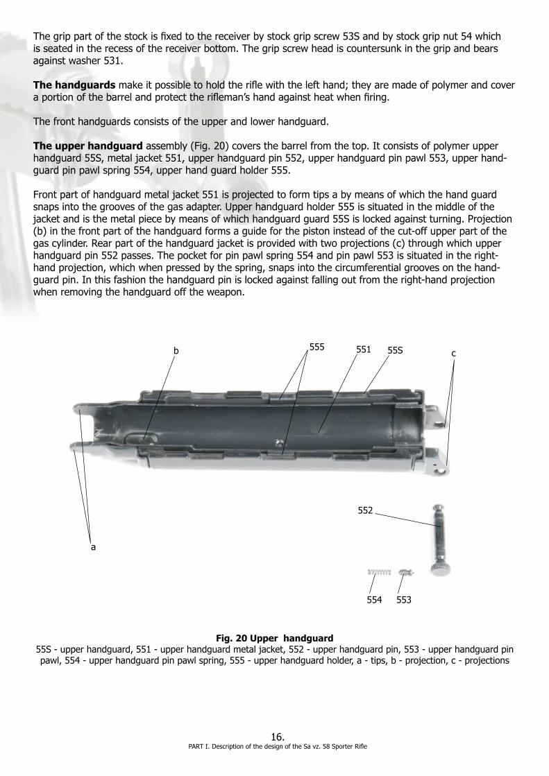
The upper handguardassembly(Fig.20)coversthebarrelfromthetop.Itconsistsofpolymerupperhandguard55S,metaljacket551,upperhandguardpin552,upperhandguardpinpawl553,upperhand-guardpinpawlspring554,upperhandguardholder555.
Frontpartofhandguardmetaljacket551isprojectedtoformtipsabymeansofwhichthehandguardsnapsintothegroovesofthegasadapter.Upperhandguardholder555issituatedinthemiddleofthejacketandisthemetalpiecebymeansofwhichhandguardguard55Sislockedagainstturning.Projection(b)inthefrontpartofthehandguardformsaguideforthepistoninsteadofthecut-offupperpartofthegascylinder.Rearpartofthehandguardjacketisprovidedwithtwoprojections(c)throughwhichupperhandguardpin552passes.Thepocketforpinpawlspring554andpinpawl553issituatedintheright-handprojection,whichwhenpressedbythespring,snapsintothecircumferentialgroovesonthehand-guardpin.Inthisfashionthehandguardpinislockedagainstfallingoutfromtheright-handprojectionwhenremovingthehandguardofftheweapon.
16.PARTI.DescriptionofthedesignoftheSavz.58SporterRifle
Fig. 20 Upper handguard55S-upperhandguard,551-upperhandguardmetaljacket,552-upperhandguardpin,553-upperhandguardpinpawl,554-upperhandguardpinpawlspring,555-upperhandguardholder,a-tips,b-projection,c-projections
55S551
552
553554
555
a
b c

Lower handguard56S(Fig.21)ismadeofpolymerandcoversthebarrelfrombelow.Thefrontendofthelowerhandguardisshiftedinlowerhandguardfronthoop16whichisslippedoverthebarrelandsnappedinbythegasadapterlug.Therearendofthelowerbarrelguardisfixedtothereceiverbypin561.Bothendsofthepinarerivetedover.Thelowerhandguardisprovidedwithgroovesalongbothsidesforafirmergripwhilefiring.
Fig. 21 Lower handguard (56S-lowerhandguard,561-lowerhandguardpin)
CHAPTER 2 - ACCESSORIES and THEIR DESCRIPTION 1. Accessories EachRifleisprovidedwiththefollowingaccessories:
-twomagazines6S-magazinepouch7-sling8-cleaningkitbag9-cleaningrod(two-part)91-oakumcleaningrod92-horsehairbrush93-oilcan94-needle95-cheekpiece96-recoilpad97-promotionalCD98
17.PARTI.DescriptionofthedesignoftheSavz.58SporterRifle
56S561
7
9 91
92
93949597
96
Fig. 22 Accessories6S-magazine,7-magazinepouch,8-sling,9-cleaningkitbag,91-cleaningrod,92-oakumcleaningrod,
93-horsehairbrush,94-oilcan,95-needle,96-cheekpiece,97-recoilpad,98-promotionalCD
6S
8
98
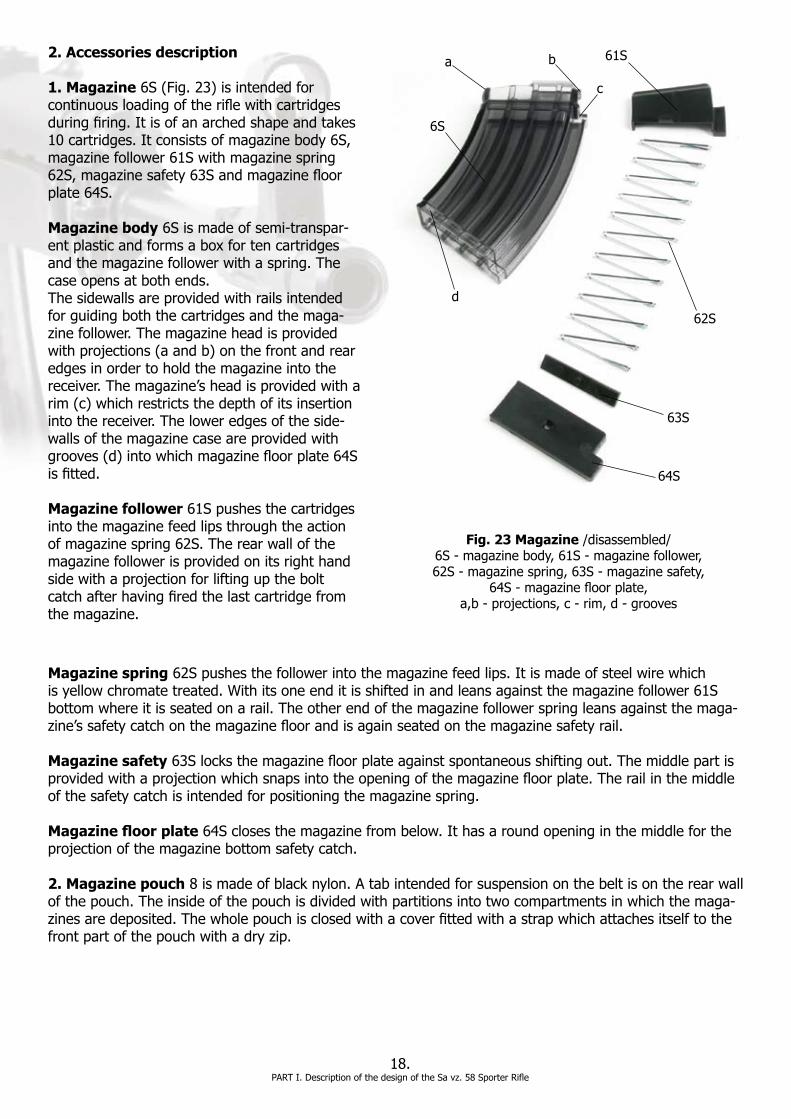
Fig. 23 Magazine/disassembled/6S-magazinebody,61S-magazinefollower, 62S-magazinespring,63S-magazinesafety,
64S-magazinefloorplate, a,b-projections,c-rim,d-grooves
18.PARTI.DescriptionofthedesignoftheSavz.58SporterRifle
6S
61S
62S
63S
64S
a b
c
d
2. Accessories description
1. Magazine6S(Fig.23)isintendedforcontinuousloadingoftheriflewithcartridgesduringfiring.Itisofanarchedshapeandtakes10 cartridges. It consists of magazine body 6S, magazinefollower61Swithmagazinespring62S,magazinesafety63Sandmagazinefloorplate 64S.
Magazine body6Sismadeofsemi-transpar-ent plastic and forms a box for ten cartridges andthemagazinefollowerwithaspring.Thecase opens at both ends. Thesidewallsareprovidedwithrailsintendedfor guiding both the cartridges and the maga-zinefollower.Themagazineheadisprovidedwithprojections(aandb)onthefrontandrearedges in order to hold the magazine into the receiver.Themagazine’sheadisprovidedwitharim(c)whichrestrictsthedepthofitsinsertionintothereceiver.Theloweredgesoftheside-wallsofthemagazinecaseareprovidedwithgrooves(d)intowhichmagazinefloorplate64Sisfitted.
Magazine follower 61S pushes the cartridges into the magazine feed lips through the action ofmagazinespring62S.Therearwallofthemagazinefollowerisprovidedonitsrighthandsidewithaprojectionforliftinguptheboltcatchafterhavingfiredthelastcartridgefromthe magazine.
Magazine spring62Spushesthefollowerintothemagazinefeedlips.Itismadeofsteelwirewhichisyellowchromatetreated.Withitsoneenditisshiftedinandleansagainstthemagazinefollower61Sbottomwhereitisseatedonarail.Theotherendofthemagazinefollowerspringleansagainstthemaga-zine’ssafetycatchonthemagazinefloorandisagainseatedonthemagazinesafetyrail.
Magazine safety63Slocksthemagazinefloorplateagainstspontaneousshiftingout.Themiddlepartisprovidedwithaprojectionwhichsnapsintotheopeningofthemagazinefloorplate.Therailinthemiddleof the safety catch is intended for positioning the magazine spring.
Magazine floor plate64Sclosesthemagazinefrombelow.Ithasaroundopeninginthemiddlefortheprojection of the magazine bottom safety catch.
2. Magazine pouch8ismadeofblacknylon.Atabintendedforsuspensiononthebeltisontherearwallofthepouch.Theinsideofthepouchisdividedwithpartitionsintotwocompartmentsinwhichthemaga-zinesaredeposited.Thewholepouchisclosedwithacoverfittedwithastrapwhichattachesitselftothefrontpartofthepouchwithadryzip.

19.PARTI.DescriptionofthedesignoftheSavz.58SporterRifle
3. Sling8makesitpossibletocarrytherifle;itis1,220mmlongand26mmwide.Asmallbuckleissewedontooneendoftheslingbywhichtheslingmaybeshortenedorextended.Attheotherend,theslingisprovidedwithasewed-onleatherfasteningstrapwithanopeningfortheconnectingbutton.Whenfixingtheslingtotherifle,leatherfasteningstrapmustbefirstpulledthroughtherearswivel,thenthroughthesmallbuckleandthentheleatherstrapshouldbepulledthroughthefrontswivelontheassaultrifleand the connecting button should be buttoned up.
4. Cleaning kit bag9ismadeofstrongtextilematerialandisdesignedtoholdallthecleaningaccesso-riesaswellasneedle95.
Cleaning rod91isintendedforcleaningandlubricatingtheboreandthecartridgechamber.Thecleaningrodconsistsoftwoparts,1and2,whichmustbescrewedtogetherinordertoformonepiecebeforeitisused.Oneendoftheupperpartofcleaningrod1isprovidedwithathreadtowhicheitheroakumcleaningrod92orhorsehairbrush93canbeattached.Thelowerpartofcleaningrod2isprovidedatoneendwithanannulargroovethroughwhichtheneedleispushedaftershiftingthecleaningrodintheopeningoftheplugofoilcan94.Inthisfashionthecleaningrodcanbeturnedalongthegroovesinthebarrel.
Oakum cleaning rod92isdesignedforcleaningtheboreandthecartridgechamber.Oneendoftheoakumcleaningrodisprovidedwithathreadtobescrewedintothecleaningrod(whencleaningthebore)orintotheoil-canplug(whencleaningthecartridgechamberorthegascylinder).Theotherendispro-videdwithacut-outthroughwhichapieceofragcanbeplaced.Themiddlepartoftheoakumcleaningrodisprovidedwithasquarethreadinterruptedwiththreelongitudinalgrooves.Theoakumistobewoundaroundthisthreadwhencleaningtheboreandthecartridgechamber.
NOTE:Oakumcanbefoundataplumbingsupplystoreandisexcellentforcleaningthebore.Itisusedbyseveral armies in Europe.
Horsehair brush93isusedforcleaningandoilingthebore,thecartridgechamberandthegascylinder.Thebrushhasaneckprovidedwithathreadbymeansofwhichitisscrewedintoeitherthecleaningrodortheoil-canplug.
Oil can94isaroundsmallvesselforkeepingthegunoil.Theoilcanneckisprovidedwithaninternalthreadforscrewingontotheoilcanplug.
The oil can plug has three openings. The longitudinal opening is designed for the end of the cleaning rod. Thecrossopeningisdesignedforhousingtheoakumcleaningrodorthehorsehairbrushwhilecleaningthecartridgechamber.Thelast(cross)openingisforfixingneedle95.Theunscrewedplugwiththekeythen serves as the cleaning rod handle.
Needle95isusedwhendisassemblingandcleaningtherifle.Someneedleshavespannerlikeopeningsintended for adjustment for the height of the front sight.
5. Cheek piece96iscoveredwithcheekpiecepad961andisdesignedtoallowmorecomfortableshoot-ing.
6. Recoil pad97ismadeofrubberandprovidessignificantreductionofrecoilfeltbyshooter.
7. Promotional CD98includesamongtheotherallimportantinformationonSavz.58Sporterrifle.
CHAPTER 4 - AMMUNITION
1. Types of cartridges Only7.62x39mmcartridgesmaybeusedintheSavz.58Sporterrifle.Theyshouldonlybeofexcellentqualityandmanufacturedbyacompanyknownfortheirqualitycontrol.
Cartridgeswithrustyspotsonthemmustbewipedwithadrycloth.Cartridgeswhichhavebeenunpackedforalongertimemustbewipedwithadryclothbeforeloadingthemagazine,andcheckedforlengthandturningofthebullets.Whensomecartridgesareinuseandfrequentlyrammedintomagazinesforalongertime, loosening of the bullet in the cartridge case neck, possible pushing in of the bullet into the cartridge caseorturningofthebulletmayoccur.Inthesecases,thewater-tightnessandoil-tightnessofthecar-tridgesaredecreased.Cartridgeswithpushed-inorturningbulletsmustnotbeused,butdisposedaccord-ingtovalidregulations.Neverusedefectivecartridgesforfiring(thoseconsiderablyrusted,withdamagedcartridgecasesorbullets,withadamporoiledpowderchargeorwithbulletspushedinthecartridgecasesandthelike).
Neverstrikethecartridge,primerorbulletwithahammerorotherhardobjects.
2. Loading the magazine
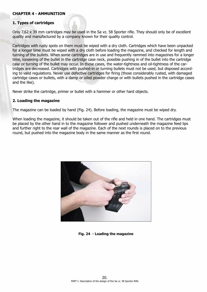
Themagazinecanbeloadedbyhand(Fig.24).Beforeloading,themagazinemustbewipeddry.
Whenloadingthemagazine,itshouldbetakenoutoftherifleandheldinonehand.Thecartridgesmustbeplacedbytheotherhandintothemagazinefollowerandpushedunderneaththemagazinefeedlipsandfurtherrighttotherearwallofthemagazine.Eachofthenextroundsisplacedontothepreviousround,butpushedintothemagazinebodyinthesamemannerasthefirstround.
20.PARTI.DescriptionofthedesignoftheSavz.58SporterRifle
Fig. 24 - Loading the magazine

PARTII.FunctioningoftheRifleandTroubleshooting,Storage,Inspections,Maintenanceand Repairs
CHAPTER 1 - FUNCTIONING OF THE PARTS AND MECHANISMS OF THE RIFLE 1. Preparing the rifle for shooting
Beforefiringariflewhichhashadalayerofvaselineappliedforalongorshort-termperiod, itmustbecleanedandthepreservingagentremoved.Theriflemustbethendisassembledandallpartsallwipeddry.Afterwards,theassembledrifleshouldbepreservedwithaqualitygunoil.
Directlypriortofiring,wipedrytheboreandthecartridgechamber.
Whendisassembling,cleaningandassemblingtherifle,allthecomponentsshouldbeinspectedandcheckedtoseewhethertheyareworntoanexcessivedegree,battered,brokenordamagedinsomeotherway.Whenassembling,thefunctioningoftheparticularmechanismsshouldbechecked.Specialattentionshould be paid to checking the functioning of the assembled trigger mechanism, the reliable functioning of the safety catch, to the disconnector, to the sear and the condition of the magazine.
Aftercompletelyassemblingtherifle,thefunctioningoftheboltshouldbecheckedbyhandcocking.Properfeedingischeckedbychargingtheriflewithafewpracticeroundsfromthemagazine(byhandcocking).
Therifleismadereadyforfiringbyinsertingtheloadedmagazineintothemagazinewellofthereceiverandcockingthegunbymovingtheboltintotheextremerearpositionfromwhichitisreleasedwithoutholdingthebolthandleanylongerorbymovingtheboltforwardbyhand.Duringthisoperationthefingermustbeoffthetrigger.Thesafetycatchshouldbeturnedintoitsforward(fire)positiononlypriortofiring.
21.FunctioningoftheRifleandTroubleshooting,Storage,Inspections,MaintenanceandRepairs
Fig. 25 Position of the parts in loaded rifle
22.FunctioningoftheRifleandTroubleshooting,Storage,Inspections,MaintenanceandRepairs
2. Functioning of the rifle parts
Firing
Onemayopenfireatanobjectaftersettingtherearsighttoanappropriaterangeoffireandafteradjust-ingthesafetycatchwingintothe“fire”position,i.e.forward.
Whenturningthesafetycatchwingintothepositionforfiring,thesafetycatchengagesthedisconnector,byputtingitintothesafetycatchgroove,withthesear.Thedisconnector,whichisbeingconstantlypushedupbyitsownspring,hooksthesearandcontrolsitsloweringandlifting.
Bysqueezingthetriggertowhichthedisconnectorispivoted,thesearisloweredandthestriker,whichisunderthepressureofitsspring,isreleased.Thestrikerthushitsagainstthefiringpinwhichinitiatesthecartridgeprimerinthecartridgechamber.Thecombustionofthepowderthatfollowscreatesgases,thepressureofwhichsendsthebulletintothebarrel.Assoonasthebulletpassesthegaschannelofthebarrel,aportionofthepowdergases,penetratesintothegascylinder,whereithitsthepistonhead,thussettingitinabackwardsmotion.Thepistonstrikesthefaceoftheboltcarrierthussendingittoitsrearposition. The piston is, nevertheless, retained by bearing its conical surface against the face of the recess and returned by the piston spring to the original position. At this time, the bullet has already left the barrel andthepressureinthebarrelhasdecreased.Withitsunlockingtip,theboltcarrierthenpullsthelockingpiece from the locked position. The locking piece folds into the recess in the bolt carrier over the unlock-ingtip.Fromthismomenton,allthecomponentsoftheboltmovetogetherbackwards.Thebeginningofthemotionoftheboltcoincideswithbeginningtheextractingofthefiredcartridgecasefromthecartridgechamber.Thefiredcartridgecaseispulledbytherimofthebasebytheextractorclawuntilthemomentwhenthebottomrimofthecartridgecasebasestrikestheejectorandthecartridgecaseisthrownoutoftherifle’sreceiverupwardstotheright.
Meantime,boltcarriersideplaterunsontothedisconnector’sluganddepressesthedisconnector,thusdis-engaging it from the sear so that the sear is lifted up through the action of the arm of the trigger mecha-nism feather even if the trigger is squeezed.
Assoonastheboltmovingbackwardshasruntoitsextremerearposition,theboltcarrierstrikesagainstthereturnmechanismbase,stopsitsmotionandthewholeboltassemblythenreturnstoitsfrontposition,beingactuatedbythereturnspring.Thestrikerbeingdrivenbythestrikerspringcatchesthesearwithitsnose. The ramming lug of the bolt pushes the top round out from the magazine feed lips and rams it into thecartridgechamber.Thebaseofthecartridgecasebearsagainsttheboltheadpocket,atwhichtheextractorclawsnapsintothegrooveofthebaseofthecartridgecase.Duringtheboltcarrier’sforwardmo-tion, the locking piece falls into the receiver lugs and locks its position.
Inordertofirethenextshot,itisnecessarytoreleasethetriggerandsqueezeitagain.
Theriflemaybelockedagainstanunintendedshotbyadjustingthewingofthesafetycatchintotheverti-calposition.Wheninthisposition,thesafetycatchdisengagesthedisconnectorfromthesear,preventingitfromloweringandthusreleasingthestriker.Inthisfashiontherifleisnotcapableoffiringiftherifle’ssafety is in the locked position.
Thismodeoflockingdoesnotinanywayrestrictthenormalfunctioningoftheotherpartsoftheboltwiththeexceptionofthestriker.Itisconsequentlypossibletoloadaswellasunloadthecartridgefromthechamberwhentheweaponislocked.

23.FunctioningoftheRifleandTroubleshooting,Storage,Inspections,MaintenanceandRepairs
Ceasingfire
Ceasingfiremaybetemporaryorpermanent.
Firingistemporarilyceasedautomaticallyaftereveryshot,regardlessofwhetherthetriggerisreleasedorsqueezed;thenextsingleshotmaybefiredonlybysqueezingthetriggeragain.
Afterfiringthelastcartridgefromthemagazine,theboltremainsintherearposition;afterre-placingtheemptymagazinewiththefulloneandpullingtheboltcarrierbackwardsbyitscockinglever,theboltcatchisreleased(forthefollowerpushingthecatchupisdowninthemagazineagain)andfiringmayberesumed.
Incaseoftemporaryinterruptionoffire,theriflewillbelockedagainstanunintendedshotbyturningthewingofthesafetycatchdownwards,asthecartridgechamberhasacartridgeinsideitand the striker is in the rear cocked position. Firing may be reopened immediately after adjusting thesafetycatchwinginto“Fire”position. Terminationoffiringandunloadingtherifle
Afterterminatingfire,theriflemustbelocked.Whenunloadingtherifle,takeoutthemagazine(Fig.27)andthroughcockingthebolt,ejectthecartridgefromthecartridgechamber.Thenad-justthesafetycatchwingintheposition“Fire”,pulltheboltbyitscockingleverbackwardsandwiththetriggerbeingsqueezed(releasingthestriker),lettheboltgotothefrontposition(toreleasethestrikerspring).Thenre-locktheassaultrifle.Taketheremainingcartridgesoutofthemagazineandslidetheemptymagazineintotherifle.
CHAPTER 2 - TROUBLESHOOTING
1. General rules for preventing malfunctioning
Therifleisareliabletrouble-freefirearmifcorrectlyhandled,carefullyoperatedandmaintained.Nevertheless,iftherifleisexposedtolong-lastingactivity,troublesinfiringmayoccurduetowearorbreakstosomeofthecomponents,duetodirtintheriflemechanisms,defectivecartridg-es,carelesshandlingorinsufficientmaintenanceoftherifle.Theabove-mentionedcircumstancesaffectthenormalfunctioningoftherifleandcanresultinmalfunctionsandtroubleswhenfiring.
Mostmalfunctionsandtroubleswhichoccurwhenfiringtheriflemaybeeasilysolvedbysimplerepeat-ing–pullingtheboltcarrierbythecockinglevertoitsrearposition;ifamalfunctionisnoteliminatedbyrepeatingor,ifeliminated,itre-occurs,itisnecessarytounloadtherifleandfindthereasonbehindthemalfunction.

In order to prevent malfunctions in firing, it is necessary:
-tostrictlyfollowtheinstructionsregardingmaintenance,disassembling,assembling,cleaning, inspectingandpreparingtherifleandcartridgesforfiring;-toprotectthecomponentsandmechanismsoftheriflefromdirt;-nottouseforcewhenremovingmalfunctionswhichmightcausedamagetothecomponents;-tocarefullyinspectthecartridgesandmagazinesbeforeloadingthemagazines.Donotload magazineswithdefectiveorrustycartridges,wipethecartridgesandremovepossibleimpurities withadryclothbeforeloadingthemagazines;-tooilthecomponentsthatworkagainsteachotherduringtheirfunctioningbeforefiring;clean anddrytheboreandthecartridgechamber;-tocheckfromtimetotimetheconditionoftheriflecomponentsandmechanismsatbreaksin firing,removethickenedlubricantandimpuritiesoffthefrictionsurfaces;re-oilthefriction surfacesaftercleaningthem;-tocarefullyprotecttheriflefrompenetrationofimpurities(dust,sand,earth)intothemuzzle whenfiring,whenonthemoveandwhentakingfiringpositions;protecttheriflefromimpact
2. Typical malfunctions, their causes and solutions
Kindsofmalfunctionsandtroubles,theircausesandwaysofmethodsofremedyareindicatedinthebelowtable:
24.FunctioningoftheRifleandTroubleshooting,Storage,Inspections,MaintenanceandRepairs
Malfunction Cause Remedy
1. Misfiring No shot after squeezing the trigger
1.Damagedfiringpin,ifthere is no dimple on cartridge primerleftbyfiringpin impact
2. Fatigued or broken striker spring,ifpoortraceoffiring pin on cartridge primer
3. Defective cartridge
1.Replacefiringpin
2. Replace striker spring
3. After a lapse of about 10 seconds(dangerofdelayed ignitionofpowdercharge), by hand recharging, eject the cartridge from the chamber. Inspect the ejected cartridge and if the primershowsadequate dimple caused by strike of firingpin,replacethe cartridge
2. Piston is not returned to front position
Fatigued or broken pistonspring
Replace piston spring

25.FunctioningoftheRifleandTroubleshooting,Storage,Inspections,MaintenanceandRepairs
3. Half-closed bolt Bolt carrier does not bear against the face of the receiver
1. Dirty bolt
2.Defective(deformed) cartridge
3. Dirty cartridge chamber
1. Disassemble the bolt, clean it and oil it
2. By hand recharging eject the cartridge from the cartridge chamber
3. Clean the cartridge chamber
4. Cartridge not fed 1. Dirty interior of magazine
2. Brokenmagazinewallsor broken magazine feed lips
3. Fatigued or broken spring ofmagazinefollower
4.Shortrecoilofbolt- dirtyrifle
1. Disassemble and clean the magazine
2. Replace the magazine 3.Replacemagazinefollower spring
4. Disassemble and clean therifle
5. Cartridge case does not extract
1. Broken extractor spring
2.Broken-offextractorclaw
1. Replace extractor spring
2. Replace the extractor
6. Cartridge case does not eject
1. Short motion of bolt backwards-dirtyrifle
2. Broken piston
1. Disassemble and clean therifle
2. Replace the piston
7. Cartridge jumps out of the magazine
Magazinefollowerspringistoo strong or feed lips are broken
Replace the magazine
8. Bolt is not retained by bolt catch after firing last round
1. Defective magazine or its spring
1. Replace the magazine or its spring
If the above-mentioned malfunctions cannot be fixed or if any other malfunctions reoccur, the rifle should be sent for repairs to an authorized gunsmith appointed and approved by the manufacturer.

CHAPTER 3 - STORAGE
1. Storing the rifle
Therifleshouldbedepositedinaverticalpositionwiththemuzzleuporinahorizontalpositioneitheronariflerackoronashelf.Itcanalsobesuspendedbythesling.Theboltshouldbeinthefrontposition,thestrikerreleasedandthesafetycatchwinginthevertical(locked)position.Themagazinesshouldbeputinthe magazine pouch and other accessories in cleaning kit bag.
Whentransported,therifleshouldbeplacedinaspecialtransportboxorbaginordertopreventitfromdamage.Ifinadequatepackagingisusedwhentransportingtherifle,itisofutmostimportancetoprotectthesightdevicesagainstdamagebywrappingthefrontsightandrearsightinragsandfillingtheemptyspaceintheboxwithragsinordertopreventtheriflefrombeingbatteredabout.
In any of the mentioned modes of deposition, the rifle must not be loaded!
Thedepositedriflemustbeconstantlykeptsafeandthekeysfromthelocksoftheracks,shelves,cabinetsorsafesholdingtheriflemustbekeptinasecureplace.
Do not plug the borewithpaper,ragsorotherobjectsregardlessofthestorageconditions,orbarrelbulge or additional damage may occur.
Afterterminatingshooting,riflemustbecleanedeachtime.Specialattentionshouldbepaidtocleaningoftheboreandcartridgechamber.Allaccessoriestotheriflemustbekeptingoodcondition,cleanandap-propriately deposited.
CHAPTER 4 - INSPECTION OF THE RIFLE
1. Principles of inspection of the rifle
Regularinspectionsoftheassembledanddisassembledrifleshouldbecarriedoutregularly.Theextentofdisassemblingshouldbedeterminedbytheinspectingperson.Theowneroftherifleshouldinspectitbefore leaving for the shooting range and during cleaning.
Alongwiththeinspectionoftherifleallspecifiedrifleaccessoriesshouldbeinspected. Whennotusedtheassembledrifleshouldbeinspectedonceamonth.Oninspectionoftherifle,itisnecessarytocheck:
-whetherthereisanyrustytintonthemetalpartsofrifle,whetherthemetalpartsaresoiled, batteredorscratchedandwhethertheplasticpartsoftheriflehavesplitorcracked.-whetherthefrontsightorrearsightaredamaged,whetherthesightinggaugemarksare oppositeeachother,whetherthefunctioningoftheslideandtherearsightplungeriscorrect;-whetherthemagazinesareundamaged
26.FunctioningoftheRifleandTroubleshooting,Storage,Inspections,MaintenanceandRepairs

Inspection of the assembled rifle
Wheninspectingtheassembledrifle,itisnecessarytocheck:
a)The functioning of the bolt:Oncockingthebolt,themotionofthecomponentsmustbetrouble-free,withoutseizingup,withconsiderableresistanceonthepartofthereturnspring.Onreleasingthebolt,thismustmoveenergeticallyforwardsatwhichtheboltcarriermustrunasfarasitsextremefrontposition and lean against the face of the receiver. Ifanemptymagazineisshiftedintotherifle,theboltcatchmustretaintheboltintheopenpositionwhentheboltmovesforward.Correctnessoffeeding,extractingandejectingmaybeverifiedbyhandchargingatwhichthemagazine,insertedintherifle,isloadedwithpracticerounds.Inthisway,thefunctioningofthemagazine,oftheextractorandoftheejectormaybeverified.Atthesametime,thefunctioningofthemagazinecatchisverified.Wheninsertingthemagazineintotherifle,themagazinecatchmustaudiblysnapinbehindtheprojectionattherearedgenearthemagazinefeed lips. If not depressing the magazine catch, the magazine must not be released from the receiver.After checking the functioning of the bolt, the striker spring should not remain depressed.
b)The functioning of the trigger mechanism: The functioning of the trigger mechanism should only be checked when using practice cartridges. Insertapracticeroundintothecartridgechamberbyhandcharging;thesafetycatchwingisadjustedtothe“Fire”position.Inthepositionofthesafetycatchwing,thestrikermustbereleasedbysqueezingthetriggerandaudiblystrikingthefiringpin.Ifthesafetycatchwingisadjustedinthe“Safe”position,i.e.,downwards,thestrikermustnotbereleaseduponsqueezingthetrigger.Whenadjustinganyofthetwopositions,thesafetycatchmustbeturnedtosuchadegreethatanaudibleclickisheard;tochangethepositionofthewing,acertainforcemustbeexerted. c)The correctness of the rear sight and the front sight:Itisnecessarytocheckwhethertherearsight leaf is lacking side clearance and is not bent. If the plunger is depressed, the slide must easily move alongtheleafandmustbeforceddownbytherearsightfeathertotherearsightrampinallpositions.Theplunger lug must be able to snap into all the notches on the leaf. Regardingthefrontsight,itisnecessarytoverifywhetheritisdamaged,whetherthesightinggaugemarksareoppositeeachother,andwhethertheadjustmentfortheheightofthefrontsightisnotimpaired(thismaybedeterminedfromtheintegrityofthedropofredlacquerinsidethefrontsightcover).
d)The functioning of the stock: It should be checked in order to assure that the stock is tightly se-curedtothereceiver,issteadyanddoesnotwobblesignificantly.Thestockshouldalsobecheckedforanycracks.
Inspection of the disassembled rifle
Beforeadisassembledrifleisinspected,allthecomponentsmustbewipeddry.Whentherifleisdisassem-bledallthecomponentsmustbecarefullyinspectedinordertodeterminewhethertheyarefreeofrust,whethertheyaresoiled,crumbledoff,battered,seizedorexcessivelyworn.Additionally,thecomplete-ness of the rifleshouldbeverified.
27.FunctioningoftheRifleandTroubleshooting,Storage,Inspections,MaintenanceandRepairs

Defectivecomponentswhichrevealfissures,rubbed-outspots,excessivelywornactivesurfaces,strippedthreads,loosenedconnectionsorthosethataredeformedand/orbrokenmustbereplaced.
Wheninspectingthebore,itisnecessarytoliftthebarreltogetherwiththereceiveruptotheheightoftheeyesandturntheotherendofthebarreltowardthedirectionofthebestlight.Whileslowlyrotatingthebarrel, it is necessary to carefully inspect the grooves of the bore, starting from the muzzle to the direction ofthereceiver.Inorderthatthewallsoftheboremaybebetterseenalongallthelengthofthebarrel,itisnecessarytovarythedistanceofone’seyefromthemuzzle.
Wheninspectingthebore,thefollowingdefectsortroublesmaybediscovered:
-theremainsofburntpowderorrustthatappearsasadarktint.Rustorremaindersof burntpowderundistinguishablebytheeyemaybefoundoutbymeansofawhiteclothwhich willshowdarkbrownorblackspotsafterwipingthebore.Greyspotsintheborethatdonot leavespotsontheclothafterwipingtheborearenotafault; -rustthatappearslikedotsorsmalldropsonsomespotsoralloverthebore shallowdarkspotsthatremainafterderusting
-pitscausedbyrustarepitsinthemetal,visibletotheeye
-acoppercoatingwhichiscausedbyfiringwithprojectilesprovidedwithtombackjacket;they appear to the eye as a slight copper coat or bulge in the bore
-scratchesintheshapeofdashes,manytimeswithdistinctprolapsesofmetalonthebore surface
-rounding(wear,spallingofthechromelayer)offieldsmanifestingitselfparticularlyontheleft- handedgesofthefields;itoccursmostoftenbehindthecartridgechamberandnearthemuzzle
-darkspotsandanirregularsurfacebehindthecartridgechamber(spalledchrome),whichisa symptom of burning up the transition cone
-abulgeintheshapeofatransversaldarkring;ariflewithabarreldamagedinthiswaymust notbeusedforfiringunlesstherifleischecked.
-bendingofthebarrelthatmanifestsitselfasanirregularlengthofshadeintheborewhen rotatingthebarrel;batteredspotsontherearfacewallofthebarrel,andscratchesinthe cartridge chamber.
28.FunctioningoftheRifleandTroubleshooting,Storage,Inspections,MaintenanceandRepairs
Wheninspectingthepiston and the gas adapter check:
-whetherthepistonheadisexcessivelyburntorbattered; -whetherthegascylinderisseizedorburntthroughandwhetherthereisnodeposit ofcarbonandimpuritiesontheinternalwalls; -whetherthepistonmovestrouble-freewithoutseizinginthegascylinder.
Wheninspectingthereceiver check:
-whethertheguidebars,groovesandtheactivesurfacesarescratchedorrubbedby pressing;aglossyappearancetothesurfacesoftheprojectionsonwhichthelocking piecelocksispermissible; -whethertheejectorisforcedin,brokenoffordisplacedinthegrooves; -whethertheboltcatchiscracked,brokenofforforcedin; -whetherthesafetycatchholderisbroken; -whetherthelacqueronthereceiverisscratchedoff; -whetherthepistonmovesfreelyalongtheguideintherearsightbase.
Wheninspectingthebolt check:
a)Bolt carrier:
-whethertheguidebars,groovesandactivesurfacesarescratchedorrubbedby pressing;inspectifthefacebearingsurfaceisrammeddown; -whetherchromelayeronthesurfacesandedgesisspalledorcrumbledoff
b)Bolt:
-whetherthecartridgecasebedandtheopeningforthefiringpinareburntoff; -whethertherearefissures,pitsormetallicdepositsaroundtheopeningfor thefiringpin; -whethertheactivesurfacesarerubbedbypressingorrammeddown; -whethertheendoftheopeningforthefiringpinisflattened,i.e.,whether thefiringpinpassesfreelythroughtheopeninginthecartridgecasebed;Pin mustshiftoutofbolt’sopeningwhentheboltisoverturnedbyitsown weightor,atthemost,whentappingslightlywiththeboltagainstthepalm; -whethertheextractorclawispressedwithsufficientforceintheboltcartridge casebed; -whethertheextractorisclampedbythewallsofitsgroove,i.e.,whetheritreturns, afterbeingdeflected,energeticallytotheinitialposition; -whethertheextractorhasfissuresorwhethertheextractorclawisbrokenoffor damagedinsomeotherway.
c)Locking piece
-whetheritmovesfreelyinthebearingsofthebolt; -whethertheedgesoflockinglugsarebatteredordeformedinsomeotherway; a glossy appearance of the active surfaces of the locking lugs and of the upper (glide-over)surfaceispermissible; -whetherthelockingpiecetiltsoverbyitsownweightintothelockedposition; -whetherthechromelayeronthesurfacesoredgesisspalledorcrumbledoff.
29.FunctioningoftheRifleandTroubleshooting,Storage,Inspections,MaintenanceandRepairs

30.FunctioningoftheRifleandTroubleshooting,Storage,Inspections,MaintenanceandRepairs
d)Striker:
-whetherthenoseofthestrikerheadiswornouttoexcess; -whetherthestrikerpassesfreelythroughtheopeningintheboltcarrier.
Wheninspectingthetrigger mechanism check: -whetherthetrigger,disconnectorandsearpivotarefreeontheirpins; -whetherthearmofthetriggermechanismfeatherisbrokenorbentandwhetheritis inthecorrectpositionunderthesear; -whethertheseariswornouttosuchanextentthatitdoesnotcatchthestriker reliably.
Wheninspectingthestock and front handguards check: -whethertheplasticpartsarecracked,batteredordeformedinsomeotherway; -whetherthestockisloosened; -whethertheswivelonthestockisloosenedordamaged;
2. Disassembling the rifle
Therifleisdisassembledforthepurposeofcleaning,preserving,forinspectionandwhenreplacingand/orrepairing its parts.
Therearetwowaysofdisassemblingtherifle:
-partialdisassemblingand -completedisassembling.
Partialdisassemblingoftherifleiscarriedoutbytheownerforthepurposeofcommoncleaning,preserv-ing and inspecting.
Completedisassemblingoftherifleisonlycarriedoutwhenreplacingandrepairingitspartsatanautho-rizedgunsmithworkshop.
Disassemblingandassemblingtoofrequentlyharmstherifleasthewearonitscomponentsisaccelerated.
Whendisassemblingandassemblingtherifle,thefollowingrulesmustbeobserved:
-Disassemblingandassemblingoftherifleshouldbecarriedoutonatableorbench;wheninthe field,thisshouldbecarriedoutonacleananddrysheet.
-Everytime,beforedisassemblingtherifle,themagazineshouldbetakenoutandmadesure there is no cartridge in the cartridge chamber.
-Whenseparatingandassemblingthecomponents,handlethemwithcare,donotuseforceasit could cause damage.
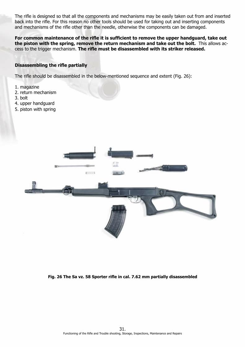
Therifleisdesignedsothatallthecomponentsandmechanismsmaybeeasilytakenoutfromandinsertedbackintotherifle.Forthisreasonnoothertoolsshouldbeusedfortakingoutandinsertingcomponentsandmechanismsoftherifleotherthantheneedle,otherwisethecomponentscanbedamaged.
For common maintenance of the rifle it is sufficient to remove the upper handguard, take out the piston with the spring, remove the return mechanism and take out the bolt.Thisallowsac-cess to the trigger mechanism. The rifle must be disassembled with its striker released.
Disassembling the rifle partially
Therifleshouldbedisassembledinthebelow-mentionedsequenceandextent(Fig.26):
1. magazine2. return mechanism3. bolt4. upper handguard5.pistonwithspring
31.FunctioningoftheRifleandTroubleshooting,Storage,Inspections,MaintenanceandRepairs
Fig. 26 The Sa vz. 58 Sporter rifle in cal. 7.62 mm partially disassembled

a)Taking out the magazine(Fig.27):Holdtheriflebythegripwiththerighthandandgraspthefrontwallofthemagazinewiththelefthand.Leantheleft-handthumbagainstthemagazinecatchandpushitforward.Simultaneously,tiltthemagazineforwardinthedirectionofthebarrelandpullitoutfromthereceiver’smagazinewell.
b)Removing the return mechanism(Fig.28-29):Withthelefthandgrasptheriflefrombelowbythereceiverandbythethumboftherighthand,thepalmofwhichleansagainstthetopofthebuttstock,depresstheprotrudingendofreceivercoverpin.Thengrasptheknurledheadofthepinbytheright-handthumbandindexfingerandpullthepinouttotherightuntilanaudibleclickisheard.
Graspthetopofthebuttstockwiththerighthandandleantheright-handthumbagainsttherearwallofthereceivercover.Throughforwardpressureofthethumbandanupwardshift,movethebaseofthere-turnmechanismoutfromthereceiverrecess,andbypullingbackwards,pullallthereturnmechanismoutoftherifle(Fig.28).Oryoucanusetherighthandforholdingtheriflebythegripandplacethepalmofthelefthandonthetopofreceivercoverwiththumbbehindtherearendofthecover.Bypushingforwardandliftingup,thecovercanberemovedfromthereceiverandpulledout(Fig.29).
32.FunctioningoftheRifleandTroubleshooting,Storage,Inspections,MaintenanceandRepairs
Fig. 27 Taking out the magazine
Fig. 28 Removing the return mechanism Fig. 29 Removing the return mechanism

c)Taking out the bolt(Fig.30):Holdtheriflewithrighthandbythegriporfrombelowthereceiverandpointthemuzzletothegroundand.Withthelefthandusingthecockinglever,pulltheboltcarrierbackwardstoastop.Withtheuseofmiddlefingerandthethumb,taketheboltcarrieroutofthereceiver.Allthetimethewholeboltassemblyisbeingtakenout,itsfronthastobepointingdown,inordertopre-vent the striker from moving out of the bolt carrier shaft and bolt falling out.
Thentaketheboltcarrierbythelefthandandwiththerighthandgraspthestrikerbyitsheadandpullitoutoftheboltcarrier.Whiledoingthis,turnthestrikerslightlytotheleftuntiltheprojectionoftheboltcarrier passes through the cross groove to the neighboring through groove. Continue pulling the head of the striker, shift the striker completely out of the bolt carrier. The bolt is thereby released. Remove the lock-ingpiecefromtheboltbytiltingitupwards.
Fig. 30 Taking out the bolt
33.FunctioningoftheRifleandTroubleshooting,Storage,Inspections,MaintenanceandRepairs
d)Removing the upper handguard:Depresstheprojectingpartofbarrelguardpin552withtherighthandthumb.Withtherighthandthumbandindexfingergraspthebarrelguardpinbyitsknurledhead and pull it entirely to the right. After shifting the barrel guard pin out, lift the rear part of the barrel guardupabit,withtherighthand,andtiltitupwardsinthedirectionofthemuzzle.Inthisway,thetipsofthe barrel guard are shifted out from the grooves of the gas adapter and the barrel guard may be removed fromtheweaponbypullingitbackwards.
e)Removing the piston(Fig.31):Holdtheriflefrombelowwithonehandandgraspthepistonwiththeotherhandandpushitbackwardstoastopagainsttheactionofthepistonspring.Thentiltthepistonupwardsfromthegascylinder.Inthisway,thepistonheadcomesabovetheupperwallofthegascylin-der;bypullingthepistonaskanceforward,takethepistonoutfromtherecessintherearsightbase.Ifthepistonspringhasnotbeenshiftedouttogetherwiththepiston,shiftitoutbyusingtherearendofthepiston.

34.FunctioningoftheRifleandTroubleshooting,Storage,Inspections,MaintenanceandRepairs
Fig. 31 Removing the piston
3. Assembling the partially disassembled rifle Thepartiallydisassembledrifleshouldbeassembledinthefollowingorder:
a)Insert the piston with the spring:Shiftthepiston,withthespringoveritscylindricalpart,intherecessoftherearsightbaseaskancedownwardstoastop.Tiltthepistonheadtotheroundofthegascylinder and release the piston. Through the action of the spring the piston comes to its front position.
b)Put the upper handguard on: Make the tips of the upper handguard front hoop snap into the grooves on the gas adapter and tilt the upper handguard. Shift the upper handguard pin completely to the left. The upper handguard is thus locked against falling out.
c)Assemble the bolt:Mountthelockingpiecewithitsjointsintothebearingsofthebolt.Inserttheboltintherecessintheboltcarriernearthebridge.Shiftitforwardinordertoengagethegroovesinthecarrier. Shift the striker in the bolt carrier so that the gauge mark on the striker is opposite the gauge mark ontherearwalloftheboltcarrier.Thenturnthestrikerbythewholelengthofthegaugemarktotherightand shift it to a stop in the bolt carrier.
d)Put the bolt carrier into the receiver:grasptheassembledboltcarrierwithonehandsothatthethumbleansagainstitsrearfaceandthemiddlefingeragainstitsfrontface.Holdtheriflefrombelowwiththeotherhandbythereceiverwiththemuzzlepointingslightlydownwards.Inserttheboltcarrierfromaboveintherearpartofthereceiver.Shifttheinsertedboltcarrierasfarforwardaspossible.Thestrikerwillremainretainedbythesear.Setthesafetycatchto“Fire”positionandsqueezethetrigger;thestrikeris then released by the sear.
e)Insert the return mechanism: First of all, partially shift the return spring in the cavity of the bolt carrierandthenthestikerspringintheopeningofthestriker.Pushthefrontpartofthecoverdowninor-dertoengagethegroovesintheboltcarrierandbypushingforwardsanddownwardsshifttheprojectionof the base in the recess in the rear part of the receiver. Lock the return mechanism by shifting the pin of the receiver cover to the left until an audible click is heard.
35.FunctioningoftheRifleandTroubleshooting,Storage,Inspections,MaintenanceandRepairs
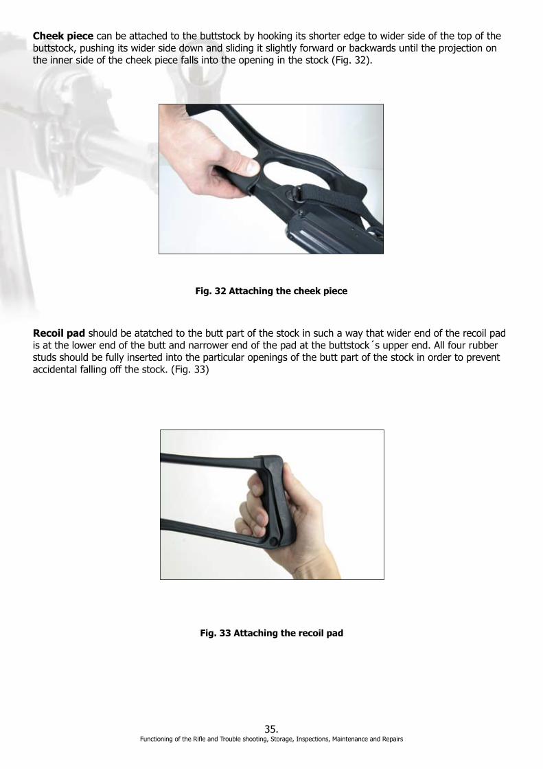
Cheek piececanbeattachedtothebuttstockbyhookingitsshorteredgetowidersideofthetopofthebuttstock,pushingitswidersidedownandslidingitslightlyforwardorbackwardsuntiltheprojectionontheinnersideofthecheekpiecefallsintotheopeninginthestock(Fig.32).
Recoil padshouldbeatatchedtothebuttpartofthestockinsuchawaythatwiderendoftherecoilpadisatthelowerendofthebuttandnarrowerendofthepadatthebuttstock´supperend.Allfourrubberstuds should be fully inserted into the particular openings of the butt part of the stock in order to prevent accidentalfallingoffthestock.(Fig.33)
Fig. 32 Attaching the cheek piece
Fig. 33 Attaching the recoil pad

CHAPTER 5 - MAINTENANCE
1. The main principles of rifle maintenance
Oneoftheconditionsforreliablefunctioning,accuracyoffireandtheservicelifeoftherifleiscorrectandtimelycleaningandpreservingaswellasinspections.Theriflemustalwaysbekeptingoodorderandclean.
MaintenanceandcareoftheSavz.58Sporterrifleisdividedinto- dailycare,- andmonthlycare.
Daily careoftherifleshouldbecarriedoutassoonaspossibleaftershooting.Theextentofthecareisdeterminedaccordingtotheneedswhichdependeontheconditionsoftheshooting,fromtheweatherconditionsandthelike.Afterreturningfromshooting,therifleshouldbepartlydisassembledandallthemainpartscompletelycleaned.Overthefollowing3to4days,checktherifleforrust.If,indoingthis,itstillshowstracesofimpuritiesduetocombustionproductsorrust,thecleaningprocedureshouldbere-peated. Onlyafterpropercleaningandwipingtherifledry,itcanbepreservedwithoil.
Monthlycareshouldbecarriedouteveniftherifleisnotfiredwithinthistime.Atmonthlychecks,therifleshouldbecheckedforanypossibleruststainsandsufficientoilpreservation.
Iftheabove-mentionedprinciplesareobserved,anyinadequatedeteriorationofthetechnicalconditionoftheriflecannotoccur.
2. Cleaning and preserving agents
Whencleaningandpreservingtherifle,onlyspecifiedcleaningandpreservingagentsofhighqualityshouldbe used.
To cleantherifleonlythefollowingmaterialshouldbeused: -cleansoftrags(coloredaswellaswhite)tocleanandpreservethecomponents -brassborebrush -cottonpatches -highqualitygunoil -horsehairbrush(partoftherifleaccessories). -toothbrush
To preserveriflesthefollowingshouldbeused: -RIGtoprotectthemetalpartsoftherifleagainstcorrosion.Thisproductmaybeused all year. -gunoiltolubricatethefrictionsurfacesintheriflethatareinuse
The cleaning agents must be protected from dust and moisture contamination.
36.FunctioningoftheRifleandTroubleshooting,Storage,Inspections,MaintenanceandRepairs

3. Procedure in cleaning and preserving the rifle
Afterfinishingshooting,therifleshouldbepartiallydisassembledforcleaning.Completedisassemblingoftherifleforcleaningisonlynecessarywhentherifleisstronglysoiledorwhenithasbeenexposedforalongerperiodtomoisture,snowandthelike.Completedisassemblingoftherifleforthecleaningpurposesshould only be carried out by an authorized gunsmith.
Whencleaningandpreservingrifleparts,itisnecessarytoproceedasfollows:
a) Theboreshouldbecleanedfromthesideofthemuzzle.Inordertodothis,onemustunscrewbothpartsofthecleaningrod.Shifttheendofthecleaningrod,providedwithanannulargroove,inthelongitudinalopeningintheunscrewedoilcanplugandlockitbytheneedlewhichmaybepushedthroughthetransversalopeningintheoilcanplugsothatitcanpasswithacertaindifficultythroughtheborebe-ingcleanedandsoitfillsthegrooveswell.Thensoakthepatchingunoilandrunitthrutheboreseveraltimes. Then slip the muzzle cap over the thread protector and move it around a slight amount so that the threadprotectorsafetycatchsnapsinthecut-outofthemuzzlecap.Graspthecleaningrodbytheneedleandtheplug,andcontinuouslywithoutanyforcedrawthecleaningrodseventotentimesalongallthelength of the bore. After this, remove the muzzle cap and pull the cleaning rod out.
Thenremovetheoiledclothoffthecleaningrodandpulladrycleancloththrough.Thecleaningwiththeclothshouldberepeatedseveraltimesiftheclothshowsbrownorblackspotsduetorustorcombustionproducts.Ifthosespotsappearevenafterwipingthebarreloutseveraltimeswiththecloth,itwillbenec-essarytorepeatthecleaningwiththeaidofacleaningagentandthenagainwipetheboredrywithcleanpatches.
Whenhavingdrawnthecloththroughforthelasttimetherearenolongeranytracesofcombustionprod-uctsfrompowder(blackorbrownspots)ortracesofrust,moveontocleaningthecartridgechamber.Inordertocleanthecartridgechamberandthegascylinder,screwtheoakumcleaningrodintotheoilcanplugfromthethreadlesssideoftheopening.Thencleanthecartridgechamberinthesamewayasthebore,atwhichtheoilcanwheninaverticalpositionservesasahandlefortheoakumcleaningrod.
Afterhavingfinishedcleaningtheboreandthecartridgechamber,pulloncemorealltheborethroughanddrywithcleanpatches.Thencarefullyinspecttheboreagainstthelightwhileslowlyrotatingthebarrelinyour hands. It is especially necessary to carefully inspect the edges of the grooves near the muzzle and nearthecartridgechamber,i.e.placesfromwhichimpuritiesarethemostdifficulttoremove.Inordertochecktheconditionofthecartridgechamberandthatofthebore,areflectingmirrorcanbeused.
If the inspection demonstrates that the bore and the cartridge chamber are completely clean, immediately applyaslightlayerofpreservingRIG.DrawapatchsaturatedwithRIGintothecut-outofthecleaningrod.Thepatchmustbeofsuchashapesoastopasseasilythroughthebore.Thendrawthecleaningrodtwotimes to three times continuously through all the length of the bore so that the preserving agent may fully adheretothegroovesandfieldsoftheboreandtothoseofthecartridgechamberandformathincon-tinuous layer.
Excessivelylubricatedpartsgetquicklycontaminatedwhichiswhyitisnecessarytoapplyonlyafinelayerofpreservingagentbymeansofagreasyrag.Whenlubricatingtherecesses,groovesandgaps,itisnec-essary to roll the patch round a stick.
Preservingtheborewithanoilgunprotectsitagainstcorrosionforonlyafewdays.
Ifthewipeddryboreisleftwithoutapreservingagentformorethananhour,itgrowsdampduetotheef-fectofambientair.Thepreservingagentmustnotbeapplieduntiltheboreisre-wipedoutdrywithacleandry cloth.
37.FunctioningoftheRifleandTroubleshooting,Storage,Inspections,MaintenanceandRepairs
Ifrustisfoundduringthecleaning,softenitwithacleaningsolution,withkeroseneorapreservingagentandthenwipeitoutwithacleanpatch.Iftheremainsofpowdercombustionproductsandrustcannotberemovedfromtheboreintheabove-mentionedway,therifleshouldbegiventoanauthorizedgunsmith.
b)Thegascylindershouldbewipedoutwithapatchsaturatedwithacleaningagentandthenwipedoutdry.Cleaningshouldcontinueuntilalldepositsofpowdergasesareremoved.ThegascylinderwhenwipeddryshouldbepreservedwithathinlayerofRIG.
c)Whencleaningthepiston,payattentiontothedisposalofdepositsfromthecircumferentialgrooveonitshead.Afterwashinginthecleaningagent,thepistonshouldbewipedwithoil.Afterremovingtheimpurities,thepistonshouldbewipeddrywithacleanragandpreservedwithathinlayer of RIG.
d)Thereceiver,theboltandthenon-disassembledtriggermechanism,therearsightandthereturnmechanismmaybecleanedbymeansofwoodenstickswrappedwithragssoakedinthecleaninggunoil;openings,grooves,cut-outsandrecessesshouldbecleanedwithpointedwoodsticks.Aftercleaning,thecomponentsshouldbewipeddrywithacleanragandpreservedwithalightcoatofRIG.Alsoofimpor-tanceforchecking,aftercleaningthenon-disassembledtriggermechanism,iswhetherthepositionsofthetrigger mechanism components are correct, especially the positions of the arm of the trigger mechanism feather.
Allcomponentsstronglysoiledwithpowdercombustionproductsshouldbeimmersedinthecleaningsolu-tionforaperiodofuptohalf-an-hour;theremaindersofthecleaningsolutionmust,however,bedisposedof carefully. Cleaning gun oil or its emulsion should not be left in the bore.
e)Theplasticpartsoftheassaultrifle,i.e.,thestockandupperandlowerhandguardsandmagazinesshouldbewipedwithamoistclothorsiliconoilandthenwipeddrywithacleandrycloth.
f)Thelacqueredpartsoftherifle,suchastheexternalsurfaceofthebarrelandreceiver,thatoftheboltcarrier,triggerguardandreturnmechanismcovershouldnotbepreserved;theyshouldbewipedwithaoilyclothandthenwipedwithacleandrycloth.
Afterhavingappliedthepreservingagent,therifleshouldbeassembled.Ifthepreservingagentgetswipedoffatsomepointsduringassemblyoftherifle,itwillbenecessarytorestorethepreservingagentlayer.
CHAPTER 6 - REPAIRS
1. Repairing the rifle
TherifleownershouldonlycarryoutminorrepairswithinthescopeofrepairsofmalfunctionsdescribedintheTroubleshootingsectionofthismanual(PartII–Chapter2).
Anyotherrepairsshouldbeperformedbyanauthorizedgunsmithonly.Noncompliancewiththisrulemayresultinseriousdamagetotherifleortheowner’shealth.
38.FunctioningoftheRifleandTroubleshooting,Storage,Inspections,MaintenanceandRepairs
39.Zeroingandzeroing-inoftherifle
PARTIII.Zeroingandzeroing-inoftherifle
General provisions
Allriflessuppliedtobuyershavealreadybeenzeroedinbythemanufactureroftherifle.
Thezeroingoftherifleshouldbecheckedif:a) afterbuyingtherifle:-innewriflesonlyincaseofasuspicionthatthefactoryzeroingwasimpaired-inoldrifleseverytime
b)wheneverunusualdeviationsinhitsorunusualdispersionarefoundoutduringfiring
c)afterreplacementofcomponentsorafterrepairsthatmightimpairthezeroing.
Riflesareagainalsozeroedinaftermajorrepairsbyanauthorizedgunsmith(replacementofthebarrel,rearsightandthelike)whichimpairthezeroing.
Beforecheckingthezeroing,theriflemustbecarefullyinspectedandrepairedifnecessary.Theriflebarrelmustbewipedoutdrybeforefiring.
Thecheckingofthezeroingshouldbecarriedoutunderweatherconditionsthatarefavorableforfiring(onwarm,windlessandcleardays)inanopenshootingrangeprotectedagainstwindorinaindoorshootingrange.
Tocheckthezeroingandtozeroin,only7.62x39mmBallcartridgesshouldbeused.Allcartridgesmustbe of the same production series.
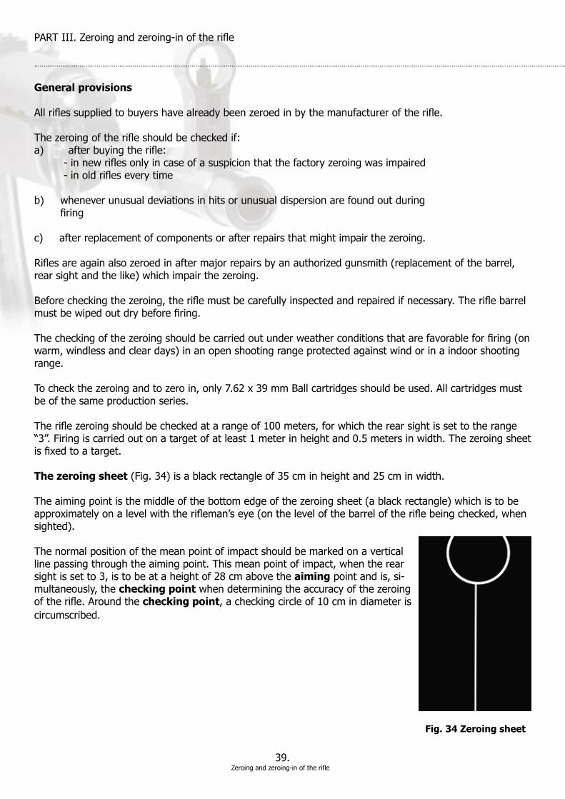
Theriflezeroingshouldbecheckedatarangeof100meters,forwhichtherearsightissettotherange“3”.Firingiscarriedoutonatargetofatleast1meterinheightand0.5metersinwidth.Thezeroingsheetisfixedtoatarget.
The zeroing sheet(Fig.34)isablackrectangleof35cminheightand25cminwidth.
Theaimingpointisthemiddleofthebottomedgeofthezeroingsheet(ablackrectangle)whichistobeapproximatelyonalevelwiththerifleman’seye(onthelevelofthebarreloftheriflebeingchecked,whensighted).
The normal position of the mean point of impact should be marked on a vertical linepassingthroughtheaimingpoint.Thismeanpointofimpact,whentherearsight is set to 3, is to be at a height of 28 cm above the aiming point and is, si-multaneously, the checking pointwhendeterminingtheaccuracyofthezeroingoftherifle.Aroundthechecking point, a checking circle of 10 cm in diameter is circumscribed.
Fig. 34 Zeroing sheet
40.Zeroingandzeroing-inoftherifle
Firingisdoneinapronepositionwithsupport.Abagfilledwithsandcanbeusedasasupport.Whenfir-ing,thelefthandholdingtheriflemustrestonthebag.
Procedure in checking rifle zeroing and zeroing in
Thezeroingriflemanloadsthemagazinewith4cartridgesandfires4shots,accuratelyandsteadilyaimedatthemiddleofthebottomedgeoftheblackrectangle,whileduringfire,neitherthepositionoftherifleman’sbodynorthatofhislefthandarechanged.
Afterterminationoffiring(ofthose4shots),thetargetisinspectedandthedispersiongroupingandtheposition of the mean point of impact evaluated. The rifle is considered as zeroed in if all the four hits -inanextremecase3ofthehits(ifonehitshowsagreatdeviationfromtheothers)–maybecoveredwithacircle of 18 cm in diameter and if, at the same time, the mean point of impact is not deviated by more than 5 cm to any side from the checking point.
Determination of mean point of impact
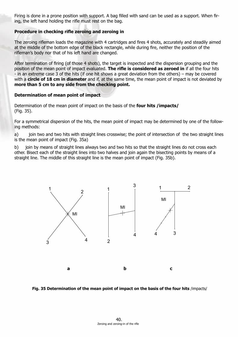
Determination of the mean point of impact on the basis of the four hits /impacts/(Fig.35).
Forasymmetricaldispersionofthehits,themeanpointofimpactmaybedeterminedbyoneofthefollow-ingmethods:
a) jointwoandtwohitswithstraightlinescrosswise;thepointofintersectionofthetwostraightlinesisthemeanpointofimpact(Fig.35a)
b)joinbymeansofstraightlinesalwaystwoandtwohitssothatthestraightlinesdonotcrosseachother.Bisecteachofthestraightlinesintotwohalvesandjoinagainthebisectingpointsbymeansofastraightline.Themiddleofthisstraightlineisthemeanpointofimpact(Fig.35b).
Fig. 35 Determination of the mean point of impact on the basis of the four hits /impacts/
a b c

2
1
3
Fig. 36 Determination of the mean point of impact on the basis of the three hits /impacts/
Foranasymmetricaldispersionofthehits,themeanpointofimpactshallbedeterminedasfollows:1) jointwoarbitraryhits/impacts/withastraightlineandbisectthedistancebetween them
2) jointheobtainedpointwiththethirdhitanddividethedistancebetweentheminto three equal sections
3) jointhedividingpointthatisclosertothetwofirsthitswiththefourthhitanddivide thedistancebetweenthemintofourequalsections;thethirddividingpointstarting fromthefourthhitisthemeanpointofimpactsearchedfor(Fig.35c).
Ifoneofthefourhits/impacts/isconsiderablydeviatedfromtheothers,donottakeitintoaccountanduse three hits method.
The mean point of impact on the basis of the three hits(Fig.36)shallbedeterminedasfollows:1) joinanytwoofthehitswithastraightlineandbisectthestraightline
2) jointhemiddleofthisstraightlinewiththeremainingthirdhit
3) dividethisnewstraightlineintothreeequalsections;thedividingpointthatiscloser totheconnectinglineofthefirsttwohitsisthemeanpointofimpact.
41.Zeroingandzeroing-inoftherifle
Ifthehits/impacts/cannotbecoveredwithacircleof18cmindiameterorifthemeanpointofimpactisdeviated from the checking point to any side more than 5 cm, but not more than 12 cm, the cause of such a great dispersion or the cause of great deviations of the hits from the checking point should be found. Af-terfindingoutthecause,theauthorizedgunsmithshouldrepairtherifleandthefiringshouldberepeated.Iftheresultoftherepeatedfireisagainunsatisfactory,i.e.thehits cannot be covered with a circle of 18 cm in diameter or the mean point of impact is deviated from the checking point more than 12 cm,therifleshouldbetakentoaauthorizedgunsmithtobezeroedin.
Ifthedispersiongroupingoftheriflecomplieswiththespecifiedcondition(thehitsmaybecoveredwithacircleof18cmindiameter),butthedeviationofthemeanpointofimpactfromthecheckingpointisgreat-erthan5cm,butnotexceeding12cm,therifleshouldbetakentoaauthorizedgunsmithtocarryout,independence on the position of the mean point of impact, an appropriate displacement or correction of the frontsightforheight.Thefrontsightshouldbescrewedinabit(lowered)ifthemeanpointofimpactissituatedbelowthecheckingpoint,oritshouldbeunscrewedabit(raised)ifthemeanpointofimpactisabovethecheckingpoint.Thefrontsightpinshouldbedisplacedtotheleft(totheright)ifthemeanpointofimpactisontheleft(ontheright)fromthecheckingpoint.Byvaryingthepositionofthefrontsightandthroughrepeatedfiringsuchapositionofthefrontsightmustbeobtainedatwhichthedeviationofthemean point of impact from the checking point to any side does not exceed 5 cm.
Changingoftheheightofthefrontsightpinby1turn(0.5mm)ordisplacementofthefrontsightpintothesideby0.5mmchangesthepositionofthemeanpointofimpactby14cmwhenfiringat100meters.
Ifboththedispersiongroupingandthepositionofthemeanpointofimpactcomplywiththeabove-men-tionedrequirements,thecheckingoftheriflezeroingisfinished.
Ifthesidepositionofthefrontsightwaschangedwhenzeroingintherifle,anewgaugemarkonthefrontsight pin opposite the gauge mark on the front sight holder should be made. The old gauge mark on the frontsightpinshouldberemoved.Itisforbiddentostampanewgaugemarkonthefrontsightholder.Ifthepositionfortheheightofthefrontsightwasimpaired,adropoflacquershouldbeappliedagain.
Theresultanddataofthezeroing(checkingofzeroing)oftherifleshouldbewrittenonthezeroingsheet.
Rifle malfunctions and troubles impairing the zeroing
Inthecourseofusingtherifleorduringthecheckingofthezeroing,thefollowingmalfunctions,duetodisplacementofthemeanpointofimpact,mayoccur:a) Sidedisplacementofthefrontsightpin,frontsighttopbentorimpairedbyimpact –projectilesdeviatetothesidewhichisoppositetothatofthefrontsightdeviation.
b) Bentorbeveledrearsightleaf–projectilesdeviatetothesidetowhichtheback sight notch is deviated.
c) Muzzleofboredamagedbyimpact–projectilesdeviatetothesidewhich isoppositetothatwiththemuzzledamage.
43.Zeroingandzeroing-inoftherifle

Dispersionenlargementmaybecausedbythefollowingmalfunctionsortroubles:a) Sidewobblingoftherearsight;aftereveryshot,theleafmaybeinadifferent position,thuscausingenlargementofthedispersionforwidth.
b) Wobblingoftherearsightslide:theplungerlugdoesnotretaintheslideinasteady positionontheleaf;whenfiring,theslidespontaneouslychangesitspositiononthe leaf, thus causing enlargement of the dispersion for height.
c) Worn-out(widened)boreinboththemuzzleandthecartridgechamber.
d) Worn-out,roundedorcrumbled-offedgesofthefieldsofthebore.
e) Rustybore,pitscausedbyrust,scratchesinthebore.
Therifleshallbezeroedinby8shotswhen:a) themeanpointofimpactofthe8shotslieswithinacircleof8cmindiameter,with the checking point being the center of the circle
b) dispersionofthose8shotsmustliewithinacircleof20cmindiameterwhenmea suredfromthecentersofthemostdistanthits/impacts/.Ifoneofthehitsdeviates,itmay beomittedandthenthedispersionisthatmadeofthesevenhits/impacts/, but this dispersion must not exceed a circle of 20 cm in diameter, either. Themeasuringshouldbedoneinthesamewayasinthepreviouscaseandthe position of the mean point of impact is determined from those seven shots. Asadeviatedhit/impact/isconsideredsuchahitthatismoredistantfromthemean point of impact made of the remaining 7 shots than is the diameter of the circle circumscribed for the remaining seven shots
c) correctionofthefrontsightispermissiblewithintheextentofthedeviationofthe longitudinal axis of ± 0.5 mm and ± 1 mm for the height from the mean value of thefrontsight(54.6mmwhenmeasuredfromtheoppositeprojectionsofthefront sightholder).
The rifle is considered as zeroed if the mean point of impact lies within a circle of 8 cm in diameter and if it is possible to cover all 8 (or 7) hits /impacts/ with a circle of 20 cm in diameter.
43.Zeroingandzeroing-inoftherifle


