One objective of 3GPP in the development of the Evolved Packet System (EPS) wasthe move towards a "packet only architecture", as well on the RAN side as on theCN (core network) side. The E-UTRAN and Core architecture will be packet based,although provision is made to support real-time and conversational class traffic.Another aim was a simplified network structure and a minimization of "singlepoints of failure", which also leads to a more cost effective network architecture.UUTTRRAANNCCSS PPSSIMIMSSPPSSTTNN IPIP3G Release 5EE--UUTTRRAANNPPSSTTNN IPIPEPSEEvvoolvlveeddPPaacckkeett C CoorreeIMIMSS IMSoptionalIMSoptional
1.1 Introduction One objective of 3GPP in the development of the Evolved Packet System (EPS) was the move towards a "packet only architecture", as well on the RAN side as on the CN (core network) side. The E-UTRAN and Core architecture will be packet based, although provision is made to support real-time and conversational class traffic. Another aim was a simplified network structure and a minimization of "single points of failure", which also leads to a more cost effective network architecture.
UTRANUTRAN
CSCS PSPS
IMSIMS
IPIPPSTNPSTN
3G Release 5
E-UTRANE-UTRAN
IPIPPSTNPSTN
EPS
Evolved Packet CoreEvolved Packet Core
IMSIMS IMSoptionalIMS
optional
Fig. 1 Evolution of Network Architecture
SAE Network Architecture
NW1247
5
This chapter shall give an overview of the different network components. The interfaces in between all these components are described within an extra chapter later on in the same module. The main components of EPS are:
• eNB (evolved NodeB)
• MME (Mobility Management Entity)
• S-GW (Serving Gateway)
• PDN-GW (Packet Data Network Gateway)
• PCRF (Policy and Charging Rules Function)
• HSS (Home Subscriber Server)
E-UTRANE-UTRAN
eNBeNB
S-GWS-GW
MMEMME
EPC
eNBeNB
C-Plane
U-PlanePDN GW
PDN GW
PCRFPCRF
HSS
Fig. 2 Evolved Packet System - Main components
SAE Network Architecture
NW1247
6
1.2 Evolved NodeB (eNB) The evolved RAN for LTE consists of one type of logical node, the eNodeB (eNB). The eNB supports the LTE air interface and deals with all radio-interfaced functions:
• Functions for Radio Resource Management (RRM): Radio Bearer Control, Radio Admission Control, Connection Mobility Control, Dynamic allocation of resources to UEs in both uplink and downlink (scheduling);
• IP header compression and encryption of user data stream;
• Selection of an MME at UE attachment when no routing to an MME can be determined from the information provided by the UE;
• Routing of User Plane data towards Serving Gateway;
• Scheduling and transmission of paging messages (originated from the MME);
• Scheduling and transmission of broadcast information (originated from the MME or O&M);
• Measurement and measurement reporting configuration for mobility and scheduling;
As the eNB initiates connections on the air interface, assigns air-interface resources, performs scheduling and - with the help of the X2 interface - can initiate and complete for example handovers, the RNC that UMTS used is now unnecessary. The eNB is directly connected to the Core Network using the S1 interface. The functions which were formerly based in the RNC are now handled mainly by the eNB. The eNB being the only entity of the E-UTRAN supports all the functions in a typical radio network such as Radio Bearer Control, Mobility Management, Admission control and scheduling. The Access Stratum (comprising all radio resource control functions) resides completely at the eNB.
SAE Network Architecture
NW1247
7
eNB
RB Control
Connection Mobility Control.
eNB Measurement Configuration & Provision
Dynamic Resource Allocation (Scheduler)
PDCP
PHY
MAC
Inter Cell RRM
Radio Admission Control RLC
RRC
Fig. 3 Functions of eNB
SAE Network Architecture
NW1247
8
1.3 MME - Mobility Management Entity The MME manages mobility, UE identities and security parameters. It is in charge of all the control plane (C-Plane) functions related to subscriber and session management The MME hosts the following functions:
• Non Access Stratum (NAS) signalling
• NAS signalling security
• Inter CN node signalling for mobility between 3GPP access networks (terminating S3)
• UE-Reachability in ECM-Idle state (including control and execution of paging retransmission)
• Tracking Area list management (for UE in idle and active mode)
• PDN GW and Serving GW selection
• MME selection for handovers with MME change
• SGSN selection for handovers to 2G or 3G 3GPP access networks
• Roaming (S6a towards home HSS)
• Authentication
• Bearer management functions including dedicated bearer establishment
• Lawful interception of signalling traffic
• Warning message transfer function (including selection of apropriate eNB)
• UE Reachability procedures The NAS procedures, especially the connection management procedures, are very similar to UMTS. The main change is that EPS allows the concatenation of several procedures for a faster establishment of the connection and of the bearers. Note: The MME and the Serving-GW may be implemented on one physical node or on separate nodes.
SAE Network Architecture
NW1247
9
internet
MME
S1
E-UTRAN EPC
Roaming
Idle StateUE Reachability
NAS Signalling
S-GW & PDN-GWSelection
EPS Bearer Control
Authentication
S-GW PDN-GW
Fig. 4 MME - Mobility Management Entity
SAE Network Architecture
NW1247
10
1.4 Gateways In EPS two logical gateways exist:
• the Serving Gateway (S-GW) and
• the Packet Data Network Gateway (PDN-GW). MME and S-GW may be implemented in one physical node or on separate physical nodes.
1.4.1 S-GW (Serving Gateway) The Serving GW terminates the interface towards E-UTRAN. Each UE is - at a given point of time - exactly associated with a single S-GW. The S-GW routes and forwards user data packets, while also functioning as the mobility anchor for the user plane during inter-eNB handovers and as the anchor for mobility between LTE and other 3GPP technologies. The interface between S-GW and PDN-GW (S5 or S8 for roaming cases) can be based on GTP or PMIP (Proxy Mobile IP). The S-GW functionality includes:
• the local Mobility Anchor point for inter-eNodeB handover;
• sending of one or more "end marker" to the source eNodeB, source SGSN or source RNC immediately after switching the path during inter-eNodeB and inter-RAT handover, especially to assist the reordering function in eNodeB
• Mobility anchoring for inter-3GPP mobility (terminating S4 and relaying the traffic between 2G/3G system and PDN GW)
• ECM-IDLE mode downlink packet buffering and initiation of network triggered service request procedure
• Lawful Interception
• Packet routeing and forwarding
• Transport level packet marking in the uplink and the downlink, e.g. setting the DiffServ Code Point, based on the QCI of the associated EPS bearer
• Accounting on user and QCI granularity for inter-operator charging
• UL and DL charging per UE, PDN, and QCI (e.g. for roaming with home routed traffic)
• Interfacing Offline Charging System (OFCS) according to charging principles and through reference points.
SAE Network Architecture
NW1247
11
Note: Connectivity to a GGSN is not supported.
internet
S-GW
E-UTRAN EPC
PDN-GW
MME
S5 / S8
S11
Mobility Anchor point for X2-HO
Mobility anchoring forinter-3GPP mobility
ECM-idle mode DLpacket buffering
Packet routeing and forwarding
Accounting for inter-operator charging
Fig. 5 Serving - GW Functions
SAE Network Architecture
NW1247
12
1.4.2 PDN-GW (Packet Data Network Gateway) The PDN-GW terminates the SGi interface towards the PDN. The P-GW provides connectivity to the UE to external packet data networks by being the point of exit and entry of traffic for the UE. If a UE is accessing multiple PDNs, there may be more than one PDN-GW for that UE. The PDN-Gateway hosts the following functions (supported for GTP and for PMIP):
• Per-user based packet filtering (by e.g. deep packet inspection)
• Lawful Interception
• UE IP address allocation
• Transport level packet marking in the uplink and downlink, e.g. setting the DiffServ Code Point, based on the QCI of the associated EPS bearer;
• UL and DL service level charging
• Interfacing OFCS through according to charging principles and through reference points
• UL and DL service level gating control
• UL and DL service level rate enforcement (e.g. by rate policing/shaping per SDF)
• UL and DL rate enforcement based on APN-AMBR (e.g. by rate policing/shaping per aggregate of traffic of all SDFs of the same APN that are associated with Non-GBR QCIs)
• DL rate enforcement based on the accumulated MBRs of the aggregate of SDFs with the same GBR QCI (e.g. by rate policing/shaping)
• DHCPv4 (server and client) and DHCPv6 (client and server) functions
• The network does not support PPP bearer type in this version of the specification. Pre-Release 8 PPP functionality of a GGSN may be implemented in the PDN GW
• packet screening.
SAE Network Architecture
NW1247
13
Additionally the PDN-GW includes the following functions for the GTP-based S5/S8
• UL and DL bearer binding
• UL bearer binding verification
• Neighbor Discovery for IPv6 (see RFC 4861 for more details) The PDN-GW provides PDN connectivity to both GERAN/UTRAN only UEs and E-UTRAN capable UEs using any of E-UTRAN, GERAN or UTRAN. The PDN-GW provides PDN connectivity to E-UTRAN capable UEs using E-UTRAN only over the S5/S8 interface.
internet
PDN-GW
E-UTRAN EPC
S-GW
MME
S5 / S8
S11
Per-user packet filtering
Lawful interception
UE IP addressallocation
DSCP setting forUL/DL data
DHCP functions
Packet screening
Fig. 6 PDN-GW Functions
SAE Network Architecture
NW1247
14
E-UTRANE-UTRAN
S-GWS-GW
EPC
PDN-GWPDN-GW
S5S5
PDN-GWPDN-GW
S5S5
S1S1
SGiSGi
SGiSGi
IMSIMS
InternetInternet
Fig. 7 S5 connectivity to multiple packet networks
SAE Network Architecture
NW1247
15
1.5 PCRF - Policy and Charging Rules Function
1.5.1 General In general terms, PCRF is the policy and charging control element. PCRF functions are described in more detail in TS 23.203. PCRF encompasses policy control decision and flow based charging control functionalities. The PCRF provides network control regarding the service data flow detection, gating, QoS and flow based charging (except credit management) towards the PCEF. Furthermore PCRF authorizes QoS resources. The PCRF uses the service information received from the AF (e.g. SDP information or other available application information) and/or the subscription information received from the SPR to calculate the proper QoS authorization (QoS class identifier, bitrates). The PCRF may also take into account the requested QoS received from the PCEF.
provides policy control decisionsflow based charging control functionsdecides how a certain SDF is handled by PCEF provides QoS rules for SDF based upon TFT
More details in TS 23.203
Fig. 8 PCRF - Policy and Charging Rules Function
SAE Network Architecture
NW1247
16
1.5.2 PCRF Scenarios In a non-roaming scenario, there is only a single PCRF in the HPLMN (Home PLMN) associated with one UE's IP-CAN session. The PCRF terminates the Rx interface and the Gx interface. In a roaming scenario with local breakout of traffic there may be two PCRFs associated with one UE's IP-CAN session:
• H-PCRF that resides within the H-PLMN;
• V-PCRF that resides within the V-PLMN.
1.5.2.1 Home PCRF (H-PCRF) The functions of the H-PCRF include:
• Termination of the Rx reference point for home network services;
• Termination of the S9 reference point for roaming with local breakout;
• Association of sessions established over the multiple reference points (S9, Rx), for the same UE's IP-CAN (connectivity access network) session (PCC (Policy Charging Control) session binding).
1.5.2.2 Visited PCRF (V-PCRF) The functions of the V-PCRF include:
• Termination of the Gx and S9 reference points for roaming with local breakout;
• Termination of Rx for roaming with local breakout and visited operator's Application Function.
Note: The PDN-GW may also interact with a AAA server over the SGi interface. This AAA Server may maintain information associated with UE access to the EPC and provide authorization and other network services. This AAA Server could be a RADIUS or Diameter Server in an external PDN network. This AAA Server is logically separate from the HSS and the 3GPP AAA Server.
SAE Network Architecture
NW1247
17
E-UTRANE-UTRAN
eNBeNB
S-GWS-GW
MMEMME
HPLMN
eNBeNB
X2X2
S1-CS1-C
PDN-GWPDN-GWS1-US1-U
S11S11
S5S5
HSSS6aS6a
SGiSGi Home Operator PDN
Home Operator PDN
PCRFPCRF
Home Operators IP
Services(e.g. IMS)
Home Operators IP
Services(e.g. IMS)
GxGx
RxRx
Fig. 9 Non-Roaming Architecture
E-UTRANE-UTRAN
eNBeNB
S-GWS-GW
MMEMME
VPLMN
eNBeNB
X2X2
S1-CS1-C
PDN-GWPDN-GWS1-US1-U
S11S11
S5S5
HSSS6aS6a
SGiSGi
Visited Operator PDN
Visited Operator PDN
V-PCRFV-PCRF
Home Operators IP
Services(e.g. IMS)
Home Operators IP
Services(e.g. IMS)
GxGx
H-PCRFH-PCRF
RxRx
S9S9
HPLMN
Fig. 10 Roaming Architecture for local breakout
SAE Network Architecture
NW1247
18
1.6 HSS - Home Subscriber Server The HSS is the master database for the PLMN. It incorporates the functions of the HLR (Home Location Register) and of the AuC (Authentications Center). HLR The HLR part is responsible for storing and updating when necessary the database containing all the user subscription information. AuC The AuC part of the HSS is in charge of generating security information from user identity keys and transferring them to the HLR and the respective nodes in the network.
internet
HSS
E-UTRAN EPC
S-GW
MME
S5 / S8
S11
Storing and updatingof user subscriptioninformation (HLR)
Generating securityinformation from user
identity keys and forwarding them to
HLR (AuC)
PDN-GW
S6a
SGi
Fig. 11 Home Subscriber Server (HSS) functions
SAE Network Architecture
NW1247
19
2 EPS Interfaces
SAE Network Architecture
NW1247
20
2.1 Overview A key feature of the EPS is the separation of the network entity that performs control-plane (C-Plane) functionality (Mobility Management Entity - MME) from the network entity that performs user-plane (U-Plane) functionality (Serving GW) with a well defined open interface between them (S11).
E-UTRANE-UTRAN
eNBeNB
S-GWS-GW
MMEMME
EPC
eNBeNB
X2X2
S1-MMES1-MME
S1-US1-U
C-Plane
U-Plane
PDN GW
PDN GW
S5S5
S11S11
PCRFPCRF
GxGx
HSSS6aS6a
SGiSGi IMS
SGSNSGSN
S3S3
RxRx
Fig. 12 Evolved Packet System - Interfaces
SAE Network Architecture
NW1247
21
2.2 X2 Interface The eNB are connected to each other by the X2 interface. The X2 interface is optional and provides a logical IP-based interface between adjacent eNBs for handover and RRM tasks. In LTE a handover is preferably performed via a source and a target base station. The X2 Interface is a logical interface between two eNBs. The X2 Interface supports the following tasks:
• exchange of signalling information between two eNBs during handover
• support of forwarding of PDUs between two eNBs during handover - support of X2 tunnels
3GPP states explicitly, that an inter-connection between eNBs supplied by different vendors shall be possible.
2.2.1 X2 Protocol Structure The protocol being used to transfer signalling information across the X2 interface is the so-called X2 Application Protocol (X2AP). The X2AP is terminated by the two eNBs inter-connected via the X2 interface.
SAE Network Architecture
NW1247
22
E-UTRANE-UTRAN
eNBeNB
S-GWS-GW
MMEMME
EPC
eNBeNB
X2X2
S1-MMES1-MME
S1-US1-U
C-Plane
U-PlanePDN GW
PDN GW
PCRFPCRF
HSS
Fig. 13 X2 - Interface
X2
eNB eNB
IP
UE UE
IP
L2
L1
SCTP
IP
L2
L1
SCTP
X2-AP X2-AP
Fig. 14 X2 - Interface - Control Plane
SAE Network Architecture
NW1247
23
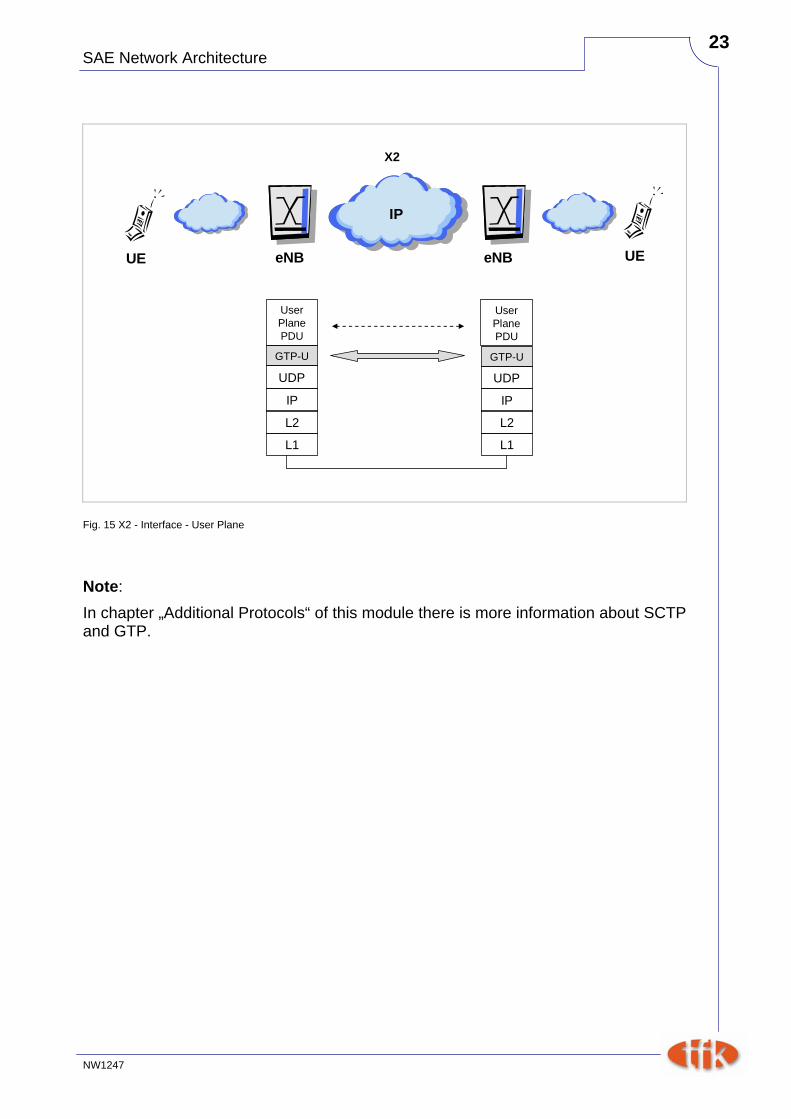
X2
eNB eNB
IP
UE UE
IP
L2
L1
GTP-U
IP
L2
L1
GTP-U
User PlanePDU
User PlanePDU
UDP UDP
Fig. 15 X2 - Interface - User Plane
Note: In chapter „Additional Protocols“ of this module there is more information about SCTP and GTP.
SAE Network Architecture
NW1247
24
2.2.2 X2 Functions The following functions are supported by the X2 Interface:
Intra LTE-Access-System Mobility Support for EPS ConnectionManagement - CONNECTED UE
Context transfer from source eNB to target eNBControl of user plane transport bearers between source eNB and targeteNBHandover cancellationUE context release in source eNB
General X2 management and error handling functionsError indicationReset
Application level data exchange between eNBsTrace functions
Fig. 16 Functions X2 Interface
SAE Network Architecture
NW1247
25
2.2.3 Intra LTE-Access-System mobility X2 is an optional Interface. Intra-E-UTRAN mobility is therefore possible
• with X2 support
• without X2 support
2.2.3.1 Handover Request In case of a eNB handover with X2 support, the handover is initiated by the source eNB by sending the "Handover Request" message to the target eNB.
1. Handover Request
2. Handover RequestAcknowledge
SourceeNB
Target eNB
3. RRC ConnectionReconfiguration
4. DL U-Plane PDUForwarding
(incl. „DL Forwarding“)
Fig. 17 Initiation of Handover (with X2 support)
The Target eNB acknowledges with a "Handover Request Acknowledge" Message and sends and "RRC Connection Reconfiguration" message towards the UE. On reception of the "Handover Request Acknowledged", the source eNB forwards all buffered DL U-Plane data to the target eNB. Note: The proposal for forwarding of downlink packets is included as "DL Forwarding" Information Element in the "Handover Request" Message.
SAE Network Architecture
NW1247
26
The control function of U-plane transport bearers between source eNB and target eNB allows the establishment and release of transport bearers between source and target eNB to allow for data forwarding in UL and DL.
2.2.3.2 SN Status Transfer In the next step, the source eNB transfers the SN Status transfer (Sequence Number Status Transfer) to the target eNB:
5. SN Status Transfer
SourceeNB
Target eNB
SN Status Transfer of E-RAB includesUL and DL PDCP Sequence Errors
Hyper Frame Number Receiver Status
Fig. 18 SN Status Transfer
The purpose ot the SN Status Transfer procedure is to transfer the UL and DL PDCP (Packet Data convergence Protocol) Sequence Numbers and Hyper Frame Number receiver status of the respective E-RABs to the target eNB.
SAE Network Architecture
NW1247
27
2.2.3.3 UE Context Release After the U-plane tunnel in the EPC is switched and RRC reconfiguration took place in the UE, the target eNB sends the "UE Context Release" Message to the source eNB to signal to the source eNB that the control plane resources for the UE context can be released.
6. UE Context Release
SourceeNB
Target eNB
C-Plane resources for UE contextcan be released
Data forwarding will be stoppedafter reception of „End Markers“
Fig. 19 UE Context Release
Data forwarding will be stopped after reception of the respective "End Markers" and Handover procedure is completed. For further details pls. refer to module “SAE Procedures”.
SAE Network Architecture
NW1247
28
2.2.4 Load Management and Inter-Cell-Interference Coordination
This function allows to exchange overload and traffic load information between eNBs. This information may be spontaneously sent to selected neighbour eNBs, or reported as configured by a neighbour eNB. The Inter-cell interference coordination function allows keeping inter-cell interference under control. Neighbouring eNBs exchange appropriate information to enable them to make radio resource assignments such that interference is mitigated. To transfer load and interference co-ordination information, the message "Load Information" is used:
Load Information
Load information may includeUL Interference Overload Indication IEUL High Interference Indication IERelative Narrowband Tx Power (RNTP)
eNB 1 eNB 2
Fig. 20 Load Information
The Load Information can have three different characteristics:
• UL Interference Overload Indication IE.
• UL High Interference Indication IE.
• Relative Narrowband Tx Power (RNTP).
SAE Network Architecture
NW1247
29
I) UL Interference Overload Indication IE Possible values are:
• high interference
• medium interference
• low interference The report is delivered per Physical Resource Block (PRB). It indicates the interference level experienced by the sending eNB on some resource blocks. The receiving eNB may take such information into account when setting its scheduling policy. The indication is valid until reception of a new "Load information" message carrying an update of the same IE.
- high, medium or low interferencereceiving eNB may use this info for scheduling
eNB 1 eNB 2
Fig. 21 UL Interference Overload Indication IE
SAE Network Architecture
NW1247
30
II) UL High Interference Indication IE Possible values per PRB are:
• High Interference sensitivity
• Low interference sensitivity. This IE indicates, per PRB, the occurrence of high interference sensitivity, as seen from the sending eNB. The receiving eNB should try to avoid scheduling cell edge UEs in its cells for the concerned PRBs. The information about the affected cell is included in the message. The indication is valid until reception of a new "Load information" message carrying an update of the same IE. Note: The interaction between the indication of UL Overload and UL High Interference is implementation specific.
Load Information
sending eNB indicates high interference sensitivitypossible values:
- high or low interference sensitivityreceiving eNB should try to avoid scheduling cell edge UEs
eNB 1 eNB 2
Fig. 22 UL High Interference Indication IE
SAE Network Architecture
NW1247
31
III) Relative Narrowband Tx Power (RNTP) IE Possible values:
• RNTP per PRB
• RNTP Threshold
• Number of Cell-specific Antenna Ports
• PDCCH (Physical Data Control Channel) Interference Impact This IE provides an indication on DL power restriction per PRB in a cell and other information needed by a neighbour eNB for interference aware scheduling. It indicates, per PRB, whether downlink transmission power is lower than the value indicated by the RNTP Threshold IE. The receiving eNB may take such information into account when setting its scheduling. The indication is valid until reception of a new "Load information" message carrying an update of the same IE.
Load Information
sending eNB indicates DL power restrictions in a cellpossible values:
- RNTP per PRB, RNTP Threshold, etc.indicates e.g. whether DL transmission power is lower than RNTP threshold
eNB 1 eNB 2
Fig. 23 Relative Narrowband Tx Power (RNTP) IE
SAE Network Architecture
NW1247
32
2.2.5 General X2 Management and error function handling function
The "Error Indication" function is used to report general error situations. It reports detected errors in incoming message (if is cannot be reported by an approprate failure message). The "Reset" function is used to inform another eNB2 that eNB1 has recovered from an abnormal failure and that all the contexts related to eNB1 and stored in eNB2 shall be deleted, and the associated resources released. The purpose this procedure is to align the resources in eNB1 and eNB2 in the event of an abnormal failure.
2.2.6 Application level data exchange between eNBs This function is used to exchange application level data between two eNBs when an X2 connection is setup and to update this information at any time.
2.2.7 Trace functions Trace recording sessions on E-UTRAN interfaces are initiated by the EPC. This information is also forwarded to the target eNB during handover. Note:
The "Resource Status Request" message is defined initiate measurement in the neighbouring eNB2 and to report them to the requesting eNB1 in the "Resource Status Update" message, according to the parameters given in the message. The message structure of the "Resource Status Update" message is not yet defined.
SAE Network Architecture
NW1247
33
2.3 S1 Interface The eNBs are connected by means of the S1 interface to the EPC (Evolved Packet Core), more specifically to the MME (Mobility Management Entity) by means of the S1-MME (or S1-C) and to the Serving Gateway (S-GW) by means of the S1-U.
2.3.1 S1-Flex S1 flex describes the concept that S1 interface supports a many-to-many relation between MMEs respectively Serving Gateways and eNBs. This concept provides support for network redundancy and load sharing of traffic across network elements in the Core network, the MME and the SGW, by creating pools of MMEs and SGWs and allowing each eNB to be connected to multiple MMEs and SGWs in a pool.
E-UTRANE-UTRAN
eNBeNB
S-GWS-GW
MMEMME
EPC
eNBeNB
S-GWS-GW
MMEMMES1-MMES1-MME
S1-US1-U
X2X2
Fig. 24 S1 flex
SAE Network Architecture
NW1247
34
2.3.2 Pool Area Concept The S1 flex introduces the concept of pool area. A pool area is an area which a terminal may move into without a need to change its serving core network node. It consists of a predefined set of eNBs, corresponding to one or several Tracking Areas. A pool area can be served by one or several MME/S-GW.
MMES-GWMMES-GW
S1 Flex
MMES-GWMMES-GW
eNBeNB
eNBeNBeNBeNB
eNBeNB
eNBeNB
Pool Area 1
Pool Area 2
eNBeNB
MMES-GWMMES-GWMME
S-GWMMES-GW
eNBeNB
Traditional 1-to-n
S1
RNCRNCRNCRNC
RNCRNC
RNCRNCRNCRNC
SGSNSGSN SGSNSGSNIu
Fig. 25 S1 flex concept vs. traditional access-core connectivity
SAE Network Architecture
NW1247
35
Advantages of using the S1 flex feature/pool concepts are as follows:
reduction of inter-core network node handover / Tracking Area Updatessupport of network sharing architectures enabling redundant pool area coverage of MME/S-GW in case of core node failuremore efficient capacity management and load sharing is enabled
Fig. 26 Advantages of S1 flex
SAE Network Architecture
NW1247
36
Tracking Area Basically a Tracking Area (TA) is definded as a set of contiguous cells. The identity of the TA the cell belongs to, or TAI (Tracking Area Identity), is part of the system information broadcast on the BCCH (Broadcast Control Channel). As in the 3GPP definition, Tracking Areas may overlap each other. When the network needs to join the terminal, a paging message is sent in all the cells which belong to the Tracking Area. The dimensioning of TA is a typical network-engineering issue, which results from a tradeoff between network signalling load and radio paging load:
• If TA are too small, terminal moves will result in a large number of TA update procedures and high signalling load. This issue can be worked out by increasing the size of the TA.
• On the other hand, if the TA are too large, all the cells within the TA will have to cope with a high traffic load on the Paging channel. Since the Packet Core does not know the idle terminal location with more accuracy than the TA, one single mobile-terminated call will generate a paging message in each cell of the TA in which the terminal is located.
In practice, Tracking Areas are dimensioned according to the estimation of IDLE mode terminal density. In hot-spot, or high-speed, dense urban areas, TA are usually small so as to limit the paging load. In contrast, in rural or low-speed, dense areas, TA size can be increased without compromising the network signalling load. The current terminal TA is signalled to the core under three circumstances:
• At initial registration, the terminal communicates to the Core Network its current Tracking Area.
• When the terminal changes zones, as a result of subscriber move within the network, the new TA is updated in order to keep the packet-based core network updated.
• In addition, the current TA is periodically updated (or refreshed), even if it does not change, so that the packet core does not keep alive a context for a terminal which is no longer reachable in the network. This can happen if the terminal fails to de-register or suddenly runs out of coverage.
SAE Network Architecture
NW1247
37
UE at initial registrationUE changes zone (TA)Periodic update
Fig. 27 Reasons for TA signalling to core
SAE Network Architecture
NW1247
38
2.3.3 Protocol Structure The S1 interface is specified at the boundary between the E-UTRAN and the EPC. S1-AP services are divided into two groups:
• Non UE-associated services: They are related to the whole S1 interface instance between the eNB and MME utilizing a non UE-associated signalling connection.
• UE-associated services: They are specifically related to one UE. S1-AP functions that provide these services are associated with a UE-associated signalling connection that is maintained for the UE in question.
SAE Network Architecture
NW1247
39
S1-MME
eNB MME
IP
UE
IP
L2
L1
SCTP
IP
L2
L1
SCTP
S1-AP S1-AP
Radio
Fig. 28 S1-MME Interface - Control Plane
S1-U
eNB S-GW
IP
UE
IP
L2
L1
GTP-U
IP
L2
L1
GTP-U
User PlanePDU
User PlanePDU
UDP UDP
Fig. 29 S1-U - Interface - User Plane
Note: IP Differentiated Services code point marking shall be supported. The mapping between traffic categories and Diffserv code points shall be configurable by O&M based on QoS Class Identifier (QCI). Characteristics and others E-UTRAN traffic parameters. Traffic categories are implementation-specific and may be determined from the application parameters.
SAE Network Architecture
NW1247
40
2.3.4 S1-AP Functions The S1-Interface is used to perform the following functions:
Selection functions
Security functions
Service and network access function (NAS Transport, UE Tracing and Location Reporting function)
S1 UE Context management
Radio Access Bearer (E-RAB) management
S1 Link management
Mobility functions for UEs in LTE-active
Paging
S1 Load management
Fig. 30 S1-AP Functions
SAE Network Architecture
NW1247
41
2.3.4.1 Selection functions Selection or coordination functions include network sharing functions and MME node selection function in the eNB.
MME Selection Multiple MMEs can be grouped together in a pool to meet increasing signaling load in the network.The selection of a MME is based on network topology. A MME serves the UE's location and in case of overlapping MME service areas, the selection may prefer MMEs with service areas that reduce the probability of changing the MME. The interconnection of eNBs to multiple MME/Serving S-GWs is supported in the E-UTRAN/EPC architecture (see sub-chapter “Pool Area Concept”). Therefore a NAS node selection function is located in the eNB to determine the MME association of the UE, based on the UE’s temporary identifier, which was assigned to the UE by the MME. This functionality is located in the eNB only and enables proper routing via the S1 interface. On S1, no specific procedure corresponds to the NAS Node Selection Function. This functionality is located in the eNB to determine and establish an association between a given UE and one of the MME nodes that comprise the pool area the eNB belongs to. It then enables proper routeing via the S1-MME interface. When an eNB selects an MME, the selection shall achieve load balancing.
2.3.4.2 Security Security functions include radio interface ciphering function and data integrity functions.
2.3.4.3 Service and Network Access The NAS Signalling Transport function provides means to transport a NAS message for a specific UE on the S1 interface. The NAS EPC signalling data shall be transparently conveyed between the EPC and the UE. Over the S1 interface, the same S1 interface channel that is used for the E-UTRAN-EPC signalling shall be used.
SAE Network Architecture
NW1247
42
NAS supports
Mobility Management (MM)
eNB MME
IP
UE
IP
L2
L1
SCTP
IP
L2
L1
SCTP
S1-AP S1-AP
Radio
NAS
RLC
MAC
L1
PDCP
RRC
S1-MME
Relay
RLC
MAC
L1
PDCP
RRC
NAS
LTE-Uu
Fig. 31 S1 NAS functionality
SAE Network Architecture
NW1247
43
2.3.4.4 S1 UE Context Management Within each pool area, an UE is associated to one particular MME for all its communications during its stay in this pool area. This creates a context in this MME for the UE. The MME is selected by the NAS Node Selection Function in the first eNB form which the UE has entered the pool. UE context may include general UE Context (e.g. security context, roaming restrictions, UE capability information, etc.), E-RAB context (S-GW TEID, QoS information), etc. Related Procedures are for example Initial Context Setup procedure in case of an Idle-to-Active transition (to establish an S1UE context in the eNB, to setup the default IP connectivity, to setup one or more E-RABS and to transfer NAS signalling related information to the eNB if needed), S1 UE Context Release procedure or UE context Modification procedure. The Initial Context Setup Request is also used during the Attach Procedure.
PagingPaging
Random Access Procedure
NAS: Service Request NAS: Service Request
S1-AP: Initial Context Setup Request
RRC: Radio Bearer Setup
RRC: Radio Bearer Setup Complete
S1-AP: Initial Context Setup Response
eNB MMEUE
Fig. 32 Initial Context Setup Procedure - Transition Idle to Active Mode
SAE Network Architecture
NW1247
44
2.3.4.5 E-Radio Access Bearer (RAB) Management This overall functionality is responsible for setting up, modifying and releasing E-RABs once a UE context is available in the eNB, triggered by the MME. The release of E-RABs may be triggered by the MME or as well by the eNB. The objective of the E-RAB setup procedure is to assign resources on Uu and S1 for one or several E-RABs.
1. E-RAB Setup Request
2. E-RAB Setup Response
eNB MMES1-MME
Fig. 33 Radio Access Bearer (E-RAB) Setup Procedure
SAE Network Architecture
NW1247
45
2.3.4.6 S1 Link Management S1 Link Management functions include GTP-U tunnel management function as well as S1 Signalling link management function.
2.3.4.7 Mobility functions for UEs in LTE-active These mobility functions include support for Intra-LTE handover via S1-Interface and Inter-3GPP RAT handover. Intra-LTE Handover via S1-Interface The source eNB initiates the handover by sending the "Handover Required" message to the serving MME.
Handover Required
Handover Request
Handover Request Ack
Handover Command
Handover Notify
EPC Bearer Update
UE context Release command
UE Context Release complete
Target eNB
SourceeNB MME
S1- MME
RRC-Signalling to UE:UE performs HO
Fig. 34 Intra-LTE Handover via S1 (extract)
The MME then sends the "Handover Request" Message to the target eNB to reserve resources at the target eNB. The Source eNB sends via RRC a "Handover Command" message to the UE, which reacts with a "Handover Confirm" message to the target NB.
SAE Network Architecture
NW1247
46
The MME is then informed with the help of the "Handover Notify" message, that the UE has arrived to the target cell and the S1 handover has been successfully completed. The EPC Bearer is updated. Finally, the UE context at the source eNB is released.
2.3.4.8 Paging In order to re-establish a connection towards an UE in idle mode, the MME distributes a paging request to the relevant eNBs based on the tracking area (TA) where the UE is expected to be located. The paging request contains the UEs SAE-Temporary Mobile Subscriber Identity (S-TMSI).
Paging Request
eNB MME
Fig. 35 Paging function
SAE Network Architecture
NW1247
47
2.3.4.9 S1 Load Management This function is used by the eNB / MME to apply to several procedures:
• load balancing to distribute the traffic
• load re-balancing: to partially/fully offload an MME
• overload: to overcome a sudden peak in the loading of the MME.
2.3.4.9.1 Load Balancing The MME Load Balancing functionality permits UEs that are entering into an MME Pool Area to be directed to an appropriate MME in a manner that achieves load balancing between MMEs. This is achieved by setting a Weight Factor for each MME, such that the probability of the eNodeB selecting an MME is proportional to its Weight Factor. The Weight Factor is typically set according to the capacity of an MME node relative to other MME nodes. The Weight Factor is sent from the MME to the eNodeB via S1-AP messages.
Weight Factor a
eNB MME
UE can be removed from MME1 and assigned to MME2
e.g. O&M reasons
Weight Factor b
I) Load Balancing
II) Load Re-balancing
weight factor is proportional to probabilityof eNB selecting a specific MME
MME
Fig. 36 S1 Load Management
SAE Network Architecture
NW1247
48
2.3.4.9.2 Load Re-balancing The MME Load Re-balancing functionality permits UEs that are registered on an MME (within an MME Pool Area) to be moved to another MME. As an example for the use of the MME Load Re-balancing function, O&M related removal of one MME from an MME Pool Area can be considered. The eNodeBs may have their Load Balancing parameters adjusted beforehand (e.g. the Weight Factor is set to zero if all subscribers are to be removed from the MME, which will route new entrants to the pool area into other MMEs). In addition the MME may off-load a part of its subscribers with minimal impacts on the network and users. The load re-balancing can off-load part of or all the subscribers. To off-load ECM-CONNECTED mode UEs, the MME initiates the S1 Release procedure with release cause "load balancing TAU required". The S1 and RRC connections are released and the UE initiates a TAU and indicates to the eNB that the RRC establishment is for load balancing reasons. To off-load UEs which perform TA Updates or Attaches initiated in ECM-IDLE mode, the MME completes that procedure and the procedure ends with the MME releasing S1 with release cause "load balancing TAU required". The S1 and RRC connections are released and the UE initiates a TAU and indicates to the eNB that the RRC establishment is for load balancing reasons.
2.3.4.9.3 MME Overload Control The purpose of the Overload Start procedure is to inform an eNB to reduce the signalling load towards the concerned MME. The MME shall contain mechanisms for avoiding and handling overload situations. These can include the use of NAS signalling to reject NAS requests from UEs. In addition, under unusual circumstances, the MME shall restrict the load that its eNodeBs are generating on it if it is configured to enable the overload restriction. This can be achieved by the MME invoking the S1 interface overload procedure. To reflect the amount of load that the MME wishes to reduce, the MME can adjust the proportion of eNodeBs which are sent S1 interface OVERLOAD START message, and the content of the OVERLOAD START message. The MME should select the eNodeBs at random (so that if two MMEs within a pool area are overloaded, they do not both send OVERLOAD START messages to exactly the same set of eNodeBs). Using the OVERLOAD START message, the MME can request the eNB to:
• reject all RRC connection requests that are for non-emergency mobile originated PS services or for nonemergency mobile originated CS services for that MME
• reject all new RRC connection requests for EPS Mobility Management signalling (e.g. for TA Updates) for that MME
SAE Network Architecture
NW1247
49
• only permit RRC connection establishments for emergency sessions for that MME. When the MME has recovered and wishes to increase its load, the MME sends OVERLOAD STOP messages to the eNodeB(s). Upon receiving the message "Overload Stop", the eNB shall assume that the overload situation at the respective MME is solved and shall resume normal operation. Note: However, extreme care is needed to ensure that this load re-balancing does not overload other MMEs within the pool area. Only if the operator/O&M system is sure that there is spare capacity in the rest of the pool, the operator/O&M system might use the load re-balancing procedure to move some load off this MME.
Overload Start
Overload Stop
eNB MME
eNB MME
III) MME Overload Control
Fig. 37 S1 Load Management
SAE Network Architecture
NW1247
50
2.4 S11 Interface The S11 Interface is located between the MME and Serving GW. It supports bearer management, e.g. user attachment or service request. It is used to decompose the control und user plane functions between the MME and SGW. S11 is based on GTPv2-C.
S11
MME S-GW
IP
IP
L2
L1
UDP
IP
L2
L1
UDP
GTPv2-C
GTPv2-C
Fig. 38 S11 Interface - Control Plane
2.4.1 S11 functions Functions of S11 interface are mainly based on Tunnel Management. For example, in case of Intra-E-UTRAN Mobility with EPC Node Relocation, the User Plane tunnel needs to be switched. Therefore, after the target MME receives a "Relocation Request" message from the source MME, the target MME initiates a "Create Bearer Request" to the target S-GW:
SAE Network Architecture
NW1247
51
2. Create Bearer Request
3. Create Bearer Response
Target MME
Target S-GW
Source MME
1. Relocation Req
S10
S11
2. Create Bearer Request:
- IMSI, Bearer Context(s) with PDN-GW-@ and TEIDs for S5/S8,MME-@, etc.
3. Create Bearer Response:
- S-GW-@, Uplink TEID
Fig. 39 Create Bearer Request over S11
SourceeNB
Target eNB
SourceS-GW
SourceMME
Target MME
Target S-GW
PDN-GW
GTP-U
GTPv2-C
S10S11 S11
S5 S5
X2
SCTP
S1 S1
Fig. 40 Intra-E-UTRAN mobility with EPC relocation
SAE Network Architecture
NW1247
52
2.5 S10 Interface The S10 interface is located between MME and MME.
MME MME
IP
IP
L2
L1
UDP
IP
L2
L1
UDP
GTPv2-C
GTPv2-C
S10
Fig. 41 S10 Interface - Control Plane
SAE Network Architecture
NW1247
53
2.6 S5 Interface The S5 Interface is located between S-GW and P-GW.
S-GW PDN-GW
IP
IP
L2
L1
UDP
IP
L2
L1
UDP
GTPv2-C
GTPv2-C
S5 (or S8)
Fig. 42 S5 (or S8) Interface - Control Plane
S-GW PDN-GW
IP
IP
L2
L1
UDP
IP
L2
L1
UDP
GTP-U
GTP-U
S5 (or S8)
Fig. 43 S5 (or S8) Interface - User Plane
SAE Network Architecture
NW1247
54
2.7 S12 Interface S12 Interface is located between RNC and S-GW. Reference point between UTRAN and Serving GW for user plane tunneling when Direct Tunnel is established. It is based on the Iu-u/Gn-u reference point using the GTP-U protocol as defined between SGSN and UTRAN or respectively between SGSN and GGSN. Usage of S12 is optional. It is based on network operator configuration option.
RNC S-GW
IP
IP
L2
L1
UDP
IP
L2
L1
UDP
GTP-U
GTP-U
S12
Fig. 44 S12 - User Plane
SAE Network Architecture
NW1247
55
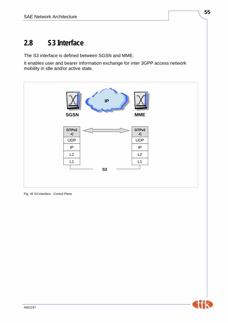
2.8 S3 Interface The S3 interface is defined between SGSN and MME. It enables user and bearer information exchange for inter 3GPP access network mobility in idle and/or active state.
SGSN MME
IP
IP
L2
L1
UDP
IP
L2
L1
UDP
GTPv2-C
S3
GTPv2-C
Fig. 45 S3 Interface - Control Plane
SAE Network Architecture
NW1247
56
2.9 S4 Interface The S4 interface is defined between SGSN and S-GW. It provides related control and mobility support between GPRS Core and the 3GPP Anchor function of Serving GW. In addition, if Direct Tunnel is not established, it provides the user plane tunneling.
SGSN S-GW
IP
IP
L2
L1
UDP
IP
L2
L1
UDP
GTPv2-C
S4
GTPv2-C
Fig. 46 S4 Interface - Control Plane
SAE Network Architecture
NW1247
57
2.10 S6a Interface The S6a Interface is located between MME and HSS.
MME HSS
IP
IP
L2
L1
SCTP
IP
L2
L1
SCTP
Dia-meter
Dia-meter
S6a
Fig. 47 S6a - Interface - Control Plane
The DIAMETER protocol is specified in RFC 3588.
SAE Network Architecture
NW1247
58
2.11 Summary of User and Control Plane
2.11.1 User Plane The following figure gives a summary about the protocols running on U-plane between UE and PDN-GW.
eNB S-GW
IP
UE
UDP/IP
L2
L1
GTP-U
UDP/IP
L2
L1
GTP-U
Radio
RLC
MAC
L1
PDCP
S1-U
Relay
RLC
MAC
L1
PDCP
IP
Appli-cation
LTE-Uu
PDN-GW
IP
IP
UDP/IP
L2
L1
GTP-U
UDP/IP
L2
L1
GTP-URelay
S5/S8
Fig. 48 U-Plane between UE and PDN-GW
SAE Network Architecture
NW1247
59
2.11.2 Control Plane The following figure gives a summary about the protocols running on C-plane between UE and PDN-GW.
eNB S-GW
IP
UE
Radio
PDN-GW
IP
MME
IP
IP
L2
L1
SCTP
IP
L2
L1
SCTP
S1-AP S1-AP
NAS
RLC
MAC
L1
PDCP
RRC
S1-MME
Relay
RLC
MAC
L1
PDCP
RRC
NAS
LTE-Uu
UDP
IP
L2
L1
GTP-C
UDP
IP
L2
L1
GTP-C
S11
UDP
IP
L2
L1
GTP-C
UDP
IP
L2
L1
GTP-C
S5
Fig. 49 C-Plane between UE and PDN-GW
SAE Network Architecture
NW1247
60
2.12 Additional Protocols
2.12.1 Stream Control Transmission Protocol (SCTP)
2.12.1.1 General SCTP (Stream Control Transmission Protocol) was defined by the IETF Signaling Transport (SIGTRAN) working group in 2000. RFC 4960 and RFC 3286 provide more detailed information about SCTP. SCTP is a reliable connection-oriented transport protocol which is very similar to the well known and widely used TCP. As TCP, SCTP implements congestion and flow control, detection of data corruption, loss or duplication of data and supports a selective retransmission mechanism. Unlike TCP, SCTP is a message-oriented protocol.
2.12.1.2 SCTP Association As TCP, SCTP works in connected mode, so that an association (the actual SCTP term for a connection) needs to be set up between peers before data transmission can occur. In SCTP, an association is defined by a 4-tuple:
• Source IP
• Source Port
• Destination IP
• Destination Port
2.12.1.3 SCTP Features When comparing TCP and SCTP from a functional perspective, SCTP provides two key features which TCP does not support:
• multi-streaming.
• multi-homing. Additionally SCTP provides a built-in cookie-based protection against denial of service (DoS) attacks.
SAE Network Architecture
NW1247
61
2.12.1.3.1 SCTP Multi-Streaming The term multi-streaming refers to the capability of SCTP to transmit several independent streams of user data in parallel, for example transmitting Web page images together with the Web page text. In essence, it is the bundling of several connections into a single SCTP association, operating on messages (or chunks) rather than bytes. But when a transmission error occurs on one of the stream, it does not affect data transmission on the other streams. In contrast, TCP only provides one stream for a given connection between IP peers, which may cause additional data transmission delay when a packet or group of packets is lost. When a transmission loss occurs on a TCP connection, packet delivery is interrupted until the missing parts are restored, as in-sequence data delivery (or data sequence preservation) is a key TCP feature.
2.12.1.3.2 SCTP Multi-Homing The other advantage of SCTP in comparison to TCP is multi-homing. This feature means that one (or both) endpoint(s) of a connection can consist of more than one IP address, enabling transparent fail-over between redundant network paths. Multi-homing allows a SCTP endpoint to be reached through multiple IP addresses. This mechanism provides redundancy. It improves the resilience when network failures occur. In case of transmission errors, retransmitted packets may be sent to alternate addresses in order to increase the probability of successful transmission.
similar to TCP (flow control, reliability, SACK)message-orientedassociation based:
- source IP- source port- destination IP- destination port
supports multi-streaming (several streams within one association)supports multi-homing (multiple IP-@ as association endpoints)built-in cookie-based DoS protection
Fig. 50 Stream Control Transmission Protocol (SCTP)
SAE Network Architecture
NW1247
62
2.12.1.3.3 Cookie-based DoS protection The SYN flood attack is special kind of attack, causing a TCP endpoint to receive a connection request to reserve a resource context and memory for some incoming connections that will never be fully set up by the initiator. At some point, this process can exhaust all memory or processing resources in the receiver. To counter this, SCTP makes use of a cookie mechanism. The actual seizure of association resource is only performed once the initiator successfully answers with the correct cookie. On reception of the INIT message, the receiver builds a cookie and sends it to the initiator using the INlT ACK message. To enable the association, the initiator must answer a COOKIE ECHO containing the same cookie as received in the INITACK. Resource reservation related to the association is only performed by the 'B' side on reception of a COOKE ECHO. At the end, the COOKIE ACK is sent back to the initiator to acknowledge the association setup. Resource attack is prevented by building the cookie in a special way. In principle, the receiver of the INIT message is using a secret key and a hash-mechanism to create it, so that on reception of the COOKIE ECHO, it can then validate that the cookie was actually previously generated by the receiver. This protection is based on the fact that the receiving entity does not reserve resources or keep context pending during the INIT phase. Resource activation is only performed when a valid COOKIE ECHO message is received.This assumes the rogue initiator does not process the answers, which is generally the case for DoS attacks.
INIT
INIT ACK (cookie X)
Initiator(e.g. attacker)
Other endpoint(e.g. S-GW)
COOKIE ECHO (cookie X)
COOKIE ACK
Cookie X is based on secret key and hash algorithm
Fig. 51 SCTP- Cookie based DoS protection
SAE Network Architecture
NW1247
63
2.12.2 GTP GPRS Tunnel Protocol (GTP) is specified in TS 29.281 (GTPv1-U) and in TS 29.274 (GTPv2-C) of 3GPP.
2.12.2.1 General GTP tunnels are used between two nodes communicating over a GTP based interface, to separate traffic into different communication flows. A GTP tunnel is identified in each node with
• a TEID (Tunnel Endpoint ID)
• an IP address and
• a UDP port number. The receiving end side of a GTP tunnel locally assigns the TEID value the transmitting side has to use. The TEID values are exchanged between tunnel endpoints using GTP-C or SCTP messages. The criteria defining when the same or different GTP tunnels shall be used between to nodes differs between the control and the user plane, and also between interfaces.
2.12.2.2 GTPv1-U GTP-U is based on GTP version 1 (GTPv1).
GTPv1 Header The GTPv1 header is a variable length header used for GTP-U protocols. The minimum length of the GTP header is 8 bytes. There are three flags that are used to signal the presence of additional optional fields:
• PN flag
• S flag
• E flag. The PN flag is used to signal the presence of N-PDU Numbers. The S flag is used to signal the presence of the GTP Sequence Number field. The E flag is used to signal the presence of the Extension Header field, used to enable future extensions of the GTP header defined in this document, without the need to use another version number.
SAE Network Architecture
NW1247
64
If one or more of these three flags are set, the fields Sequence Number, N-PDU and Extension Header shall be present. The sender shall set all the bits of the unused fields to zero. The receiver shall not evaluate the unused fields. Always present fields:
• Version field: This field is used to determine the version of the GTP protocol. The version number shall be set to "1".
• Protocol Type (PT): This bit is used as a protocol discriminator between GTP (when PT is "1") and GTP' (when PT is "0"). Note that the interpretation of the header fields may be different in GTP' than in GTP.
• Extension Header flag (E): This flag indicates the presence of a meaningful value of the Next Extension Header field. When it is set to "0", the Next Extension Header field either is not present or, if present, shall not be interpreted. When it is set to "1", the Next Extension Header field is present, and shall be interpreted, as described below in this section.
• Sequence number flag (S): This flag indicates the presence of a meaningful value of the Sequence Number field. When it is set to "0", the Sequence Number field either is not present or, if present, shall not be interpreted. When it is set to "1", the Sequence Number field is present, and shall be interpreted, as described below in this section.
• N-PDU Number flag (PN): This flag indicates the presence of a meaningful value of the N-PDU Number field. When it is set to "0", the N-PDU Number field either is not present, or, if present, shall not be interpreted. When it is set to "1", the N-PDU Number field is present, and shall be interpreted, as described below in this section.
• Message Type: This field indicates the type of GTP message.
• Length: This field indicates the length in octets of the payload, i.e. the rest of the packet following the mandatory part of the GTP header (that is the first 8 octets). The Sequence Number, the N-PDU Number or any Extension headers shall be considered to be part of the payload, i.e. included in the length count.
• Tunnel Endpoint Identifier (TEID): This field unambiguously identifies a tunnel endpoint in the receiving GTP-U protocol entity. The receiving end side of a GTP tunnel locally assigns the TEID value the transmitting side has to use. The TEID values are exchanged between tunnel endpoints using GTP-C (or RANAP, over the Iu) messages.
SAE Network Architecture
NW1247
65
Optional fields:
• Sequence Number: This field is an optional field in G -PDUs. It is used as a transaction identity for signalling messages having a response message defined for a request message, that is the Sequence Number value is copied from the request to the response message header. In the user plane, an increasing sequence number for T-PDUs is transmitted via GTP-U tunnels, when transmission order must be preserved.
• N-PDU Number: This field is used at the Inter SGSN Routeing Area Update procedure and some inter-system handover procedures (e.g. between 2G and 3G radio access networks). This field is used to co-ordinate the data transmission for acknowledged mode of communication between the MS and the SGSN. The exact meaning of this field depends upon the scenario. (For example, for GSM/GPRS to GSM/GPRS, the SNDCP N-PDU number is present in this field).
• Next Extension Header Type: This field defines the type of Extension Header that follows this field in the GTP-PDU.
Fig. 52 GTPv1 Header (source: 3GPP)
SAE Network Architecture
NW1247
66
Fig. 53 GTPv1-U Message Types (source: 3GPP)
SAE Network Architecture
NW1247
67
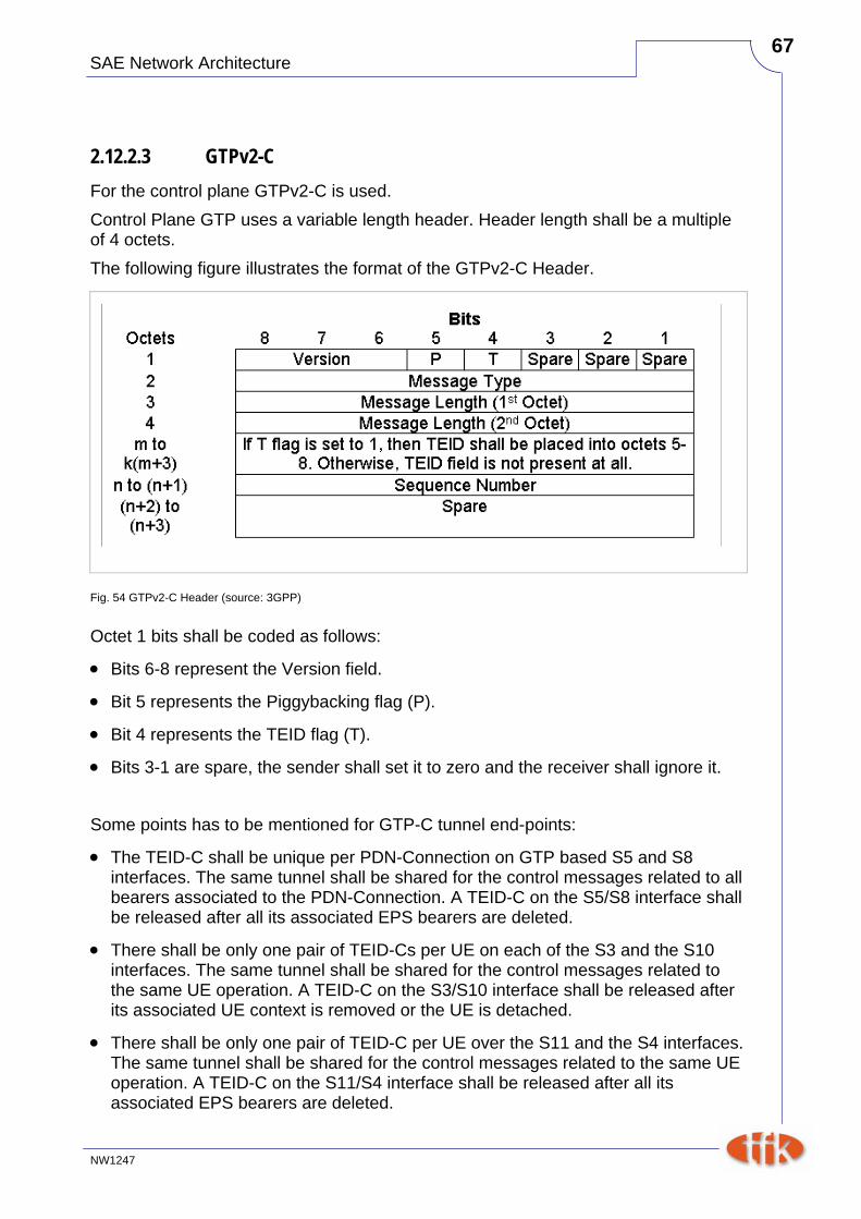
2.12.2.3 GTPv2-C For the control plane GTPv2-C is used. Control Plane GTP uses a variable length header. Header length shall be a multiple of 4 octets. The following figure illustrates the format of the GTPv2-C Header.
Fig. 54 GTPv2-C Header (source: 3GPP)
Octet 1 bits shall be coded as follows:
• Bits 6-8 represent the Version field.
• Bit 5 represents the Piggybacking flag (P).
• Bit 4 represents the TEID flag (T).
• Bits 3-1 are spare, the sender shall set it to zero and the receiver shall ignore it. Some points has to be mentioned for GTP-C tunnel end-points:
• The TEID-C shall be unique per PDN-Connection on GTP based S5 and S8 interfaces. The same tunnel shall be shared for the control messages related to all bearers associated to the PDN-Connection. A TEID-C on the S5/S8 interface shall be released after all its associated EPS bearers are deleted.
• There shall be only one pair of TEID-Cs per UE on each of the S3 and the S10 interfaces. The same tunnel shall be shared for the control messages related to the same UE operation. A TEID-C on the S3/S10 interface shall be released after its associated UE context is removed or the UE is detached.
• There shall be only one pair of TEID-C per UE over the S11 and the S4 interfaces. The same tunnel shall be shared for the control messages related to the same UE operation. A TEID-C on the S11/S4 interface shall be released after all its associated EPS bearers are deleted.
SAE Network Architecture
NW1247
68
Fig. 55 GTPv2 Message Types (source: 3GPP)
SAE Network Architecture
NW1247
69
SAE Network Architecture
NW1247
70
3 Architecture models
SAE Network Architecture
NW1247
71
3.1 Non-roaming architecture
3.1.1 Normal option The normal option uses two separate gateways: the Serving-GW and the PDN-GW.
Fig. 56 Non-roaming architecture for 3GPP accesses (source: 3GPP)
3.1.2 Single gateway option The single gateway option uses one single physical gateways for the Serving-GW and the PDN-GW.
Fig. 57 Non-roaming architecture for 3GPP accesses. Single gateway configuration option (source: 3GPP)
SAE Network Architecture
NW1247
72
3.2 Roaming architecture
3.2.1 Home routed scenario In this scenario the data path from the visited network is routed to the home PDN network. For this scenario the S8 interface between S-GW and PDN-GW is used.
Source: 3GPP
Fig. 58 Roaming architecture for 3GPP accesses. Home routed traffic
The following two figures represent the roaming with local breakout case with Application Function (AF) in the Home Network and in the Visited Network respectively. The concurrent use of AF's in the home network and AF's in the visited network is not excluded.
SAE Network Architecture
NW1247
73
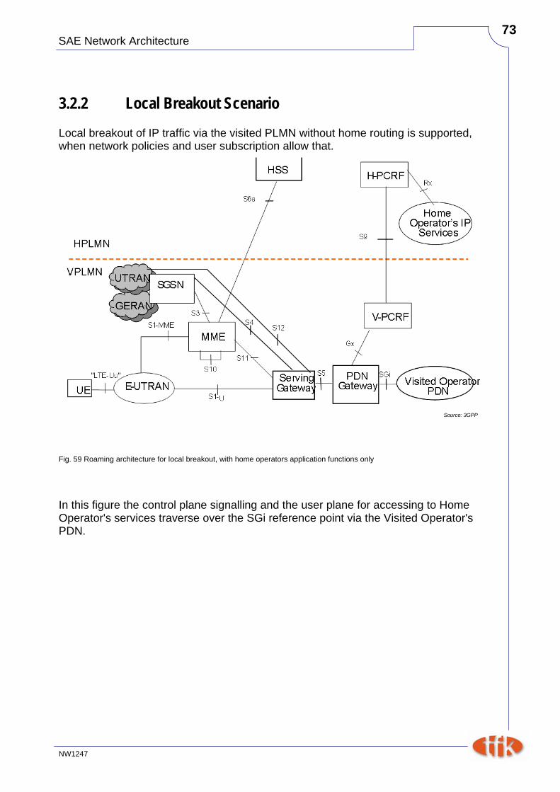
3.2.2 Local Breakout Scenario Local breakout of IP traffic via the visited PLMN without home routing is supported, when network policies and user subscription allow that.
Source: 3GPP
Fig. 59 Roaming architecture for local breakout, with home operators application functions only
In this figure the control plane signalling and the user plane for accessing to Home Operator's services traverse over the SGi reference point via the Visited Operator's PDN.
SAE Network Architecture
NW1247
74
Source: 3GPP
Fig. 60 Roaming architecture for local breakout, with visited operator's application functions only
SAE Network Architecture
NW1247
75
3.3 Non-3GPP Access Trusted and Untrusted Non-3GPP Access Networks are IP access networks that use access technologies like WiFi, WiMAX or any other kind of access technologies.
Trusted or Untrusted Non-3GPP Access Whether a Non-3GPP IP access network is Trusted or Untrusted is not a characteristic of the access network. In non-roaming scenario it is the HPLMN's operator decision if a Non-3GPP IP access network is used as Trusted or Untrusted Non-3GPP Access Network. In roaming scenario, the HSS/3GPP AAA Server in HPLMN makes the final decision of whether a Non-3GPP IP access network is used as Trusted or Untrusted non-3GPP Access Network. The HSS/3GPP AAA Server may take the VPLMN's policy and capability returned from the 3GPP AAA Proxy or roaming agreement into account. Trusted Non-3GPP access describes the situation that the Non-3GPP network (e.g. a WLAN access network) is controlled by the operator itself or by another entity (local operator or service provider) which can be trusted due to the existence of mutual agreements. The next figure gives an overview of all current interfaces which are necessary to integrate all (trusted and untrusted) Non-3GPP access networks. Some network nodes and interfaces are influenced by this access techniques, others aren´t. On the terminal side, no changes are required except some slight software adaptations. The main component to provide the interworking with Non-3GPP access networks is the 3GPP AAA Server. This server needs access to the HSS (provided by SWx interface) to retrieve user related subscriber information. The STa Interface has been defined for trusted access networks, whereas untrusted networks use the SWa Interface. MME is not needed here, because terminal location management is purely under control of the Non-3GPP access network. For untrusted access the ePDG (evolved Packet Data Gateway) is defined. This network element concentrates all traffic issued by or targeted to the access network. The main task is to establish a secure tunnel for user data transmission with the terminal using e.g. GRE and filter unauthorized traffic. The SWm Interface is used for exchanging user-related information between 3GPP AAA Server and ePDG. SWu interface allows terminals to setup a secure tunnel to the ePDG.
SAE Network Architecture
NW1247
76
)
Source: 3GPP
Fig. 61 Non-Roaming Architecture within EPS for Non-3GPP access using S5, S2a, S2b Interfaces