SpectraSensors’ SS2100 products are high-speed, diode-laser based extractive analyzers designed for extremely reliable monitoring of very low (trace) to standard concentrations of specific components in various background gases.
In order to operate the analyzer safely, it is important to closely review all information contained in this manual. This manual is divided into the following sections:
• General Safety Instructions
• Equipment Installation
• Equipment Operation
• Equipment Maintenance and Service
How to Use This ManualTake a moment to familiarize yourself with the content in this manual by reading the Table of Contents. This manual has been written to address the most common safety issues related to the installation and operation of the SS2100 analyzer. Additional information has been provided with the analyzer model purchased to instruct qualified users in the installation, operation and maintenance of the equipment.
Images, tables and charts have been included with instruction to provide a visual understanding of the analyzers and its functions. Special symbols are also used to provide the user with key information regarding the system configuration and/or operation. Users should pay close attention to this information.
Conventions used in this manual
In addition to the symbols and instructional information, this manual is created with “hot links” to enable the user to quickly navigate between different sections within the manual. These links include table, figure and section references and are identified by a pointing finger cursor when rolling over the text. Simply click on the link to navigate to the associated reference.
Documents Provided with the SS2100 AnalyzerEach SS2100 analyzer shipped from the factory is packaged with documents specific to the model that was purchased. At a minimum, the documents included with each shipment are:
• Safety Manual (electronic copy)
• Hardware Manual (electronic copy)
• Firmware Manual (electronic copy)
• System Drawings (paper copy)
• Calibration Certificate (paper copy)
Safety Manual 1–1
SS2100 Analyzer
SpectraSensors OverviewSpectraSensors, Inc. is a leading manufacturer of advanced optical gas analyzers. Headquartered in Houston, Texas, SpectraSensors was incorporated in 1999 as a spin-off of the NASA/Caltech Jet Propulsion Laboratory (JPL) for the purpose of commercializing space-proven measurement technologies initially developed at JPL. SpectraSensors was acquired by the Endress+Hauser Group in 2012.
Manufacturer AddressSpectraSensors, Inc.An Endress+Hauser Company11027 Arrow RouteRancho Cucamonga, CA 91730 United Stateswww.spectrasensors.com
1–2 4900002253 rev. C 9-30-20
2 - GENERAL SAFETY INFORMATION
This chapter reviews the general safety instructions for every SS2100 analyzer.
Intended Equipment UseThe SS2100 analyzer is intended for use as instructed in the documentation package provided with the equipment. SpectraSensors recommends that the qualified technician read and reference the documentation when installing, operating or having direct contact with the SS2100 analyzer. Any use of the equipment in a manner not specified by SpectraSensors could impair the protection provided by the equipment.
Warning LabelsEquipment labels are adhered to the SS2100 analyzer to alert the user of potential hazards. Instructional symbols are also used in the equipment manuals to indicate potential hazards, important information and valuable tips, and may not labeled on the analyzer. Following are the equipment labels and instructional symbols with associated warning and caution types to observe when operating the analyzer.
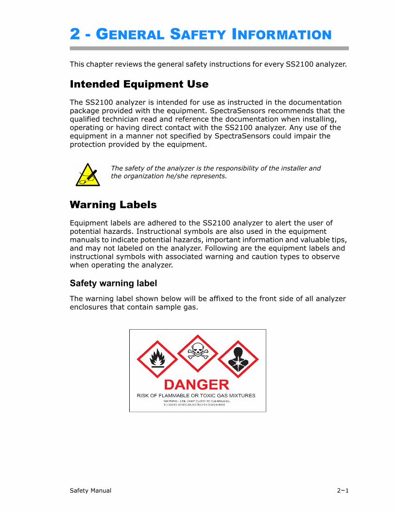
Safety warning label
The warning label shown below will be affixed to the front side of all analyzer enclosures that contain sample gas.
The safety of the analyzer is the responsibility of the installer and the organization he/she represents.
Safety Manual 2–1
SS2100 Analyzer
Hazards may vary by stream composition. One or more of the following conditions may apply.
Equipment labels
Flammable. Gases used in the processing of this analyzer may be extremely flammable. Any work in a hazardous area must be carefully controlled to avoid creating any possible ignition sources (e.g., heat, arcing, sparking, etc.).
Toxins. SpectraSensors analyzers measure a variety of gases, including high-level H2S. Follow all safety protocols governing toxic gases and potential leaks.
Inhalation. Inhaling toxic gases or fumes may cause physical damage or death.
Technicians are expected to follow all safety protocols established by the customer that are necessary for servicing or operating the analyzer. This may include, but is not limited to, lockout/tag-out procedures, toxic gas monitoring protocols, PPE requirements, hot work permits and other precautions that address safety concerns related to performing service or operation on process equipment located in hazardous areas.
Warning statement for hazardous voltage. Contact may cause electric shock or burn. Turn off and lock out system before servicing.
Failure to follow all directions may result in damage or malfunction of the analyzer.
Maximum voltage and current specifications for the fuse closest to label.
PROTECTIVE EARTH GROUND - Symbol indicates the connection point of the ground wire from the main power source.
2–2 4900002253 rev. C 9-30-20
General Safety Information
Instructional symbols
FUNCTIONAL EARTH GROUND - Symbol indicates grounding points intended primarily for troubleshooting.
INVISIBLE LASER RADIATION - Avoid exposure to beam. Class 3b Radiation Product. Refer servicing to the manufacturer or qualified personnel.
Removing label from measurement cell optical head will void analyzer warranty.
General notes and important information concerning the installation and operation of the analyzer.
Failure to follow all directions may result in fire.
INVISIBLE LASER RADIATION - Avoid exposure to beam. Class 3b Radiation Product. Refer servicing to the manufacturer-qualified personnel.
Failure to follow all directions may result in damage or malfunction of the analyzer.
Maximum voltage and current specifications for fuses.
CAUTIONCLASS 3B INVISIBLE LASER
RADIATION WHEN OPENAVOID EXPOSURE TO THE BEAM
Safety Manual 2–3
SS2100 Analyzer
Analyzer Technical SpecificationsRefer to Equipment ratings for specifications related to the SS2100 analyzer.
Peripheral devices
For systems equipped with peripheral devices, e.g., probe assemblies, refer to documentation provided by the manufacturer for instruction on installation, operation, etc.
Equipment ratings
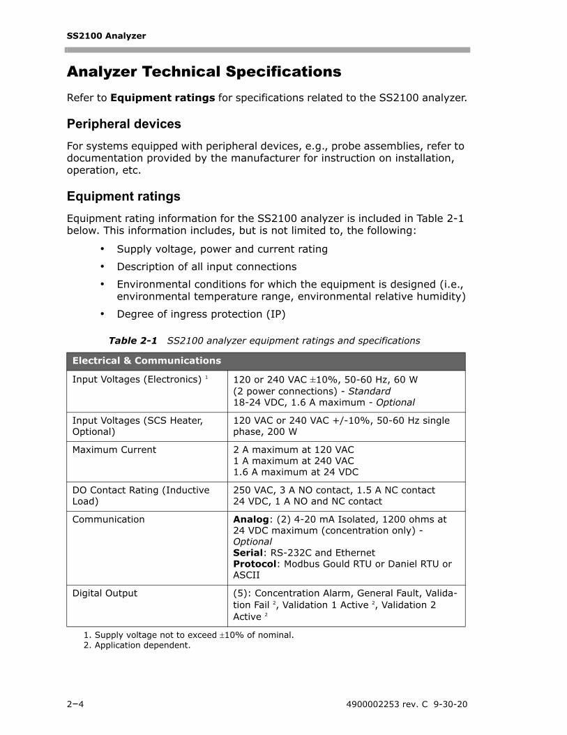
Equipment rating information for the SS2100 analyzer is included in Table 2-1 below. This information includes, but is not limited to, the following:
• Supply voltage, power and current rating
• Description of all input connections
• Environmental conditions for which the equipment is designed (i.e., environmental temperature range, environmental relative humidity)
• Degree of ingress protection (IP)
Table 2-1 SS2100 analyzer equipment ratings and specifications
Electrical & Communications
Input Voltages (Electronics) 1
1. Supply voltage not to exceed 10% of nominal.2. Application dependent.
120 or 240 VAC ±10%, 50-60 Hz, 60 W (2 power connections) - Standard18-24 VDC, 1.6 A maximum - Optional
Input Voltages (SCS Heater, Optional)
120 VAC or 240 VAC +/-10%, 50-60 Hz single phase, 200 W
Maximum Current 2 A maximum at 120 VAC1 A maximum at 240 VAC1.6 A maximum at 24 VDC
DO Contact Rating (Inductive Load)
250 VAC, 3 A NO contact, 1.5 A NC contact24 VDC, 1 A NO and NC contact
Communication Analog: (2) 4-20 mA Isolated, 1200 ohms at 24 VDC maximum (concentration only) - OptionalSerial: RS-232C and EthernetProtocol: Modbus Gould RTU or Daniel RTU or ASCII
Digital Output (5): Concentration Alarm, General Fault, Valida-tion Fail 2, Validation 1 Active 2, Validation 2 Active 2
2–4 4900002253 rev. C 9-30-20
General Safety Information
Potential Risks Affecting Personnel
This section addresses the appropriate actions to undertake before or during service of the analyzer when faced with hazardous situations such as exposure to process gases, electrocution, explosion or fire. It is not possible to list all
Table 2-1 SS2100 analyzer equipment ratings and specifications (Continued)
Application Data
Environmental Temperature Range/Sample Cell Temperature Range
–20 C to 50 C (–4 F to 122 F)–10 C to 60 C (14 F to 140 F) - Optional
Environmental Relative Humidity
5% to 95%, Non-condensing
Heated SCS Enclosure Temperature
50 C (122 F)60C (140 F) - Optional
Altitude Up to 2,000 m
Sample Inlet Pressure 130-340 kPaG (20-50 PSIG) to panel
Size (typical) 2 1300-1500 mm H 600-920 mm W 300-450 mm D (50-60” H 24-36” W 12-17” D)
Weight (typical) 2 Approximately 59 Kg (130 lbs) with Sample System
Area Classification
Analyzer with Sample Conditioning System (SCS)
Class I, Div.2 Grp. A, B, C, D T3 / T3CClass I, Zone 2 IIC T3 / T3CType 4X, IP66
2. Application dependent.
Technicians are expected to follow all safety protocols established by the customer that are necessary for servicing the analyzer. This may include, but is not limited to, lockout/tagout procedures, toxic gas monitoring protocols, PPE requirements, hot work permits and other precautions that address safety concerns related to performing service on process equipment located in hazardous areas.
Safety Manual 2–5
SS2100 Analyzer
potential hazards within this document. The user is responsible for identifying and mitigating any potential hazards present when servicing the analyzer.
Personnel Responsibility
Mitigating risks
Refer to the instructions for each situation listed below to mitigate associated risks.
Exposure to toxic gas (H2S)
Follow the procedure below if there has been any suspected leak from the sample system and accumulated SCS enclosure.
1. Purge the SCS enclosure to remove any potentially toxic gas.
2. Test the H2S levels of the SCS enclosure using the port from the safety purge kit to ensure the purge has cleared any toxic gas.
3. If no gas leak is detected, open the SCS enclosure door.
Electrocution hazard
1. Shut off power at the main disconnect external to the analyzer.
2. Open enclosure door.
If service must be performed with power engaged:
1. Note any live electrical components and avoid all contact with them.
2. Only use tools with a safety rating for protection against accidental contact with voltage up to 1000V (IEC 900, ASTF-F1505-04, VDE 0682/201).
The safety of the analyzer is the responsibility of the installer and the organization he/she represents.
Follow all safety protocols governing toxic gases and potential leaks.
Complete this action before performing any service that requires working near the main input power or disconnecting any wiring or other electrical components.
2–6 4900002253 rev. C 9-30-20
General Safety Information
Explosion/fire hazard
Any work in a hazardous area must be carefully controlled to avoid creating any possible ignition sources (e.g., heat, arcing, sparking, etc.). All tools must be appropriate for the area and hazards present. Electrical connections must not be made or broken with power on (to avoid arcing).
Safety Manual 2–7
SS2100 Analyzer
THIS PAGE INTENTIONALLY LEFT BLANK.
2–8 4900002253 rev. C 9-30-20
3 - EQUIPMENT INSTALLATION
The information in this chapter is related to safety during the equipment installation.
Mounting the AnalyzerThe SS2100 is manufactured for wall or Unistrut® (or equivalent) metal framing installations. Refer to the drawings provided in the hardware manual for detailed mounting dimensions of the purchased SS2100 analyzer model.
Lifting/carrying the analyzer
Due to the analyzer’s size and weight (59 Kg./130 lbs.), SpectraSensors recommends the use of a forklift, pallet jack, etc. to lift and/or move the analyzer. If the analyzer is to be lifted by hand, designate multiple individuals and distribute the weight among personnel to avoid injury.
Before removing from the crate, move the analyzer as close as possible to the final installation location. Never lift the analyzer by the electronics enclosure or
SpectraSensors Class 1 Division II analyzers use a non-incendive protection method, and as such all portions of the local installation codes apply. The maximum allowed inductance to resistance ratio (L/R ratio) for the field wiring interface must be less than 25 µH/Ω. The maximum total loop capacitance shall be 0.27 microfarads.
The safety of the analyzer is the responsibility of the installer and the organization he/she represents.
Configurations requiring optional accessories, e.g., probe assemblies, with specific characteristics must meet manufacturer specifications.
SpectraSensors analyzers are designed for operation within the specified ambient temperature range. Intense sun exposure in some areas may cause the analyzer temperature to exceed the maximum.
When mounting the analyzer, be sure to position the instrument so that it is not difficult to operate adjacent devices. Allow three feet (1 meter) of room in front of the analyzer.
Safety Manual 3–1
SS2100 Analyzer
conduit runs. Always carry the load using one of the following points/methods (refer to the drawings included with the purchased SS2100 analyzer model):
• Mounting points on Unistrut frame
• Cross members on Unistrut frame
• Support beneath instrument (best used when employing a forklift)
Electrical Wiring Requirements
External circuit breaker requirements
Ensure all equipment used for lifting/moving the analyzer is rated for the weight load.
Bolts or screws used for wall-mounting the SS2100 must be able to support four times the weight of the instrument (59 Kg./130 lbs.).
Interconnection of the analyzer enclosure and cell enclosure shall be performed using wiring methods approved for Class I, Division 2 or Zone 2 hazardous locations per the Canadian Electrical Code (CEC) Appendix B or J and the National Electric Code (NEC) Article 501 or 505. The installer is responsible for complying with all local installation codes.
Use copper conductors only.
An approved switch or circuit breaker rated for 15 amps should be used and clearly marked as the disconnecting device for the analyzer.
If the breaker in the customer-provided power distribution panel or switch is the primary means of disconnecting the power from the analyzer, SpectraSensors recommends that the power distribution panel be located in close proximity to the equipment and within easy reach of the operator.
3–2 4900002253 rev. C 9-30-20
Equipment Installation
Protective Chassis and Ground Connections
Before connecting any electrical signal or power, the protective and chassis grounds must be connected. Requirements for the protective and chassis grounds include the following:
• Protective and chassis grounds must be of equal or greater size than any other current-carrying conductors, including the heater located in the sample conditioning system
• Protective and chassis grounds to remain connected until all other wiring is removed
• Insulated protective and chassis ground wiring must use the green/yellow color
• Protective grounding wire current carrying capacity must be at minimum the same as the main supply
• Earth bonding/chassis ground shall be at least 12 AWG (4 mm2)
Color coding
Green-and-yellow insulation shall only be used for:
• Protective earth conductors
• protective bonding conductors
• potential equalization conductors for safety purposes
• functional earth
Connections to the SupplyUse the following procedure to connect the sample supply line.Consult the layout and flow diagrams in the system drawings. All work must be performed by technicians qualified in pneumatic tubing.
A switch or circuit breaker must not interrupt a protective earth conductor.
Thread lubricant must be applied on all conduit hub threaded connections. SpectraSensors recommends using STL8 lubricant on all conduit screw thread and it’s taped openings.
Safety Manual 3–3
SS2100 Analyzer
SpectraSensors recommends using 1/4” O.D x 0.035” wall thickness, seamless stainless steel tubing. Refer to the system layout drawings for supply and return port locations.
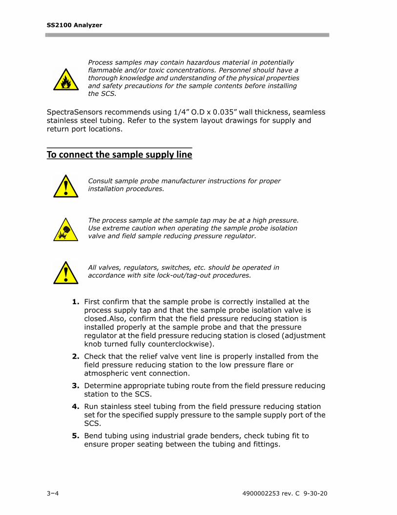
To connect the sample supply line
1. First confirm that the sample probe is correctly installed at the process supply tap and that the sample probe isolation valve is closed.Also, confirm that the field pressure reducing station is installed properly at the sample probe and that the pressure regulator at the field pressure reducing station is closed (adjustment knob turned fully counterclockwise).
2. Check that the relief valve vent line is properly installed from the field pressure reducing station to the low pressure flare or atmospheric vent connection.
3. Determine appropriate tubing route from the field pressure reducing station to the SCS.
4. Run stainless steel tubing from the field pressure reducing station set for the specified supply pressure to the sample supply port of the SCS.
5. Bend tubing using industrial grade benders, check tubing fit to ensure proper seating between the tubing and fittings.
Process samples may contain hazardous material in potentially flammable and/or toxic concentrations. Personnel should have a thorough knowledge and understanding of the physical properties and safety precautions for the sample contents before installing the SCS.
Consult sample probe manufacturer instructions for proper installation procedures.
The process sample at the sample tap may be at a high pressure. Use extreme caution when operating the sample probe isolation valve and field sample reducing pressure regulator.
All valves, regulators, switches, etc. should be operated in accordance with site lock-out/tag-out procedures.
3–4 4900002253 rev. C 9-30-20
Equipment Installation
6. Fully ream all tubing ends. Blow out the line for 10 to 15 seconds with clean, dry nitrogen or air prior to making the connection.
7. Connect the sample supply tube to the SCS using the 1/4” stainless steel compression-type fitting provided.
8. Tighten all new fittings 1-1/4 turns with a wrench from finger tight. For connections with previously swaged ferrules, thread the nut to the previously pulled up position, then tighten slightly with a wrench. Secure tubing to appropriate structural supports as required.
9. Check all connections for gas leaks. SpectraSensors recommends using a liquid leak detector.
Ventilation RequirementsThere are no special requirements for ventilation of the analyzer. Refer to “Potential Risks Affecting Personnel” on page 2-5 for information related to mitigating risks associated with process gases, etc.
Do not exceed 10 PSIG (0.7 barg) in sample cell. Damage to cell may result.
Safety Manual 3–5
SS2100 Analyzer
THIS PAGE INTENTIONALLY LEFT BLANK.
3–6 4900002253 rev. C 9-30-20
4 - EQUIPMENT OPERATION
This chapter provides an overview of safety operational instructions for the SS2100 analyzer.
Firmware VersionEach SpectraSensors analyzer operates based on its own version of firmware. The firmware version for each analyzer is listed in the system calibration report, and displays upon start-up of the analyzer. Detailed operational instructions are provided in the firmware manual shipped with the purchased analyzer. Manuals can also be found on the SpectraSensors website (www.spectrasensors.com) by model type.
Operating ControlsThe front panel mounted keypad enables the operator to modify measurement units, adjust operational parameters, and perform diagnostics. These instructions are found in the appropriate firmware manual.
During normal operation, the LCD continuously displays the measured component’s concentration, sample cell temperature, and sample cell pressure.
The SpectraSensors keypads for CSA and ATEX certified products are shown in Figure 4–1 and Figure 4–2 on page 4–2. CSA-certified products include the SS2100, 2-Pack, 3-Pack, SS500/SS2000/SS300, SS500e/SS2000e/SS3000e, SS500XP/SS2000XP. ATEX-certified products include the SS2100a, SS2100i-1 and SS2100i-2.
To activate any functions on the keypad, press the mode key # followed by a number on the keypad to specify a mode.
When you press the # key, the words <MODE MENU> display on the LCD. If the keypad watchdog is enabled, a countdown timer will begin when <MODE MENU> displays. If the countdown expires and no buttons have been pressed, the analyzer will automatically revert to Mode 1.
The * key functions as the “Enter” key. When in Mode 2, always press * after entering a value using the keypad (unless the entry was made in error). Pressing the * key stores the displayed parameter value and cycles the LCD to the next parameter.
If you do make an error, press the * key followed by the TEST key, and then the * key to return to the parameter and enter the correct value.
You must press the # key before pressing a number or function key to trigger a response from the keypad.
Safety Manual 4–1
SS2100 Analyzer
A
#MODE
*ENTER E TEST
1 2 3
4 5 6
7 8 9
- 0 .
ENTER KEY
MODE MENUKEY
ACTIVATE PROCESSGAS
DIAGNOSTICSPARAMETERS
ACTIVATEVALIDATION 1
ANALOG OUTPUTTEST
LCD (DISPLAY)EXPONENT VALUE
SCROLL DIRECTION AND ANALOG INPUT TEST
SCRUBBER LIFE DATA
EXPORT DIAGNOSTIC DATA
VALIDATION RESULTS
ACTIVATE VALIDATION 2
CHANGE PARAMETERS
Figure 4–1 Keypad for CSA-certified analyzers
Figure 4–2 Keypad for ATEX-certified analyzers
*ENTER
E
TEST
1 2
9
- .
3
4 5 6
7 8
0
#MODE
ENTER KEY
MODE MENU KEY
EXPONENT VALUE
SCROLL DIRECTIONAND ANALOG INPUTTEST
ACTIVATEPROCESS GAS
DIAGNOSTICSPARAMETERS
ACTIVATEVALIDATION 1
ACTIVATEVALIDATION 2
CHANGEPARAMETERS
SCRUBBER LIFE DATA
EXPORT DIAGNOSTIC DATA
VALIDATION RESULTS
NALOG OUTPUTTEST
4–2 4900002253 rev. C 9-30-20
Equipment Operation
Intermittent Operation
To isolate the measurement cell for short‐term shutdown
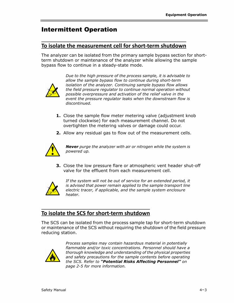
The analyzer can be isolated from the primary sample bypass section for short-term shutdown or maintenance of the analyzer while allowing the sample bypass flow to continue in a steady-state mode.
1. Close the sample flow meter metering valve (adjustment knob turned clockwise) for each measurement channel. Do not overtighten the metering valves or damage could occur.
2. Allow any residual gas to flow out of the measurement cells.
3. Close the low pressure flare or atmospheric vent header shut-off valve for the effluent from each measurement cell.
To isolate the SCS for short‐term shutdown
The SCS can be isolated from the process sample tap for short-term shutdown or maintenance of the SCS without requiring the shutdown of the field pressure reducing station.
Due to the high pressure of the process sample, it is advisable to allow the sample bypass flow to continue during short-term isolation of the analyzer. Continuing sample bypass flow allows the field pressure regulator to continue normal operation without possible overpressure and activation of the relief valve in the event the pressure regulator leaks when the downstream flow is discontinued.
Never purge the analyzer with air or nitrogen while the system is powered up.
If the system will not be out of service for an extended period, it is advised that power remain applied to the sample transport line electric tracer, if applicable, and the sample system enclosure heater.
Process samples may contain hazardous material in potentially flammable and/or toxic concentrations. Personnel should have a thorough knowledge and understanding of the physical properties and safety precautions for the sample contents before operating the SCS. Refer to “Potential Risks Affecting Personnel” on page 2-5 for more information.
Safety Manual 4–3
SS2100 Analyzer
1. Isolate the analyzer from the bypass following the procedure under “To isolate the measurement cell for short-term shutdown” on page 4-3.
2. Close the sample supply shut-off valve to the SCS.
3. Allow the sample bypass to flow until all residual gas has dissipated from the lines as indicated by no flow on the sample bypass flow meter.
4. Close the low pressure flare or atmospheric vent header shut-off valve for the effluent from the sample bypass.
5. Turn off power to the analyzer.
Although the pressure reducing regulator at the process sample tap is designed for “bubble-tight” shut off, this condition may not occur after the system has been in operation for an extended period. Isolation of the SCS from the field pressure regulator will discontinue sample flow and may cause the pressure at the outlet of the field pressure regulator to slowly increase if “bubble-tight” shut off of the pressure regulator does not occur. The slow pressure increase will continue until the pressure setpoint of the relief valve is reached and the excess pressure is vented by the relief valve. Although this situation is not intended, it does not cause a significant problem if the SCS is only isolated for a short period. Only a small amount of process sample will be vented when the relief valve opens because the pressure regulator will continue to act as a flow restriction.
If the system will not be out of service for an extended period, it is advised that power remain applied to the sample transport line electric tracer, if applicable, and the sample system enclosure heater.
4–4 4900002253 rev. C 9-30-20
5 - MAINTENANCE AND SERVICE
This chapter provides safety information for the maintenance and service of the SS2100 analyzer.
Potentially Hazardous SubstancesSS2100 analyzers that detect H2S can acquire leaks that lead to unsafe amounts of toxic gas. Refer to “Mitigating risks” on page 2-6.
Disposal of hazardous substances
For analyzers equipped with H2S scrubbers, discard used scrubber and scrubber indicator in an appropriate leak-proof receptacle. Refer to “Disposal of Used Scrubbers” on page 5-8.
Instructions for Cleaning and Decontamination
To keep the sampling lines clean
1. Make sure that a membrane separator filter (included with most systems) is installed ahead of the analyzer and operating normally. Replace the membrane if necessary. If liquid enters the cell and accumulates on the internal optics, a Laser Power too Low fault message at the display will result.
2. Turn off the sample valve at the tap in accordance with site lock-out, tag-out rules.
3. Disconnect the gas sampling line from the sample supply port of the analyzer.
4. Wash the sampling line with isopropyl alcohol or acetone and blow dry with mild pressure from a dry air or nitrogen source.
5. Once the sampling line is completely free of solvent, reconnect the gas sampling line to the sample supply port of the analyzer.
6. Check all connections for gas leaks. SpectraSensors recommends using a liquid leak detector.
Depleted H2S scrubbers and scrubber indicators contain predominantly Copper (II) Sulfide [CAS# 1317-40-4] with. some remaining Copper (II) Oxide [CAS# 1317-38-0] and basic cupric carbonate [CAS# 12069-69-1], each of which are odorless dark powders that require few special precautions other than avoiding contact with the internal substances, keeping the scrubber tightly sealed and protecting the contents against humidity.
Safety Manual 5–1
SS2100 Analyzer
To prevent electrostatic discharge
1. Use a damp cloth to clean the displays to avoid static electricity discharge.
Replacement PartsAll parts required for operation of the SS2100 analyzer must be supplied by SpectraSensors or an authorized agent. Refer to Service Contact for contact information to determine specific parts listing for the purchased model.
Fuse Ratings and Characteristics
If you need to replace a fuse, use only the same type and rating of fuse as the original. Refer also to specifications listed in Table 5-1 below.
Select the replacement solenoid fuse (F2) based on the number of solenoids installed on the analyzer.
Table 5-1 Fuse specifications
Drawing Reference Voltage Description Rating
Figure 5–1
F1 120 VAC
1 Solenoid, Miniature Fuse, 5 x 20 mm, Time Delay
250 VAC 0.125 A
2 Solenoids, Miniature Fuse, 5 x 20 mm, Time Delay
250 VAC 0.25 A
3 Solenoids, Miniature Fuse, 5 x 20 mm, Time Delay
250 VAC 0.4 A
F2 120 VAC
Miniature Fuse, 5 x 20 mm, Time Delay
250 VAC 0.8 A
F1 240 VAC
1 Solenoid, Miniature Fuse, 5 x 20 mm, Time Delay
250 VAC 0.63 A
2 Solenoids, Miniature Fuse, 5 x 20 mm, Time Delay
250 VAC 1.25 A
3 Solenoids, Miniature Fuse, 5 x 20 mm, Time Delay
250 VAC 2.0 A
F2 240 VAC
Miniature Fuse, 5 x 20 mm, Time Delay
250 VAC 1.6 A
5–2 4900002253 rev. C 9-30-20
Maintenance and Service
.
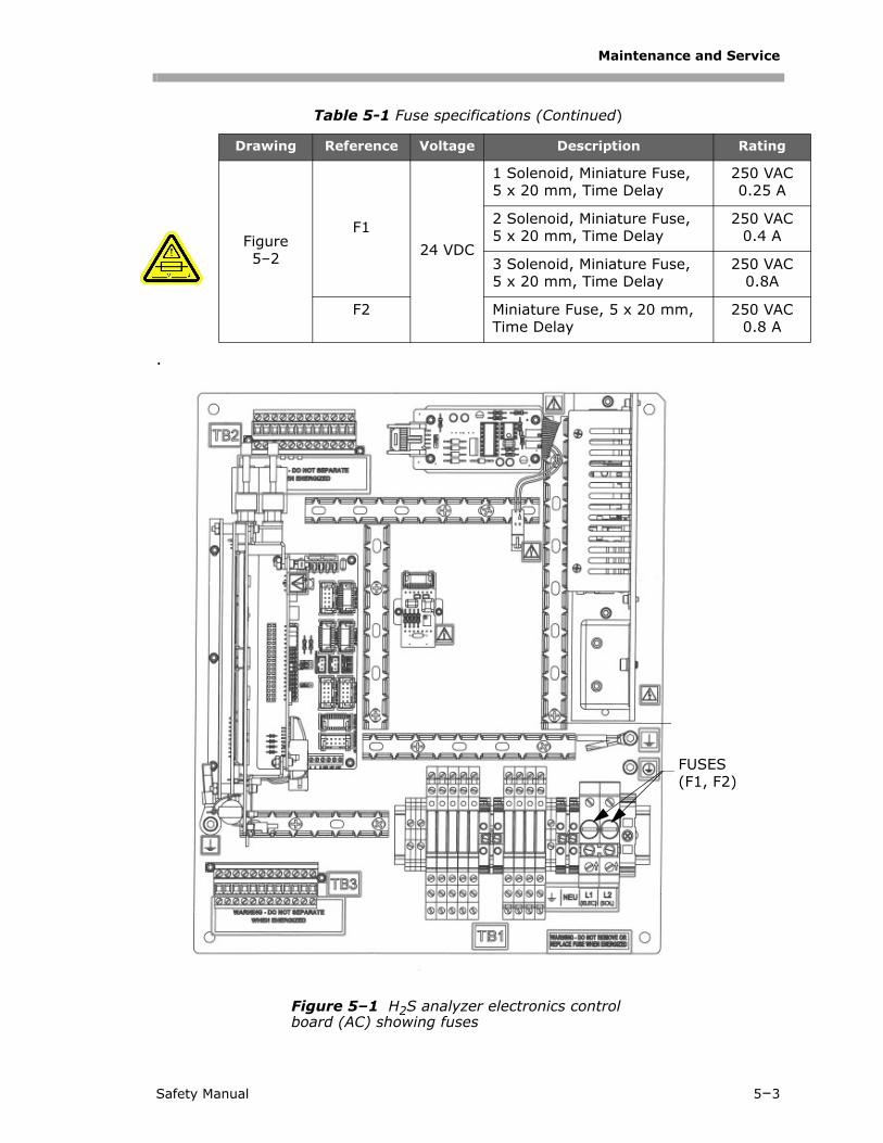
Table 5-1 Fuse specifications (Continued)
Drawing Reference Voltage Description Rating
Figure 5–2
F124 VDC
1 Solenoid, Miniature Fuse, 5 x 20 mm, Time Delay
250 VAC0.25 A
2 Solenoid, Miniature Fuse, 5 x 20 mm, Time Delay
250 VAC0.4 A
3 Solenoid, Miniature Fuse, 5 x 20 mm, Time Delay
250 VAC0.8A
F2 Miniature Fuse, 5 x 20 mm, Time Delay
250 VAC0.8 A
Figure 5–1 H2S analyzer electronics control board (AC) showing fuses
FUSES (F1, F2)
Safety Manual 5–3
SS2100 Analyzer
Replacing a Fuse
1. Power off the system and close the sample supply valve.
2. Open the electronics enclosure. Refer to Figure 5–1 (AC) or Figure 5–2 (DC) for fuse location
3. Using a flat-head screwdriver, remove the fuse screw turning counterclockwise as shown in Figure 5–3 on page 5–5.
4. Remove the fuse cover and fuse.
5. Remove the fuse from the cover and replace with a new fuse as shown in Figure 5–4 on page 5–5. Refer to Table 5-1 on page 5–2 for fuse specifications.
Figure 5–2 H2S analyzer electronics control board (DC) showing fuses
FUSE (F1)
FUSE (F2)
5–4 4900002253 rev. C 9-30-20
Maintenance and Service
6. Insert the new fuse into the screw cover and replace into the fuse opening.
7. Use the screwdriver to turn the fuse cover clockwise until tight. Do not overtighten.
8. Close enclosure door and apply power to the analyzer.
Repeat steps for each fuse to be replaced.
Figure 5–3 Unscrewing fuse cover
FUSE COVER
Figure 5–4 Replacing fuse
FUSE
Safety Manual 5–5
SS2100 Analyzer
Replacing the Membrane Separator
Use the following steps to replace a membrane separator.
1. Close the sample supply valve.
2. Unscrew the cap from the membrane separator.
If the membrane filter is dry:
3. Check if there are any contaminants or discoloring of the white membrane. If yes, the filter should be replaced.
4. Remove the O-ring and replace the membrane filter.
5. Replace the O-ring on top of the membrane filter.
6. Place the cap back onto the membrane separator and tighten.
7. Check upstream of the membrane for liquid contamination and clean and dry out before re-opening the sample supply valve.
If liquid or contaminants are detected on the filter:
3. Drain any liquids and clean with isopropyl alcohol.
4. Clean any liquids or contaminants from the base of the membrane separator.
5. Replace the filter and the O-ring.
6. Place the cap onto the membrane separator and tighten.
7. Check upstream of the membrane for liquid contamination and clean and dry out before re-opening the sample supply valve.
8. Check connections for gas leaks. SpectraSensors recommends using a liquid leak detector.
Replacing the Filter
If necessary, use the following steps to replace the filter:
1. Close the sample supply valve.
2. Unscrew the four screws with a 5/23” screwdriver from the base of the filter. Remove the filter unit from the analyzer for disassembly.
3. Unscrew and remove the filter cap.
4. Remove the top O-ring.
5. Check if there are any contaminants or solid components blocking the metal filter.
6. Drain any contaminants found and clean with isopropyl alcohol.
7. Replace the top O-ring.
8. Place the filter cap back into position and tighten.
5–6 4900002253 rev. C 9-30-20
Maintenance and Service
9. Place the filter unit into the analyzer and tighten the base with the four screws.
10. Check upstream of membrane for liquid contamination and clean and dry out before opening the sample supply valve.
11. Check connections for gas leaks. SpectraSensors recommends using a liquid leak detector.
Replacing the scrubber and scrubber efficiency indicator
1. Close the sample supply shut-off valve. Allow all residual gas to dissipate as indicated by no flow on the sample bypass flow meter.
2. Unscrew the compression nuts on the inlet end of the scrubber and scrubber efficiency indicator assembly.
3. To install the new scrubber and indicator, insert the inlet and outlet tubes into the compression fittings of a new scrubber and scrubber efficiency indicator assembly, ensuring each are oriented correctly, as shown in Figure 5–5 below.
All valves, regulators, switches, etc. should be operated in accordance with site lock-out/tag-out procedures.
Figure 5–5 Scrubber and scrubber efficiency indicator
Safety Manual 5–7
SS2100 Analyzer
4. Tighten all new fittings 1-1/4 turns with a wrench from finger tight. For connections with previously swaged ferrules, thread the nut to the previously pulled up position, then tighten slightly with a wrench.
5. Reset the scrubber lifetime monitor with the New Scrub Installed parameter and the General Fault Alarm with the Reset option for the General Alarm DO parameter (see “To change parameters in Mode 2” in the Firmware Manual for your analyzer).
6. Restart the SCS.
7. Check all connections for gas leaks. SpectraSensors recommends using a liquid leak detector.
8. Re-validate the system with an appropriate gas standard following the instructions under “Validating the Analyzer” in the Firmware Manual for your analyzer.
9. Purge the scrubber and scrubber efficiency indicator assembly with nitrogen to remove all flammable gas and cap the inlet and outlet.
Disposal of Used Scrubbers
1. Discard used scrubber and scrubber indicator in an appropriate leak-proof receptacle.
Service ContactFor Technical Service, refer to our website for the list of local sales channels in your area (https://www.spectrasensors.com/contact).
H2S scrubbers and scrubber indicators contain Copper (II) Oxide [CAS# 1317-38-0] and basic cupric carbonate [CAS# 12069-69-1], which are harmful if swallowed and toxic to aquatic organisms. Handle with care and avoid contact with the internal substances.
Depleted H2S scrubbers and scrubber indicators contain predominantly Copper (II) Sulfide [CAS# 1317-40-4] with some remaining Copper (II) Oxide [CAS# 1317-38-0] and basic cupric carbonate [CAS# 12069-69-1], each of which are odorless dark powders that require few special precautions other than avoiding contact with the internal substances, keeping the scrubber tightly sealed and protecting the contents against humidity.
If returning the unit is required, obtain a Service Repair Order (SRO) Number from Customer Service before returning the analyzer to the factory. Your service representative can determine whether the analyzer can be serviced on site or should be returned to the factory. All returns should be shipped to:
SpectraSensors, Inc.An Endress+Hauser Company11027 Arrow Rte.Rancho Cucamonga, CA 91730-4866United States of America1-909-948-4100