28
GB Safety & Operation Manual GA 60 Model 544913 4117232-Rev A

GB
Safety & OperationManual
GA 60
Model 544913
4117232-Rev A

Litho in U.S.A. 10-2002 2002 TEXTRON INC. • All Rights Reserved.Lincoln, Nebraska • Printed in U.S.A.
GENERAL INFORMATION
IMPORTANT!
THIS MANUAL WILL AID YOU IN THE SAFEOPERATION AND PROPER MAINTENANCE OFYOUR EQUIPMENT. READ MANUAL THOROUGHLYBEFORE ATTEMPTING OPERATION. IF ANYPORTION IS NOT CLEARLY UNDERSTOOD,CONTACT AN AUTHORIZED DEALER FORCLARIFICATION.
To make sure you are fully aware of safety and serviceinformation, the following two symbols are usedthroughout this manual.
!! This symbol is used throughout the manual toalert you to information about unsafe actions orsituations, and will be followed by the word DANGER,WARNING, or CAUTION. DANGER indicatesimmediate hazards that may result in severe injury ordeath. WARNING indicates unsafe actions or situationsthat may cause severe injury, death and/or majorequipment or property damage. CAUTION indicatesunsafe actions or situations that may cause injury, and/orminor equipment or property damage.
NOTE: This appears next to information or instructionswhich will help you operate and maintain yourequipment the right way.
WARNING!� The information and instructions included
in this manual alert you to certain thingsyou should do very carefully. If you do not,you could:
• hurt yourself or others • hurt the next person who operates the equipment• damage the equipment.
� This manual contains essential operationand safety information and must remainwith the unit at all times, within easy ac-cess of any operator.
Additional manuals are available through your dealer.
IMPORTANT!
THIS EQUIPMENT SHOULD NOT BE MODIFIED ORADDED TO WITHOUT THE MANUFACTURER’SAUTHORIZATION.
WARNING!� Altering this equipment in any manner
which adversely affects the equipmentsoperation, performance, durability or use,may cause hazardous conditions.
Direct any inquiries to:Textron Golf, Turf and Specialty ProductsAttn: Director of EngineeringP.O. Box 7708Charlotte, NC 28241–7708 USA
SPECIFICATION INFORMATION
All information contained in this manual is the latestavailable at the time of printing. Textron Golf, Turf andSpecialty Products reserves the right to make changesat any time without notice.
Whenever a name brand product is specified, anequivalent product may be used unless stated otherwise.
CHANGE OF OWNERSHIP OR ADDRESS
Textron Golf, Turf and Specialty Products makes everyeffort to keep owners informed of all safety relatedinformation. Therefore, changes in ownership and/oraddress should be reported to the manufacturer.
Your dealer has REGISTRATION CHANGE FORMSwhich will be filled out and filed by the dealer for hisrecords, and a copy will be sent to the manufacturer.
DEALER INFORMATION
For your nearest dealer location write to:Textron Golf, Turf and Specialty ProductsAttn: SalesP.O. Box 7708Charlotte, NC 28241–7708 USA
In the USA and Canada call 1–800–228–4444 (dealerinformation only).

1
TABLE OF CONTENTS1 Operation Safety 2. . . . . . . . . . . . . . . . . . . . . . . . . . . . . . . . . . . . . . . . . . . .
2 Decals 3-4. . . . . . . . . . . . . . . . . . . . . . . . . . . . . . . . . . . . . . . . . . . . . . . . . . .
3 Identification 5. . . . . . . . . . . . . . . . . . . . . . . . . . . . . . . . . . . . . . . . . . . . . . .
3.1 Model Number and Serial Number 5. . . . . . . . . . . . . . . . . . . . . . . . . . . . . . .
4 Service Parts and Support Material 5. . . . . . . . . . . . . . . . . . . . . . . . . .
5 Specifications 6. . . . . . . . . . . . . . . . . . . . . . . . . . . . . . . . . . . . . . . . . . . . . .
5.2 Towing Vehicle Specifications (Turf Trucksters) 6. . . . . . . . . . . . . . . . . . . . 5.3 Towing Vehicle Specifications (Turf Utility Tractor) 6. . . . . . . . . . . . . . . . .
6 Set Up 7. . . . . . . . . . . . . . . . . . . . . . . . . . . . . . . . . . . . . . . . . . . . . . . . . . . . .
6.1 Set Up Instruction for Turf Truckster 7. . . . . . . . . . . . . . . . . . . . . . . . . . . . . 6.2 Power Cable Installation 7. . . . . . . . . . . . . . . . . . . . . . . . . . . . . . . . . . . . . . . 6.3 Tongue Installation 8. . . . . . . . . . . . . . . . . . . . . . . . . . . . . . . . . . . . . . . . . . . . 6.4 Hitch Coupler Installation 9. . . . . . . . . . . . . . . . . . . . . . . . . . . . . . . . . . . . . . . 6.5 Reinstalling Side Panels 9. . . . . . . . . . . . . . . . . . . . . . . . . . . . . . . . . . . . . . . . 6.6 Set Up Instruction for Tractor 10. . . . . . . . . . . . . . . . . . . . . . . . . . . . . . . . . . 6.7 Removing From Pallet 11. . . . . . . . . . . . . . . . . . . . . . . . . . . . . . . . . . . . . . . . 6.8 Installing Tines 12. . . . . . . . . . . . . . . . . . . . . . . . . . . . . . . . . . . . . . . . . . . . . . .
7 Operation 13. . . . . . . . . . . . . . . . . . . . . . . . . . . . . . . . . . . . . . . . . . . . . . . . .
7.1 Pre–Operation Check 13. . . . . . . . . . . . . . . . . . . . . . . . . . . . . . . . . . . . . . . . . 7.2 Control Panel 13. . . . . . . . . . . . . . . . . . . . . . . . . . . . . . . . . . . . . . . . . . . . . . . . 7.3 Before Starting Engine 13. . . . . . . . . . . . . . . . . . . . . . . . . . . . . . . . . . . . . . . . 7.4 GA–60 Starting Procedure 14. . . . . . . . . . . . . . . . . . . . . . . . . . . . . . . . . . . . . 7.5 Beginning Aeration 14. . . . . . . . . . . . . . . . . . . . . . . . . . . . . . . . . . . . . . . . . . . 7.6 Aerating Depth Adjustment 15. . . . . . . . . . . . . . . . . . . . . . . . . . . . . . . . . . . .
8 Maintenance 13. . . . . . . . . . . . . . . . . . . . . . . . . . . . . . . . . . . . . . . . . . . . . . .
8.1 Daily Maintenance 17. . . . . . . . . . . . . . . . . . . . . . . . . . . . . . . . . . . . . . . . . . . . 8.2 Lubrication Fittings 17. . . . . . . . . . . . . . . . . . . . . . . . . . . . . . . . . . . . . . . . . . . 8.3 Air Cleaner 18. . . . . . . . . . . . . . . . . . . . . . . . . . . . . . . . . . . . . . . . . . . . . . . . . . 8.4 Checking Element 18. . . . . . . . . . . . . . . . . . . . . . . . . . . . . . . . . . . . . . . . . . . . 8.5 Installing Element 18. . . . . . . . . . . . . . . . . . . . . . . . . . . . . . . . . . . . . . . . . . . . 8.6 Fuel System 19. . . . . . . . . . . . . . . . . . . . . . . . . . . . . . . . . . . . . . . . . . . . . . . . . 8.7 Fuel Filter 19. . . . . . . . . . . . . . . . . . . . . . . . . . . . . . . . . . . . . . . . . . . . . . . . . . . 8.8 Engine Choke Control 19. . . . . . . . . . . . . . . . . . . . . . . . . . . . . . . . . . . . . . . . 8.9 Engine Oil 20. . . . . . . . . . . . . . . . . . . . . . . . . . . . . . . . . . . . . . . . . . . . . . . . . . . 8.10 Engine Oil Level 20. . . . . . . . . . . . . . . . . . . . . . . . . . . . . . . . . . . . . . . . . . . . . 8.11 Drive Chain Lubrication 20. . . . . . . . . . . . . . . . . . . . . . . . . . . . . . . . . . . . . . . 8.12 Towing 20. . . . . . . . . . . . . . . . . . . . . . . . . . . . . . . . . . . . . . . . . . . . . . . . . . . . . . 8.13 Tire Pressure 20. . . . . . . . . . . . . . . . . . . . . . . . . . . . . . . . . . . . . . . . . . . . . . . . 8.14 Daily Storage 20. . . . . . . . . . . . . . . . . . . . . . . . . . . . . . . . . . . . . . . . . . . . . . . .
9 Tine Holders 21. . . . . . . . . . . . . . . . . . . . . . . . . . . . . . . . . . . . . . . . . . . . . . .
10 Tines 22-23. . . . . . . . . . . . . . . . . . . . . . . . . . . . . . . . . . . . . . . . . . . . . . . . . . .
11 Torque Chart 24. . . . . . . . . . . . . . . . . . . . . . . . . . . . . . . . . . . . . . . . . . . . . .
12 Warranty 25–26. . . . . . . . . . . . . . . . . . . . . . . . . . . . . . . . . . . . . . . . . . . . . . .

1 OPERATION SAFETY
2
WARNING!EQUIPMENT OPERATED IMPROPERLY OR BY
UNTRAINED PERSONNEL CAN BE DANGEROUS
This is heavy equipment. Improper use, or operat-ing the unit in areas that may cause it to overturn,could cause serious injury or death to you the oper-ator or bystanders.
READ and understand the operator’s manual be-fore attempting to operate this unit.
Immediately replace any warning and/or safetydecal that becomes damaged or difficult to read.
This product is heavy equipment and may present acrush hazard unless safety precautions are taken.
DO NOT place hands or feet beneath unit at anytime, unless engine is shut off and yellow uplatchbar is securing unit in “UP” position.
Allow ONLY trained and authorized persons to op-erate this unit. NEVER allow children to operate thisunit. Local regulations may restrict the age of theoperator.
Use ONLY the standard drawbar approved by thetractor manufacturer. The height from the groundto the top of the drawbar must be 13 to 19.7 inches(330–500 mm).
Never operate the unit while under the influence ofalcohol or drugs.
Never operate the unit while people, especially chil-dren, or pets are nearby.
Keep in mind that the operator or user is responsi-ble for accidents or hazards occurring to otherpeople or property.
BEFORE using the unit, always inspect it for prob-lems. If something is wrong, DO NOT USE IT. Fix theproblem before using the unit to prevent possibleinjury.
WHILE using the unit, if something is found to bewrong, STOP using it. Fix the problem before theunit is used again.
Operate the machine up and down the slope (verti-cally), not across the face of the slope (horizon-tally).
ALWAYS use good judgement when operating onor near hills or slopes. NEVER start or stop sud-denly, you may cause unstable operating condi-tions. NEVER change directions abruptly or makesharp turns on slopes.
DO NOT place hands or feet near or under movingparts at any time.
Check work area and remove foreign objects whichmay be a hazard to the operator, bystanders ordamage the equipment.
To prevent damage to the unit or other equipment,BE SURE all under ground obstacles are clearlymarked.
Make sure all shields and guards are in place toprevent possible injury.
NEVER attempt to aerate in reverse.
Always run unit engine where there is plenty offresh air to prevent a buildup of carbon monoxidefumes. Carbon monoxide is colorless, odorlessand deadly. NEVER run unit in an enclosed spacewhere exhaust fumes will collect.
Never use the unit in, or near an area where there isdust or fumes in the air which may be explosive.The electrical and exhaust systems of this unit willmake sparks which could ignite explosive materi-als.
DO NOT operate unit over any hard surfaces (drive-ways, sidewalks, etc.) with aerator heads in low-ered position.
Always stop engine and DO NOT smoke or allowopen flames or sparks when refueling. Gasoline isextremely flammable and highly explosive undercertain conditions.
DO NOT remove radiator cap while engine is hot.Radiator contents are under pressure and spraymay cause serious injury. Read this manual thor-oughly to be aware of safe operating procedures.
Gasoline is extremely flammable and highly explo-sive under certain conditions.
Never remove the fuel tank cap or attempt to refuelthe GA–60 or Turf–Truckster while either engine isoperating.
DECALS 2
3
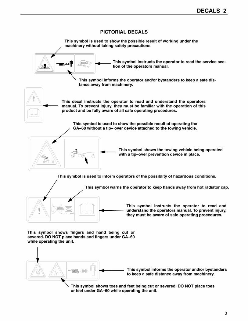
PICTORIAL DECALS
This decal instructs the operator to read and understand the operatorsmanual. To prevent injury, they must be familiar with the operation of thisproduct and be fully aware of all safe operating procedures.
This symbol shows fingers and hand being cut orsevered. DO NOT place hands and fingers under GA–60while operating the unit.
This symbol shows toes and feet being cut or severed. DO NOT place toesor feet under GA–60 while operating the unit.
This symbol instructs the operator to read andunderstand the operators manual. To prevent injury,they must be aware of safe operating procedures.
This symbol is used to show the possible result of operating theGA–60 without a tip– over device attached to the towing vehicle.
This symbol shows the towing vehicle being operatedwith a tip–over prevention device in place.
This symbol informs the operator and/or bystandersto keep a safe distance away from machinery.
This symbol is used to inform operators of the possiblity of hazardous conditions.
This symbol warns the operator to keep hands away from hot radiator cap.
This symbol instructs the operator to read the service sec-tion of the operators manual.
This symbol informs the operator and/or bystanders to keep a safe dis-tance away from machinery.
This symbol is used to show the possible result of working under themachinery without taking safety precautions.
2 DECALS
4
PICTORIAL DECALS
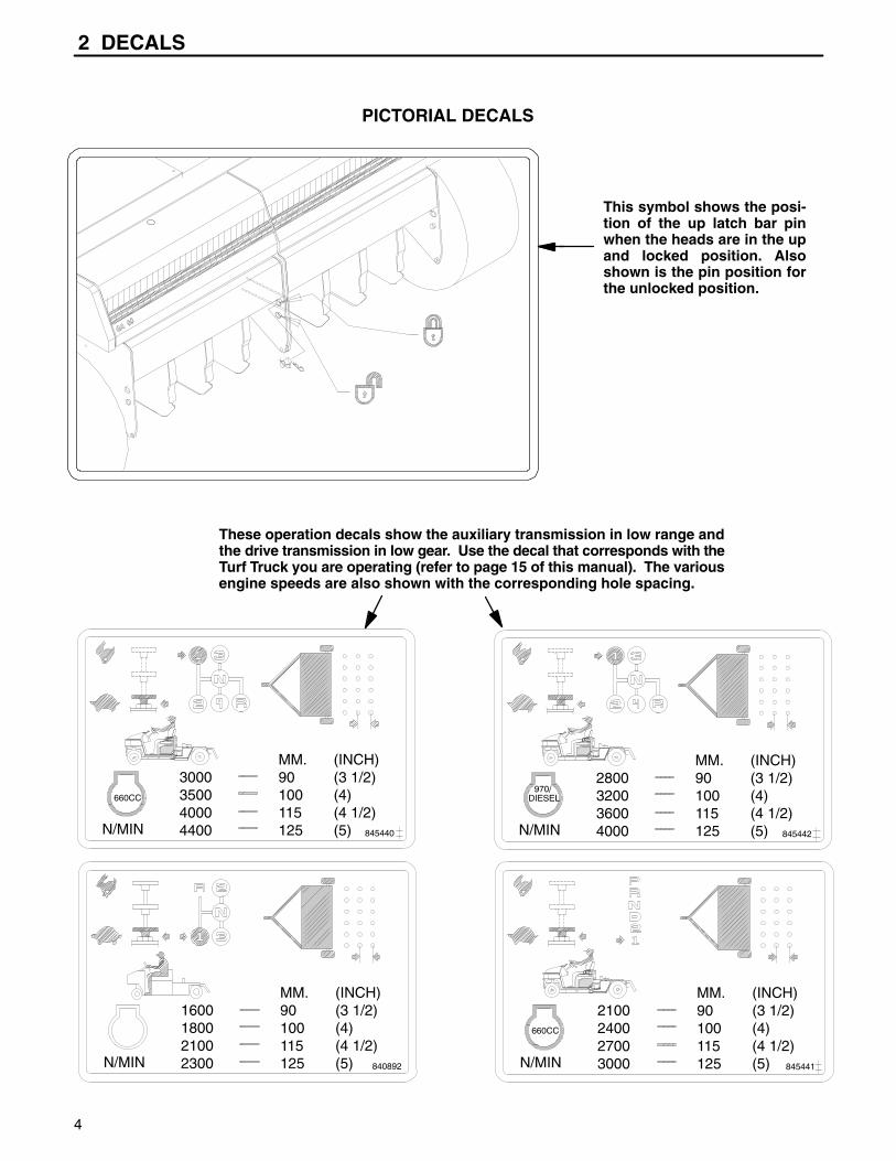
This symbol shows the posi-tion of the up latch bar pinwhen the heads are in the upand locked position. Alsoshown is the pin position forthe unlocked position.
These operation decals show the auxiliary transmission in low range andthe drive transmission in low gear. Use the decal that corresponds with theTurf Truck you are operating (refer to page 15 of this manual). The variousengine speeds are also shown with the corresponding hole spacing.
845441
2100240027003000
MM.90100115125
(INCH)(3 1/2)(4)(4 1/2)(5)N/MIN
660CC
845442
2800320036004000
MM.90100115125
(INCH)(3 1/2)(4)(4 1/2)(5)N/MIN
1600180021002300
MM.90100115125
(INCH)(3 1/2)(4)(4 1/2)(5)N/MIN 840892
845440
3000350040004400
MM.90100115125
(INCH)(3 1/2)(4)(4 1/2)(5)N/MIN
660CC
IDENTIFICATION 3
5
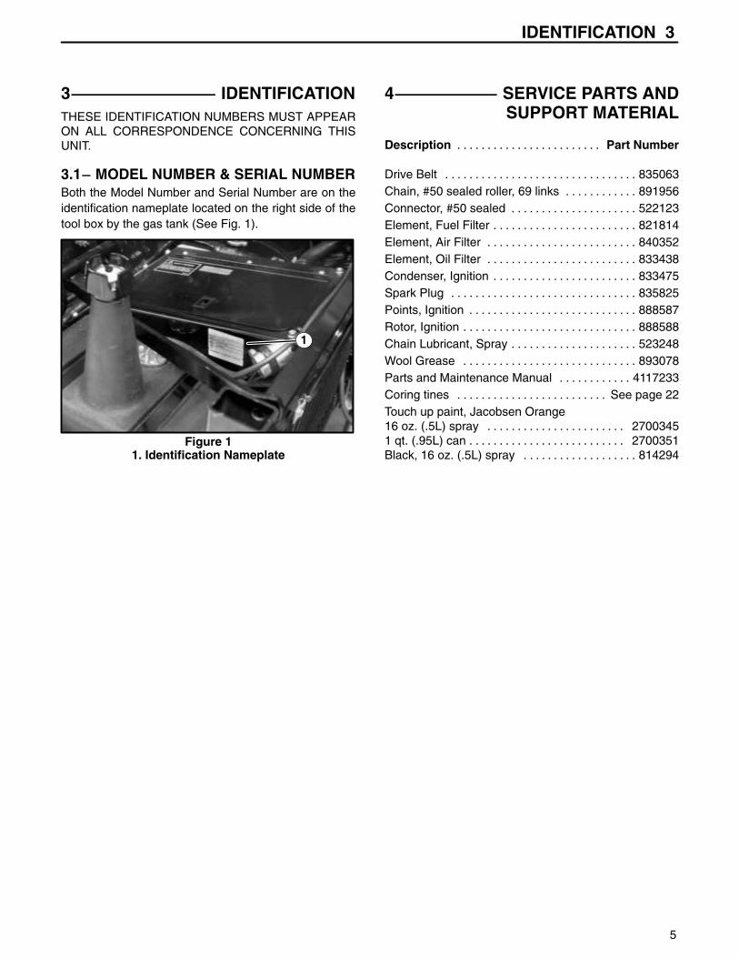
3 IDENTIFICATIONTHESE IDENTIFICATION NUMBERS MUST APPEARON ALL CORRESPONDENCE CONCERNING THISUNIT.
3.1 MODEL NUMBER & SERIAL NUMBERBoth the Model Number and Serial Number are on theidentification nameplate located on the right side of thetool box by the gas tank (See Fig. 1).
1
Figure 11. Identification Nameplate
4 SERVICE PARTS ANDSUPPORT MATERIAL
Description Part Number. . . . . . . . . . . . . . . . . . . . . . . .
Drive Belt 835063. . . . . . . . . . . . . . . . . . . . . . . . . . . . . . . . Chain, #50 sealed roller, 69 links 891956. . . . . . . . . . . . Connector, #50 sealed 522123. . . . . . . . . . . . . . . . . . . . . Element, Fuel Filter 821814. . . . . . . . . . . . . . . . . . . . . . . . Element, Air Filter 840352. . . . . . . . . . . . . . . . . . . . . . . . . Element, Oil Filter 833438. . . . . . . . . . . . . . . . . . . . . . . . . Condenser, Ignition 833475. . . . . . . . . . . . . . . . . . . . . . . . Spark Plug 835825. . . . . . . . . . . . . . . . . . . . . . . . . . . . . . . Points, Ignition 888587. . . . . . . . . . . . . . . . . . . . . . . . . . . . Rotor, Ignition 888588. . . . . . . . . . . . . . . . . . . . . . . . . . . . . Chain Lubricant, Spray 523248. . . . . . . . . . . . . . . . . . . . . Wool Grease 893078. . . . . . . . . . . . . . . . . . . . . . . . . . . . . Parts and Maintenance Manual 4117233. . . . . . . . . . . . Coring tines See page 22. . . . . . . . . . . . . . . . . . . . . . . . . Touch up paint, Jacobsen Orange16 oz. (.5L) spray 2700345. . . . . . . . . . . . . . . . . . . . . . . 1 qt. (.95L) can 2700351. . . . . . . . . . . . . . . . . . . . . . . . . . Black, 16 oz. (.5L) spray 814294. . . . . . . . . . . . . . . . . . .

5 SPECIFICATIONS
6
5 SPECIFICATIONS
(subject to change without notice)
Aerating Width:60” (1524 mm)
Engine:Bore – 2.62” (66.5 mm)Stroke – 3.19” (81 mm)Displacement – 51.7 cu. in. (847 cm3)Compression Ratio – 9.5:1Cylinder Compression – 213 PSI at 400 RPM (1486 KPa at 400 RPM)Horsepower – 33 h.p. at 3600 RPMEngine Rotation (viewed from flywheel) – counterclockwiseSpark Plug Gap – .032 (0.81 mm)Breaker Point Gap – .017 (0.43 mm)Ignition Timing – 0° BTDC at 1000 RPMIdle Speed – 1300 RPM (minimum)Valve Clearance – (Hot) Intake .010 (.25 mm) (Hot) Exhaust .012 (.30 mm)
Equipment Height: 42” (1067 mm)Equipment Length: 101” (2565 mm) (GA 60 alone)
172” (4369 mm) (with 3–wheel Turf–Truckster)Equipment Weight: 2209 lbs. (1002.8 kg) with
440 lbs. (199.7 kg) carried on Turf–TrucksterEquipment Width: 92” (2337 mm)Hole Spacing: 3 1/2” to 5” variable
(89 mm to 127 mm)Penetration Depth: 2 1/2” (64 mm) to 4” (102 mm)
maximum (depending on soil conditions)Truckster Speed: Engine: 2300 RPM (maximum
during aeration)Aeration: 1500 to 2300RPMTransport: Reasonable safe speed (10 mph max.)Use caution when towing aerator atspeeds above 5 M.P.H.
Standard Tines: Type: Hollow, tapered (self–cleaning)Material: Through hardened steelQuantity: 24 tines per unitSizes: 3/4” (19 mm)
Tires: Size: 23 – 10.50 x 12 High flotationRecommended Pressure – 18 psi
5.2 TOWING VEHICLE SPECIFICATIONS(Utility Vehicles)
NOTE: It is recommended that an 8720 or later modelCushman Turf–Truckster be used to tow and oper-ate the GA–60 aerator. The following towing vehiclespecifications must be met to insure proper and safeoperation of the GA–60.
Minimum towing vehicle weight – 1000 lbs. (454 kg)
Hitch height – approximately 31 1/4” (794 mm) for 9120and prior models and approximately 25” (635 mm) for9210 and later models.
Vibration dampening hitch required.
Mechanism to insure towing vehicle will not tip over back-wards when attached to GA–60.
Brakes – 7” (178 mm) hydraulic (minimum) on axle withmost weight.
Brake light system to power the electric brakes.
Hydraulic system requirements: 1800 psi minimumat 5 gallons per minute.
Variable speed governor (22 H.P. minimum engine size).
Mechanical transmission and drive to prevent change inground speed.
Ability to maintain constant 1–2 mph speed with gov-erned engine for 3 1/2” – 5” (89 mm to 127 mm) corespacing.
5.3 TOWING VEHICLE SPECIFICATIONS(Turf Utility Tractor)
Minimum weight of turf utility tractor – 2700 lbs. (1225kg).
12 volt negative ground electrical system.
Standard drawbar approved by tractor manufacturer.Drawbar height must be 13 – 19.7 inches (330–500 mm)from ground to top of drawbar.
Hydraulic system with 1800 to 2250 psi (12.4 to 15.5MPa) maximum pressure. Minimum output of 3 gallonper minute (11.4 L/min). Quick couplers located at rearof tractor.
Braking system capable of controlling the tractor and thetowed GA–60 weighing 2300 lbs. (1044 Kg).
Governor and properly geared transmission capable ofcontrolling ground speed from 1 to 2 mph (1.6 to 3.2km/hr) while aerating.
SET UP 6
7
6 SET UP
6.1 SET–UP INSTRUCTIONS FORCUSHMAN TURF–TRUCKSTER
IMPORTANT!
TO UTILIZE YOUR CUSHMAN TURF–TRUCKSTERAS A TOWING VEHICLE FOR THE GA–60, THE FOL-LOWING KITS/ACCESSORIES SHOULD FIRST BEINSTALLED ON THE TURF–TRUCKSTER:
1. Quick disconnect power cable installation kit (partsincluded in the GA–60 loose parts bag).
2. Hydraulic remote coupler kit (Part No. 889558) for9020 Turf–Truckster models and prior or hydraulicsystem for models 9110 and later.
3. Fifth wheel and electric brake control installation kit.
NOTE: To utilize 5th wheel implements not equippedwith tongue extensions on 8710–9120 model TurfTrucksters, use 5th wheel hitch kit (Part No.889623). To use 5th wheel implements equippedwith a tongue extension on 8710 & later Turf Truck-sters, use 5th wheel hitch kit (Part No. 890170).
4. Tachometer.
5. Variable speed governor.
6. Hydraulic system.
7. 3.2:1 ratio auxiliary transmission (9120 & prior).
8. 11.16:1 ratio 2–speed standard differential (9210 & later).
During transport with the aerator heads raised, the GA 60can be transported at any reasonable safe speed(10mph maximum) ALWAYS use extreme care whentowing aerator at any speeds above 5 mph.
6.2 POWER CABLE INSTALLATION
NOTE: These instructions are for persons using Cush-man Turf–Truckster (8720 and later) models898530, 898532, 898630, 898632, 898633 and898634 to tow their GA–60.
If using towing vehicle other than the Turf Trucksterslisted above, use good judgment in finding a suit-able mounting location for the power cable.
BE SURE there is adequate cable length to connectto the GA–60 and for turning either direction withoutdisconnecting the power cable.
WARNING!To prevent sparks, disconnect the negative (–)battery cable before installing power cable.
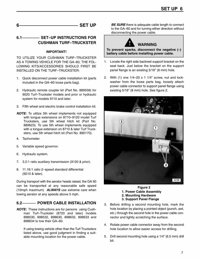
1. Locate the right side backrest support bracket on theseat back. Just below the bracket on the supportpanel flange is an existing 5/16” (8 mm) hole.
2. With (1) one 1/4–20 x 1 1/4” screw, nut and lock-washer from the loose parts bag, loosely attachpower cable connector to support panel flange usingexisting 5/16” (8 mm) hole. See figure 2.
1
2
3
4238
Figure 21. Power Cable Assembly2. Mounting Hardware3. Support Panel Flange
3. Before drilling a second mounting hole, mark thehole location by placing a pointed object (punch, awl,etc.) through the second hole in the power cable con-nector and lightly scratching the surface.
4. Rotate power cable connector away from the secondhole location to allow easier access for drilling.
5. Drill second mounting hole using a 1/4” (6.5 mm) drillbit.
6 SET UP
8
6. Rotate cable connector back to original position andsecure with (1) one 1/4–20 x 1 1/4” screw, lock-washer and nut from the loose parts bag. Tighten allhardware.
7. Connect eyelet end of black cable to vehicle framenegative ground location using existing hardware.
8. Using the existing hardware on the starter solenoid(located on the stopwall), connect the red cable endfrom power cable connector to the solenoid post thepositive cable from the battery is connected to.
9. Reconnect the negative (–) battery cable to the bat-tery.
6.3 TONGUE INSTALLATION
WARNING!To prevent possible injury to yourself or oth-ers, stay clear when cutting banding. Bandingis under tension and may snap back when cut.Wearing leather gloves or similar protectionwill help protect hands from sharp edges whenremoving banding from shipping pallet.
DO NOT operate equipment until you havethoroughly read and completely understandthe controls and operation sections of thismanual. If anything is not completely under-stood, contact your CUSHMAN dealer for clari-fication before operating equipment.
1. Loosen and raise left (facing front of unit) top coverand latch in the UP (raised) position.
2. Open air duct lid and remove loose parts bag fromtool box.
3. Carefully cut and remove all banding securing theGA–60 tongue components to the shipping pallet.
4. Turn jack handle counterclockwise to raise jack. Pulllocking pin from jack and swivel jack towards rear ofunit. Using the locking pin, lock the jack in the UP(raised) position.
CAUTION!The tongue components are very heavy. Toavoid injury, BE SURE to have assistancewhen lifting or moving any of these compo-nents.
5. Carefully slide tongue components out from undersides of GA–60 and remove from pallet.
6. Loosen the right side top cover panel and raise tilllatched in the UP (raised) position.
CAUTION!Use caution when removing upper side panelmounting screws. When screws are removedfrom panel, the panel inner support assemblywill become loose and could fall.
7. Remove both upper side panels, both lower panels,upper support assemblies and lower support brack-ets. Retain mounting screws.
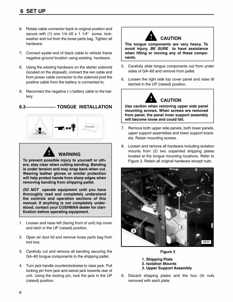
8. Loosen and remove all hardware including isolationmounts from (2) two unpainted shipping plateslocated at the tongue mounting locations. Refer toFigure 3. Retain all original hardware except nuts.
1
23
4244
Figure 3
1. Shipping Plate2. Isolation Mounts3. Upper Support Assembly
9. Discard shipping plates and the four (4) nutsremoved with each plate.

SET UP 6
9
10. With three (3) 5/8–11 x 4” hitch bolts, attach right sidetongue tube to main frame assembly. See Figure 4.Attach left side tongue tube to frame. Do not secureat this time.
1
2
5083
Figure 4
1. Tongue Tube2. Mounting Hardware
11. Using four (4) 5/8–11 x 5” screws, lockwashers, nutsand eight (8) thrust washers, attach short or longtongue extension to right and left tongue tubes. SeeFigures 5 and 6.
1
5084
Figure 5
1. Short Tongue Extension(used when towed w/turf–truckster)
12
5085
Figure 61. Long Tongue Extension(used when towed w/tractor)2. Hose Support
12. Torque the six (6) 5/8–11 x 4” hitch bolts to 120 ft.–lbs. (162 to 163 N⋅m). Torque the four (4) 5/8–11 x 5”screws to 120 ft.–lbs. (162 to 163 N⋅m).
NOTE: When using the long tongue extension, attachthe hose support to the tongue extension as shownin Figure 6.
13. Cut tie strap and uncoil hydraulic hoses, powercable, and control panel cable and route them downthe right (facing the front of unit) side of tongue,securing them with tie straps. The hoses should thenbe routed through the hose support on the fifth wheelof the towing vehicle.
6.4 HITCH COUPLER INSTALLATION
1. Raise the tool box lid and remove the hitch coupler.Attach the hitch coupler to the tongue extensionusing two (2) 1/2–13 x 4 1/4” screws, nuts and lock-washers.
2. Torque the two (2) screws to 75 ft.–lbs. (102 N⋅m).
6.5 REINSTALLING SIDE PANELS
1. Reinstall both upper side panels using all originalhardware except for nuts. Replace shipping nutswith new centerlock nuts from loose parts bag.
NOTE: For easier installation of the lower side coverpanel, attach the panel bracket to the inside of thepanel using double sided tape or a similar material.
2. Using original retained hardware, reinstall both lowerside cover panels.
3. Unlatch and lower both top cover panels and securein the DOWN (lowered) position.

6 SET UP
10
6.6 SET–UP INSTRUCTIONS FORTURF UTILITY TRACTOR
1. Install and secure a 2” (51 mm) tow hitch ball to the
standard tractor drawbar. BE SURE the hitch ball is
a class 2 (3500 lb. capacity) or better ball.
CAUTION!Use ONLY the standard drawbar approved bythe tractor manufacturer. The height from theground to the top of the drawbar must be 13 to19.7 inches (330–500 mm).
2. Mount power cable assembly (Part No. 889171) in a
suitable location at the rear of the tractor. Connect
the red cable end to the same post the tractor posi-
tive battery cable is attached to. Connect the black
cable to a good ground on the tractor frame. Refer to
wiring diagram.
NOTE: Cable lengths and eyelets may need to be modi-fied depending upon the configuration of your trac-tor.
3. Mount the GA–60 control panel at a location within
arms reach of the tractor operator. Connect the con-
trol box harness (Part No. 889174) to the GA–60
main harness (Part No. 889547). A wire harness
extension (Part No. 892790) may be used if addi-
tional wire harness length is required. This extension
is included in the long extension accessory (Part No.
892964).
4. The wheel brakes on the GA–60 are NOT USED
when towed with a turf utility type tractor. The brake
bypass jumper (Part No. 892793) must be plugged
into the wire assembly (Part No. 889052) on the
GA–60 control panel. See Figure 7. If the brake
bypass jumper is not installed, the GA–60 engine will
not start. Refer to wiring diagram.
1
2
5082
Figure 7
1. Brake Bypass
2. Control Panel
NOTE: The GA–60 brakes are not utilized therefore thetowing tractor must weigh a minimum 2700 lbs.(1225 Kg). The tractor brakes must be capable ofcontrolling the tractor and the 2300 lb. (1044 Kg)GA–60.
5. Determine what type and size hydraulic quick cou-plers are used on the towing tractor. Change theends on the GA–60 hydraulic hoses to match thetowing tractor hydraulic fittings. Add to hydraulichose length if required.
6. Attach long tongue extension to 2” (51 mm) hitchball on tractor draw bar. Route the wire harness,power cable and hydraulic hoses through the hosesupport mounted on the long tongue extension.
7. Connect wire harness, power cable and hydraulichoses to tractor. Remove GA–60 from pallet asdescribed in the following section.
8. With the GA–60 engine turned off and the heads inthe “UP” position, pull and turn the tractor fully to theleft and right. Make sure all hoses, wiring and hitchmove freely and are not rubbing against adjacentparts.
9. With the GA–60 heads in the “UP” position, disen-gage the uplatch bar shown in Figure 8. Start theGA–60, move to a turf area and lower the aeratorheads. Lowering the aerator heads will increase theGA–60 engine speed and will engage the aerator

SET UP 6
11
drive as it lowers. The aerator drive will disengageand engine will return to idle when the aerator headsare raised.
NOTE: If raising the hydraulic lever lowers the aerator,the hydraulic lines are reversed. Reverse thehydraulic lines at the quick couplers.
10. The GA–60 can produce a maximum hole spacing of5” (125 mm). Hole spacings larger than 5” (125 mm)will SEVERELY DAMAGE the aerator mechanism.
NOTE: The tractor speed MUST BE kept below 2 mph(3.2 km/hr) when aerating. BE SURE to use anengine speed and transmission gear that will resultin a hole spacing of less than 5” (127 mm). Aeratingspeeds exceeding the allowable 2 mph (3.2 km/hr)will SEVERELY DAMAGE the aerator mechanismcomponents.
HoleSpacing
MilesPer
Hour
2.5”
3.7”
5.0”2.0
1.5
1.068 seconds
51 seconds
34 seconds
Approximatetime needed to
drive 100’
Tractor Hole Spacing Chart
Inches(30.5 Meters) (Km/hr.) (mm)
During transport with the aerator heads raised, the GA 60can be transported at any reasonable safe speed(10mph maximum) ALWAYS use extreme care whentowing aerator at any speeds above 5 mph.
NOTE: The GA 60 may be damaged if towed on aflatbed trailer without the aerator heads lowered.Place boards or similar type material on the trailer toprevent damage to trailer and/or tines when theheads are lowered.
6.7 REMOVING FROM PALLET
1. Carefully cut and remove all banding securing aera-tor to shipping pallet.
2. Back the towing vehicle up to the GA–60. Positionthe towing vehicle so the tongue may be loweredonto the 5th wheel ball.
3. Loosen mounting clamp knob on rear of controlpanel to allow the control panel to be mounted on theright side hand hold of the Turf–Truckster or towingvehicle. Tighten mounting clamp knob to secure.
4. Connect control panel cable from GA–60 to right sideof control panel. Attach multi–pin connector from thebottom of the control panel to the connectormounted on the right stopwall support.
5. Lock the hydraulic lift control on the Turf–Trucksteror towing vehicle in the float position to relievehydraulic pressure. This will allow the hydraulichoses to be connected more easily.
NOTE: After connecting the hydraulic hoses, BE SUREto release the hydraulic lift control from the floatposition.
6. Connect the quick coupler power cable from theGA–60 to the Turf–Truckster or towing vehicle.
7. Start the Turf–Truckster or towing vehicle engine andraise the aerator heads slowly to lower the tongueonto the fifth wheel ball. Tighten ball grip to fifth wheelball by turning square nut on hitch coupler clockwiseuntil tight.
8. Raise aerator heads as high as possible to allowGA–60 to be removed from pallet.
NOTE: Place various thickness boards or blocks in frontof pallet to help prevent the GA–60 from dropping tothe ground from pallet during removal.
BE SURE aerator heads are raised to their maxi-mum height to assure the turf guards do not catchon pallet.
WARNING!DO NOT allow anyone to stand directly behindpallet during removal of the GA–60.
The weight of the unit may cause the pallet toslide back quickly when the GA–60 is removed.
9. Slowly drive the Turf–Truckster or towing vehicle for-ward to remove GA–60 from pallet.

6 SET UP
12
6.8 INSTALLING TINES
WARNING!DO NOT attempt to install tines with either theaerator or towing vehicle engine running.Remove key from towing vehicle and discon-nect power cable to GA 60 to insure that neitherengine can be started during tine installation.
Set parking brake on towing vehicle.
Before installing tines or performing any workunder the GA–60, always lock the uplatch barin place to prevent the accidental lowering ofthe aeration heads or the lowering of the headsdue to a loss in hydraulic pressure.
To lock uplatch bar, remove the pin under therear of the bar and move it to the upper hole,making sure the pin passes through theuplatch bar to lock it in place. See figure 8.
1
3
2
Figure 8
1. Uplatch Bar (Locked position)2. Pin3. Lower Hole
1. Insert three (3) tines per holder and torque screws(see torque chart). BE SURE tines are tight againstshoulder on tine holder. Open side of each tineshould be positioned towards the rear of the machinefor proper ejection of cores (See Fig. 9).
Figure 9
OPERATION 7
13
7 OPERATION7.1 PRE–OPERATION CHECK
1. Check grounds area and remove foreign objectswhich may be a hazard to the operator or could dam-age the equipment.
2. Visually check all moving parts and fasteners, if bro-ken or loose, replace or tighten. Check for broken orbent tines, replace as necessary.
3. Make sure that all shields and guards are in place.NEVER make adjustments or perform any mainte-nance while the engine is running.
4. BE SURE turf–truckster stabilizer tube is in placebefore operating GA–60. Refer to decal illustratedabove.
7.2 CONTROL PANEL
1 2
3
45
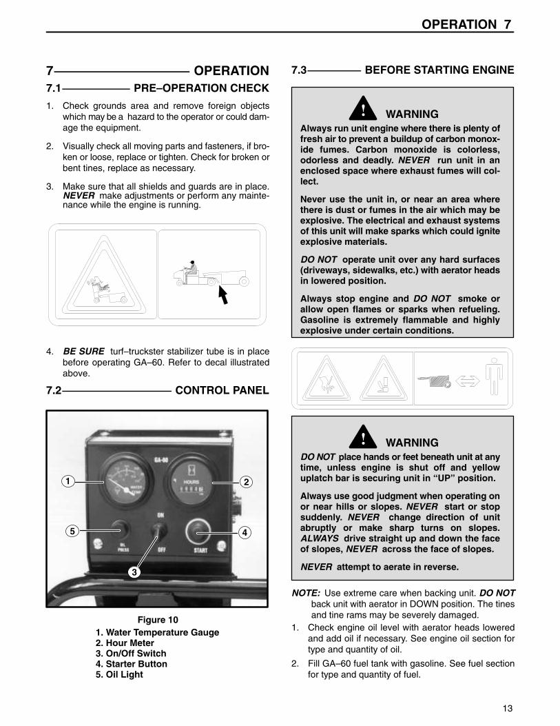
Figure 101. Water Temperature Gauge2. Hour Meter3. On/Off Switch4. Starter Button5. Oil Light
7.3 BEFORE STARTING ENGINE
WARNING!Always run unit engine where there is plenty offresh air to prevent a buildup of carbon monox-ide fumes. Carbon monoxide is colorless,odorless and deadly. NEVER run unit in anenclosed space where exhaust fumes will col-lect.
Never use the unit in, or near an area wherethere is dust or fumes in the air which may beexplosive. The electrical and exhaust systemsof this unit will make sparks which could igniteexplosive materials.
DO NOT operate unit over any hard surfaces(driveways, sidewalks, etc.) with aerator headsin lowered position.
Always stop engine and DO NOT smoke orallow open flames or sparks when refueling.Gasoline is extremely flammable and highlyexplosive under certain conditions.
WARNING!DO NOT place hands or feet beneath unit at anytime, unless engine is shut off and yellowuplatch bar is securing unit in “UP” position.
Always use good judgment when operating onor near hills or slopes. NEVER start or stopsuddenly. NEVER change direction of unitabruptly or make sharp turns on slopes.ALWAYS drive straight up and down the faceof slopes, NEVER across the face of slopes.
NEVER attempt to aerate in reverse.
NOTE: Use extreme care when backing unit. DO NOTback unit with aerator in DOWN position. The tinesand tine rams may be severely damaged.
1. Check engine oil level with aerator heads loweredand add oil if necessary. See engine oil section fortype and quantity of oil.
2. Fill GA–60 fuel tank with gasoline. See fuel sectionfor type and quantity of fuel.

7 OPERATION
14
7.4 GA–60 STARTING PROCEDURE1. Set ON/OFF toggle switch in “ON” position and
depress start button. Release start button as soon asengine starts. Allow approximately 5 minutes warmup time for engine before beginning aerating.
NOTE: NEVER depress start button while engine is run-ning. Starter drive and flywheel ring may be dam-aged.
CAUTION!To prevent possible breakage of hydraulic lift cylin-der brackets on frame, unit MUST BE resting ondown stops while aerating.
NEVER use the hydraulic lift cylinder to adjustdepth of aeration.
7.5 BEGINNING AERATION
WARNING!BE SURE electric brakes are working properlybefore beginning aeration. NEVER operate theGA–60 if the brakes are not adjusted correctly.Refer to electric brakes section.
1. Place the governor control lever in “DOWN” position.
2. Depress foot throttle pedal down to the floorboard.3. Refer to decal to obtain desired RPM and hole spac-
ing for the Turf Truckster you are operating.Decal 1: is for all Trucks manufactured prior to Aug.1998. (Check ID plate for year of manufacture.)Decal 2: is for Trucks with a 660 engine and manualtransmission.Decal 3: is for Trucks with a 970 or diesel engine withmanual transmission.Decal 4: is for Trucks with a 660 engine and auto-matic transmission.
4. Raise foot from throttle pedal to allow engine toreturn to idle speed.
5. Depress clutch pedal and place transmission gearselector in FIRST gear.
NOTE: Aerating in a higher gear will damage the aerat-ing mechanism and will also result in poor hole qual-ity.
6. Shift Turf–Truckster auxiliary transmission into LOWrange.
7. Slowly release clutch pedal to engage clutch whiledepressing foot throttle.
8. After reaching desired engine RPM’s, slowly pushhydraulic flow control lever down to lower aeratingheads and begin aeration.
845440
3000350040004400
MM.90100115125
(INCH)(3 1/2)(4)(4 1/2)(5)N/MIN
660CC
845442
2800320036004000
MM.90100115125
(INCH)(3 1/2)(4)(4 1/2)(5)N/MIN
845441
2100240027003000
MM.90100115125
(INCH)(3 1/2)(4)(4 1/2)(5)N/MIN
660CC
1600180021002300
MM.90100115125
(INCH)(3 1/2)(4)(4 1/2)(5)N/MIN 840892
DECAL 1
DECAL 2
DECAL 3
DECAL 4

OPERATION 7
15
7.6 AERATING DEPTH ADJUSTMENT
The GA–60 is designed to aerate at a MAXIMUM depthof 4” (102 mm). The operator should be aware that, inextremely hard soil, the machine may not be capable ofpushing the tines 4” (102 mm) into the ground. DO NOToperate with the depth setting at the 4” (102 mm) maxi-mum when the tines are only penetrating 2–3 inches(51–76 mm). Operating under these conditions willcause premature wear and/or broken components in theaerator linkage. If the aerator tires consistently ride up offthe turf or bounce up off the turf, the ground is too hard.
NEVER try to aerate at a depth greater than the soilconditions will allow. The operator must first make a testrun, measure the depth of the holes, and set the depthadjustment to correspond. After aerating the area onceor twice at that depth to loosen the sub–soil, it may bepossible to lower the settings each time until the 4” (102mm) maximum depth can be accomplished withoutabusing the GA–60.
AGAIN––Aerate a small test plot, measure the depth ofthe hole and adjust the depth setting on the GA–60 tomatch it.
If aerating extremely hard soil, additional penetration ispossible with added water, either by rain or irrigation.
Moist ground is easier to aerate than dry ground and isalso easier on the aerator mechanism.
If aerating in soil with rocks or stones, additional penetra-tion over time may not be possible. The operator mustdetermine what depth is possible for that area and besure he does not exceed that depth.
Adjusting the depth from 2 1/2” (64 mm) to 4” (102 mm) isaccomplished by adjusting the 1/2” (13 mm) axle stopspacers shown in Figure 11.
1
2
Figure 11
1. Downstop Block2. Spacers
8 MAINTENANCE
16
8 SERVICE AND MAINTENANCE
WARNING!When performing service or maintenance work on theGA 60, ALWAYS lock the uplatch bar in place to pre-vent the aeration heads from being lowered acciden-tally or due to a loss in hydraulic pressure. Set thepark brake on the tractor.
If any type of work is to be performed on the GA 60,disconnect the power cord and remove the key fromthe towing vehicle. This will prevent the GA 60 and thetowing vehicle from being accidentally started.
When replacement parts are required, use genuineRYAN parts or parts with equivalent characteristicssuch as type, strength and material. Failure to do somay result in product malfunction and possible injuryto the operator and/or bystanders.
NEVER attempt to perform service or maintenancefunctions on the GA 60 if you are UNTRAINED orUNAUTHORIZED. Improper maintenance can and willcause hazardous conditions. For necessary mainte-nance and service, contact your authorized RYANdealer.
When it is necessary to raise the GA 60PT for anyrepair or service, use jackstands to help provide ade-
quate support. DO NOT rely on hydraulic or mechani-cal jacks for support.
Immediately replace any warning and/or safety decalthat becomes damaged or difficult to read.
To reduce hazard of fire, always keep engine free ofexcessive grease. If fuel system leakage is detected,repair leak immediately. DO NOT operate unit untilleak is repaired. ALWAYS stop engine and do notallow open flames or sparks when performing anymaintenance function involving gasoline.
This product is heavy equipment and may present acrush hazard unless safety precautions are taken.
DO NOT operate equipment without all shields andguards in place.
To prevent possible injury, keep bystanders a safedistance away from machinery.
DO NOT make any adjustments or perform any main-tenance while the engine is running.
BE SURE to read the service section of this operatorsmanual and the parts and maintenance manual priorto performing any service work on this product.

MAINTENANCE 8
17
8.1 DAILY MAINTENANCE
1 Check the tire pressure (18 psi, 124 kPa).
2 BE SURE the weight is off of the tires. Lubricate axlepivots with a standard lithium based grease.
3 Lubricate aerator drive chains with chain lubricantspray (Part No. 523248).
4 Lubricate belt idler pivot with a standard lithiumbased grease.
5 Lubricate clutch linkage bellcrank with a standardlithium based grease.
6 Clean radiator intake screen.
7 Check radiator coolant level.
8 Check engine oil level.
LUBRICATION
1. Clutch Linkage2. Belt Idler3. Axle Yoke4. Axle Yoke5. Axle Yoke
⊗ ⊗ ⊗
⊗⊗
1
2
3
4
5
CHART
8.2 LUBRICATION FITTINGS
There are five (5) lubrication fittings that should be lubri-cated daily with a standard lithium based grease.
Three (3) fittings are located on the rear axle yokeassemblies. Refer to Figure 12 for lubrication points.
NOTE: When lubricating the rear axle yoke assemblies,the wheels should be off the ground and the weightshould be off the rear axle to allow proper lubricationof the yoke.
One (1) fitting is located on the clutch linkage pivot tube,and the fifth is located at the drive belt idler pivot.
The four (4) drive chains in the aerator head assemblyshould be sprayed with chain lubricant, spray (Part No.523248) each time the GA 60 is refueled, to greatlyextend chain life.
1
2
3
4242
FIGURE 12
1. Belt Idler Lube Fitting2. Clutch Linkage Lube Fitting3. Axle Yoke Lube Fittings (3)

8 MAINTENANCE
18
8.3 AIR CLEANER
This is a large capacity, dry type air cleaner with areplaceable paper element.
8.4 CHECKING ELEMENT
Check element for damage, pin holes, etc. by placing alight source such as a flashlight inside.
8.5 INSTALLING ELEMENT
1. Clean dust from inside of housing with a damp cloth.BE SURE dust does not enter intake.
2. Check all gaskets to make sure they are not loose ordamaged.
3. Insert element into housing as shown in Figure 13.
4. Apply a light grease film to the nylon washer andwing nut. Secure element with washer and wing nut.
NOTE: The dust collector empties automatically whenproperly installed with collector pointing DOWN.Refer to Figure 14 for proper positioning.
1
2
Figure 13
1. Filter Element2. Filter Housing
1
2
Figure 14
1. Filter Assembly2. Dust Collector
MAINTENANCE 8
19
8.6 FUEL SYSTEM
Fuel Capacity 10 gal. (45.4 L). . . . . . . . . . . . . . . . . . . Gasoline good grade of non–leaded only,. . . . . . . . . . . .
87 octane minimum
GASOLINE CONTAINING ALCOHOL
We DO NOT recommend the use of ALCOHOL bearingfuels in any of our products. The use of these fuels maycreate a potential safety hazard. See warning below.
WARNING!Gasoline containing ALCOHOL can causedeterioration of some non–metallic materialsin the fuel system.
Gasoline containing ALCOHOL will attract andhold moisture inside fuel tanks. Moisture maycause corrosion of metallic parts within thefuel system.
Fuel leakage from a fuel system, may occurwhile the system is in use, in transit, or in stor-age. Such leakage can contribute to an explo-sion or fire causing serious bodily injury ordeath.
NOTE: The use of alcohol bearing fuels may causeengine malfunction, particularly “vapor lock” at tem-peratures above 50° F (10° C).
WARNING!Remove fuel tank cap slowly. Fuel tank pres-sure may cause spray which can cause injury.
Gasoline is extremely flammable and highlyexplosive under certain conditions.
Never remove the fuel tank cap or attempt torefuel the GA–60 or Turf–Truckster while eitherengine is operating.
Never refuel indoors.
Always wipe up any spilled gasoline.
Never operate any equipment without anapproved gas cap on the fuel tank filler open-ing.
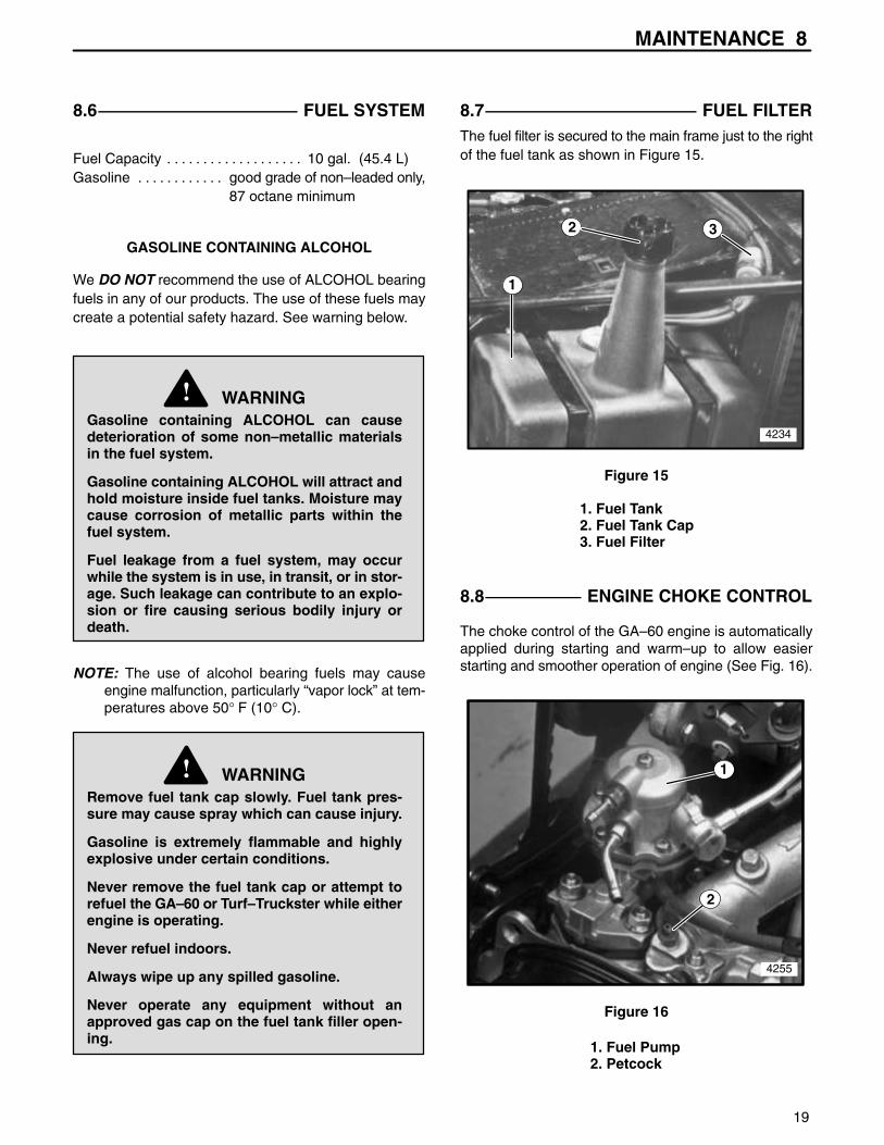
8.7 FUEL FILTERThe fuel filter is secured to the main frame just to the rightof the fuel tank as shown in Figure 15.
1
2 3
4234
Figure 15
1. Fuel Tank2. Fuel Tank Cap3. Fuel Filter
8.8 ENGINE CHOKE CONTROL
The choke control of the GA–60 engine is automaticallyapplied during starting and warm–up to allow easierstarting and smoother operation of engine (See Fig. 16).
4255
2
1
Figure 16
1. Fuel Pump2. Petcock

8 MAINTENANCE
20
8.9 ENGINE OIL
Engine Oil use only oils recommended. . . . . . . . . for service class SG or SH
Crankcase capacity 2.8 quarts (2.7 L). . . . . . . . . . . . . .
RECOMMENDED SAE VISCOSITY GRADES
Use SAE 10W30 SG or SH for all temperature ranges.
Using oil other than the service classes listed, or oil
change intervals longer than recommended, will greatly
reduce engine life. Damage caused by improper mainte-
nance such as incorrect oil quality and/or viscosity, are
not covered under Cushman warranty.
8.10 ENGINE OIL LEVEL
NOTE: The oil level must be maintained between thetwo marks on the dipstick at all times.
NEVER overfill engine oil. Overfilling engine oil willcause overheating and damage may result.
Engine oil should be checked with aerator headsdown, and the tines resting on the ground to obtainan accurate reading.
Checking oil level with the aerating heads in the“RAISED” position will give you inaccurate read-ings.
WARNING!To prevent possible explosion or ignition ofvaporized fuel, DO NOT store equipment withfuel in tank or carburetor in enclosure withopen flame (Example: Furnace or water heaterpilot light).
8.11 DRIVE CHAIN LUBRICATION
To prevent rust and prolong chain life, BE SURE thechains are well lubricated at all times. Use chain lubri-cant, spray (Part No. 523248).
8.12 TOWING
With the aerator heads raised, the GA 60 can be trans-ported at any reasonable safe speed (10mph maximum)ALWAYS use extreme care when towing aerator at anyspeeds above 5 mph.
NOTE: The GA 60 may be damaged if towed on aflatbed trailer without the aerator heads lowered.Place boards or similar type material on the trailer toprevent damage to trailer and/or tines when theheads are lowered.
8.13 TIRE PRESSURE
The recommended tire pressure is 18 psi. DO NOT oper-ate the GA 60 with over inflated or underinflated tires.
NOTE: Improper inflation will greatly shorten the life ofyour tires.
WARNING!Caution must be used when re–inflating orbringing a low tire to recommended pressure.Check air pressure with a gauge before con-necting an air hose to a partly inflated tire.
8.14 DAILY STORAGE
1. Inspect and clean tines, replace any broken or dam-aged tines as required.
2. Check engine oil level and add oil if needed.
3. Check for loose or missing hardware. Tighten orreplace as required before placing equipment backinto operation.

TINE HOLDERS 9
21
4116625.7
4116255.7
4117122.7 4116982.7
Tines Used W/Holder517486 1/4” Coring Tine517487 3/8” Coring Tine
Tine Holder 4117122.7 517488 1/2” Coring Tine547132 1/2” Carbide Tine
523995 1/2” H.D. Tine
Tines Used W/Holder517487 3/8” Coring Tine517489 5/8” Coring Tine
Tine Holder 4116255.7 523028 5/8” Coring Tine523421 3/8” Coring Tine523472 1/2” Coring Tine523394 5/8” Coring Tine
838323 1/2” Solid Tine
Tines Used W/HolderTine Holder 4116625.7 (Standard) (Standard) 834973 3/4” Coring Tine
523273 3/4” Coring Tine
Tines Used W/Holder*Tine Holder 4116982.7 523863 1/4” Solid Tine
523864 1/4” Coring Tine
(Use 7/8” o.d. tines)
(Use 3/4” o.d. tines)
(Use 1/2” o.d. tines)(Use 5/8” o.d. tines)
306416306325
523474
306435
306325
523474
548938
800446
523474
523474
306325
306435
*Turf guards (Part No. 4116983.7) must be used when using this tine holder.

10 TINES
22
PARTNUMBER
ACTUALLENGTH
CORING HOLESIZE APPLICATION
517486Coring Less penetration (use on hard soils).
517487Coring Less penetration (use on hard soils).
517488Coring Less penetration (use on hard soils).
517489Coring Less penetration (use on hard soils).
523028Coring
Older greens with high soil content, fairways & teeswith irrigation and no rocks.
523273Coring
Intensive fairway aerification or soil change ingreens. Soil must be in good condition.
523421Coring
Older greens with high soil content, fairways & teeswith irrigation and no rocks.
Older greens with high soil content, fairways & teeswith irrigation and no rocks.
For drought conditions or areas that won’t take water.For complete accessory, order Part No. 540115*.
TINES
More durable tine with less penetration (use wheretine wear rate is a problem).
838323Solid Tine
5 1/2”(140 mm)
547702(3/4” o.d.)
1/2” x 3 3/4”(13 mm x 95 mm)
Heavy aeration when no clean up is desired.
523864Coring
1/4” x 2 1/2”(6 mm x 64 mm)
547848(1/2” o.d.)
4”(102 mm)
523863Solid Tine
5”(127 mm)
1/4” x 3 1/8”(6 mm x 79 mm)
547848(1/2” o.d.)
547132Carbide Tip
4 1/2”(114 mm)
1/2” x 2 1/2”(13 mm x 64 mm)
547601(5/8” o.d.)
523472Coring
5 1/2”(140 mm)
1/2” x 3 3/4”(13 mm x 95 mm)
547702(3/4” o.d.)
5”(127 mm)
3/8” x 3 1/4”(10 mm x 83 mm)
547702(3/4” o.d.)
5 1/2”(140 mm)
3/4” x 3 3/4”(19 mm x 95 mm)
547639(7/8” o.d.)
5 1/2”(140 mm)
5/8” x 3 3/4”(16 mm x 95 mm)
547702(3/4” o.d.)
4 1/4”(108 mm)
5/8” x 2 1/2”(16 mm x 64 mm)
547702(3/4” o.d.)
4 1/4”(108 mm)
1/2” x 2 1/2”(13 mm x 64 mm)
547601(5/8” o.d.)
4 1/4”(108 mm)
3/8” x 2 1/2”(13 mm x 64 mm)
547601(5/8” o.d.)
4 1/4”(108 mm)
1/4” x 2 1/2”(6 mm x 64 mm)
547601(5/8” o.d.)
834973Coring
524419Coring
523995Coring H.D.
4 1/4”(108 mm)
1/2” x 2 1/2”(13 mm x 64 mm)
547601(5/8” o.d.)
5 1/2”(140 mm)
5/8” x 3 3/4”(16 mm x 95 mm)
547702(3/4” o.d.)
5 1/2”(140 mm)
3/4” x 3 3/4”(19 mm x 95 mm)
547639(7/8” o.d.)
*
523863 523995517489517488
523864 523421517487517486
524419834973
523028523273547132
523472838323
Some of the tines illustrated have more than one part number listed below them. These tines are similar indesign but may vary in length and/or diameter, for example: Part No. 523995 (coring tine) is 4 1/4” long with acoring hole of 1/2” x 2 1/2’ and Part No. 517489 (coring tine) also 4 1/4” long, has a coring hole of 5/8 x 2 1/2”.
TINE HOLDERUSED
Illustrations are for reference only.
Primarily used for light aeration for soil–based greensand for overseeding. For complete accessory, orderPart No. 540387.**
Heavy duty tine with less penetration. Use on hardsoils, sports turf.
Fairway & tee boxes with irrigation and no rocks.Renovation of sports turf.
Intensive aerification or soil or soil change. Soil must beirrigated and in good condition. Standard GA–60 tine.
540115 Quint Solid Tine Accessory (includes tines, holder and turf guard).*540387 Quint Coring Tine Accessory (includes tines, holder and turf guard).**

TORQUE CHART 11
23
M4 M5 M6 M7 M8 M10 M12 M14 M16 M18 M20 M22 M24 M27
ft. lbs. 1.5 3 5.2 8.2 13.5 24 43.5 70.5 108 142 195 276 353 530
N·m 2 4 7 11 18 32 58 94 144 190 260 368 470 707
ft. lbs. 2.2 4.5 7.5 12 18.8 35.2 62.2 100 147 202 275 390 498 747
N·m. 3 6 10 16 25 47 83 133 196 269 366 520 664 996
ft. lbs. 2.7 5.2 8.2 15 21.8 43.5 75 119 176 242 330 471 596 904
N·m 3.6 7 11 20 29 58 100 159 235 323 440 628 794 1205
1/4 5/16 3/8 7/16 1/2 9/16 5/8 3/4 7/8 1 1 1/8
ft. lbs. 9 18 31 50 75 110 150 250 378 583 782
N·m 12 24 42 68 102 150 203 339 513 790 1060
ft. lbs. 13 28 46 75 115 165 225 370 591 893 1410
N·m 18 38 62 108 156 224 305 502 801 1211 1912
ft. lbs. 24 40
N·m 33 54
TORQUE SPECIFICATIONSHEX HEAD CAP SCREWS
* Grade 5 marking – Minimum commercial quality (Lower quality not recommended).
U.S. Standard Hardware
GradeShank Size (Diameter in inches, fine or coarse thread)
SAE
grade5 *SAE
grade8 **
FlangelockScrew w/
FlangelockNut
The torque values shown should be used as a general guideline when specific torque values are not given.
** Grade 8 marking –
GradeShank Size (Diameter in millimeters, fine or coarse thread)
Grade8.8*
Grade10.9**
Grade12.9 ***
Metric Standard Hardware
* Grade 8.8 marking – ** Grade 10.9 marking – *** Grade 12.9 marking –8.8 10.9 12.9
24
INDEX
Aerating Depth Adjustment 15. . . . . . .
Aeration, Beginning 14. . . . . . . . . . . . . .
Air Cleaner 18. . . . . . . . . . . . . . . . . . . . .
Before Starting Engine 13. . . . . . . . . .
Beginning Aeration 14. . . . . . . . . . . . . .
Checking Element 18. . . . . . . . . . . . . .
Choke Control 19. . . . . . . . . . . . . . . . . .
Control Panel 13. . . . . . . . . . . . . . . . . . .
Daily Maintenance 17. . . . . . . . . . . . . .
Decals 3, 4. . . . . . . . . . . . . . . . . . . . . . . .
Depth Adjustment 15. . . . . . . . . . . . . . .
Drive Chain Lubrication 20. . . . . . . . . .
Engine Choke Control 19. . . . . . . . . . .
Engine Oil 20. . . . . . . . . . . . . . . . . . . . . .
Fuel Filter 19. . . . . . . . . . . . . . . . . . . . . .
Fuel System 19. . . . . . . . . . . . . . . . . . . .
Hitch Coupler Installation 9. . . . . . . . .
Identification 5. . . . . . . . . . . . . . . . . . . . .
Installing Element 18. . . . . . . . . . . . . . .
Installing Tines 12. . . . . . . . . . . . . . . . . .
Lubrication Chart 17. . . . . . . . . . . . . . .
Lubrication Fittings 17. . . . . . . . . . . . . .
Maintenance 16. . . . . . . . . . . . . . . . . . .
Model Number 5. . . . . . . . . . . . . . . . . . .
Oil, Engine 20. . . . . . . . . . . . . . . . . . . . .
Operation 13. . . . . . . . . . . . . . . . . . . . . .
Operation Safety 2. . . . . . . . . . . . . . . . .
Power Cable Installation 7. . . . . . . . . .
Pre–Operation Check 13. . . . . . . . . . . .
Reinstalling Side Panels 9. . . . . . . . . .
Removing From Pallet 11. . . . . . . . . . .
Safety, Operation 2. . . . . . . . . . . . . . . .
Serial Number 5. . . . . . . . . . . . . . . . . . .
Service Parts and Support Material 5.
Set Up 7. . . . . . . . . . . . . . . . . . . . . . . . . .
Set Up Tractor 10. . . . . . . . . . . . . . . . . .
Set Up Turf Trucks 7. . . . . . . . . . . . . . .
Side Panels, Reinstalling 9. . . . . . . . . .
Specifications 6. . . . . . . . . . . . . . . . . . . .
Specifications, Tractor 6. . . . . . . . . . . .
Specifications, Truck 6. . . . . . . . . . . . . .
Starting Engine, Before 13. . . . . . . . . .
Starting GA 60 14. . . . . . . . . . . . . . . . . .
Storage 20. . . . . . . . . . . . . . . . . . . . . . . .
Tine Holders 21. . . . . . . . . . . . . . . . . . .
Tine Installation 12. . . . . . . . . . . . . . . . .
Tines 22. . . . . . . . . . . . . . . . . . . . . . . . . .
Tires 20. . . . . . . . . . . . . . . . . . . . . . . . . . .
Tongue Installation 8. . . . . . . . . . . . . . .
Torque Chart 23. . . . . . . . . . . . . . . . . . . .
Towing 20. . . . . . . . . . . . . . . . . . . . . . . . .
Tractor Specifications 6. . . . . . . . . . . . .
Truck Specifications 6. . . . . . . . . . . . . .
Warranty 24-26. . . . . . . . . . . . . . . . . . .

WARNING! !
The engine exhaust from this productcontains chemicals known to the State ofCalifornia to cause cancer, birth defectsor other reproductive harm.
L’émission du moteur de ce matérielcontient des prouits chimiques quel’Etat de Californie considère êtrecancérigènes, provoquer desdéfauts congénitaux et d’autresdangers en matière de reproduction.
Advertissement
El estado de California hace saberque los gases de escape de esteproducto contienen productos quÍmi-cos que producen cáncer, defectosde nacimiento y otros daños en elproceso de repeoducción humana.
Advertencia!

Textron Golf, Turf & Specialty ProductsPO Box 7708, Charlotte, NC 28241-7708www.ttcsp.com
,


