Capacity to 310 GPM/70 M 3/ hr Pressure to 500 PSI/34 Bar Viscosity to 910,000 SSU (200,000 cSt) Temperature -40° to 300° F (-40° to 150° C) SANITARY POSITIVE DISPLACEMENT PUMPS TRA 20 Series ®
Transcript
Capacity to 310 GPM/70 M3/hr
Pressure to 500 PSI/34 Bar
Viscosity to 910,000 SSU (200,000 cSt)
Temperature -40° to 300° F (-40° to 150° C)
S A N I TA RY P O S I T I V E D I S P L A C E M E N T P U M P S
TRA 20 Ser ies®
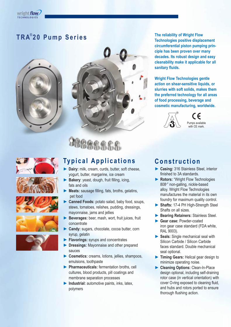
The reliability of Wright Flow
Technologies positive displacement
circumferential piston pumping prin-
ciple has been proven over many
decades. Its robust design and easy
cleanability make it applicable for all
sanitary fluids.
Wright Flow Technologies gentle
action on shear-sensitive liquids, or
slurries with soft solids, makes them
the preferred technology for all areas
of food processing, beverage and
cosmetic manufacturing, worldwide.
Pumps available with CE mark.
► Dairy: milk, cream, curds, butter, soft cheese,
yogurt, butter, margarine, ice cream
► Bakery: yeast, dough, fruit filling, icing,
fats and oils
► Meats: sausage filling, fats, broths, gelatins,
pet food
► Canned Foods: potato salad, baby food, soups,
stews, tomatoes, relishes, pudding, dressings,
mayonnaise, jams and jellies
► Beverages: beer, mash, wort, fruit juices, fruit
concentrate
► Candy: sugars, chocolate, cocoa butter, corn
syrup, gelatin
► Flavorings: syrups and concentrates
► Dressings: Mayonnaise and other prepared
sauces
► Cosmetics: creams, lotions, jellies, shampoos,
emulsions, toothpaste
► Pharmaceuticals: fermentation broths, cell
cultures, blood products, pill coatings and
membrane separation processes
► Industrial: automotive paints, inks, latex,
polymers
T R A®2 0 P u m p S e r i e s
Ty p i c a l A p p l i c a t i o n s C o n s t r u c t i o n► Casing: 316 Stainless Steel, interior
finished to 3A standards.
► Rotors: “Wright Flow Technologies 808®” non-galling, nickle-based alloy. Wright Flow Technologies manufactures the material in its own foundry for maximum quality control.
► Shafts: 17-4 PH High-Strength Steel Shafts on all sizes.
► Bearing Retainers: Stainless Steel.
► Gear case: Powder-coated iron gear case standard (FDA white, RAL 9003).
► Seals: Single mechanical seal with Silicon Carbide / Silicon Carbide faces standard. Double mechanical seal optional.
► Timing Gears: Helical gear design to minimize operating noise.
► Cleaning Options: Clean-In-Place design optional, including self-draining rotor case (in vertical orientation) with cover O-ring exposed to cleaning fluid, and hubs and rotors ported to ensure thorough flushing action.
The mounting foot may be moved to any of four positions to allow horizontal or vertical porting and flexibility of driver connection.
P e r f o r m a n c eR a n g e
► Capacity Range: 0.1 to 310 gpm
(0.02 to 70.4 m3/hr)
► Pressure Range: to 500 PSI/34 Bar
► Temperature Range: -40°F to +300°F
(-40°C to +150°C)
Note: Hot clearances required for
high temp operation
► Viscosity Range: 28 to 910,000 SSU
(1 to 200,000 cSt)
Note: Consult factory for applications
greater than 910,000 SSU/200,000 cSt.
Chocolate clearances available.
Other port configuration
options include:
► DIN 11851
► RJT
► NPT
► SMS
► 150# or 300# flange
TRA®20Model
Nominal Capacity
Displacementper Revolution
Maximum Pressure
TemperatureRange
ViscosityRange
StandardPorts
OptionalPorts
MaximumSpeed
(RPM)GPM M³/hr Gal. Liter PSI Bar Deg. F Deg. C SSU cSt in. mm in. mm
0060 8 1.8 .008 .030 300 21 -40° to 300° * -40° to 150° * 28 to 910,000 1 to 200,000 1.0 25.4 1.5 38 1000
0150 11 2.5 .014 .052 250 17 -40° to 300° * -40° to 150° * 28 to 910,000 1 to 200,000 1.5 38.0 — — 800
0180 20 4.5 .029 .108 200 14 -40° to 300° * -40° to 150° * 28 to 910,000 1 to 200,000 1.5 38.0 2.0 51 700
0300 36 8.2 .060 .227 250 17 -40° to 300° * -40° to 150° * 28 to 910,000 1 to 200,000 1.5 38.0 2.0 51 600
0450 58 13.2 .096 .366 450 31 -40° to 300° * -40° to 150° * 28 to 910,000 1 to 200,000 2.0 51.0 — — 600
0600 90 20.4 .150 .568 300 21 -40° to 300° * -40° to 150° * 28 to 910,000 1 to 200,000 2.5 64.0 3.0 76 600
1300 150 34.1 .250 .946 200 14 -40° to 300° * -40° to 150° * 28 to 910,000 1 to 200,000 3.0 76.0 — — 600
1800 230 52.2 .383 1.45 450 31 -40° to 300° * -40° to 150° * 28 to 910,000 1 to 200,000 3.0 76.0 — — 600
2100 300 68.1 .500 1.89 500 34 -40° to 300° * -40° to 150° * 28 to 910,000 1 to 200,000 4.0 102.0 — — 600
2200 310 70.4 .516 1.95 300 21 -40° to 300° * -40° to 150° * 28 to 910,000 1 to 200,000 4.0 102.0 — — 600
* Hot clearances required for high temperature operation.
Sanitary Clamp Bevel Seat (ACME)
TRA®20Rectangular
Flange Model
Nominal Capacity
Displacement per Revolution
Maximum Pressure
TemperatureRange
Inlet (W x L) Outlet Maximum
Speed
(RPM)GPM M³/hr Gal. Liter PSI Bar Deg. F Deg. C in. mm in. mm
0240 11.6 2.5 .03 .11 200 14 -40° to 300° -40° to 150° 1.31 x 4.63 33.27 x 125.22 1.5 38.1 400
0340 24.0 5.4 .06 .23 200 14 -40° to 300° -40° to 150° 1.75 x 6.75 44.50 x 171.45 1.5 38.1 400
0640 60.0 13.6 .15 .57 200 14 -40° to 300° -40° to 150° 2.24 x 8.82 56.90 x 224.03 2.5 57.15 400
1340 100.0 22.7 .25 .95 200 14 -40° to 300° -40° to 150° 2.97 x 9.25 75.44 x 234.95 3.0 76.2 400
2240 200.0 45.4 .52 1.95 200 14 -40° to 300° -40° to 150° 3.87 x 11.00 98.30 x 279.40 4.0 101.6 400
Horizontal ports, bottom shaft position
Horizontal ports, top shaft position
Vertical ports, left-hand or right-hand shaft position(required for CIP design)
T R A®2 0 P u m p P e r f o r m a n c e
I n s t a l l a t i o n P o s i t i o n s 4-Way Mounting
P o r t C o n f i g u r a t i o n s
► Time tested and proven circumferential piston design.
► Exceptional engineering and manufacturing quality.
► Parts are interchangeable with Waukesha® U2 series
pump parts.
► Wright Flow Technologies TRA®20 pumps are drop-in
replacements for equivalent sized Waukesha® U2 pumps.
► Wright Flow Technologies can remanufacture TRA®20
series or Waukesha® U2 series pumps up to three times.
Choosing between TRA®20 and TRA®10 series pumps
► The TRA®20 series allows optional Clean-In-Place design.
CIP-ing can reduce cleaning time and labor between
batches, for maximum productivity.
► Most TRA®20 models offer higher pressure capabilities than
their equivalent TRA®10 model, all of which are rated to
200 PSI (14 Bar), except the model TRA®10 0450, which is
rated to 400 PSI (27 Bar).
Helical timing gears offer
higher load carrying capabilities
and reduce noise for
quieter operation.
Hard-faced SiC/SiC
single mechanical seals
standard. Double seals
with flush optional.Durable powdercoated
gearbox standard. Helps
prevent flaking and corrosion
common to painted
gearboxes.
Four-way gear case
mounting allows
horizontal or vertical
porting, plus flexibility
to position drive shaft
to match reducer or
gearmotor input.
Rotor retainers are tensioned by
Belleville washers to prevent loosening.
Both rotors and rotor retainers have
O-ring seals to ensure CIP-ability.
Optional porting for CIP models
to allow vigorous flushing throughout
all internal chambers.
Stainless steel bearing retainers standard.
Prevents rusting common to carbon steel bearing
retainers used by others.
Threaded grease fittings (not push-in)
prevent dislodging. Access on both sides
of pump makes greasing easier.
►►►
►
►►
►
►
Intelligent oil plug positioning on back of
pump helps keep washdown spray out of
gearbox oil.
T R A®
2 0 F e a t u r e s
►►
►
►►►
►
►
►
►
Single Mechanical Seals
► Standard Seal Faces: SiC/SiC
► Standard O-rings and Cover Seals: Buna
► Optional Faces: Carbon, Ceramic or
Chrome Oxide
► Optional O-rings and Cover Seals:
FKM, EPDM, Silicone
Double Mechanical Seals with Flush
► Standard Seal Faces: SiC/SiC
► Standard O-rings and
Cover Seals: Buna
► Optional Faces: Carbon, Ceramic
or Chrome Oxide
► Optional O-rings and Cover Seals:
FKM, EPDM, Silicone
Waukesha® is a Registered Trademark of United Dominion Industries/SPX Corp.
S h a f t S e a l i n g O p t i o n s…for different liquids and conditions of service
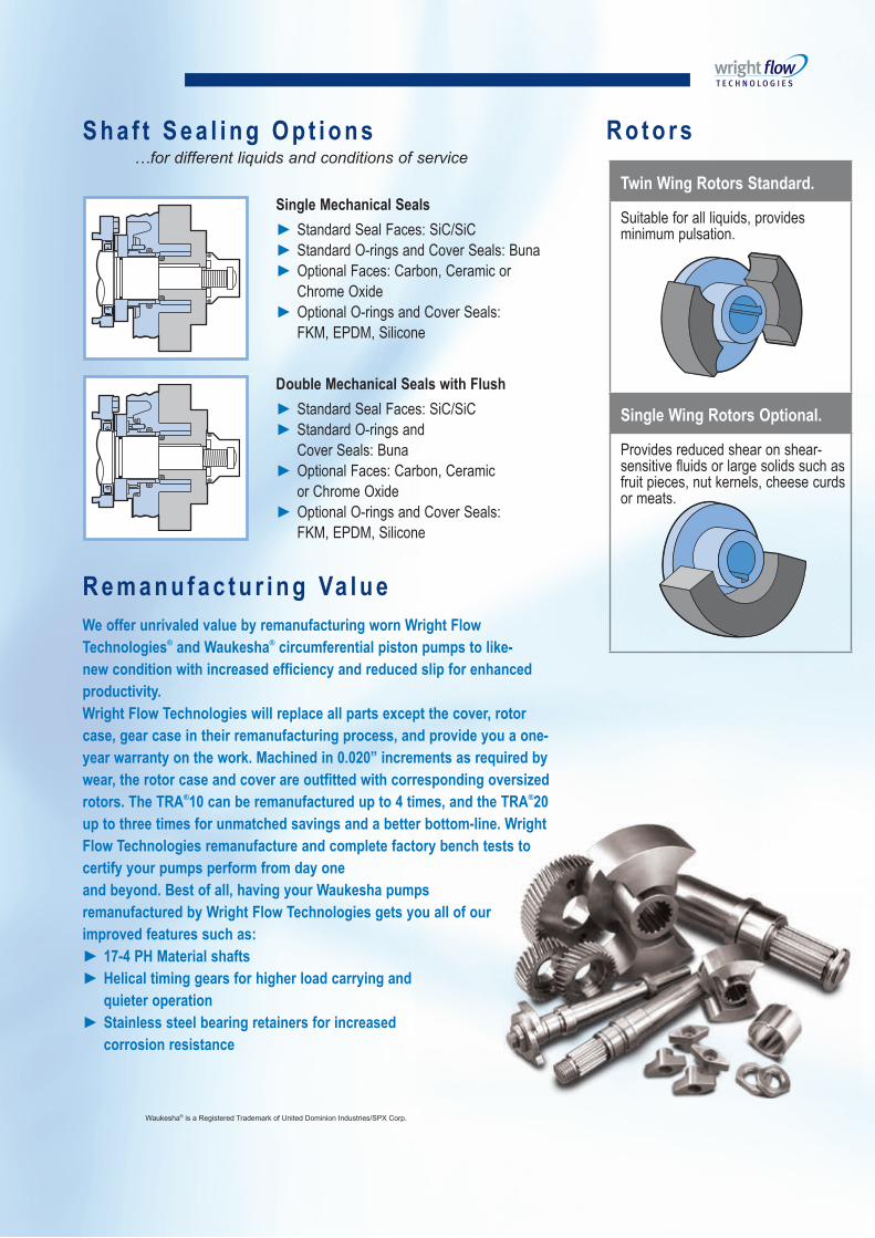
R o t o r s
Twin Wing Rotors Standard.
Suitable for all liquids, provides minimum pulsation.
Single Wing Rotors Optional.
Provides reduced shear on shear- sensitive fluids or large solids such as fruit pieces, nut kernels, cheese curds or meats.
R e m a n u f a c t u r i n g Va l u e
We offer unrivaled value by remanufacturing worn Wright Flow
Technologies® and Waukesha® circumferential piston pumps to like-
new condition with increased efficiency and reduced slip for enhanced
productivity.
Wright Flow Technologies will replace all parts except the cover, rotor
case, gear case in their remanufacturing process, and provide you a one-
year warranty on the work. Machined in 0.020” increments as required by
wear, the rotor case and cover are outfitted with corresponding oversized
rotors. The TRA®10 can be remanufactured up to 4 times, and the TRA®20
up to three times for unmatched savings and a better bottom-line. Wright
Flow Technologies remanufacture and complete factory bench tests to
certify your pumps perform from day one
and beyond. Best of all, having your Waukesha pumps
remanufactured by Wright Flow Technologies gets you all of our
improved features such as:
► 17-4 PH Material shafts
► Helical timing gears for higher load carrying and
quieter operation
► Stainless steel bearing retainers for increased
corrosion resistance
Wright Flow Technologies rotor
wings (pistons) rotate around the
circumference of the channel in the
pump casing. This continuously
generates a partial vacuum at the
suction port as the rotors unmesh,
causing fluid to enter the pump.
The fluid is transported around the
channel by the rotor wings, and
is displaced as the rotor wings
converge, generating pressure at the
discharge port. Pump output
is directly proportional to speed,
and direction of flow is reversible.
Suction Discharge
A B C
The deep channels in which the rotors travel
provide large voids to minimize shear and
bruising of solids.
The rotors are made of “Wright Flow
Technologies 808®” non-galling alloy, allowing
extremely tight clearances between rotating and
stationary surfaces, which ensures high efficiency
and metering accuracy, even on thin liquids.
The forward part of each non-galling rotor
rotates in a recess in the pump head to minimize
deflection even at high discharge pressures.
Wright F low Techno log ies Pos i t i ve D isp lacement
C i rcumferen t ia l P is ton Pumping Pr inc ip le
In this large void,
solids are not
bruised.
Model A B C D E F G H I J K L M N O P Q Ø R S Weight
mm 216 94 229 610 314 95 184 14 x 5 (slot) 357 162 470 114 70 238 102 113 50.80 168 337 252 kg
S
R J
D
K
M
LJ
E
Q
L
P G
I
CB
F
O
F
N
H
A
OPTIONALFOOTLOCATION
Disclaimer: Dimensions are for guidance only. Please refer to our technical office if a certified drawing is required.
T R A®2 0 D i m e n s i o n s
FM
T A
CO
/WF
T/A
4 T
RA
20/1
24
San i ta ry Pumps , Par ts , Remanufac tur ing & Accessor ies
Form No. WFT-TRA20
Remanufactur ing in Europe and North Amer ica
Wright Flow Technologies offers unique remanufacturing services in Europe and North America for Waukesha®
Universal I and Universal II series pumps, as well as Wright Flow Technologies TRA10 and TRA20 series pumps.
Remanufacturing is a lower-cost alternative to buying a new replacement pump and it gets you all of Wright Flow
Technologies improved features and beneits. Ask your distributor, or the factory for more details.
Wright F low Technologies
Our products are used across the whole of the process industries in applications as diverse as paper & pulp pro-
duction through to the extreme hygiene end of the pharmaceutical industry on injectables and blood processing. We
manufacture within our organization rotary lobe, centrifugal, circumferential piston, air operated double diaphragm
and dosing pumps, all manufactured and designed with hygiene, cleanliness, affordability and robustness in mind.
These pumps coupled with our range of hygienic turbine and magnetic low meters, our full range of sanitary valves and our powder mixing technology from Quadro, gives a complete package for the modern high-tech process indus-


![YTA310, YTA320 Temperature Transmitter · SAMA RC21-4-70 to 150 -94 to 302-70 to -40-40 to 150-94 to -40-40 to 302 ±1.35 ±1.0 ±2.43 ±1.8 mV —-10 to 100 [mV] 3 [mV] — ±12](https://static.documents.pub/doc/80x56/5f2cc81c075c7b51b3150172/yta310-yta320-temperature-transmitter-sama-rc21-4-70-to-150-94-to-302-70-to-40-40.jpg)


