low acidity outer layer by epitaxialgrowth and its improved MTO performance
Chuiyan Kong, Jiang Zhu, Senyuan Liu and Yao Wang *
Although it is known that a low-silica SAPO-34 zeolite gives goodMTO performance, the direct synthesis of
a SAPO-34 zeolite with a low acid site density suffers from the problem of low yield and impure crystallinity.
In this work, SAPO-34 zeolite samples with an appropriate low acid site density were synthesized as a low
acid site outer layer on a high acid site core by epitaxial growth using a two-step hydrothermal synthesis.
The samples were characterized by SEM, TEM, EDS-lining, XRD, ICP, XPS, TPD-NH3, TGA-Py and Ar
adsorption. EDS-lining confirmed a silica distribution of a high-silica core and low-silica outer layer in
the two-step synthesized SAPO-34 particles, and determined the thickness of low-silica outer layer to
be 200 nm. The two-step synthesized samples have the CHA structure and gave good molecular sieve
selectivity. The second-step growth used a low concentration of silica in the source to decrease the
Si/Al ratio of the bulk solid phase, leading to the reduction of acid site density. Catalytic activity
evaluation in a microreactor revealed that the two-step synthesized SAPO-34 zeolite gave both better
MTO performance and hydrothermal stability compared to a zeolite produced by the one-step synthesis.
The low acid site outer layer of the two-step synthesized samples had reduced coking and diffusion
limitation, resulting in increased lifetime. This work provides a practical catalyst synthesis strategy of
SAPO-34 catalysts for the MTO industry, by showing that a small high-silica core coated by a low-silica
outer layer of appropriate thickness is a good structure for improved MTO performance.
1. Introduction
Ethene and propene are among the most important raw mate-rials in the chemical industry. They are usually produced by thepetroleum route. In view of the predicted petroleum shortage, themethanol-to-olens (MTO) and methanol-to-propene (MTP)processes are expected to be important routes to produce lightolens from coal, natural gas and biomass instead of petroleumin the coming decades.1–3 The MTO reaction mechanism hasbeen investigated for more than 30 years.2 The hydrocarbon poolmechanism proposed by Dahl and Kolboe4–6 is now been widelyaccepted. This has been rened by the dual cycle concept, whichis comprised of the aromatic cycle and olen cycle.7,8
The MTO or MTP performance of a zeolite catalyst is deter-mined by the zeolite framework topology, diffusivity, andacidity. On account of their unique porous structure andappropriate acid strength, the silicoaluminophosphate zeoliteSAPO-34 (CHA) and aluminosilicate zeolite ZSM-5 (MFI) are themost successful catalysts for the MTO and MTP process.9–15
Compared to the medium-pore ZSM-5, the small-pore SAPO-34can give much higher (>90%) light olen selectivity and almost100% methanol conversion, which are due to its cage structure
l Reaction Engineering and Technology,
hua University, Beijing, 100084, China.
hemistry 2017
and the small windows of the cages,16 while the medium-poreZSM-5 has a higher selectivity to propene and some largermolecules. However, the small-pore SAPO-34 more rapidly losesactivity because of more coke deposition than in the medium-pore ZSM-5.17–19 Conventional catalyst regeneration tech-niques, such as the burning of coke by oxidation in a regener-ator, can be used to recover the activity. Since the SAPO-34catalyst requires more frequent regeneration, a uidized bedreactor and a uidized bed regenerator are adopted to have thecontinuous reaction and regeneration of the SAPO-34 catalyst.Therefore, a SAPO-34 catalyst with good hydrothermal stabilityis required for stable performance in multiple reaction–regen-eration cycles. Several SAPO-34 catalysts have been commer-cialized for the MTO process by UOP, SINOPEC, and DalianInstitute of Chemical Physics, and a modied ZSM-5 catalyst byLurgi is used in their industrial MTP process.
In order to slow down the deactivation rate and prolong theMTO lifetime, many methods have been tried to reduce thediffusional resistance directly, such as decreasing the crystalsize20–25 and synthesizing a hierarchical structure.13,26–35
In addition to the diffusional distance, the acid site densityalso signicantly affects the SAPO-34 zeolite's MTO perfor-mance.38–40 It has been shown that shell deactivation usuallyoccurs in the SAPO-34 catalyst during the MTO reaction and thisprevents the internal acid sites from being fully utilized.41 Obvi-ously, a high acid site density will lead to a more serious outer
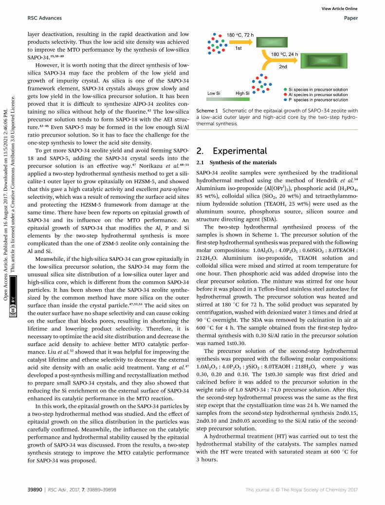
Scheme 1 Schematic of the epitaxial growth of SAPO-34 zeolite witha low-acid outer layer and high-acid core by the two-step hydro-thermal synthesis.
RSC Advances Paper
Ope
n A
cces
s A
rtic
le. P
ublis
hed
on 1
6 A
ugus
t 201
7. D
ownl
oade
d on
11/
5/20
21 2
:46:
06 P
M.
Thi
s ar
ticle
is li
cens
ed u
nder
a C
reat
ive
Com
mon
s A
ttrib
utio
n 3.
0 U
npor
ted
Lic
ence
.View Article Online
layer deactivation, resulting in the rapid deactivation and lowproducts selectivity. Thus the low acid site density was achievedto improve the MTO performance by the synthesis of low-silicaSAPO-34.19,38–40
However, it is worth noting that the direct synthesis of low-silica SAPO-34 may face the problem of the low yield andgrowth of impurity crystal. As silica is one of the SAPO-34framework element, SAPO-34 crystals always grow slowly andgets low yield in the low-silica precursor solution. It has beenproved that it is difficult to synthesize AlPO-34 zeolites con-taining no silica without help of the uorine.42 The low-silicaprecursor solution tends to form SAPO-18 with the AEI struc-ture.43–46 Even SAPO-5 may be formed in the low enough Si/Alratio precursor solution. So it has to face the challenge for theone-step synthesis to lower the acid site density.
To get more SAPO-34 zeolite yield and avoid forming SAPO-18 and SAPO-5, adding the SAPO-34 crystal seeds into theprecursor solution is an effective way.47 Norikazu et al.48–51
applied a two-step hydrothermal synthesis method to get a sili-calite-1 outer layer to grow epitaxially on HZSM-5, and showedthat this gave a high catalytic activity and excellent para-xyleneselectivity, which was a result of removing the surface acid sitesand protecting the HZSM-5 framework from damage at thesame time. There have been few reports on epitaxial growth ofSAPO-34 and its inuence on the MTO performance. Anepitaxial growth of SAPO-34 that modies the Al, P and Sielements by the two-step hydrothermal synthesis is morecomplicated than the one of ZSM-5 zeolite only containing theAl and Si.
Meanwhile, if the high-silica SAPO-34 can grow epitaxially inthe low-silica precursor solution, the SAPO-34 may form theunusual silica site distribution of a low-silica outer layer andhigh-silica core, which is different from the common SAPO-34particles. It has been shown that the SAPO-34 zeolite synthe-sized by the common method have more silica on the outersurface than inside the crystal particle.47,52,53 The acid sites onthe outer surface have no shape selectivity and can cause cokingon the surface that blocks pores, resulting in shortening thelifetime and lowering product selectivity. Therefore, it isnecessary to optimize the acid site distribution and decrease thesurface acid density to achieve better MTO catalytic perfor-mance. Liu et al.52 showed that it was helpful for improving thecatalyst lifetime and ethene selectivity to decrease the externalacid site density with an oxalic acid treatment. Yang et al.47
developed a post-synthesis milling and recrystallization methodto prepare small SAPO-34 crystals, and they also showed thatreducing the Si enrichment on the external surface of SAPO-34enhanced its catalytic performance in the MTO reaction.
In this work, the epitaxial growth on the SAPO-34 particles bya two-step hydrothermal method was studied. And the effect ofepitaxial growth on the silica distribution in the particles wascarefully conrmed. Meanwhile, the inuence on the catalyticperformance and hydrothermal stability caused by the epitaxialgrowth of SAPO-34 was discussed. From the results, a two-stepsynthesis strategy to improve the MTO catalytic performancefor SAPO-34 was proposed.
39890 | RSC Adv., 2017, 7, 39889–39898
2. Experimental2.1 Synthesis of the materials
SAPO-34 zeolite samples were synthesized by the traditionalhydrothermal method using the method of Hendrik et al.54
Aluminium iso-propoxide (Al(OPri)3), phosphoric acid (H3PO4,85 wt%), colloidal silica (SiO2, 20 wt%) and tetraethylammo-nium hydroxide solution (TEAOH, 25 wt%) were used as thealuminum source, phosphorus source, silicon source andstructure directing agent (SDA).
The two-step hydrothermal synthesized process of thesamples is shown in Scheme 1. The precursor solution of therst-step hydrothermal synthesis was prepared with the followingmolar compositions: 1.0Al2O3 : 4.0P2O5 : 0.60SiO2 : 8.0TEAOH :212H2O. Aluminium iso-propoxide, TEAOH solution andcolloidal silica were mixed and stirred at room temperature forone hour. Then phosphoric acid was added dropwise into theclear precursor solution. The mixture was stirred for one hourbefore it was placed in a Teon-lined stainless steel autoclave forhydrothermal growth. The precursor solution was heated andstirred at 180 �C for 72 h. The solid product was separated bycentrifugation, washed with deionized water 3 times and dried at90 �C overnight. The SDA was removed by calcination in air at600 �C for 4 h. The sample obtained from the rst-step hydro-thermal synthesis with 0.30 Si/Al ratio in the precursor solutionwas named 1st0.30.
The precursor solution of the second-step hydrothermalsynthesis was prepared with the following molar compositions:1.0Al2O3 : 4.0P2O5 : ySiO2 : 8.0TEAOH : 218H2O, where y was0.30, 0.20 and 0.10. The 1st0.30 sample was rst dried andcalcined before it was added to the precursor solution in theweight ratio of 1.0 SAPO-34 : 74.0 precursor solution. Aer this,the second-step hydrothermal process was the same as the rststep except that the crystallization time was 24 h. We named thesamples from the second-step hydrothermal synthesis 2nd0.15,2nd0.10 and 2nd0.05 according to the Si/Al ratio of the second-step precursor solution.
A hydrothermal treatment (HT) was carried out to test thehydrothermal stability of the catalysts. The samples namedwith the HT were treated with saturated steam at 600 �C for3 hours.
Fig. 1 SEM images of the samples: (a) 1st0.30; (b) 2nd0.15; (c) 2nd0.10;(d) 2nd0.05.
Paper RSC Advances
Ope
n A
cces
s A
rtic
le. P
ublis
hed
on 1
6 A
ugus
t 201
7. D
ownl
oade
d on
11/
5/20
21 2
:46:
06 P
M.
Thi
s ar
ticle
is li
cens
ed u
nder
a C
reat
ive
Com
mon
s A
ttrib
utio
n 3.
0 U
npor
ted
Lic
ence
.View Article Online
2.2 Characterization
A scanning electron microscope (SEM), Model JEOL JSM-7401,was used to observe the morphology of the samples. The Si, Aland P distributions in the SAPO-34 particles were characterizedby the energy dispersive spectrometer lining (EDS lining) ofa transmission electron microscope (TEM), model JEM-2010.The framework type of the samples was characterized by X-raydiffraction (XRD) with a Bruker D8/Advance instrument (trans-mission mode, Cu Ka radiation, 5� min�1, 5–45�). The total acidsite density was measured by the temperature programmeddesorption of ammonia (TPD-NH3), which was performed ona Quantachrome ChemBET Pulsa. The BET total surface areaand microscopic volume were determined by Ar adsorption anddesorption using a Quantachrom Autosorb iQ2 instrument. Thechemical composition was analyzed by inductively coupledplasma atomic emission spectrometry (ICP-AES) using a SPEC-TRO ARCOS instrument. The surface chemical composition wascharacterized by X-ray photoelectron spectroscopy (XPS) usinga Thermo Fisher 250XI instrument.
The surface acid density was characterized by the TGA-Pymethod. The pyridine is too big to enter the pores of SAPO-34zeolite, so it is only absorbed by the acid sites on the surface.The sample was heated to 500 �C and kept for 1 h in order todrive off water and other impurity gases adsorbed by thesamples. Aer the samples were cooled to 50 �C, pyridine wasinjected and adsorbed for 2 h. To remove the pyridine absorbedphysically, the temperature was increased to 150 �C and held for1 h. Then the temperature was increased from 150 �C to 500 �Cand kept at 500 �C for 1 h. The mass loss aer 150 �C was takenas the amount of pyridine absorbed by the surface acid siteschemically.
2.3 Catalytic experiments
The MTO reaction was tested in a quartz tubular xed bedreactor at 400 �C and atmospheric pressure. 20 mg of thesample mixed with 60 mg quartz (120–180 mesh) was activatedat 400 �C in an Ar gas ow of 20mlmin�1 for 1 h before theMTOreaction. The methanol was fed in by a carrier gas (Ar) usinga saturator containing methanol at room temperature. Theweight hourly space velocity (WHSV) was 4.0 h�1. Another owline of Ar gas was used to keep the methanol feed mole fractionat 4.2%. An online gas chromatograph (Aglient 7890A) was usedto analyze the composition of the gas products. The conversionof methanol and product selectivity were calculated on a carbonbasis. Both methanol and dimethylether (DME) were regardedas reactants.
3. Results and discussion3.1 Morphology, framework type and elemental distribution
The SEM images of the samples are shown in Fig. 1. The 1st0.30sample exhibited 200 nm thick sheet-like morphology (Fig. 1a).The samples grew much bigger but still remained sheet-likeaer the second-step hydrothermal synthesis (Fig. 1b–d).Meanwhile, the surface of these samples was much roughercompared to the 1st0.30 sample. It seems that the 1st0.30
sample acted as the crystal core which continued to grow aer itwas added into the low-silica hydrothermal environment.
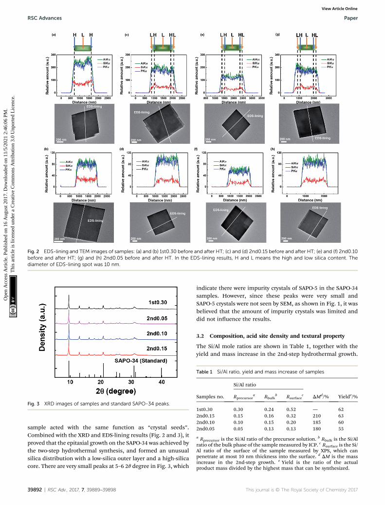
As shown in Fig. 2, the elemental distribution was charac-terized by TEM EDS-lining. The EDS-lining method55–58 not onlyshowed the element distribution in the zeolite, but alsomeasured approximately the thickness of the outer layer grownon the samples epitaxially. The P and Al distribution are kepthighly consistent and indicated the edge and thickness ofa particle. When the P and Al signals begin to increase, it meansthe light spot of the characterization hasmoved onto the edge ofthe particle. Conversely, the P and Al signals will be reducedwhen the light spot for the characterization moves out of theedge of the particle. The P and Al intensities show the thicknessof the particle in the scanning area of EDS-lining.
The Si signal obviously increased on the edge of the particleof 1st0.30 sample, showing the Si enrichment of the externalsurface of the SAPO-34 samples (Fig. 2a and b). This is inagreement with the results in other reports.47,52,53 The P, Al andSi signals of the 1st0.30 sample increased and decreasedsynchronously. However, aer the 2nd-step hydrothermalsynthesis, the Si signal changed in a wider range than the P andAl signals (Fig. 2c–h). This could be explained by that the SAPO-34 crystals were coated by a low-silica outer layer with a thick-ness of about 200 nm. It indicates that a low-silica outer layerhas grown epitaxially onto the 1st-step synthesized SAPO-34 inthe 2nd-step hydrothermal synthesis. The P, Al and Si distri-bution in the SAPO-34 crystals showed few changes aer the HT(Fig. 2d, f and h), which means the low-silica outer layer couldremain stable in the 600 �C saturated steam for 3 hours.
The XRD images of samples and that of reference SAPO-34are shown in Fig. 3. The XRD pattern of the 1st0.30 samplewas in agreement with CHA-type framework, and it remainedunchanged aer the second-step hydrothermal synthesis. Itsuggested that the 2nd-step hydrothermal growth tended to beepitaxial growth on the 1st-step synthesized sample and it keptthe same framework, as opposed to new nucleation and growthindependently of the already-present zeolite. That is, the 1st0.30
Fig. 2 EDS-lining and TEM images of samples: (a) and (b) 1st0.30 before and after HT; (c) and (d) 2nd0.15 before and after HT; (e) and (f) 2nd0.10before and after HT; (g) and (h) 2nd0.05 before and after HT. In the EDS-lining results, H and L means the high and low silica content. Thediameter of EDS-lining spot was 10 nm.
Fig. 3 XRD images of samples and standard SAPO-34 peaks.
Table 1 Si/Al ratio, yield and mass increase of samples
a Rprecursor is the Si/Al ratio of the precursor solution. b Rbulk is the Si/Alratio of the bulk phase of the samplemeasured by ICP. c Rsurface is the Si/Al ratio of the surface of the sample measured by XPS, which canpenetrate at most 10 nm thickness into the surface. d DM is the massincrease in the 2nd-step growth. e Yield is the ratio of the actualproduct mass divided by the highest mass that can be synthesized.
RSC Advances Paper
Ope
n A
cces
s A
rtic
le. P
ublis
hed
on 1
6 A
ugus
t 201
7. D
ownl
oade
d on
11/
5/20
21 2
:46:
06 P
M.
Thi
s ar
ticle
is li
cens
ed u
nder
a C
reat
ive
Com
mon
s A
ttrib
utio
n 3.
0 U
npor
ted
Lic
ence
.View Article Online
sample acted with the same function as “crystal seeds”.Combined with the XRD and EDS-lining results (Fig. 2 and 3), itproved that the epitaxial growth on the SAPO-34 was achieved bythe two-step hydrothermal synthesis, and formed an unusualsilica distribution with a low-silica outer layer and a high-silicacore. There are very small peaks at 5–6 2q degree in Fig. 3, which
39892 | RSC Adv., 2017, 7, 39889–39898
indicate there were impurity crystals of SAPO-5 in the SAPO-34samples. However, since these peaks were very small andSAPO-5 crystals were not seen by SEM, as shown in Fig. 1, it wasbelieved that the amount of impurity crystals was limited anddid not inuence the results.
3.2 Composition, acid site density and textural property
The Si/Al mole ratios are shown in Table 1, together with theyield and mass increase in the 2nd-step hydrothermal growth.
a Atotal is the total acid density calculated from high-temperature area ofTPD-NH3 curve. b Tstrong is the peak temperature in the high-temperature area.
Paper RSC Advances
Ope
n A
cces
s A
rtic
le. P
ublis
hed
on 1
6 A
ugus
t 201
7. D
ownl
oade
d on
11/
5/20
21 2
:46:
06 P
M.
Thi
s ar
ticle
is li
cens
ed u
nder
a C
reat
ive
Com
mon
s A
ttrib
utio
n 3.
0 U
npor
ted
Lic
ence
.View Article Online
Aer the 2nd hydrothermal growth, the mass of two-stepsynthesized samples increased by at least 180%. And whenthe silica content in the 2nd precursor solution became higher,the higher increasing mass and yield were achieved (Table 1),indicating that the high silica environment was conductive tothe growth of SAPO-34 zeolite.
In agreement with the EDS-lining results (Fig. 2a), thesurface Si/Al ratio of 1st0.30 sample was higher than the averagevalue of its bulk phase, showing the surface enrichment of silica(Table 1). About 2 times mass increment of two-step synthesizedsamples led to a decrease of both surface and bulk phase's silicacontent (Table 1). The 2nd-step growth could result in lessenrichment of silica on the surface, and even no difference inthe silica content between the surface and bulk phase when the2nd-step precursor solution had a low enough Si/Al ratio, suchas the 2nd0.05 sample.
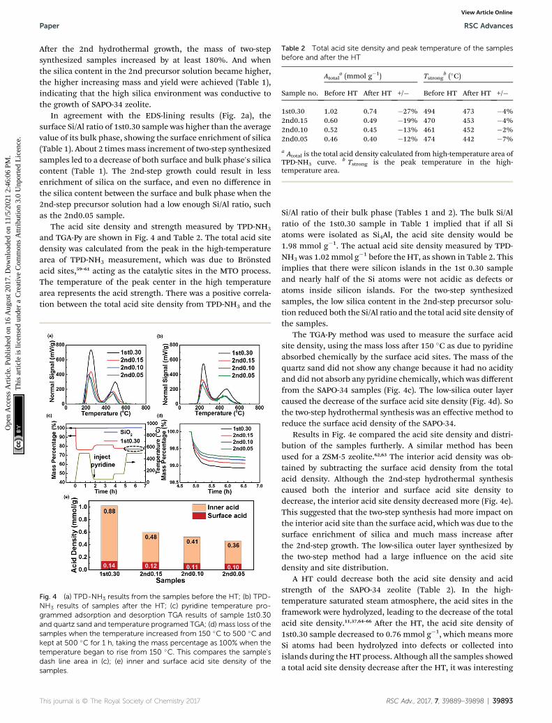
The acid site density and strength measured by TPD-NH3
and TGA-Py are shown in Fig. 4 and Table 2. The total acid sitedensity was calculated from the peak in the high-temperaturearea of TPD-NH3 measurement, which was due to Bronstedacid sites,59–61 acting as the catalytic sites in the MTO process.The temperature of the peak center in the high temperaturearea represents the acid strength. There was a positive correla-tion between the total acid site density from TPD-NH3 and the
Fig. 4 (a) TPD-NH3 results from the samples before the HT; (b) TPD-NH3 results of samples after the HT; (c) pyridine temperature pro-grammed adsorption and desorption TGA results of sample 1st0.30and quartz sand and temperature programed TGA; (d) mass loss of thesamples when the temperature increased from 150 �C to 500 �C andkept at 500 �C for 1 h, taking the mass percentage as 100% when thetemperature began to rise from 150 �C. This compares the sample'sdash line area in (c); (e) inner and surface acid site density of thesamples.
Si/Al ratio of their bulk phase (Tables 1 and 2). The bulk Si/Alratio of the 1st0.30 sample in Table 1 implied that if all Siatoms were isolated as Si4Al, the acid site density would be1.98 mmol g�1. The actual acid site density measured by TPD-NH3 was 1.02mmol g�1 before the HT, as shown in Table 2. Thisimplies that there were silicon islands in the 1st 0.30 sampleand nearly half of the Si atoms were not acidic as defects oratoms inside silicon islands. For the two-step synthesizedsamples, the low silica content in the 2nd-step precursor solu-tion reduced both the Si/Al ratio and the total acid site density ofthe samples.
The TGA-Py method was used to measure the surface acidsite density, using the mass loss aer 150 �C as due to pyridineabsorbed chemically by the surface acid sites. The mass of thequartz sand did not show any change because it had no acidityand did not absorb any pyridine chemically, which was differentfrom the SAPO-34 samples (Fig. 4c). The low-silica outer layercaused the decrease of the surface acid site density (Fig. 4d). Sothe two-step hydrothermal synthesis was an effective method toreduce the surface acid density of the SAPO-34.
Results in Fig. 4e compared the acid site density and distri-bution of the samples furtherly. A similar method has beenused for a ZSM-5 zeolite.62,63 The interior acid density was ob-tained by subtracting the surface acid density from the totalacid density. Although the 2nd-step hydrothermal synthesiscaused both the interior and surface acid site density todecrease, the interior acid site density decreased more (Fig. 4e).This suggested that the two-step synthesis had more impact onthe interior acid site than the surface acid, which was due to thesurface enrichment of silica and much mass increase aerthe 2nd-step growth. The low-silica outer layer synthesized bythe two-step method had a large inuence on the acid sitedensity and site distribution.
A HT could decrease both the acid site density and acidstrength of the SAPO-34 zeolite (Table 2). In the high-temperature saturated steam atmosphere, the acid sites in theframework were hydrolyzed, leading to the decrease of the totalacid site density.11,37,64–66 Aer the HT, the acid site density of1st0.30 sample decreased to 0.76 mmol g�1, which means moreSi atoms had been hydrolyzed into defects or collected intoislands during the HT process. Although all the samples showeda total acid site density decrease aer the HT, it was interesting
a Stotal is the total surface area calculated from the BET equation.b Vmicro is the micropore volume calculated by the Ar isothermaladsorption and desorption curve with the NLDFT equilibrium model.
RSC Advances Paper
Ope
n A
cces
s A
rtic
le. P
ublis
hed
on 1
6 A
ugus
t 201
7. D
ownl
oade
d on
11/
5/20
21 2
:46:
06 P
M.
Thi
s ar
ticle
is li
cens
ed u
nder
a C
reat
ive
Com
mon
s A
ttrib
utio
n 3.
0 U
npor
ted
Lic
ence
.View Article Online
to note that the two-step synthesized samples showed a smallerreduction than the 1st0.30 sample (Table 2 and Fig. 4a and b).And the 2nd0.05 sample with the lowest acid site density lostthe fewest acid site density aer the HT (Table 2). It seemed thatthe SAPO-34 with low acid site density was more stable duringthe HT with respect to the acid site density.
The acid strength of all the samples also decreased aer theHT to a comparable degree (Table 2). As the silica species on theborders of the silica island show the strongest acidity and theywere always rstly hydrolyzed,67,68 the average acid strength ofSAPO-34 showed a decrease aer the HT. In conclusion, thanksto the low acid site density, the two-step synthesized samplesshowed higher hydrothermal stability of the acid sitescompared with the one-step synthesized samples.
The textural properties of the samples before and aer theHT are shown in Table 3. Themicropore volume depends on theamount of zeolite material in the samples, so it representsthe growth completeness of the SAPO-34 zeolites. The reductionof non-framework material can increase the micropore volume.Aer the 2nd-step growth, the textural properties of two-stepsynthesized samples remained almost unchanged, comparedwith the 1st0.30 sample. It implied that crystal epitaxial growthon the SAPO-34 particles in two-step method had little effect onthe textural properties, but great effect on the acid site densityand distribution.
Aer the HT, all the samples had micropore volumeincreases to varying degrees (Table 3). On the one hand, thehigh-temperature saturated steam drives some non-frameworkatom into the framework and these start to recrystallizeduring the HT, resulting in increasing the microporevolume.37,64,69 On the other hand, the hydrolysis of hot steamcan damage the framework of SAPO-34 zeolites, which cause thedecrease of micropore volume.11 In the HT process, the sampleswere more inuenced by the recrystallization than the damage,so the framework of the samples were furtherly improved. Theobvious increase of the 2nd0.10 sample's total surface area andmicropore volume has been noted, which implied a good MTOperformance aer the HT.
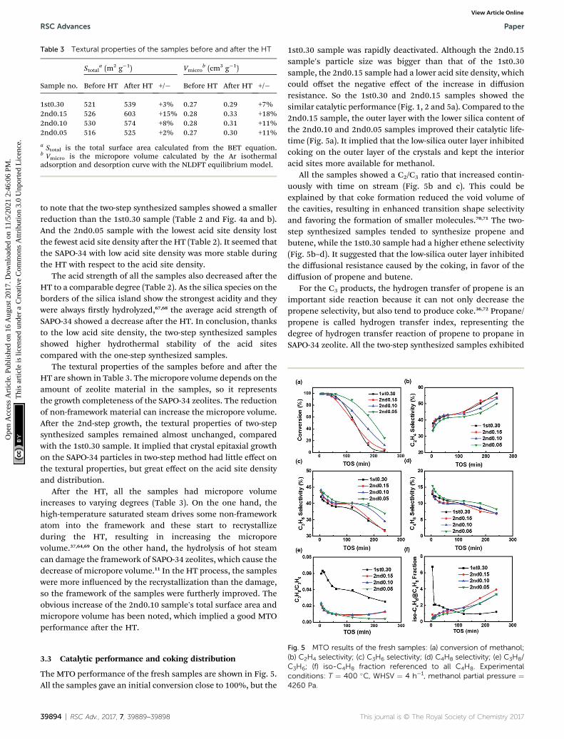
Fig. 5 MTO results of the fresh samples: (a) conversion of methanol;(b) C2H4 selectivity; (c) C3H6 selectivity; (d) C4H8 selectivity; (e) C3H8/C3H6; (f) iso-C4H8 fraction referenced to all C4H8. Experimentalconditions: T ¼ 400 �C, WHSV ¼ 4 h�1, methanol partial pressure ¼4260 Pa.
3.3 Catalytic performance and coking distribution
The MTO performance of the fresh samples are shown in Fig. 5.All the samples gave an initial conversion close to 100%, but the
39894 | RSC Adv., 2017, 7, 39889–39898
1st0.30 sample was rapidly deactivated. Although the 2nd0.15sample's particle size was bigger than that of the 1st0.30sample, the 2nd0.15 sample had a lower acid site density, whichcould offset the negative effect of the increase in diffusionresistance. So the 1st0.30 and 2nd0.15 samples showed thesimilar catalytic performance (Fig. 1, 2 and 5a). Compared to the2nd0.15 sample, the outer layer with the lower silica content ofthe 2nd0.10 and 2nd0.05 samples improved their catalytic life-time (Fig. 5a). It implied that the low-silica outer layer inhibitedcoking on the outer layer of the crystals and kept the interioracid sites more available for methanol.
All the samples showed a C2/C3 ratio that increased contin-uously with time on stream (Fig. 5b and c). This could beexplained by that coke formation reduced the void volume ofthe cavities, resulting in enhanced transition shape selectivityand favoring the formation of smaller molecules.70,71 The two-step synthesized samples tended to synthesize propene andbutene, while the 1st0.30 sample had a higher ethene selectivity(Fig. 5b–d). It suggested that the low-silica outer layer inhibitedthe diffusional resistance caused by the coking, in favor of thediffusion of propene and butene.
For the C3 products, the hydrogen transfer of propene is animportant side reaction because it can not only decrease thepropene selectivity, but also tend to produce coke.36,72 Propane/propene is called hydrogen transfer index, representing thedegree of hydrogen transfer reaction of propene to propane inSAPO-34 zeolite. All the two-step synthesized samples exhibited
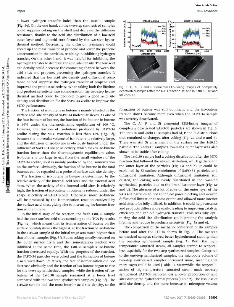
Fig. 6 C, Al, Si and P elemental EDS-lining images of completelydeactivated samples after the MTO reaction: (a) and (b) 1st0.30; (c) and(d) 2nd0.15.
Paper RSC Advances
Ope
n A
cces
s A
rtic
le. P
ublis
hed
on 1
6 A
ugus
t 201
7. D
ownl
oade
d on
11/
5/20
21 2
:46:
06 P
M.
Thi
s ar
ticle
is li
cens
ed u
nder
a C
reat
ive
Com
mon
s A
ttrib
utio
n 3.
0 U
npor
ted
Lic
ence
.View Article Online
a lower hydrogen transfer index than the 1st0.30 sample(Fig. 5e). On the one hand, all the two-step synthesized samplescould suppress coking on the shell and decrease the diffusionresistance, thanks to the acid site distribution of a low-acidouter layer and high-acid core formed by the two-step hydro-thermal method. Decreasing the diffusion resistance couldspeed up the mass transfer of propene and lower the propeneconcentration in the particles, resulting in inhibiting hydrogentransfer. On the other hand, it was helpful for inhibiting thehydrogen transfer to decrease the acid site density. The low acidsite density could decrease the contacting chance between theacid sites and propene, preventing the hydrogen transfer. Itindicated that the low acid site density and diffusional resis-tance helped suppress the hydrogen transfer of propene andimproved the product selectivity. When taking both the lifetimeand product selectivity into consideration, the two-step hydro-thermal method could be deduced to give a good acid sitedensity and distribution for the SAPO-34 zeolite to improve theMTO performance.
The fraction of iso-butene in butene is mainly affected by thesurface acid site density of SAPO-34 molecular sieves. As one ofthe four isomers of butene, the fraction of iso-butene in buteneis 46% under the thermodynamic equilibrium of 400 �C.However, the fraction of iso-butene produced by SAPO-34zeolite during the MTO reaction is less than 10% (Fig. 5f),because the molecular volume of iso-butene is relatively large,and the diffusion of iso-butene is obviously limited under theinuence of SAPO-34 shape selectivity, which makes iso-butenefraction lower than the thermodynamic equilibrium value.Iso-butene is too large to exit from the small windows of theSAPO-34 zeolite, so it is mainly produced by the isomerizationon the surface. Obviously, the fraction of iso-butene in the totalbutenes can be regarded as a probe of surface acid site density.
The fraction of iso-butene in butene is determined by therelative activity of the internal acid sites and the external acidsites. When the activity of the internal acid sites is relativelyhigh, the fraction of iso-butene in butene is reduced under theshape selectivity of SAPO zeolite. Otherwise, more iso-butenewill be produced by the isomerization reaction catalyzed bythe surface acid sites, giving rise to increasing iso-butene frac-tion in the butene.
In the initial stage of the reaction, the fresh 1st0.30 samplehad the most surface acid sites according to the TGA-Py results(Fig. 4e), which meant that its isomerization of butene on thesurface of catalysts was the highest, so the fraction of iso-butenein the 1st0.30 sample of the initial stage was much higher thanthat of other samples (Fig. 5f). But as coking usually occurred onthe outer surface rstly and the isomerization reaction wasinhibited at the same time, the 1st0.30 sample's iso-butenefraction decreased rapidly. With the progress of the reaction,the SAPO-34 particles were coked and the formation of butenealso slowed down. Relatively, the rate of isomerization did notdecrease obviously and the fraction of iso-butene began to risefor the two-step synthesized samples, while the fraction of iso-butene of the 1st0.30 sample remained at a lower levelcompared with the two-step synthesized samples (Fig. 5f). The1st0.30 sample had the most interior acid site density, so the
formation of butene was still dominant and the iso-butenefraction didn't become more even when the SAPO-34 samplewas severely deactivated.
The C, Al, P and Si elemental EDS-lining images ofcompletely deactivated SAPO-34 particles are shown in Fig. 6.The 1st0.30 and 2nd0.15 samples had Al, P and Si distributionsthat remained unchanged aer coking (Fig. 2a and c and 6).There was still Si enrichment of the surface on the 1st0.30particle. The 2nd0.15 sample's low-silica outer layer was alsoshown to be stable aer coking.
The 1st0.30 sample had a coking distribution aer the MTOreaction that followed the silica distribution, which gathered onthe outer layer of the particles (Fig. 6a and b). It could beexplained by Si surface enrichment of SAPO-34 particles anddiffusional limitation. Although diffusional limitation stillexisted, the coking was evenly distributed in the two-stepsynthesized particles due to the low-silica outer layer (Fig. 6cand d). The absence of a lot of coke on the outer layer of theSAPO-34 particles helped to inhibit pores blocking and weakendiffusional limitation to some extent, and allowedmore interioracid sites to be fully utilized. In addition, it could help reactantsand products diffuse more easily, leading to improving catalyticefficiency and inhibit hydrogen transfer. This was why opti-mizing the acid site distribution could prolong the catalyticlifetime and reduce byproducts selectivity (Fig. 5a and e).
The comparison of the methanol conversion of the samplesbefore and aer the HT is shown in Fig. 7. The two-stepsynthesized samples showed better hydrothermal stability thanthe one-step synthesized sample (Fig. 7). With the high-temperature saturated steam, all samples started to recrystal-lize, especially for the two-step synthesized samples. Comparedto the one-step synthesized samples, the micropore volume oftwo-step synthesized samples increased more, meaning thatmore cages could be used (Table 3). Meanwhile, the recrystalli-zation of high-temperature saturated steam made two-stepsynthesized SAPO-34 samples loss a lower proportion of acidsites during the hydrothermal process (Table 2). The less loss ofacid site density and the more increase in micropore volume
Fig. 7 Methanol conversion of the samples before and after the HT.
RSC Advances Paper
Ope
n A
cces
s A
rtic
le. P
ublis
hed
on 1
6 A
ugus
t 201
7. D
ownl
oade
d on
11/
5/20
21 2
:46:
06 P
M.
Thi
s ar
ticle
is li
cens
ed u
nder
a C
reat
ive
Com
mon
s A
ttrib
utio
n 3.
0 U
npor
ted
Lic
ence
.View Article Online
ensure the better hydrothermal stability of the two-step synthe-sized samples relative to the one-step synthesized samples.
It was interesting to note that the 2nd0.15 sample had itslifetime prolonged aer the HT, which was different from theother samples. Its micropore volume increased 18% duringthe hydrothermal process (Table 2). The obvious increase of itsmicropore volume was helpful for catalysis, despite the modestreduction of its acid site density. Thus, the two-step hydro-thermal synthesis showed good hydrothermal stability, whichwas important for the MTO industrial application.
As a model study, this work not only proves the feasibility ofepitaxial growth of a low-silica shell on the high-silica SAPO-34,but also shows the better MTO catalytic performance andhydrothermal stability, compared to the common one-stepsynthesized sample. The two-step synthesized samples achievehigh molecular sieves yield in the synthesis, and remain theCHA structure, preventing forming other impurity crystals. Itwill be a great advantage if one-step synthesized low-silicasample is taken into comparison. Meanwhile, the two-stepsynthesized samples have an unusual acid distribution ofhigh-acid core and low-acid outer layer. The low-acid outer layerinhibits coking on the outer layer and weakens diffusionallimitation, which can cause better utilization of interior acidsites and prolong the catalytic lifetime. In addition, a properacid site density and distribution formed by the two-stepsynthesized method can help suppress the hydrogen transferof propene and improves the product selectivity.
4. Conclusions
A low-silica SAPO-34 zeolite, that is, a low acid site density SAPO-34 zeolite, shows better MTO performance, but it suffers theproblem of low yield and impure crystal when synthesized bya one-step hydrothermal method. This work demonstrateda practical two-step hydrothermal synthesis strategy that gaveSAPO-34 zeolite with the acid site distribution of a high-silicacore and a low-silica outer layer. EDS-lining conrmed thata low-silica outer layer was epitaxially grown on a high-silicacore, and measured the thickness of the low-silica outer layer
39896 | RSC Adv., 2017, 7, 39889–39898
as 200 nm. During the second-step hydrothermal synthesis ina low-silica precursor solution, the high-silica core acted ascrystal seed for the growth of the low-silica outer layer and alsoinhibited the formation of impure crystal.
Diffusion resistance has a signicant impact on the activityand product selectivity in the MTO reaction. The core–shellSAPO-34 zeolite here showed a longer catalyst lifetime, becauseit beneted from that most of the catalytic reaction occurred inthe low acid site outer layer. Unlike the one-step synthesizedhigh-silica sample, the low acid site outer layer of the two-stepsynthesized samples showed inhibited coking and reduceddiffusion limitation, resulting in increased lifetime. Aera hydrothermal treatment, the two-step synthesized samplesshowed less reduction of acid site density and a larger increasein the micropore volume than the one-step synthesized sample,that is, they showed better hydrothermal stability than the one-step synthesized sample.
To study the epitaxial growth by EDS-lining, relatively largeparticles were formed in the rst-step growth and used as coreseeds in the second-step growth. It was deduced that forindustrial use, by using a smaller high-silica SAPO-34 zeolite as“crystal seed” and with the thickness of the low-silica outer layeroptimized, even better MTO performance will be achieved.
Conflicts of interest
There are no conicts of interest to declare.
Acknowledgements
We thank the National Natural Science Foundation of China(21173125) and the National High Technology Research andDevelopment Program of China (863 Program, 2012AA051001)for their nancial support for this study.
References
1 M. Stocker and J. Weitkamp,Microporous Mesoporous Mater.,1999, 29, 1.
2 M. Stocker, Microporous Mesoporous Mater., 1999, 29, 3–48.3 U. Olsbye, S. Svelle, M. Bjorgen, P. Beato, T. V. W. Janssens,F. Joensen, S. Bordiga and K. P. Lillerud, Angew. Chem., Int.Ed., 2012, 51, 5810–5831.
4 I. M. Dahl and S. Kolboe, J. Catal., 1996, 161, 304–309.5 I. M. Dahl and S. Kolboe, J. Catal., 1994, 149, 458–464.6 I. M. Dahl and S. Kolboe, Catal. Lett., 1993, 20, 329–336.7 M. Bjorgen, S. Svelle, F. Joensen, J. Nerlov, S. Kolboe,F. Bonino, L. Palumbo, S. Bordiga and U. Olsbye, J. Catal.,2007, 249, 195–207.
8 S. Svelle, F. Joensen, J. Nerlov, U. Olsbye, K.-P. Lillerud,S. Kolboe and M. Bjorgen, J. Am. Chem. Soc., 2006, 128,14770–14771.
9 H. Yamazaki, H. Shima, H. Imai, T. Yokoi, T. Tatsumi andJ. N. Kondo, J. Phys. Chem. C, 2012, 116, 24091–24097.
10 S. Ilias and A. Bhan, J. Catal., 2012, 290, 186–192.11 Z. Li, J. Martinez-Triguero, P. Concepcion, J. Yu and
A. Corma, Phys. Chem. Chem. Phys., 2013, 15, 14670–14680.
12 W. Dai, G. Wu, L. Li, N. Guan and M. Hunger, ACS Catal.,2013, 3, 588–596.
13 X. Chen, D. Xi, Q. Sun, N. Wang, Z. Dai, D. Fan, V. Valtchevand J. Yu, Microporous Mesoporous Mater., 2016, 234, 401–408.
14 Q. Sun, N. Wang, R. Bai, X. Chen and J. Yu, J. Mater. Chem. A,2016, 4, 14978–14982.
15 B. Gao, M. Yang, Y. Qiao, J. Li, X. Xiang, P. Wu, Y. Wei, S. Xu,P. Tian and Z. Liu, Catal. Sci. Technol., 2016, 6, 7569–7578.
16 J. F. Haw and D. M. Marcus, Top. Catal., 2005, 34, 41–48.17 S.-G. Lee, H.-S. Kim, Y.-H. Kim, E.-J. Kang, D.-H. Lee and
C.-S. Park, J. Ind. Eng. Chem., 2014, 20, 61–67.18 J. Liang, H. Y. Li, S. Zhao, W. G. Guo, R. H. Wang and
M. L. Ying, Appl. Catal., 1990, 64, 31–40.19 A. Izadbakhsh, F. Farhadi, F. Khorasheh, S. Sahebdelfar,
M. Asadi and Y. Z. Feng, Appl. Catal., A, 2009, 364, 48–56.20 D. Chen, K. Moljord, T. Fuglerud and A. Holmen,
Microporous Mesoporous Mater., 1999, 29, 191–203.21 N. Nishiyama, M. Kawaguchi, Y. Hirota, D. Van Vu,
Y. Egashira and K. Ueyama, Appl. Catal., A, 2009, 362, 193–199.
22 S. Lin, J. Li, R. P. Sharma, J. Yu and R. Xu, Top. Catal., 2010,53, 1304–1310.
23 Q. Sun, Y. Ma, N. Wang, X. Li, D. Xi, J. Xu, F. Deng,K. B. Yoon, P. Oleynikov, O. Terasaki and J. Yu, J. Mater.Chem. A, 2014, 2, 17828–17839.
24 G. Yang, Y. Wei, S. Xu, J. Chen, J. Li, Z. Li, J. Yu and R. Xu, J.Phys. Chem. C, 2013, 117, 8214–8222.
25 K. Y. Lee, H.-J. Chae, S.-Y. Jeong and G. Seo, Appl. Catal., A,2009, 369, 60–66.
26 D. Xi, Q. Sun, J. Xu, M. Cho, H. S. Cho, S. Asahina, Y. Li,F. Deng, O. Terasaki and J. Yu, J. Mater. Chem. A, 2014, 2,17994–18004.
27 J. Zhu, Y. Cui, Y. Wang and F. Wei, Chem. Commun., 2009,3282–3284.
28 H. Yang, Z. Liu, H. Gao and Z. Xie, J. Mater. Chem., 2010, 20,3227–3231.
29 Y. Li, Y. Huang, J. Guo, M. Zhang, D. Wang, F. Wei andY. Wang, Catal. Today, 2014, 233, 2–7.
30 F. Schmidt, S. Paasch, E. Brunner and S. Kaskel,MicroporousMesoporous Mater., 2012, 164, 214–221.
31 A. Z. Varzaneh, J. Towghi, S. Sahebdelfar and H. Bahrami, J.Anal. Appl. Pyrolysis, 2016, 121, 11–23.
32 A. Z. Varzaneh, J. Towghi and S. Sahebdelfar, MicroporousMesoporous Mater., 2016, 236, 1–12.
33 Q. Sun, N. Wang, G. Guo, X. Chen and J. Yu, J. Mater. Chem.A, 2015, 3, 19783–19789.
34 Q. Sun, N. Wang, D. Xi, M. Yang and J. Yu, Chem. Commun.,2014, 50, 6502–6505.
35 X. Chen, A. Vicente, Z. Qin, V. Ruaux, J.-P. Gilson andV. Valtchev, Chem. Commun., 2016, 52, 3512–3515.
36 F. D. P. Mees, P. Van Der Voort, P. Cool, L. R. M. Martens,M. J. G. Janssen, A. A. Verberckmoes, G. J. Kennedy,R. B. Hall, K. Wang and E. F. Vansant, J. Phys. Chem. B,2003, 107, 3161–3167.
37 Z. Li, J. Martinez-Triguero, J. Yu and A. Corma, J. Catal.,2015, 329, 379–388.