44
1 Satcomm with Internal Data Logger Manual for Internal Data Logger 5/8/2013
1
Satcomm with Internal Data Logger
Manual for Internal Data Logger
5/8/2013

2
Contents Section List: Page
1 INTRODUCTION……………………………………3
2 INSTALLATION……………………………………..13
3 OPERATION ………………………………………..17
4 MAINTENANCE AND TROUBLESHOOTING…..35
5 APPENDICES……………………………………….38
3
Introduction ________________________________________________________ Safety and Equipment Protection Information Before performing any procedures in this manual, please read all applicable WARNINGS and CAUTIONS in this section. Power sources, including batteries, can be a particular hazard to the user. The SATCOMM INTERNAL LOGGER instruction manual and Satcomm(LoggerSet) GUI interface is organized so that the experienced user can operate the instrument with the least amount of reading. WARNING! ELECTRICAL POWER CAN RESULT IN DEATH, PERSONAL INJURY OR CAN CAUSE DAMAGE TO EQUIPMENT. If the instrument is driven by an external power source, disconnect the instrument from that power source before attempting any repairs. WARNING! BATTERIES ARE DANGEROUS. IF HANDLED IMPROPERLY, THEY CAN RESULT IN DEATH, PERSONAL INJURY OR CAN CAUSE DAMAGE TO EQUIPMENT. Batteries can be hazardous when misused, mishandled, or disposed of improperly. Batteries contain potential energy, even when partially discharged. WARNING! ELECTRICAL SHOCK CAN RESULT IN DEATH OR PERSONAL INJURY. Use extreme caution when handling cables, connectors, or terminals; they may yield hazardous currents if inadvertently brought into contact with conductive materials, including water and the human body. CAUTION! Be aware of protective measures against environmentally caused electric current surges. In addition to the previous warnings and cautions, the following safety activities should be carefully observed. Children, Adolescents NEVER give batteries to young people who may not be aware of the hazards associated with batteries and their improper use or disposal. Jewelry, Watches, Metal Tags To avoid severe burns, NEVER wear rings, necklaces, metal watch bands, bracelets, or metal identification tags near exposed battery terminals. Heat & Fire.

4
NEVER dispose of batteries in fire or locate them in excessively heated spaces. Observe the temperature limit listed in the instrument specifications. Charging NEVER charge “dry” cells or lithium batteries that are not designed to be charged. NEVER charge rechargeable batteries at currents higher than recommended ratings. NEVER recharge a frozen battery. Thaw it completely at room temperature before connecting charger. Unvented Container NEVER store or charge batteries in a gas-tight container. Doing so may lead to pressure buildup and explosive concentrations of hydrogen. Short circuits NEVER short circuit batteries. High current flow may cause internal battery heating and/or explosion. Damaged Batteries Personal injury may result from contact with hazardous materials from a damaged or open battery. NEVER attempt to open a battery enclosure. Wear appropriate protective clothing and handle damaged batteries carefully. Disposal ALWAYS dispose of batteries in a responsible manner. Observe all applicable federal, state, and local regulations for disposal of the specific type of battery involved. NOTICE Stevens makes no claims as to the immunity of its equipment against lightning strikes, either direct or nearby. The following statement is required by the Federal Communications Commission: WARNING - This equipment generates, uses, and can radiate radio frequency energy with the optional Wi-Fi module and, if not installed in accordance with the instructions manual, may cause interference to radio communications. It has been tested and found to comply with the limits for a Class A computing device pursuant to Subpart J of Part 15 of FCC Rules, which are designed to provide reasonable protection against such interference when operated in a commercial environment. USER INFORMATION Stevens makes no warranty as to the information furnished in these instructions and the reader assumes all risk in the use thereof. No liability is assumed for damages resulting from the use of these instructions. We reserve the right to make changes to products and/or publications without prior notice.

5
SATCOMM INTERNAL LOGGER Equipment and Parts Thank you for purchasing a SATCOMM INEGRATED LOGGER from Stevens Water Monitoring Systems Inc. (Stevens). Please unpack and examine the SATCOMM INTERNAL LOGGER parts carefully. If there is any apparent shipping damage, contact the shipper immediately. Also, contact the Stevens for replacement of the unit. In this package (see Figure 1.1) you will find the following parts: 1. SATCOMM INTERNAL LOGGER unit in an anodized aluminum enclosure with front/ back
panels accessible to all standard signal connections. 2. One power cable 3. USB A to B cable 4. Two Fast-on® terminal connectors and two spade lugs for battery power connection 5. Breakout Box for sensor connection (Pulse, 4 Analog, and SDI-12) 6. One removable SD memory card (2 gigabyte)
System Requirements External power: either a 12V battery with at least 3 amp hours or a standard AC to DC power source. 1. A RS232 serial cable, USB cable or Stevens’ Shark™ Bluetooth RS232/RS485 adapter (a
“wireless serial cable”) for programming / configuration using a PDA or computer 2. A PDA, PC or laptop computer equipped with:
a. RS-232 serial port, USB-to-serial port adapter, or USB port b. Stevens’ Satcomm(LoggerSet) loaded on computer. These programs can also be
downloaded from the CD or on-line at:
http://www.stevenswater.com/software/downloads.aspx
3. Sensors using pulse, analog (5 V or 4-20mA), and SDI-12 output
Useful Tools and Peripherals Small standard 3.0 x 100mm screwdriver for sensor and power connections Philips screwdriver for mounting screws
General Description The SATCOMM INTERNAL LOGGER is a programmable data logger instrument in a compact, rugged design. Designed using the latest Digital Signal Processing (DSP) technology with multiple sensor inputs, the SATCOMM INTERNAL LOGGER will meet a diversity of data acquisition, processing, control and communication application. The SATCOMM INTERNAL LOGGER accepts 1 pulse count input, 4 analog inputs (0 to 5VDC or 4-20mA), SDI-12 signal input. The SDI-12 I/O provides for 12 SDI-12 channels with 9 parameters per channel. Each channel can have a separate recording interval for logging. With 2 gigabytes of internal memory, the SATCOMM INTERNAL LOGGER stores over 1,000,000,000 readings in floating point format, giving a wide range of sensor scaling capabilities. Alarm outputs can be programmed for each sensor input channel. User can setup 1 out of 9 parameters for each SDI-12 sensor on alarm/alarm output.

6
On board, 5 and 12 VDC continuous power and 12 and 24 VDC switched power is provided. Standard RS-232 and USB ports are provided for communications, setup, and downloading of stored data. Programming / configuration data transfer rates is set at 38.4K BAUD. Reporting data transfer for telemetry purposes is user programmable between 1200 to 115,200 BAUD. Data format is 8 data bits, 1 stop bit, and no parity. The SATCOMM INTERNAL LOGGER provides for programmable flow measurements with standard flumes or weirs. The SATCOMM INTERNAL LOGGER provides for one control voltage output. SATCOMM INTERNAL LOGGER -
SD CARD: External card slot for SD card. INTERNAL LOGGER I/O: connection from Sensor Breakout Box to logger. TOUCH SCREEN: RS232 Port (Comm 1) DCP COMMAND RECEIVER: RS Port (Comm 2) for future secondary telemetry option USB: USB type B connection from Satcomm to PC. EXTERNAL LOGGER: for connecting 3rd party data logger.
Additional Options Available Stevens Touch Screen Display Enclosure
Basic Principles of Operation The SATCOMM INTERNAL LOGGER is designed for long-term, low power operation, unattended, in remote areas. Most sensors are powered down as well (with the exception of SDI-12 sensors, which require a low standby operating power). At a specified time, usually corresponding to initiation of a recording interval or a report mode, the logger will wake up to perform the necessary operations, and then return to the sleep mode. Recording of sensor readings is on a time interval basis. Different sensors can have different logging intervals. Report transmissions can be on an interval basis, or by external control. Primary applications for the SATCOMM INTERNAL LOGGER are those requiring GOES telemetry.
7
Indicator light (labeled “LOGGER ACTIVITY” ) Power LED to indicating the following:
INPUT / OUTPUT TERMINAL CONNECTIONS There are several available connections to the SATCOMM INTERNAL LOGGER System: Power cable: At the location labeled Power. Signal input(s): 6-pin external terminal strips for the following sensors types (if applicable):
Pulse Input: At connector location Pulse. Analog 1-4: At connector locations Ch1, Ch2, Ch3, Ch4, Either 0-5VDC or 4-20mA,
switched. SDI-12: At connector location +12/SW and SDI12. Control output: 0 – 5 VDC at the Vout.
Light Condition Meaning of Light Condition Solid light on Connection has been established with
Satcomm(LoggerSet). Light says solid until you upload configuration or disconnect. SATCOMM INTERNAL LOGGER will flash once a second after the configuration is uploaded. After upload the light does not remain solid even if connected.
Solid light on for approximately 1 second Power to the SATCOMM INTERNAL LOGGER has been established
Flash (every sec) while connect to Satcomm(LoggerSet)
Light says solid until you upload configuration or disconnect. SATCOMM INTERNAL LOGGER will flash once a second after the configuration is uploaded.
Flash (every sec) when not connected Logger in normal logging operation mode based on configuration programming
Flash-Solid (while transferring)-Flash The logger transferring data from internal memory to external SD card (DON’T REMOVE THE SD CARD DURING THIS PROCESS) transfer
No Flash Processing and doing some internal processing or calculations and does not want to be interrupted. This should last no more than 20 seconds before starting to flash once a second. For example, a large number of sensors connected will cause such delays in one second flashing. DO NOT DISCONNECT POWER IF NOT FLASHING. IF NO FLASHING, CONNECT WITH SATCOMMSET TO DIAGNOSE SITUATION.
8
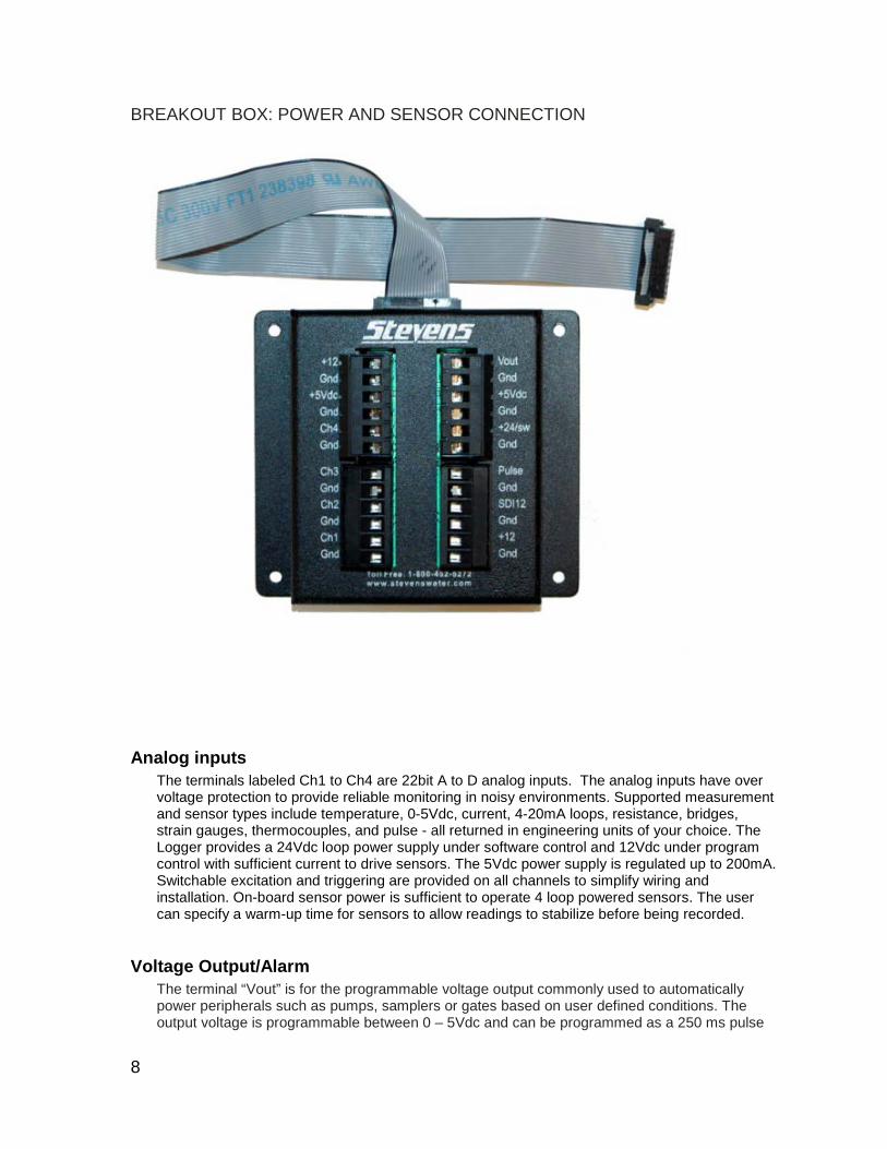
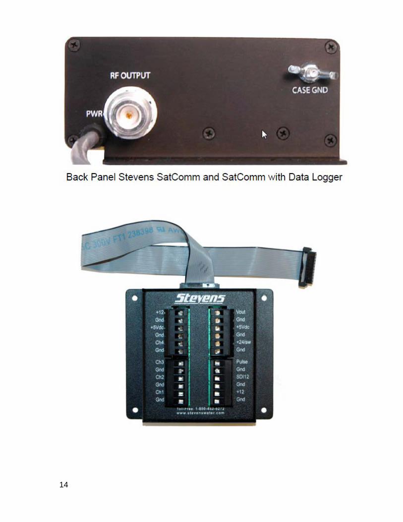
BREAKOUT BOX: POWER AND SENSOR CONNECTION
Analog inputs The terminals labeled Ch1 to Ch4 are 22bit A to D analog inputs. The analog inputs have over voltage protection to provide reliable monitoring in noisy environments. Supported measurement and sensor types include temperature, 0-5Vdc, current, 4-20mA loops, resistance, bridges, strain gauges, thermocouples, and pulse - all returned in engineering units of your choice. The Logger provides a 24Vdc loop power supply under software control and 12Vdc under program control with sufficient current to drive sensors. The 5Vdc power supply is regulated up to 200mA. Switchable excitation and triggering are provided on all channels to simplify wiring and installation. On-board sensor power is sufficient to operate 4 loop powered sensors. The user can specify a warm-up time for sensors to allow readings to stabilize before being recorded.
Voltage Output/Alarm The terminal “Vout” is for the programmable voltage output commonly used to automatically power peripherals such as pumps, samplers or gates based on user defined conditions. The output voltage is programmable between 0 – 5Vdc and can be programmed as a 250 ms pulse
9
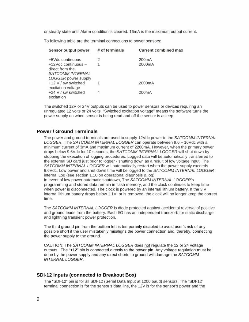
or steady state until Alarm condition is cleared. 16mA is the maximum output current. To following table are the terminal connections to power sensors:
Sensor output power
# of terminals Current combined max
+5Vdc continuous 2 200mA +12Vdc continuous – direct from the SATCOMM INTERNAL LOGGER power supply
1 2000mA
+12 V / sw switched excitation voltage
1 2000mA
+24 V / sw switched excitation
4 200mA
The switched 12V or 24V outputs can be used to power sensors or devices requiring an unregulated 12 volts or 24 volts. “Switched excitation voltage” means the software turns the power supply on when sensor is being read and off the sensor is asleep.
Power / Ground Terminals The power and ground terminals are used to supply 12Vdc power to the SATCOMM INTERNAL LOGGER. The SATCOMM INTERNAL LOGGER can operate between 9.6 – 16Vdc with a minimum current of 3mA and maximum current of 2200mA. However, when the primary power drops below 9.6Vdc for 10 seconds, the SATCOMM INTERNAL LOGGER will shut down by stopping the execution of logging procedures. Logged data will be automatically transferred to the external SD card just prior to logger - shutting down as a result of low voltage input. The SATCOMM INTERNAL LOGGER will automatically restart when the power supply exceeds 9.6Vdc. Low power and shut down time will be logged to the SATCOMM INTERNAL LOGGER internal Log (see section 1.10 on operational diagnosis & log) In event of low power automatic shutdown, The SATCOMM INTERNAL LOGGER’s programming and stored data remain in flash memory, and the clock continues to keep time when power is disconnected. The clock is powered by an internal lithium battery. If the 3 V internal lithium battery drops below 1.1V, or is removed, the clock will no longer keep the correct time.
The SATCOMM INTERNAL LOGGER is diode protected against accidental reversal of positive and ground leads from the battery. Each I/O has an independent transzorb for static discharge and lightning transient power protection. The third ground pin from the bottom left is temporarily disabled to avoid user’s risk of any possible short if the user mistakenly misaligns the power connection and, thereby, connecting the power supply to the ground. CAUTION: The SATCOMM INTERNAL LOGGER does not regulate the 12 or 24 voltage outputs. The “+12” pin is connected directly to the power pin. Any voltage regulation must be done by the power supply and any direct shorts to ground will damage the SATCOMM INTERNAL LOGGER.
SDI-12 Inputs (connected to Breakout Box) The “SDI-12” pin is for all SDI-12 (Serial Data Input at 1200 baud) sensors. The “SDI-12” terminal connection is for the sensor’s data line, the 12V is for the sensor’s power and the
10
ground is for the sensor’s ground wire. The SATCOMM INTERNAL LOGGER is programmable to accept up to 12 SDI-12 sensors with up to 9 parameters for each sensor. The +12V SDI-12 power supply is not switched or regulated. The “+12” terminal is connected directly to the “power” in terminal. Any voltage regulation must be done by the sensor or external power supply and any direct shorts to ground will damage the SATCOMM INTERNAL LOGGER.
Pulse The “Pulse” pin is for the pulse counter input, such as a tipping bucket rain gauge. The pulse input can be programmed for switch closure (see Section 3.2.5). Pulse sensors can be logged in an accumulate mode or count mode. Maximum pulse input rate is 2 times per second or 2Hz.
I/O Communications Ports Three (3) RS232 serial port connections One (1) USB downstream style B connection
RS232 Connection
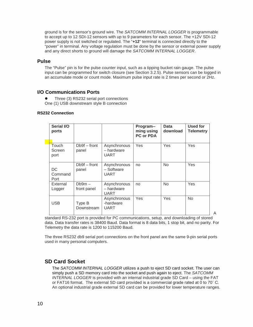
A standard RS-232 port is provided for PC communications, setup, and downloading of stored data. Data transfer rates is 38400 Baud. Data format is 8 data bits, 1 stop bit, and no parity. For Telemetry the data rate is 1200 to 115200 Baud. The three RS232 db9 serial port connections on the front panel are the same 9-pin serial ports used in many personal computers.
SD Card Socket The SATCOMM INTERNAL LOGGER utilizes a push to eject SD card socket. The user can simply push a SD memory card into the socket and push again to eject. The SATCOMM INTERNAL LOGGER is provided with an internal industrial grade SD Card – using the FAT or FAT16 format. The external SD card provided is a commercial grade rated at 0 to 70˚ C. An optional industrial grade external SD card can be provided for lower temperature ranges.
Serial I/O ports
Program--ming using PC or PDA
Data download
Used for Telemetry
Touch Screen port
Db9f – front panel
Asynchronous – hardware UART
Yes Yes Yes
DC Command Port
Db9f – front panel
Asynchronous – Software UART
no No Yes
External Logger
Db9m – front panel
Asynchronous – hardware UART
no No Yes
USB
Type B Downstream
Asynchronous -hardware UART
Yes Yes No
11
Memory The SATCOMM INTERNAL LOGGER contains both volatile and non-volatile memory subsystems.
Volatile memory For storage of information needed quickly, such as scratch pads used in calculations, the SATCOMM INTERNAL LOGGER has static RAM internal in each of its microprocessor chips.
Non-volatile memory The SATCOMM INTERNAL LOGGER programming and configuration file programmed using Satcomm(LoggerSet) are store in the microprocessor chip’s flash memory. In addition to the externally accessible 2 Gigabyte SD card, the SATCOMM INTERNAL LOGGER has an internal, permanently secured SD card that stores up to 2 Gigabytes of logged data. This internal SD card contains all the logged data until it is erased. If the data file exceeds 2,000 megabytes, the SATCOMM INTERNAL LOGGER will overwrite the oldest data. The SATCOMM INTERNAL LOGGER automatically transfers data it has collected since the top of the hour from the internal SD card to the external SD card. This data is stored in the file xxxxxxxB.csv on the external SD card. B is appending to the last time transfer. The xxxxxxx is the last seven characters of the SATCOMM INTERNAL LOGGER’s MAC address. The file xxxxxxxA.csv is created when the data is manually transferred (See MAC ADDRESS Section ) from the internal SD to external SD card using Satcomm(LoggerSet). If there is no external SD Card, or the SD Card is not clicked into place, the SATCOMM INTERNAL LOGGER will recognize the external SD Card is missing and will not attempt to write data to this external memory port.
Internal diagnostic – not currently fully operational The SATCOMM INTERNAL LOGGER performs internal tests periodically on its hardware and its firmware. If something goes wrong it will write what it thinks the problem is to a diagnostic file on the internal SD card. If something catastrophic goes wrong such as a low input power supply, the SATCOMM INTERNAL LOGGER will write this to the diagnostic file and quit flashing the once a second “heartbeat” LED located on the front panel under the text “Test”.
12
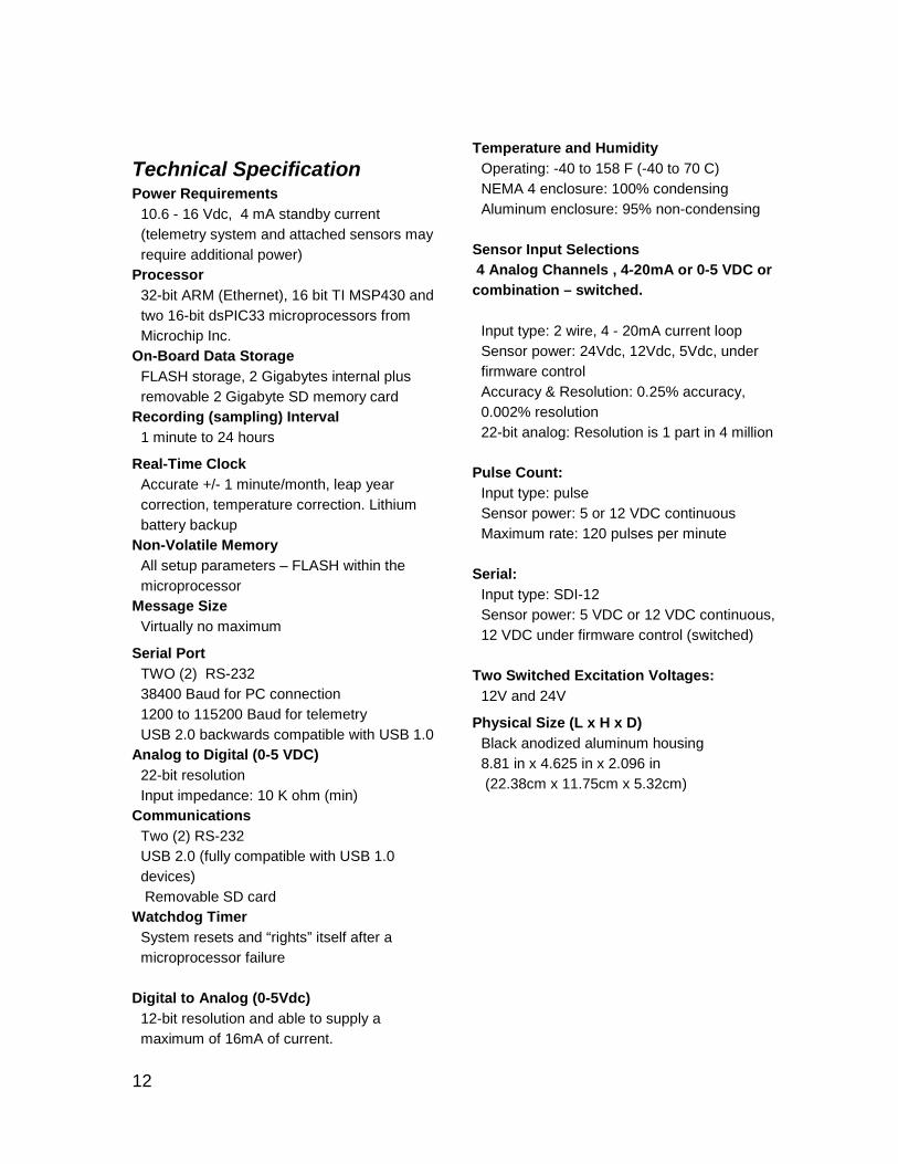
Technical Specification Power Requirements
10.6 - 16 Vdc, 4 mA standby current (telemetry system and attached sensors may require additional power)
Processor 32-bit ARM (Ethernet), 16 bit TI MSP430 and two 16-bit dsPIC33 microprocessors from Microchip Inc.
On-Board Data Storage FLASH storage, 2 Gigabytes internal plus removable 2 Gigabyte SD memory card
Recording (sampling) Interval 1 minute to 24 hours
Real-Time Clock Accurate +/- 1 minute/month, leap year correction, temperature correction. Lithium battery backup
Non-Volatile Memory All setup parameters – FLASH within the microprocessor
Message Size Virtually no maximum
Serial Port TWO (2) RS-232 38400 Baud for PC connection 1200 to 115200 Baud for telemetry USB 2.0 backwards compatible with USB 1.0
Analog to Digital (0-5 VDC) 22-bit resolution Input impedance: 10 K ohm (min)
Communications Two (2) RS-232 USB 2.0 (fully compatible with USB 1.0 devices) Removable SD card
Watchdog Timer System resets and “rights” itself after a microprocessor failure
Digital to Analog (0-5Vdc)
12-bit resolution and able to supply a maximum of 16mA of current.
Temperature and Humidity Operating: -40 to 158 F (-40 to 70 C) NEMA 4 enclosure: 100% condensing Aluminum enclosure: 95% non-condensing
Sensor Input Selections 4 Analog Channels , 4-20mA or 0-5 VDC or combination – switched.
Input type: 2 wire, 4 - 20mA current loop Sensor power: 24Vdc, 12Vdc, 5Vdc, under firmware control Accuracy & Resolution: 0.25% accuracy, 0.002% resolution 22-bit analog: Resolution is 1 part in 4 million
Pulse Count: Input type: pulse Sensor power: 5 or 12 VDC continuous Maximum rate: 120 pulses per minute
Serial: Input type: SDI-12 Sensor power: 5 VDC or 12 VDC continuous, 12 VDC under firmware control (switched)
Two Switched Excitation Voltages:
12V and 24V
Physical Size (L x H x D) Black anodized aluminum housing 8.81 in x 4.625 in x 2.096 in (22.38cm x 11.75cm x 5.32cm)
13
Installation ________________________________________________________
Mechanical Installation
The unit needs to be installed in a NEMA-4 compliant enclosure (water-tight, dust-tight, and corrosion-resistant), or in an area protected from direct weather contact. This can be achieved by mounting the equipment in an existing gage house or other suitable structure. It is recommended that such enclosures be of a light color to reflect solar radiation to reduce internal enclosure temperatures. 1. Unpack and examine the SATCOMM INTERNAL LOGGER carefully. If there is any apparent
shipping damage, contact the shipper immediately. Also contact the factory for replacement of the unit.
2. There are four mounting holes for attachment to a wall or panel. The four holes also line up with
pre-drilled holes in Stevens’ NEMA-4 enclosure designed for the SATCOMM INTERNAL LOGGER
Position the logger so the power, sensor and signal cables can be connected to the power source, input device, and telemetry device, if used. Make sure that the enclosure you have selected provides enough headroom for the cables that will attach to the face of the logger.
Electrical Installation
Connecting Power
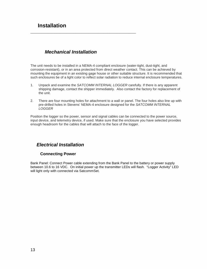
Bank Panel: Connect Power cable extending from the Bank Panel to the battery or power supply between 10.6 to 16 VDC. On initial power up the transmitter LEDs will flash. “Logger Activity” LED will light only with connected via SatcommSet.
14
15
Sensor Connection Attach sensor cable(s) to SATCOMM INTERNAL LOGGER as described below using the terminal connections on the breakout box provided, or refer to your sensor instructions. Also check the standard wiring diagrams in the Appendix section.
Pulse sensors For pulse sensors, such as a tipping bucket, locate the connectors labeled “Pulse” and insert one wire into the GND connection and one into the pulse channel connection. The ground connections in this area are connected internally. P lease see diagram in Appendix section.
0-5Vdc Analog sensors For 0 to 5Vdc analog sensors locate the set of connectors labeled Ch1, Ch2, Ch3, and Ch4. Please note that sensor connections do not have to be in order. That is, if you have only one 0-5Vdc analog sensor, you can connect to any Ch1 through Ch4 terminal connections. Using the terminal connector, insert the shield wire into the GND connector for each analog sensor. Insert the analog return wire into the Ch1, Ch2, Ch3, or Ch4. Insert the power wire into the +5Vdc connector. Only one 0-5Vdc sensor per Ch1, Ch2, Ch3, or Ch4. However, up to four (4) 0-5Vdc analog sensor can be connected to the +5Vdc port and Gnd port.
4-20mA Analog sensors For 4-20mA analog sensors such as a loop-powered locate the set of connectors labeled Please note that sensor connections do not have to be in order. That is, if you have only one 4-20mA analog sensor, you can connect to any one of the terminal connections. Using the terminal connector, insert the shield wire into the GND connector for each 4-20mA analog sensor. Insert the sensor’s power wire into the +24VDC connector to provide a 24V power supply for a loop-powered sensor. However, up to four (4) 4 to 20mA analog sensor can be connected to the +24/sw port and Gnd port. The main advantage of single ended input modes is that the number of measuring channels is increased. However there may be some decrease in accuracy due to noise. The single ended input modes are prone to errors due to ground loop noise. Further, excessive ground current into the Analog Return terminal may damage the analog input circuitry. This is due to ground loop currents (which can be large) causing a voltage drop along the return wire. These problems are largely overcome by not grounding sensors externally, or by externally referencing the single ended inputs.
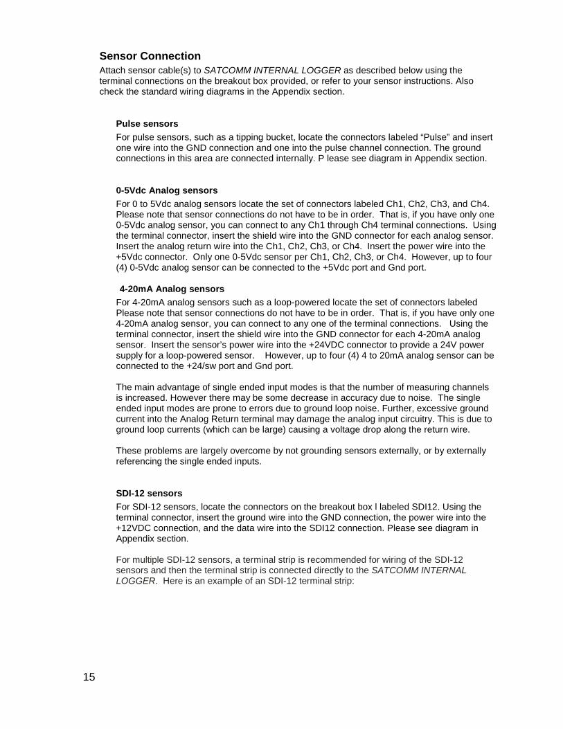
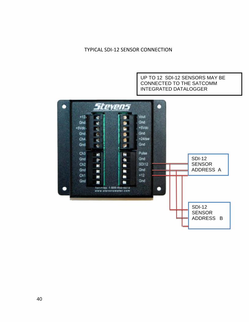
SDI-12 sensors For SDI-12 sensors, locate the connectors on the breakout box l labeled SDI12. Using the terminal connector, insert the ground wire into the GND connection, the power wire into the +12VDC connection, and the data wire into the SDI12 connection. Please see diagram in Appendix section. For multiple SDI-12 sensors, a terminal strip is recommended for wiring of the SDI-12 sensors and then the terminal strip is connected directly to the SATCOMM INTERNAL LOGGER. Here is an example of an SDI-12 terminal strip:
16
This factory installed option allows digital communication with the SATCOMM INTERNAL LOGGER that would normally be performed with the Comm1 Rs232 connection to be performed at much greater distances than the Rs232 electrical protocol allows. Rs485 communication with proper shielding and termination can span distances up to 4000 feet.
5.1.1.1 Vout The connection labeled Vout on the front panel supplies an output voltage in the range of 0 volts DC to 5 volts DC as dictated by the user's setup parameters. detail.
Grounding and Protection from Lightning Every remote environmental monitoring station should include a plan for an Earth Ground. For more information on this important topic when setting up your SATCOMM INTERNAL LOGGER, please see Appendix section

17
OPERATION
SATCOMM INTERNAL LOGGER Set Up / Configuring / Programming Logger Using SatCommSet
________________________________________________________
After you have connected your sensors and power to the SATCOMM INTERNAL LOGGER and a serial cable or a USB cable from your computer to the SATCOMM INTERNAL LOGGER, you are ready to configure the SATCOMM INTERNAL LOGGER using Stevens’ Satcomm(LoggerSet). Note: Sensor do not need to be connected to the SATCOMM INTERNAL LOGGER to configure the logger, but it is always good practice to do so to know what terminals the sensors are connected to and to enable search for SDI-12 sensors.
Install SatcommSet Install SatcommSet from the CD that accompanied your SATCOMM INTERNAL LOGGER unit, or download it from Stevens’ website at http://www.stevenswater.com/software/downloads.aspx. If the software screen does not start automatically, go to “My Computer,” click on the CD drive, and click on the setup.exe file under the SatcommSet desktop folder. . SatcommSet works on computers with Windows 2000, XP, or Vista operating systems. Insert the CD into your computer and click on setup.exe. The program will automatically check to see if your computer has .NET Framework 3.5, and if not, it will be installed automatically. This download of .NET Framework 3.5 is approximatly15MB and may take some time to install on your computer. (Note: you do not need to be concerned whether your computer has MS Visual Studio or not). If your computer already has .NET Framework 3.5, or after loading this file, the SatcommSet and Data Management program will automatically install on your computer. By default this will be placed under your computer’s program files under Stevens then under SatcommSet. SatcommSet and Data Management will also appear as desktop icon. Data Management is a Microsoft Excel macro application. You can use this application to convert the stored raw data to readable table format. (For further information on see Data Management section) You are now ready to connect to a SATCOMM INTERNAL LOGGER. First connect a power supply to the SATCOMM INTERNAL LOGGER. When you connect to any SATCOMM INTERNAL LOGGER for the first time via a USB connection, the computer will ask for the USB hardware driver. This is located on the CD under USB Driver folder. Click on the file under the USB Driver folder called “CDM 2.04.06.exe.” You only have to load the driver once and it is best to load it after a SATCOMM INTERNAL LOGGER is connected to the computer via a USB port connection. If you connect via the RS232 serial port, no driver is required.
Com Port Connections: The connection default between the SATCOMM INTERNAL LOGGER and PC is 38,400 baud and cannot be changed. This should not need any adjusting on your PC for either the RS232 or USB connection. If you connect via a USB cable, Satcomm(LoggerSet) will automatically detect the com port and show USB Serial Port (COM#). The USB Serial Port Number changes when you connect another SATCOMM INTERNAL LOGGER, so it is best to click on “refresh Com Port List” for
18
Satcomm(LoggerSet) to automatically detect the correct USB com port being used by your PC. If you connect using RS232 cable, you need to know which com port your computer is connecting to. This is usually com port 1 (Communication Port (COM 1). Once the Com Port is established, click on the “Connect” button in the upper right hand side of the main menu (see Figure 3.1). A prompt will appear stating in a pop up screen “Do you want to download the configuration for the SATCOMM INTERNAL LOGGER” Yes or No. If you click yes, Satcomm(LoggerSet) will download the SATCOMM INTERNAL LOGGER configuration setup into Satcomm(LoggerSet). You will see a time clock for a short period (less than 10 seconds) while the configuration file is being copied from the SATCOMM INTERNAL LOGGER to the Satcomm(LoggerSet). If you click NO, Satcomm(LoggerSet) will have no configuration settings.
Troubleshooting: If Satcomm(LoggerSet) say “SATCOMM INTERNAL LOGGER cannot be connected” Power to the SATCOMM INTERNAL LOGGER may not be on Cable may not be firmly connect to the SATCOMM INTERNAL LOGGER or PC Logger is busy transferring internal memory to external SD card. Contact Stevens if you still have “SATCOMM INTERNAL LOGGER cannot be connected”
problem. Disconnection Procedures. It is important to either click disconnect or close Satcomm(LoggerSet), which will automatically disconnect Satcomm(LoggerSet) from the SATCOMM INTERNAL LOGGER, and then remove the USB or serial cable from the SATCOMM INTERNAL LOGGER. If the USB or Serial cable is removed before Satcomm(LoggerSet) is disconnected, the SATCOMM INTERNAL LOGGER remains in Satcomm(LoggerSet) mode and the USB and Comm 1 ports still assume a connection. If this is done, reconnect using the same cable type (i.e. USB or Serial) that was removed prior to disconnecting Satcomm(LoggerSet). Then disconnect Satcomm(LoggerSet). Then remove the cables. NOTE: improper disconnect will not impact the logging and report of sensor data.
19
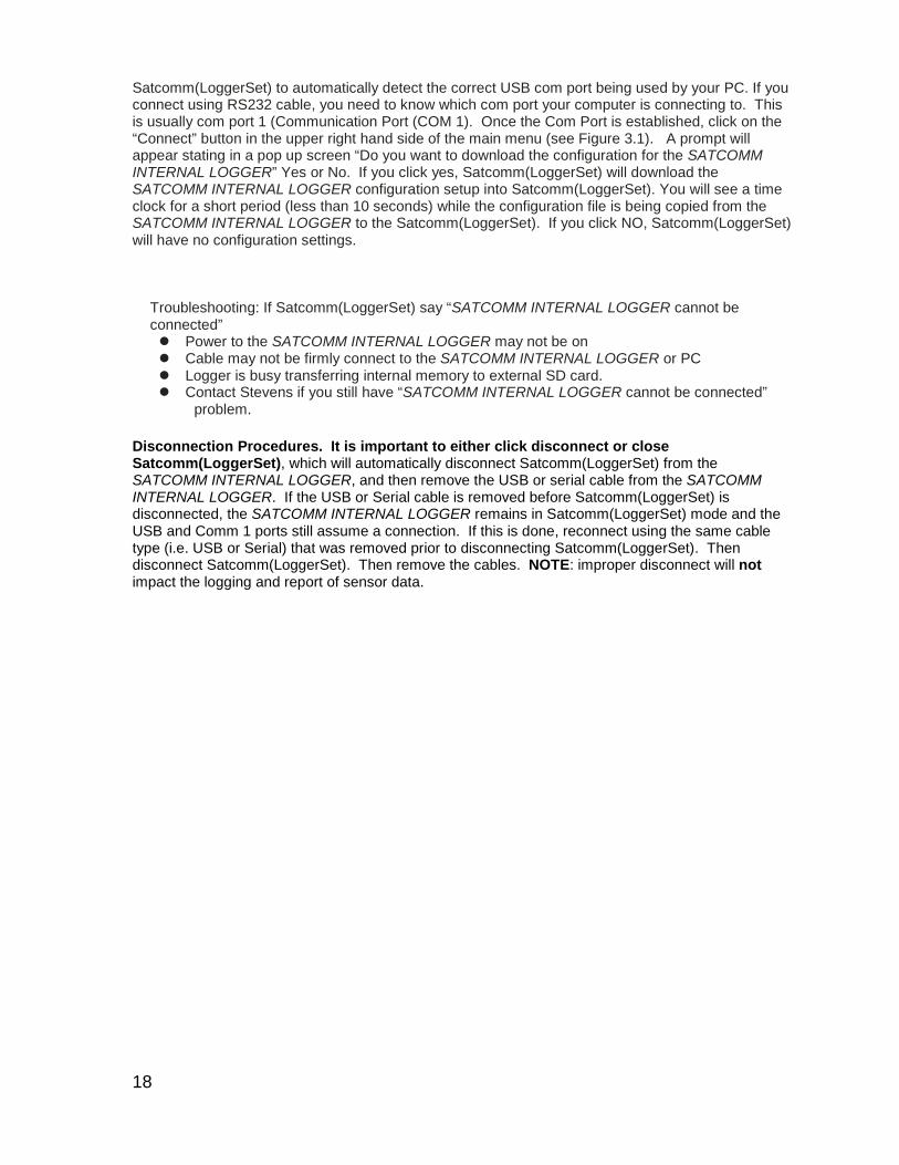
SatcommSet Main Menu
COMM PORT: click the down arrow and select appropriate comm Port. If not listed, click on “refresh Com Port List” and select appropriate Port. CONNECT: click the “Connect” button. When connection is made the button colors turn from gray to red. INTERNAL LOGGER: to activate logger click on the “Internal Logger” button. Wait until the configuration is loaded (approximately 5-7 seconds) as shown below.
20
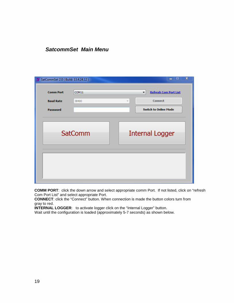
LOGGER / SUMMARY
LOGGER FIRMWARE: Firmware version that is running on the SATCOMM INTERNAL LOGGER ID: This is automatically assigned by the SATCOMM INTERNAL LOGGER firmware to be the last seven characters of the SATCOMM INTERNAL LOGGER’s globally unique MAC Address. (See MAC Address section).
21
LOGGER NAME : Assign a unique name identifier for the connected SATCOMM INTERNAL LOGGER. SYNC UP LOGGER DATE/ TIME WITH YOUR COMPUTER: Logger date /Time can be sync’d with computer by clicking the “Sync up Logger Date/Date with your computer” SUMMARY FORMAT: This provide a summary of the channel and telemetry setup for the logger. SATCOMM(LOGGERSET) – EXPANDED FORMAT: This window allow you to view the logger setup in different formats. SAVE TO FILE. Saves configuration file to your PC. NOTE: It is recommend not to click on “Upload to Logger” until you have finished filling out all configuration screens. When you have finished the entire configuration that is required for your application, click on the “Upload to Logger” button to upload your configuration to SATCOMM INTERNAL LOGGER. A copy of the current configuration will be automatically saved on your PC under C:\Program Files\Stevens\Satcomm(LoggerSet)\Configuration\xxxxxxx-upload.lcf. xxxxxxx represents the last seven(7) characters of the SATCOMM INTERNAL LOGGER’s MAC address.
Download Configuration: Download the running channel settings from SATCOMM INTERNAL LOGGER to Satcomm(LoggerSet). A copy of the SATCOMM INTERNAL LOGGER configuration will be saved on your PC automatically. This is the same as button #13 in Figure 3.1 and as described below.
Upload Configuration: Upload the current channel settings from Satcomm(LoggerSet) to SATCOMM INTERNAL LOGGER. A copy of the Satcomm(LoggerSet) configuration will be saved on your PC automatically. This is the same as button #12 in Figure 3.1 and as described below. BATTERY CHANNEL / PULSE CHANNEL

22
BATTERY CHANNEL ENABLE BATTERY CHANNEL: This enables logging / reporting of the battery voltage. BATTERY CHANNEL NAME: User defined name that the battery voltage will be logged and identified by – up to eight (8) characters. LOGGING INTERVAL: frequency of logging the battery voltage. REPORTING INTERVAL: frequency of reporting logged values if telemetry device is connected and programmed with the SATCOMM INTERNAL LOGGER. If no telemetry device, indicate “Disabled” in this field. DECIMAL PLACE: The logged value can be logged / reported up to four (4) decimal places. ALARM SETTINGS: See Alarm Settings section. PULSE CHANNEL ENABLE PULSE CHANNEL: This enables logging / reporting of the pulse sensor. PULSE CHANNEL: User defined name for logged data – up to eight (8) characters. LOGGER TIME OFFSET: Logger interval is from the top of the hour. Therefore, user may not want the interval from the top of the hours and use this time offset feature. LOGGING INTERVAL: frequency of logging the pulse sensor. REPORTING INTERVAL: frequency of reporting the logged values if telemetry device is connected and programmed with the SATCOMM INTERNAL LOGGER. If no telemetry device, indicate “Disabled” in this field. OFFSET: offset of raw readings. Default is 0 ( Raw value X Scale ) + Offset SCALE: a multiplier value of raw readings. Default is 1 ( Raw value X Scale ) + Offset DEBOUNCE DELAY(millisecond): Currently deactivated Pulse Type: Count: pulse count will be reset to 0 after each log interval. Accumulate: pulse count will be accumulated after logging until the “Reset count” button is clicked. Duration (second): Currently deactivated Decimal place: The logged value can be logged / reported up to four (4) decimal points. Alarm Setting: See Alarm Settings section.

23
Reset pulse count: If Pulse Type is set for “accumulate”, clicking on this button will reset the accumulated value to zero (0).
ANALOG CHANNELS
NUMBER OF CHANNEL: Specify the number of analog sensors connected to the SATCOMM INTERNAL LOGGER. ANALOG CHANNEL: Will automatically present the number of analog sensors connected to the SATCOMM INTERNAL LOGGER based on the number specified. BREAKOUT BOX CONNECTION: Users can select what terminal port the respective analog sensor is connecting to on the SATCOMM INTERNAL LOGGER via the sensor Breakout box. Sensors can be all 0 to 5 VDC, or all 4-20mA or a combination thereof. Refer to the breakout switch diagram. LOGGING : Logger interval is from the top of the hour. Therefore, user may not want the interval from the top of the hours and use this time offset feature. LOGGING INTERVAL: frequency of logging the analog sensor. REPORTING INTERVAL: frequency of reporting the logged values if telemetry device is connected and programmed with the SATCOMM INTERNAL LOGGER. If no telemetry device, indicate “Disabled” in this field. OFFSET: offset of raw readings. Default is 0 ( Raw value X Scale ) + Offset SCALE: a multiplier value of raw readings. Default is 1 ( Raw value X Scale ) + Offset
24
WARM UP (IN SECONDS): Specify the warm-up time, in seconds, that the SATCOMM INTERNAL LOGGER should wait after waking up, to take reading. Typically used to allow the sensor to wake up before the logger asks for current reading. DECIMAL: The logged value can be logged / reported up to four (4) decimal places. 0 V / 4mA: Set the minimum numerical measurement value returned when a sensor reads 0 V / 4mA. 5 V / 20mA: Set the maximum numerical measurement value returned when a sensor reads 5 V / 20mA. ALARM SETTING: See Alarm Settings section.
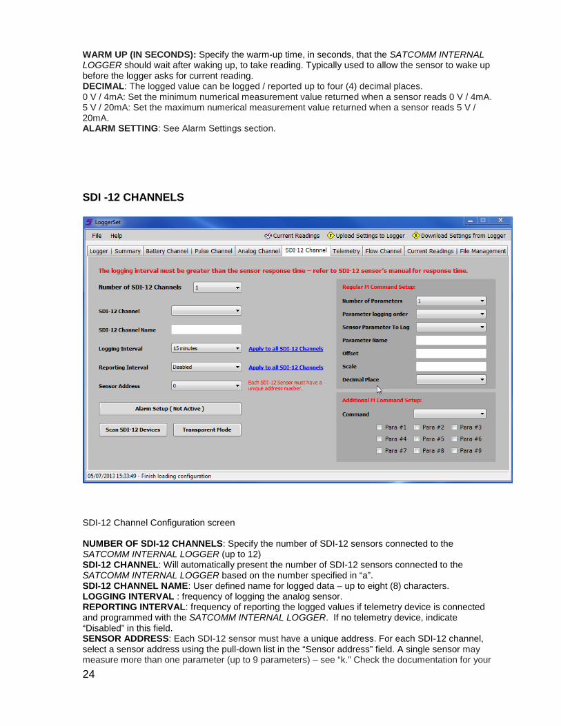
SDI -12 CHANNELS
SDI-12 Channel Configuration screen NUMBER OF SDI-12 CHANNELS: Specify the number of SDI-12 sensors connected to the SATCOMM INTERNAL LOGGER (up to 12) SDI-12 CHANNEL: Will automatically present the number of SDI-12 sensors connected to the SATCOMM INTERNAL LOGGER based on the number specified in “a”. SDI-12 CHANNEL NAME: User defined name for logged data – up to eight (8) characters. LOGGING INTERVAL : frequency of logging the analog sensor. REPORTING INTERVAL: frequency of reporting the logged values if telemetry device is connected and programmed with the SATCOMM INTERNAL LOGGER. If no telemetry device, indicate “Disabled” in this field. SENSOR ADDRESS: Each SDI-12 sensor must have a unique address. For each SDI-12 channel, select a sensor address using the pull-down list in the “Sensor address” field. A single sensor may measure more than one parameter (up to 9 parameters) – see “k.” Check the documentation for your

25
sensor to determine how to identify and change, if necessary, the SDI-12 sensor address and parameters. Alternatively, use “Scan SDI-12 Device(s)” (see “n”) to read the sensors address. NUMBER OF PARAMETERS: Specify the number of parameters to be measure by the respective SDI-12 sensor – up to 9 parameters logged per SDI-12 sensor in accordance with SDI-12 sensor protocol. PARAMETER LOGGING ORDER: Specify which parameter from the selected SDI Channel will be logged first. SENSOR PARAMETER TO LOG: Select which sensor parameter to log. PARAMETER NAME: Give the parameter a unique name to display in logged data. OFFSET: Offset of raw readings. Default is 0 ( Raw value X Scale ) + Offset SCALE : A multiplier value of raw readings. Default is 1 ( Raw value X Scale ) + Offset DECIMAL PLACE: The logged value can be logged / reported up to four (4) decimal places. ADDITIONAL M COMMAND SETTINGS: Some SDI-12 sensors support extended commands to trigger and log special parameters. These commands can be selected on this menu. Alarm Settings: See Alarm Settings Section SCAN SDI-12 DEVICE(S): Click on this to start scanning all SDI-12 sensors connected to the SATCOMM INTERNAL LOGGER. When an SDI-12 sensor is identified, the information of that sensor will be presented in the screen. Stop SCAN: The scan process will automatically stop after the SATCOMM INTERNAL LOGGER has scanned all possible SDI-12 channels. QUIT SCAN MODE: The scan process can be manually stopped by clicking on this button. SCREEN DETAILED INFORMATION: This section provides information on the SDI-12 sensor connected to the SATCOMM INTERNAL LOGGER: FOUND SENSOR ‘X’: “x” represents the sensor address SDI VERSION: the sensor’s SDI-12 version. The SATCOMM INTERNAL LOGGER can read SDI-12 versions 1.1, 1.2 or 1.3 COMPANY: the manufacture of the SDI-12 sensor MODEL NUMBER: the model number of the SDI-12 sensor SENSOR VERSION: firmware version of the SDI-12 sensor COMMENTS: extra information from the SDI-12 sensor #=NOT FOUND: cannot find any SDI-12 sensor in address # PREVIEW SCAN RESULT: preview scan result PRINT SCAN RESULT: print scan result SDI-12 Transparent Mode On the SDI-12 Channel Configuration screen click on “Transparent Mode” and the “Transparent mode” screen will appear. See Figure 3.7.3. You have the option of communicating directly with your SDI-12 sensor(s) through the “SDI-12 Transparent Mode” button. See your sensor manual for the SDI-12 commands to configure the respective sensor. To exit this mode, press the “Back to Main Menu” button. Command field: the end of the command). SEND COMMAND command that will send to the SDI-12 sensor (an exclamation mark (!) is required at: send command to the SDI-12 sensor CLEAR SCREEN: clear the screen SCREEN INFORMATION: return SDI-12 sensor’s response PREVIEW RESULT: preview transparent mode summary PRINT RESULT: print transparent mode summary

26
FLOW CHANNEL FLOW MEASUREMENT: Flow measurement is a calculated logged value using the level measurement from any one of the analog channels or SDI-12 channels. SDI-12 PARAMETER LABEL: If you select SDI-12 channel as the flow measurement channel, you have to pick one of the parameters from the selected SDI-12 channel. HEAD UNIT: Feet is the only calculation unit. FLOW UNIT: There are four different flow units. (Cubic feet per second, Gallons per second, Gallons per minute, and Million gallons per day) PRIMARY DEVICE: Six different standard shapes of the flume or weir are selectable:
• V-notch weir • Rectangular weir with end contractions • Rectangular weir without end contractions • Cipolletti (Trapezoidal) weir • Parshall flume • Palmer-Bowlus flume)
SAMPLING INTERVAL: frequency of sampling the selected channel to update the master totalizer. CREST DEGREE: Only if you select V-notch weir as the primary device. Otherwise, it will ask for the crest length. CURRENT FLOW VALUE: Current flow measurement reading. MASTER TOTALIZATION (GALLONS): Master totalization reading. RESET MASTER TOTALIZATION: Reset Master totalization reading back to 0. Password is required (Call Stevens to obtain the password)
27
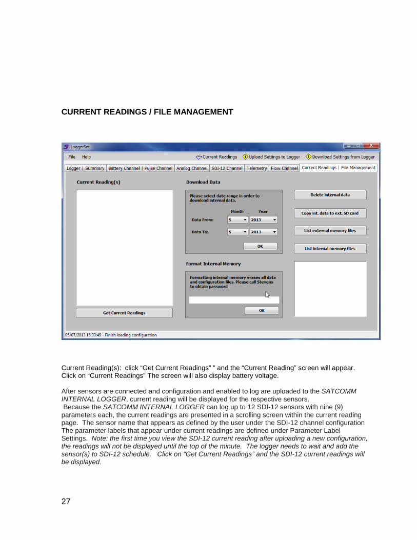
CURRENT READINGS / FILE MANAGEMENT
Current Reading(s): click “Get Current Readings” ” and the “Current Reading” screen will appear. Click on “Current Readings” The screen will also display battery voltage. After sensors are connected and configuration and enabled to log are uploaded to the SATCOMM INTERNAL LOGGER, current reading will be displayed for the respective sensors. Because the SATCOMM INTERNAL LOGGER can log up to 12 SDI-12 sensors with nine (9) parameters each, the current readings are presented in a scrolling screen within the current reading page. The sensor name that appears as defined by the user under the SDI-12 channel configuration The parameter labels that appear under current readings are defined under Parameter Label Settings. Note: the first time you view the SDI-12 current reading after uploading a new configuration, the readings will not be displayed until the top of the minute. The logger needs to wait and add the sensor(s) to SDI-12 schedule. Click on “Get Current Readings” and the SDI-12 current readings will be displayed.

28
TELEMETRY
REPORT FORMAT: Select ASCII, PSEUDO-BINARY, or PSEUDO-BINARY (EXTENDED) TRANSMIT HEADER: Select None, Channel Name, or Channel Name and Number. TRIGGER MODE: enables Trigger mode.

29
CURRENT READING / FILE MANAGEMENT
Current Reading(s)
Current Readings: will display current readings for all active parameters.
Upload Settings to Logger
This is the same process as the icon. This uploads the current channel settings from Satcomm(LoggerSet) to SATCOMM INTERNAL LOGGER. A prompt will appear stating in a pop up screen “Do you want to upload the configuration to SATCOMM INTERNAL LOGGER” Yes or No. If you click yes, Satcomm(LoggerSet) will upload the current channel settings to the SATCOMM INTERNAL LOGGER. You will see a time clock for a short period (depends on how many channels you have set up) while the configuration file is being loaded to the SATCOMM INTERNAL LOGGER. If you click no, the Satcomm(LoggerSet) will ignore the upload command.
A copy of the current configuration will be automatically saved on your PC under C:\Program Files\Stevens\Satcomm(LoggerSet)\Configuration\xxxxxxx-upload.lcf. xxxxxxx represents the last seven(7) characters of the SATCOMM INTERNAL LOGGER’s MAC address (see “a” in Figure 3.2).
30
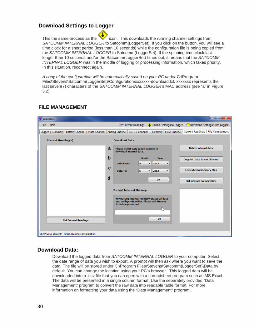
Download Settings to Logger
This the same process as the icon. This downloads the running channel settings from SATCOMM INTERNAL LOGGER to Satcomm(LoggerSet). If you click on the button, you will see a time clock for a short period (less than 10 seconds) while the configuration file is being copied from the SATCOMM INTERNAL LOGGER to Satcomm(LoggerSet). If the spinning time clock last longer than 10 seconds and/or the Satcomm(LoggerSet) times out, it means that the SATCOMM INTERNAL LOGGER was in the middle of logging or processing information, which takes priority. In this situation, reconnect again. A copy of the configuration will be automatically saved on your PC under C:\Program Files\Stevens\Satcomm(LoggerSet)\Configuration\xxxxxxx-download.lcf. xxxxxxx represents the last seven(7) characters of the SATCOMM INTERNAL LOGGER’s MAC address (see “a” in Figure 3.2).
FILE MANAGEMENT
Download Data: Download the logged data from SATCOMM INTERNAL LOGGER to your computer. Select the date range of data you wish to export. A prompt will then ask where you want to save the data. The file will be stored under C:\Program Files\Stevens\Satcomm(LoggerSet)\Data by default. You can change the location using your PC’s browser. This logged data will be downloaded into a .csv file that you can open with a spreadsheet program such as MS Excel. The data will be presented in a single column format. Use the separately provided “Data Management” program to convert the raw data into readable table format. For more information on formatting your data using the “Data Management” program.
a
b
c
d
31
DELETE INTERNAL DATA: Clears the internal data file. Historical logged data will be deleted. FORMAT INTERNAL MEMORY: Format internal memory. Everything will be deleted. If this feature is clicked on, a box will appear asking for a password to format internal memory. This should not be necessary as all memory cards are preformatted. Call Stevens to obtain the password. COPY DATA TO EXTERNAL SD CARD: Manual command to copy the data from internal memory to the external SD card. Note: the SATCOMM INTERNAL LOGGER automatically transfers logged data from internal member to SD card once per hour. LIST EXTERNAL MEMORY FILES: List the files currently stored on the external SD card currently inserted into the SATCOMM INTERNAL LOGGER’s SD card slot. LIST INTERNAL MEMORY FILES: List the files currently stored on the SATCOMM INTERNAL LOGGER’s internal memory.
ALARM SETTINGS
32
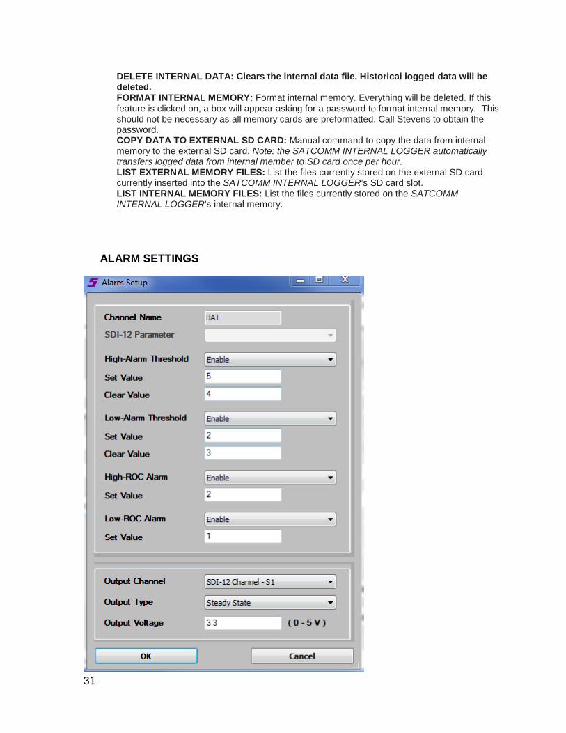
CHANNEL NAME: comes from the main Channel Configuration screen PARAMETER LABEL (FOR SDI-12 CHANNEL ONLY): pick one of the parameters from the selected SDI-12 channel HIGH-ALARM: enable or disable high alarm SET VALUE: high alarm set value. Trigger high alarm when the reading goes above the set value. CLEAR VALUE: high alarm clear value. Clear high alarm when the reading goes below the clear value. LOW ALARM: enable or disable low alarm SET VALUE: low alarm set value. Trigger low alarm when the reading goes below the set value. CLEAR VALUE: low alarm clear value. Clear low alarm when the reading goes below the clear value. HIGH-ROC ALARM: enable or disable high rate of change alarm SET VALUE: set high-roc alarm value. Trigger high-roc alarm when the reading goes above the set value. LOW-ROC ALARM: enable or disable low rate of change alarm SET VALUE: set low-roc alarm value. Trigger low-roc alarm when the reading goes below the set value. ALARM OUTPUT CHANNEL: any channel that has been setup for alarm condition ALARM OUTPUT TYPE: pulse of power for 250 ms or steady state until alarm condition is cleared ALARM OUTPUT VOLTAGE: 0 - 5v output on Vout pin
33
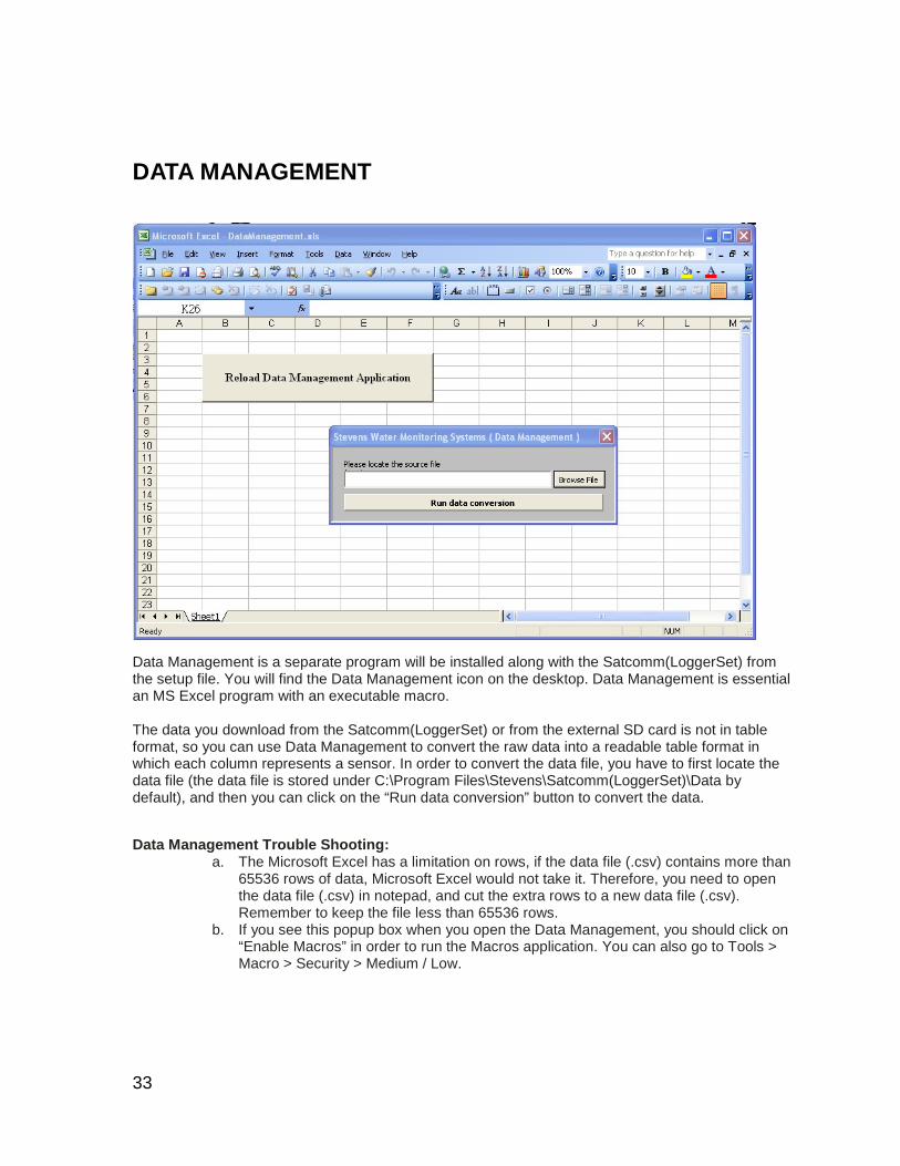
DATA MANAGEMENT
Data Management is a separate program will be installed along with the Satcomm(LoggerSet) from the setup file. You will find the Data Management icon on the desktop. Data Management is essential an MS Excel program with an executable macro. The data you download from the Satcomm(LoggerSet) or from the external SD card is not in table format, so you can use Data Management to convert the raw data into a readable table format in which each column represents a sensor. In order to convert the data file, you have to first locate the data file (the data file is stored under C:\Program Files\Stevens\Satcomm(LoggerSet)\Data by default), and then you can click on the “Run data conversion” button to convert the data.
Data Management Trouble Shooting:
a. The Microsoft Excel has a limitation on rows, if the data file (.csv) contains more than 65536 rows of data, Microsoft Excel would not take it. Therefore, you need to open the data file (.csv) in notepad, and cut the extra rows to a new data file (.csv). Remember to keep the file less than 65536 rows.
b. If you see this popup box when you open the Data Management, you should click on “Enable Macros” in order to run the Macros application. You can also go to Tools > Macro > Security > Medium / Low.

34
Raw data format (Data download from Satcomm(LoggerSet) or Data from external SD card)
Table format after conversion using Data Management
35
Maintenance and Trouble Shooting ________________________________________________________
MAINTENANCE
Battery Check battery voltage and condition during each visit to the Logger site.
a. System battery voltage: greater than 11.5 volts DC (12.0 VDC for a lead-acid battery).
Note: Logging will be discontinued if battery voltage falls below 9.6 VDC.
b. Maintain a battery log. A well-documented record and long experience are the best indicators of battery performance and condition. Battery life will be reduced with extended high temperature operation. Battery capacity will generally be reduced with extended periods of cold weather, but will recover when warmed up.
c. Rechargeable batteries will gradually lose capacity through multiple charge-discharge
cycles, with shorter operating time periods between charging cycles. Maximum operating life will be obtained when the battery and SATCOMM INTERNAL LOGGER are both connected to an appropriately filtered charger, such as the Stevens
d. Battery Charger. This provides the additional benefit of continued operation on the
battery supply, when there is intermittent power loss to the charger.
e. Observe good instrumentation grounding, shielding, and power sourcing practices to maintain maximum battery life and prolong the operating life of connected instruments.
f. Avoid using "switching" power supplies and "switching" battery chargers. Switching supplies and chargers are very noisy and can cause logging errors.
Solar Panel can also be used to obtain maximum battery life with minimum maintenance in remote field installations.
Moisture When operating in extremely humid conditions or where there may be condensation, resistance to moisture effects can be enhanced by placing a bag or two of fresh desiccant inside of the enclosure that the SATCOMM INTERNAL LOGGER will be placed in.
Cleaning If it becomes necessary to clean the SATCOMM INTERNAL LOGGER, debris or dirt should be carefully brushed off of the SATCOMM INTERNAL LOGGER with a dry, soft cloth. Avoid getting water into the logger, as it may damage the unit.
TROUBLE SHOOTING
The following is a guide to use for troubleshooting various operational problems with the SATCOMM INTERNAL LOGGER. These are conditions that should be checked before contacting the factory for assistance. If you cannot solve the problem in the field, call and ask for a Stevens Customer Technical Representative. The toll-free number for Stevens is 1-800-452-5272, and the call is free
36
from Canada or the U.S.A. For calls outside of the U.S.A. or Canada, please dial 1-503-445-8000. Customer support can also be reached via email at [email protected]. Please provide an instrument description and serial number, when possible. Many questions can be answered by telephone, or you may obtain an authorization for return of the equipment, should that be necessary. The factory is open Monday through Friday from 7 a.m. to 5 p.m., Pacific Time. If no one is available, leave a message at any time on the phone mail system; just clearly tell us your name, location, telephone number and how to reach you.
Common Troubleshooting Issues Problem: Satcomm(LoggerSet) cannot connect to SATCOMM INTERNAL LOGGER
Solutions: Power to the SATCOMM INTERNAL LOGGER may not be on. Cable may not be firmly connect to the SATCOMM INTERNAL LOGGER or PC. Logger is busy logging data – wait approximately 1 minute (depending on the number and
type of sensors connected) and reconnect. Logger is busy transferring internal memory to external SD card - SATCOMM INTERNAL LOGGER was not disconnect from Satcomm(LoggerSet) correctly. If
the USB cable or Serial cable is disconnected from the computer or SATCOMM INTERNAL LOGGER before Satcomm(LoggerSet) is disconnected by clicking on the respective Satcomm(LoggerSet) button or Satcomm(LoggerSet) is not closed, the port on the SATCOMM INTERNAL LOGGER is kept open and assumes Satcomm(LoggerSet) is still connected. • If Comm 1 cable is removed without properly disconnecting Satcomm(LoggerSet),
connection to the USB port will not work until Satcomm(LoggerSet) is reconnected via the Comm 1 port and properly disconnected.
Contact Stevens if you still have “SATCOMM INTERNAL LOGGER cannot be connected” problem
Problem: Data did not transfer to external SD card
Solutions: External SD card may be corrupted – try a different SD card. External SD card is not secured into the SD card slot properly – make sure to hear and/or
feel the SD card click into place. Problem: Current readings are not showing up Solutions: Sensor cable may not be firmly connect to SATCOMM INTERNAL LOGGER Logger is busy logging data – wait approximately 1 minute (depending on the number and
type of sensors connected) and click on current readings again.
Problem: Pulse count not showing properly on “Current Reading” screen Solutions: If the pulse channel is set to Accumulate instead of Count, the current reading page will not
give the accumulated value, but will give the number of counts since the last log event. This is not a problem.
Problem: Satcomm(LoggerSet) indicates a Logger Time under section even
37
thought SATCOMM INTERNAL LOGGER not connected : USB cable and/or Serial cable was unplugged from the SATCOMM INTERNAL LOGGER
without properly disconnected from the Satcomm(LoggerSet) (see procedure for proper disconnection). This is not a problem, but user should reconnect with the SATCOMM INTERNAL LOGGER and then properly disconnect from Satcomm(LoggerSet). Satcomm(LoggerSet) automatically retrieves the SATCOMM INTERNAL LOGGER clock time when connection is established. But than the Logger Time displayed updates on Satcomm(LoggerSet) is based on the computer’s incremental time.
Problem: Light stays on solid after disconnected USB or Serial cable. Satcomm(LoggerSet) connection was established with the SATCOMM INTERNAL
LOGGER, but no updates were executed and the USB or Serial cable were removed from the SATCOMM INTERNAL LOGGER without properly disconnecting from Satcomm(LoggerSet). Reconnect the to the SATCOMM INTERNAL LOGGER and then properly disconnect from Satcomm(LoggerSet) (see procedure for proper disconnection)
Problem: Bluetooth adapter (such as Stevens Shark) is not connecting with Satcomm(LoggerSet) even though Bluetooth connection is good. A wireless connection between the PC or PDA to the SATCOMM INTERNAL LOGGER
using Satcomm(LoggerSet) can be done with a Bluetooth radio incorporated with the PC or PDA and a RS232 Bluetooth adapter (such as Stevens Shark) attached to the SATCOMM INTERNAL LOGGER Comm1. If connection cannot be established check the following: Check to see that the RS232 Bluetooth adapter (such as the Shark) connected to the
SATCOMM INTERNAL LOGGER is configured to 38400 baud communications. Check to see if the RS232 Bluetooth adapter connected to the SATCOMM INTERNAL
LOGGER has power and is firmly connected to the SATCOMM INTERNAL LOGGER Comm 1 port.
Check the Comm port # for your PC or PDA to communicate with the RS232 Bluetooth adapter connected to the SATCOMM INTERNAL LOGGER. For PDA’s this comm. port number is often 4, 6 or 8. For a PC, this comm port number varies depending on the computer manufacture, but often in the comm. 40s range.
38
Appendix ________________________________________________________
MAC Addresses MAC addresses are also known as hardware addresses or physical addresses. A MAC address represents the physical identifier of a device on a network, while the IP address represents a logical device address on Internet Protocol networks. MAC addresses within the SATCOMM INTERNAL LOGGER are set to be either 48 bits or 64 bits in length if needed. This is done automatically through the SATCOMM INTERNAL LOGGER’s network processor. By convention, MAC addresses are usually written in one of the following two formats: MM:MM:MM:SS:SS:SS MM-MM-MM-SS-SS-SS The first half of a MAC address contains the ID number of the adapter manufacturer. These IDs are regulated by an Internet standards body’s extended unique identifier (EUI). The second half of a MAC address represents the serial number assigned to each device (in this case the SATCOMM INTERNAL LOGGER) by the manufacturer. In the example, 00:A0:C9:14:C8:29 The prefix 00A0C9 indicates the manufacturer is Intel Corporation.
Grounding and Protection from Lightning Every remote environmental monitoring station should include a plan for an Earth Ground. All sensors, loggers and telemetry devices should be bonded, or connected, to the Earth Ground in order to protect instrument circuitry from damage due to changes in electric potential. Electric potential is defined as the difference in electrical energy between two points and is typically measured in volts and is more commonly referred to simply as voltage. Assuming a ground is not needed when using a battery is often not enough because all of the paths of electric current, not just the power supply or battery, should be considered. Current will flow to ground through the path of least resistance. In a monitoring station without a good Earth Ground system, this path will most likely be through the system equipment. Primary lightning strikes occur when lightning hits the data logger or sensors directly. Such direct strikes and instruments surviving such a strike are both remote. Secondary strikes (or high transient surge currents) occur when lightning strikes somewhere near the system and induce a voltage in the wires. For example, a water level sensor in contact with the water is one path to ground. During a storm, the station’s telemetry antenna can become charged – either through nearby lightning activity or simply highly charged clouds passing overhead. This charge can cause current to flow in the system. The current will flow to ground through the antenna cable to the radio, then through the data logger and finally to the water and the water level sensor. All of these devices may be subject to damage by the high current flow.
39
The Earth serves as a constant potential reference against which all other potentials can be measured. A ground system should have appropriate current carrying capacity in order to serve as an adequate zero-voltage reference. To establish a good Earth Ground, drive a grounding rod of at least four feet in length. To the grounding rod, connect solid heavy gauge grounding wire and run that to a copper grounding plate inside the system enclosure. Avoid any sharp bends greater than 45 degrees in the wire. Inside the enclosure, connect all equipment grounds to the copper grounding plate. Do not “daisy-chain” one ground to another – each piece of equipment should have its own direct path to the plate with as short a path as possible and no sharp bends in the wires. If using bare ground wire, don’t let the wires touch or cross each other as this could cause ground loops. In laboratory / industrial applications, locating a stable earth ground is not always obvious. Consult with the respective building superintendent and/or electrician to determine if the integrity of the AC power ground and building grounding system is adequate. Every terminal on the SATCOMM INTERNAL LOGGER wiring panel, with the exception of ground terminals, have Transient / Surge Absorbers designed for high transient surge currents from sources such as lighting, inductive load switching, or capacitor bank switching. In the Transient / Surge Absorbers will heal itself from such transient surge currents, and be available for future risks of high current surges and the SATCOMM INTERNAL LOGGER will continue operating. A Transient / Surge Absorbers cannot take a direct (primary) lightning strike.
Connection Diagram
40
TYPICAL SDI-12 SENSOR CONNECTION
SDI-12 SENSOR ADDRESS A A
SDI-12 SENSOR ADDRESS B
UP TO 12 SDI-12 SENSORS MAY BE CONNECTED TO THE SATCOMM INTEGRATED DATALOGGER

41
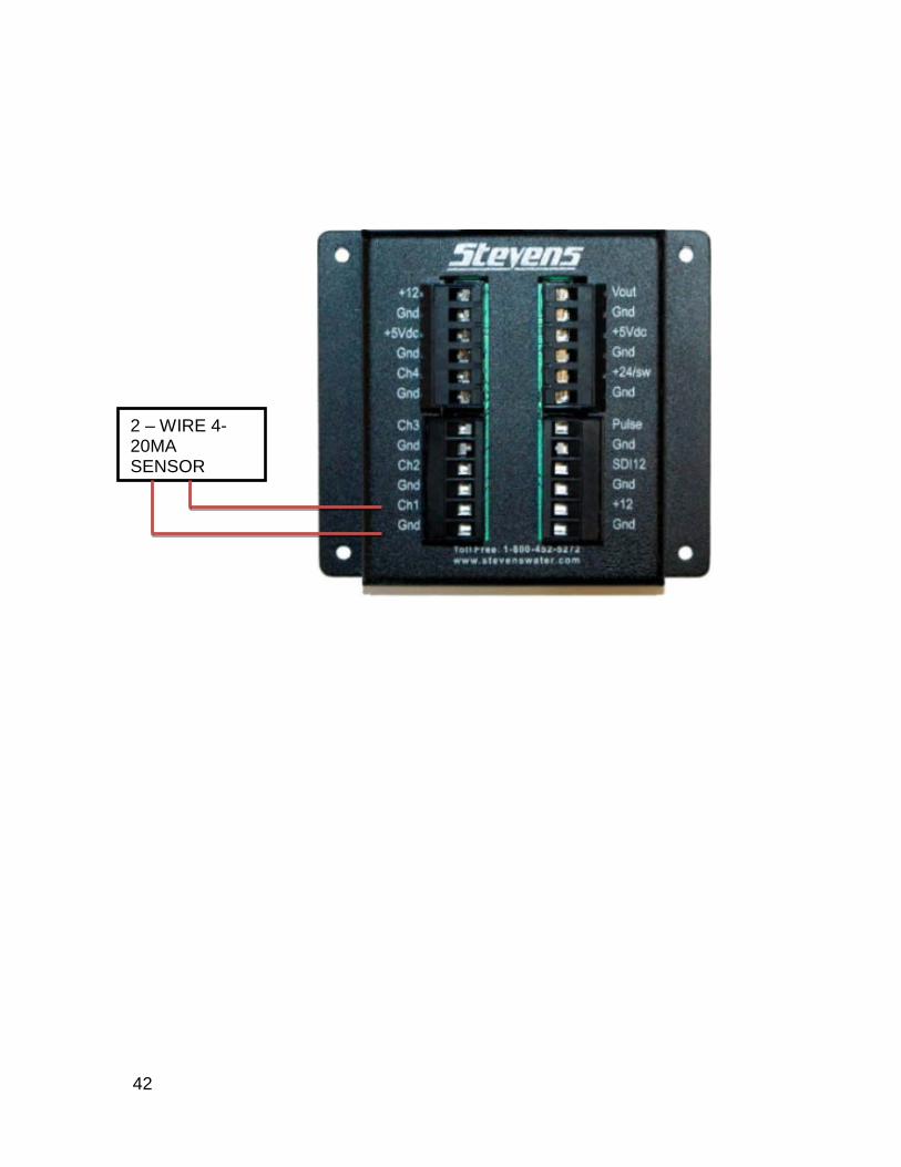
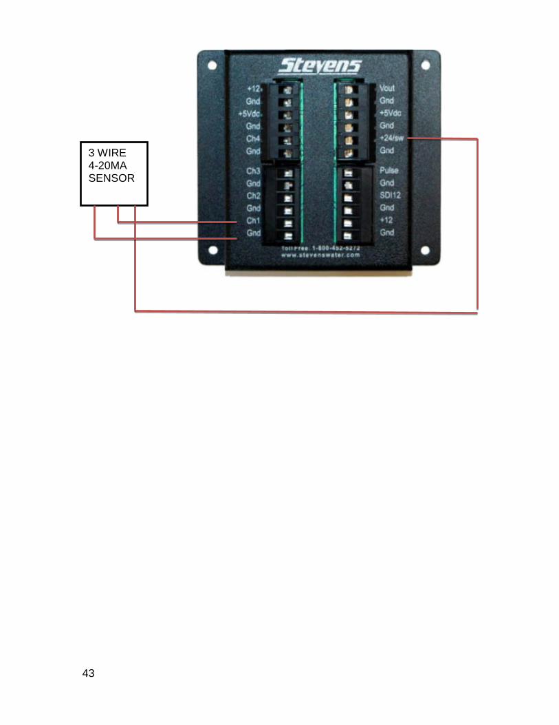
ANALOG SENSOR CONNECTIONS The switch setup for 4-20mA to 0-5 VDC is done through the internal Breakout Board. To get to the switches you will need to remove the internal board by removing the 4 Screws and making the necessary adjustment per the attached switch diagram. MAKE SURE THE SELECTOR SWITCH S1 is set to either Voltage or Current.
ANALOG 3 WIRE 3 WIRE 4-20MA SENSOR
42
2 – WIRE 4-20MA SENSOR
43
3 WIRE 4-20MA SENSOR

44
TIPPING BUCKET RAIN GAGE INPUT
TIPPING BUCKET TRANSMITTER


