77
SBC-410 Half-size 486 All-in-One CPU Card with Cache

SBC-410
Half-size 486 All-in-One CPU Cardwith Cache

FCC STATEMENTTHIS DEVICE COMPLIES WITH PART 15 FCC RULES. OPERA-TION IS SUBJECT TO THE FOLLOWING TWO CONDITIONS:(1) THIS DEVICE MAY NOT CAUSE HARMFUL INTERFER-ENCE. (2) THIS DEVICE MUST ACCEPT ANY INTERFERENCERECEIVED INCLUDING INTERFERENCE THAT MAY CAUSEUNDESIRED OPERATION.
THIS EQUIPMENT HAS BEEN TESTED AND FOUND TOCOMPLY WITH THE LIMITS FOR A CLASS "A" DIGITALDEVICE, PURSUANT TO PART 15 OF THE FCC RULES.THESE LIMITS ARE DESIGNED TO PROVIDE REASON-ABLE PROTECTION AGAINTST HARMFUL INTERFER-ENCE WHEN THE EQUIPMENT IS OPERATED IN ACOMMERCIAL ENVIRONMENT. THIS EQUIPMENT GENER-ATES, USES, AND CAN RADIATE RADIO FREQENCYENERGY AND , IF NOT INSTATLLED AND USED IN ACCOR-DANCE WITH THE INSTRUCTION MANUAL, MAY CAUSEHARMFUL INTERFERENCE TO RADIO COMMUNICA-TIONS. OPERATION OF THIS EQUIPMENT IN A RESIDEN-TIAL AREA IS LIKELY TO CAUSE HARMFUL INTERFER-ENCE IN WHICH CASE THE USER WILL BE REQUIREDTO CORRECT THE INTERFERENCE AT HIS OWN EX-PENSE.

Copyright Notice
This document is copyrighted, 1997, by AAEON Technology Inc.All rights are reserved. AAEON Technology Inc. reserves the rightto make improvements to the products described in this manual atany time without notice.
No part of this manual may be reproduced, copied, translated ortransmitted in any form or by any means without the prior writtenpermission of AAEON Technology Inc. Information provided inthis manual is intended to be accurate and reliable. However,AAEON Technology Inc. assumes no responsibility for its use, norfor any infringements upon the rights of third parties which mayresult from its use.
Acknowledgements
ALI is a trademark of Acer Laboratories, Inc.AMD is a trademark of Advanced Micro Devices, Inc.AMI is a trademark of American Megatrends, Inc.Cyrix is a trademark of Cyrix Corporation.IBM, PC/AT, PS/2 and VGA are trademarks of InternationalBusiness Machines Corporation.Intel and Pentium are trademarks of Intel Corporation.Microsoft Windows ® is a registered trademark of Microsoft Corp.SMC is a trademark of Standard Microsystems Corporation.UMC is a trademark of United Microelectronics Corporation.
All other product names or trademarks are properties of theirrespective owners.
Part No. 2007410001 2nd EditionPrinted in Taiwan May 1997
Packing listBefore you begin installing your card, please make sure that thefollowing materials have been shipped:
• 1 SBC-410 CPU card
• 1 6-pin mini-DIN dual outlet adapter for keyboard and PS/2 mouse
• 1 3½" Hard disk drive (IDE) interface cable (40 pin)
• 1 2½" Hard disk drive (IDE) interface cable (44 pin)
• 1 Floppy disk drive interface cable (34 pin)
• 1 Parallel port adapter (26 pin)
• PC/104 Expansion connector converter (pin headers)
• PC/104 Module mounting supports
If any of these items are missing or damaged, contact your distribu-tor or sales representative immediately.

Contents
Chapter 1: General Information ................................ 1
Introduction ............................................................................ 2Features................................................................................... 3Specifications .......................................................................... 4Board layout ........................................................................... 6Card dimensions ..................................................................... 7
Chapter 2: Installation................................................ 9
Jumpers and connectors ...................................................... 10Locating jumpers and connectors ........................................11Setting jumpers ..................................................................... 12Safety Precations ............................................................. 13Installing the CPU ................................................................ 13Removing a CPU .................................................................... 13Installing a CPU ...................................................................... 14CPU type select (JP1, JP2, JP3) ............................................ 15CPU Vcc select (JP7) ............................................................. 16CPU clock select (JP6, JP8) ................................................... 16Installing DRAM (SIMMs) .................................................. 17Installing SIMMs.................................................................... 17Removing SIMMs................................................................... 17Selecting cache memory size ................................................ 18Cache memory select (JP11) .................................................. 18IDE hard drive connections (Primary/ Secondary IDE) .... 19Connecting the hard drive ....................................................... 19IDE LED(CN3)....... . ........................................................20Floppy drive connections (FDC CON) ................................ 22Connecting the floppy drive .................................................... 22Parallel port (PRINTER) ..................................................... 23Installing the retaining bracket................................................. 23

Power supply connections .................................................... 24Power supply connector (POWER CON) .............................. 24CN1,2,3,8,9,11,JP4 AND JP5 locations ................................. 24Keyboard and PS/2 mouse connectors (KB-CON) ............ 25Key board or PS/3 mouse select (JP8) ................................... 25Serial ports ............................................................................ 26RS-232/422/485 select for COMB (JP12, JP13, JP14, JP15, JP16) .....................................26RS-232/422/485 serial port connections (COMA, COMB) ....26RS-422 signal wiring................................................................28RS-485 signal wiring................................................................28Watchdog timer setup......................................................... 29Watchdog timer time-out signal select (JP4) ...........................29Watchdog timer programming .................................................29SMI(System management interrupt) switch (CN11) ..............30External Switches and LEDs ............................................. 31Power LED and keylock (CN9) .............................................31External speaker (CN10) ........................................................31Reset switch (CN1) ................................................................32Turbo LED (CN2) ...................................................................32Turbo switch (CN8) ................................................................32Clear CMOS (JP9) .................................................................33Flash BIOS Protect (JP10) .....................................................33Flash BIOS Write-enable Voltage (JP17) ...............................33
Chapter 3: AMIBIOS Setup......................................... 35
General information ............................................................. 36Starting AMIBIOS setup ......................................................... 36AMIBIOS main menu............................................................. 36Using a mouse with AMIBIOS setup ...................................... 37Using the keyboard with AMIBIOS setup .............................. 37Standard Setup ..................................................................... 38Advanced Setup .................................................................... 40Chipset Setup ........................................................................ 46Power Management Setup ................................................... 48

PCI/PnP Setup ...................................................................... 49Peripheral Setup ................................................................... 53Utility ..................................................................................... 56Security .................................................................................. 57AMIBIOS password support .................................................. 57Anti-virus ................................................................................ 59Default ................................................................................... 60Original ................................................................................... 60Optimal................................................................................... 60Fail-Safe.................................................................................. 60Exiting AMIBIOS ................................................................. 61
Appendix A: Watchdog Timer Demo Program .......63
Appendix B: Installing PC/104 Modules ................... 67
Installing PC/104 modules ............................................ 68

Chapter 1 General Information 1
CH
AP
TE
R
1GeneralInformation
This chapter gives background informa-tion on the SBC-410.
Sections include:
• Card specifications
• Board layout

2 SBC-410 User's Manual
IntroductionThe SBC-410 is an all-in-one CPU card that supports L2 cachesizes from 128 KB to 512 KB (32 KB x 8, 64 KB x 8, or 128 KB x8). This CPU card uses the M1489/M1487 chipsets, which acceptIntel, AMD, Cyrix, or other compatible 486-based CPUs. The SBC-410 is fully PC/AT compatible, so your software will run withoutmodifications.
On-board features include two high-speed serial ports (RS-232 andRS-232/422/485) with 16C550 UARTs, one bi-directional parallel port,and a floppy drive controller. If program execution is halted by aprogram bug or EMI, the board's 15-stage watchdog timer canautomatically reset the CPU or generate an interrupt. This ensuresreliability in unmanned or stand-alone systems.
The SBC-410 is built with two high speed local bus Enhanced IDEcontrollers. This controller supports (through ATA PIO) mode 3 andmode 4 hard disks, which enable data transfer rates of over 11 MB/second. It connects up to four IDE devices, including large hard disks,CD-ROM drives, tape backup drives, etc. The built-in enhanced IDEcontroller provides a 4-layer 32-bit posted write-buffer and a 4-layer 32-bit read-prefetch-buffer to boost IDE performance.
The SBC-410 supports 5V EDO DRAM. It also provides two 72-pinSIMM (Single In-line Memory Module) sockets for on-board DRAM.This gives you the flexibility to configure your system memory from 1~ 64 MB using the most economical combination of SIMMs.
The SBC-410 also features power management to minimize powerconsumption. It uses CMOS components and complies with the"Green Function" standard.
If you need any additional functions, you can add industry-standardPC/104 expansion modules. We provide numerous PC/104 modules tomeet your system requirements.

Chapter 1 General Information 3
Features• Accepts any Intel, AMD, Cyrix, or other compatible processor
• Half-size ISA bus CPU card, fully 486SX/DX/DX2/DX4/5x86/PentiumOver Drive compatible
• Built-in 128 KB secondary cache, up to 512 KB
• Up to 64 MB of on-board DRAM; supports 5V EDO DRAM
• Built-in IDE (AT bus) hard disk drive interface, floppy drive controller
• One RS-232 and one RS-232/422/485 selectable serial port; uses16C550 UARTs with 16-byte FIFO
• One bi-directional parallel port
• 32 to 140oF (0 to 60oC) operating temperature
• Watchdog timer, software programmable from 2 to 32 seconds(15 steps, 2 seconds per step)
• On-board keyboard connector and/or PS/2 mouse
• IDE HDD auto-detection
• Connectors for PC/104 module expansion
• Single +5V power supply
• "Green" function, supports power management

4 SBC-410 User's Manual
Specifications• CPU: Intel 486SX/DX/DX2/DX4/Pentium Over Drive;
AMD Am486DX/DX2/DX4/5x86;IBM/SGS/Cyrix Cx486DX/DX2/M7/5x86;TI 486DX2/DX4
• Bus interface: ISA (PC/AT) bus
• Data bus: 32 bit
• Processing ability: 32 bit
• Chipset: ALI 1489/1487
• RAM memory: 1 MB to 64 MB, two 72-pin sockets
• Shadow RAM memory: Supports system and video BIOS upto 256 KB in 32 KB blocks
• L2 Cache memory: On-board 128 KB, up to 512 KB (DIP package)
• Enhanced IDE HDD interface: Supports up to four enhanced IDE(ATA-2 bus) large hard disk drives or other enhanced IDE devices.Supports mode 3 and mode 4 hard disks (minimum data transferrate of 11.1 MB/sec).
• Floppy disk drive interface: Supports up to two floppy disk drives,5.25" (360 KB and 1.2 MB) and/or 3.5" (720 KB, 1.44 and 2.88 MB).
• Bi-directional parallel port : SPP/EPP/ECP standards.
• Serial ports: One serial RS-232 port and one serial RS-232/RS-422/RS-485 port, jumper selectable. Both with 16C550 UARTs with16-byte FIFO buffer.
• IRQ SELECTION FOR COM PORTS:COMA: Supports COM 1/2/3/4 & address is selectable;COMB: Supports COM 1/2/3/4 & address is selectable;
• BIOS: AMI Flash WinBIOS
• Watchdog timer: The time interval is software selectable from 2 to 32seconds (15 steps, 2 seconds per step). Can generate a system reset orIRQ15.
• PC/104: 104-pin connector for a 16-bit bus

Chapter 1 General Information 5
• DMA channels: 7
• Interrupt levels : 15
• Keyboard connector: A 6-pin mini DIN keyboard connector is locatedon the mounting bracket for easy access. An on-board keyboard 5-pinheader connector is also available.
• PS/2 Mouse connector: Shared with keyboard connector.
• Bus speed: 8 MHz
• System performance: 325 MHz in 80486DX4-100 (Landmark V2.0)
• Max. power requirements: +5 V @ 2.5 A
• Power supply voltage: Single +5 V (4.75 V to 5.25 V)
• Operating temperature: 32 to 140oF (0 to 60oC); must use a cooling fanwhen using a DX4-100 CPU or above
• Board size: 7.3" (L) x 4.8" (W) (185 mm x 122 mm)
• Board weight: 1.2 lbs (0.5 Kg)
• Green Function: Yes

6 SBC-410 User's Manual
Board layout
SM
CF
DC
37C
665
OD
INO
EC
12C
887
ALI
M1489
14.318
24MHz
SC
464
IMI
MA
X2
11
MA
X2
11
ME
GA
-KB
ALI
M1487
SBC-410 486DX4/5X86 CPU CARD REV:.A1
32K
8 C
AC
HE
RA
M
32K
8 C
AC
HE
RA
M
32K
8 C
AC
HE
RA
M
32K
8 C
AC
HE
RA
M
16V
8
AM
ER
ICA
N M
EG
AT
RE
ND
SA
MIB
IOS
486P
CI
ISA
9644
SU
M61
256F
S-1
5

Chapter 1 General Information 7
Card dimensions
Units=mm
PC
/104
Mod
ule
185.
0017
8.00
98.50
122.00
80.65
73.6
626
.00
19.00
19.50
D4x
4

8 SBC-410 User's Manual

Chapter 2 Installation 9
2Installation
This chapter describes how to set up theSBC-410 hardware, including instruc-tions on setting jumpers and connectingperipherals, switches and indicators. Besure to read all safety precautions beforeyou begin the installation procedure.
CH
AP
TE
R

10 SBC-410 User's Manual
Jumpers and connectorsConnectors on the board link it to external devices such as harddisk drives, a keyboard or floppy drives. In addition, the board hasa number of jumpers that allow you to configure your system tosuit your applications.
The table below lists the function of each of the board jumpersand connectors.
Jumpers and connectors
Label FunctionCN1 Reset switchCN2 Turbo LEDCN3 IDE LEDCN8 Turbo switchCN9 Power LED and keylock voltageCN10 External speakerCN11 SMI SWITCHJP1, 2, 3 CPU type selectJP4 Watchdog timer time-out signal selectJP6,8 CPU clock selectJP7 CPU Vcc selectJP9 Clear CMOSJP10 Flash BIOS ProtectJP11 Cache memory selectJP12, 13, 14, 15, 16 RS-232/422/485 selectJP17 Flash BIOS Write-enableJP18 Keyboard or PS/2 mouse selectPRIMARY IDE Primary Enhanced IDE connectorSECONDARY IDE Secondary Enhanced IDE connectorFDC CON FDD connectorPRINTER Parallel connectorPOWER CON Power connectorKB-CON External keyboard connectorKB-CON Keyboard and/or PS/2 mouse connectorCOMA Serial port 1COMB Serial port 2

Chapter 2 Installation 11
SM
CF
DC
37
C6
65
OD
INO
EC
12
C8
87
ALI
M1
48
914.318
24MHz
SC
46
4IM
I
MA
X2
11
MA
X2
11
ME
GA
-KB
ALI
M1
48
7
SBC-410 486DX4/5X86 CPU CARD REV:.A1
32
K8
CA
CH
E R
AM
32
K8
CA
CH
E R
AM
32
K8
CA
CH
E R
AM
32
K8
CA
CH
E R
AM
16
V8
AM
ER
ICA
N M
EG
AT
RE
ND
SA
MIB
IOS
48
6P
CI
ISA
96
44
SU
M6
12
56
FS
-15
Locating jumpers and connectors
POWER CON JP10 COMA COMB KB-COM
PRINTER
JP17
JP9
CN1,2,3,8,9,10,11and JP4,5
FDC CON
JP 6,8JP1,2,3
JP7
PRIMARY IDE
SECONDARY IDE
KB-COMJP12,13,14,15,16JP18
JP11
SIMM

12 SBC-410 User's Manual
Setting jumpersYou configure your card to match the needs of your application bysetting jumpers. A jumper is the simplest kind of electric switch.It consists of two metal pins and a small metal clip (oftenprotected by a plastic cover) that slides over the pins to connectthem. To "close" a jumper you connect the pins with the clip. To"open" a jumper you remove the clip. Sometimes a jumper willhave three pins, labeled 1, 2 and 3. In this case you would connecteither pins 1 and 2 or 2 and 3.
The jumper settings are schematically depicted in this manual asfollows:
A pair of needle-nose pliers may be helpful when working withjumpers.
If you have any doubts about the best hardware configuration foryour application, contact your local distributor or sales represen-tative before you make any changes.
Generally, you simply need a standard cable to make mostconnections.
132
Open Closed Closed 2-3
Open Closed Closed 2-3
1 2 3

Chapter 2 Installation 13
Safety Precantions
Warning! Always completely disconnect the power cordfrom your chassis whenever you are working onit. Do not make connections while the power ison, sensitive electronic components can bedamaged by the sudden rush of power. Onlyexperienced electronics personnel should openthe PC chassis.
Caution! Always ground yourself to remove any staticcharge before touching the CPU card. Modernelectronic devices are very sensitive to staticelectric charges. Use a grounding wrist strap atall times. Place all electronic components on astatic-dissipative surface or in a static-shieldedbag when they are not in the chassis.
Installing the CPUThe SBC-410 CPU card supports most 486 CPUs. The system'sperformance depends on the CPU you choose. You can install orupgrade the CPU in the board's PGA socket by following theprocedures outlined below. If your system has an existing CPU,you need to remove it before installing the new CPU.
Removing a CPU
1. Disconnect power from the chassis, and unplug all connec-tions to the CPU card. Then, remove the CPU card from thechassis by following the instructions in the user's manual foryour chassis.
2. Lift the CPU out of the PGA socket. The old chip may bedifficult to remove. You may find spray chip lubricant,designed for pin-grid-array (PGA) devices, and a chip pullerhelpful. These are available at electronics hobbyists' supplystores.

14 SBC-410 User's Manual
Installing a CPU
To install the CPU, follow the instructions that came with it. If nodocumentation is provided, the general procedure for installing aCPU are outlined below:
1. Lubricate the pins on the CPU with lubricant for PGA devices.This makes the CPU slide in much easier and greatly reducesthe chance of damaging the pins and other components.
2. Carefully align the CPU so that it is parallel to the socket.Make sure that the notch on the corner of the CPU matchesthe notch on the inside of the socket.
3. Gently push the CPU into the socket. There will probably be asmall gap between the CPU and the socket even when it isfully seated. DO NOT USE EXCESSIVE FORCE!
When you install a new CPU, you may have to adjust othersettings on the board, such as CPU type, CPU clock and PCIspeed, to accommodate it. Make sure that the settings are correctfor your CPU. Improper settings may damage the CPU.

Chapter 2 Installation 15
Pin 1
2
3
4
5
6
7
8
9
Pin 1
2
3
4
5
6
7
8
9
Pin 1
2
3
4
5
6
7
8
9
JP 1 2 3 JP 1 2 3 JP 1 2 3JP 1 2 3
Pin 1
2
3
4
5
6
7
8
9
Pin 1
2
3
4
5
6
7
8
9
Pin 1
2
3
4
5
6
7
8
9
JP 1 2 3 JP 1 2 3
Pin 1
2
3
4
5
6
7
8
9
JP 1 2 3
CPU type select (JP1, JP2, JP3)
JP1, JP2, and JP3 must be set to match the CPU type. The chartbelow shows the proper jumper setting for their respective CPU.
CPU Type select (JP1, JP2, JP3)Intel P24T AMD/Intel DX4 Series *AMDX5-133/ Intel 486SX Intel P24D AMD DX2-66(WB) Intel DX2-66 (default) AMD DE2-66
Cyrix/IBM/ST Cyrix/IBM/ST/TI AMD5x86 , DX4 DX2 Series DX2-66(WT)Series

16 SBC-410 User's Manual
CPU Vcc select (JP7)
JP7 must be set to match its CPU type. The chart below shows theproper jumper settings for itsVcc.
CPU Vcc select (JP7)
5.0 V 3.3 V 3.45 V* 3.6 V 4.0 V
JP7
CPU clock select (JP6, JP8)
JP6 and JP8 are used to synchronize the CPU clock with the CPUtype. Set the CPU clock according to the base CPU speed.
CPU clock select (JP6, JP8)
25 MHz 33 MHz* 40 MHz 50MHz
2
2
2
2
2
2
1
1
1
1
1
12
12
1 1
211
11 333
*default
*default
3

Chapter 2 Installation 17
Installing DRAM (SIMMs)The SBC-410 CPU card provides two 72-pin SIMM (Single In-line Memory Module) sockets and supports between 1 MB to 64MB of RAM.
When installing SIMMs, make sure that Bank 1 is filled first.
Installing SIMMs
Note that the modules can only fit into a socket one way.
1. Insert the memory module into the socket at a moderate angle.
2. Push the module toward the vertical posts at both ends of thesocket until the module is upright, and the retaining clips atboth ends of the module click into place. When positionedcorrectly, the pins on top of the vertical posts should corre-spond to the circular holes on the ends of the module.
3. Repeat steps 1 and 2 for each module you install.
Removing SIMMs
If you need to remove a SIMM, follow the procedures below:
1. Supporting the SIMM with a finger, use a pen or a similarlyshaped object and press one retaining clip straight down.
2. Repeat for the other side. When released, the retaining clipswill push the SIMM up and out of its upright position.
3. Carefully pull the SIMM out of the socket with your fingers.
4. Repeat the above steps for each module you remove.

18 SBC-410 User's Manual
Selecting cache memory sizeThe SBC-410 features a 2nd level memory cache that supports128, 256, or 512 KB of cache memory. Higher cache memorycan improve your system's performance.
The cache uses SRAM chips in three sizes: 32 KB, 64 KB and128 KB. The on-board cache memory banks consists of fourSRAM chip sockets, each of which accepts one "Tag" chip. AllSRAM chips must have a speed of 20 ns or faster. The table belowshows the possible cache configurations:
Cache Configuration
Cache size Tag RAM Data RAM128 KB one 32 K x 8 four 32 KB x 8 SRAMs256 KB one 32 K x 8 four 64 KB x 8 SRAMs512 KB one 32 K x 8 four 128 K x 8 SRAMs
Cache memory select (JP11)
When the cache size changes, you must make sure that JP11 is setto match the new cache memory size. The following chart showsthe proper jumper setting for each cache configuration:
Cache memory select (JP11)
128 KB* 256 KB 512 KB
*default
2 4
1 3
2 4
1 3
2 4
1 3

Chapter 2 Installation 19
IDE hard drive connections (Primary/Secondary IDE)
You can attach up to four Enhanced Integrated Device Electronicshard disk drives to the SBC-410's internal controllers. The cardcomes with a 40-pin and a 44-pin flat-cable piggyback cables. The40-pin flat-cable has three identical 40-pin connectors.
Connecting the hard drive
Wire number 1 on the cable is red or blue, and the other wires aregray.
1. Connect one end of the cable to Primary IDE or SecondaryIDE on the CPU card. Make sure that the red (or blue) wirecorresponds to pin 1 on the connector, which is labeled on theboard (on the right side).
2. Plug the other end of the cable to the Enhanced IDE harddrive, with pin 1 on the cable corresponding to pin 1 on thehard drive. (See your hard drive's documentation for thelocation of the connector.)
Unlike floppy drives, you can make the connections with any ofthe connectors on the cable. If you install two drives, you willneed to set one as the master and one as the slave. You do thisusing jumpers on the drives. If you install just one drive, set it asthe master.

20 SBC-410 User's Manual
IDE LED (CN3)You can connect a LED to indicate that an IDE device is in use.The pin assignments for this jumper are as follows:
IDE LED pin assignments (CN3)
Pin Function1 -R/W IDE2 Pull high
Pin assignmentsThe following table lists the pin numbers and their respectivesignals:
40 Pin IDE hard drive connector (PRIMARY IDE)
Enhanced IDE connector (PRIMARY IDE)
Pin Signal Pin Signal1 Reset 2 GND3 D7 4 D85 D6 6 D97 D5 8 D109 D4 10 D1111 D3 12 D1213 D2 14 D1315 D1 16 D1417 D0 18 D1519 GND 20 N.C.21 N.C. 22 GND23 IOW 24 GND25 IOR 26 GND27 IORDY 28 BALE29 N.C. 30 GND31 IRQ 32 -I/O CS1633 A1 34 N.C.35 A0 36 A237 CS0 38 CS139 -ACT 40 GND

Chapter 2 Installation 21
44 Pin IDE hard drive connector (SECONDARY IDE)
Enhanced IDE connector (SECONDARY IDE)
Pin Signal Pin Signal1 IDE RESET 2 GND3 DATA7 4 DATA85 DATA6 6 DATA97 DATA5 8 DATA109 DATA4 10 DATA1111 DATA3 12 DATA1213 DATA2 14 DATA1315 DATA1 16 DATA1417 DATA 0 18 DATA1519 SIGNAL GND 20 N.C.21 N.C. 22 GND23 IO WRITE 24 GND25 IO READ 26 GND27 IO CHANNEL READY 28 N.C.29 N.C. 30 GND31 IRQ 14 32 IOCS1633 ADDR 1 34 N.C.35 ADDR 0 36 ADDR 237 HARD DISK SELECT 0 38 HARD DISKSELECT 139 IDE ACTIVE 40 GND41 VCC 42 MVCC43 GND 44 N/C

22 SBC-410 User's Manual
Floppy drive connections (FDC CON)You can attach up to two floppy disks to the SBC-410's on-boardcontroller. You can use any combination of 5.25" (360 KB and 1.2MB) and/or 3.5" (720 KB, 1.44 MB, and 2.88 MB) drives.
The SBC-410 CPU card comes with a 34-pin daisy-chain driveconnector cable. On one end of the cable is a 34-pin flat-cableconnector. There are two sets of floppy disk drive connectors,one in the middle, and one on the other end. Each set consists of a34-pin flat-cable connector (usually used for 3.5" drives) and aprinted-circuit board connector (usually used for 5.25" drives).
Connecting the floppy drive
1. Plug the 34-pin flat-cable connector into FDC CON on theCPU card.
2. Attach the appropriate connector on the other end of the cableto the floppy drive(s). You can use only one connector in theset. The set on the end (after the twist in the cable) connectsto the A: floppy. The set in the middle connects to the B:floppy.
Pin assignmentsThe following table lists the pin assignments for FDC CON:
Floppy disk connector (FDC CON)
Pin Signal Pin Signal1~33(odd) GND 2 High density4, 6 Unused 8 Index10 Motor enable A 12 Driver select B14 Driver select A 16 Motor enable B18 Direction 20 Step pulse22 Write data 24 Write enable26 Track 0 28 Write protect30 Read data 32 Select head34 Disk change

Chapter 2 Installation 23
Parallel port (PRINTER)Normally, the parallel port is used to connect the card to aprinter. The SBC-410 includes an on-board parallel port, whichis accessed through a 26-pin flat-cable connector. The CPUcard comes with an adapter cable, which lets you use a tradition-al DB-25 connector. The cable has a 26-pin connector on oneend and a DB-25 connector on the other, mounted on a retainingbracket.
Installing the retaining bracket
The retaining bracket installs at an empty slot in your system'schassis. It provides an external port that allows your parallelperipheral to access to the card's parallel port connector.
1. Find an empty slot in your chassis.
2. Unscrew the plate that covers the end of the slot.
3. Screw in the bracket in place of the plate.
4. Next, attach the flat-cable connector to PRINTER on theCPU card. Wire 1 of the cable is red or blue, and the otherwires are gray. Make sure that Wire 1 connects to Pin 1 ofthe PRINTER connector. Pin 1 is on the right side ofPRINTER.
Pin assignments
Parallel port connector (PRINTER)
Pin Signal Pin Signal1 Strobe 2 Data 03 Data 1 4 Data 25 Data 3 6 Data 47 Data 5 8 Data 69 Data 9 10 -Acknowledge11 Busy 12 Paper empty13 + Select 14 - Auto feed15 - Error 16 - Init printer17 - Select input 18~25 GND

24 SBC-410 User's Manual
Power supply connections
Power supply connector (POWER CON)
In single-board-computer (non-passive-backplane) applicationsyou will need to connect power directly to the SBC-410 boardusing POWER CON. This connector is fully compatible with thestandard PC power supply connector. See the following table forits pin assignments:
Power connector (POWER CON)
Pin Function1 N.C.2 +5 VDC
3 +12 VDC
4 -12 VDC
5 GND6 GND
CN1,2,3,8,9,10,11,JP4 AND JP5 locations
CN9 CN10
CN1 JP5(reserved)
(Pin 4 is
reserved )
CN11 CN2 JP4
CN8 CN3

Chapter 2 Installation 25
Keyboard and PS/2 mouseconnectors (KB-CON)
The SBC-410 board provides two keyboard connectors. A 5-pinconnector supports passive backplane applications. A second 6-pin mini-DIN connector on the card mounting bracket supportssingle-board-computer applications. The card comes with anadapter to convert the 6-pin mini-DIN connector, used for themouse, and the standard AT keyboard connector.
5-pin Keyboard or PS/2 mouse connector (KB-CON)
Pin Function1 K.B. clock or PS/2 clock (select by JP18)2 K.B. data or PS/2 data (select by JP18)3 N.C.4 GND5 +5 VDC
6-pin mini-DIN Keyboard or PS/2 mouse connector (KB-CON)
Pin Function1 K.B. data2 PS/2 mouse data3 GND4 +5 VDC
5 K.B. clock6 PS/2 mouse clock
Keyboard or PS/2 mouse select (JP18)You can select keyboard input or PS/2mouse input for 5-pin KB-CON connector.
Keyboard or PS2 mouose select (JP18)
KB* PS/2 mouse
*default
2
1
6 2
1
6
55

26 SBC-410 User's Manual
JP1
3
JP1
4
JP1
5
JP1
6
JP12
JP1
3
JP1
4
JP1
5
JP1
6
JP12
JP1
3
JP1
4
JP1
5
JP1
6
JP12
Serial portsThe SBC-410 offers two serial ports: one RS-232 and one RS-232/422/485. Using the BIOS Peripheral Setup program, you canselect the address for each port or disable it.
The card mounting bracket has two serial port connectors. TheDB-9 connector on the top of the bracket is COMA, the RS-232serial port. The DB-9 connector on the bottom of the bracket isCOMB, the RS-232/422/485 serial port.
RS-232/422/485 select for COMB(JP12, JP13, JP14, JP15, JP16)
RS-232 serial ports are widely used for external input/outputdevices. The RS-422 and RS-485, however, are popular forindustrial and laboratory applications because they offer highnoise resistance and long range communication (up to 4000 ft,1200 m). The RS-422 is commnly used for two-way communica-tion between two devices, where as RS-485 is used for communi-cation between a single master and a network of slave modules.
COMA is the RS-232 serial port, and COMB can function as anRS-232, RS-422, or RS-485, depending on the jumper settingsfrom JP12, JP13, JP14, JP15 and JP16. To select the desiredserial port type for COMB, adjust JP12, JP13, JP14, JP15, andJP16:
RS-232/422/485 select for COMB (JP12, JP13, JP14, JP15, JP16)
RS-232*
RS-422
RS-485
*default
1
5
1
1
1
1
1
5
5
3
3
3

Chapter 2 Installation 27
RS-232/422/485 serial port connections(COMA, COMB)
Pin assignmentsThe following table shows the pin assignments for the card'sRS-232 and RS-422/485 (COMB) serial port connectors:
RS-232 (COMA, COMB) RS-422/485 (COMB)
Pin Signal Pin Signal1 DCD 1 TX- (DTE)2 RX 2 TX+ (DTE)3 TX 3 RX+ (DTE)4 DTR 4 RX- (DTE)5 GND 5 Ground6 DSR 6 RTS-7 RTS 7 RTS+8 CTS 8 CTS-9 RI 9 CTS-

28 SBC-410 User's Manual
RS-422 signal wiringRS-422 is used for long-distance point-to-point connections. RS-422 originally used four wires for one-way communication (withdevices such as display terminals or printer) but was later adoptedby the industry for simultaneous two-way communication bydoubling the number of wires.
Each pin on the first device connects to a corresponding deviceon the second. Flow control lines manage the communication.The following table shows pin connections.
Computer A Computer B
Pin Signal Pin Signal1 TX- > 4 RX-2 TX+ > 3 RX+3 RX+ < 2 TX+4 RX- < 1 TX-5 Ground < 5 Ground6 RTS- > 9 CTS-7 RTS+ > 8 CTS+8 CTS+ < 7 RTS+9 CTS- < 6 RTS-
RS-485 signal wiringIn a typical RS-485 application, the host device requests datafrom a slave module then listens for the response. The hosttransmits and receives data on the same pair of wires. Softwarehandles the flow control; no other wires are needed.
Pin assignments appear in the following table. Pins 1 and 4 sharethe Data- wire. Pins 2 and 3 share the Data+ wire.
Computer A Device B
Pin Signal Pin Signal
1 TX- Data-
1 TX-4 RX- 4 RX-2 TX+ 2 TX+3 RX+ Data+ 3 RX+5 Ground 5 Ground

Chapter 2 Installation 29
1 2 3 1 2 3
Watchdog timer setup
Watchdog timer time-outsignal select (JP4)
If CPU processing comes to a halt because of EMI or softwarebug, the watchdog timer can either reset the CPU or signal aninterrupt on IRQ15.
Watchdog timer time-out signal select (JP4)
Reset CPU* IRQ15
* default
Watchdog timer programming
The watchdog timer must be programmed to write to I/O portaddress 443 at an interval shorter than the timer's preset interval.The timer's interval has a tolerance of ±5%, so you shouldprogram an instruction that will refresh the timer before a time-out occurs. The following steps illustrate how you mightprogram the watchdog timer.

30 SBC-410 User's Manual
1. Write to I/O port 443 (Hex) and designate a time-out interval.This will enable the watchdog and set up its time-out interval.
2. Write to I/O port 080 (Hex) and any random value. This will inturn disable the watchdog timer.
The watchdog timer-out interval can be set at 15 levels between 2and 32 seconds. The following table shows the Hex values for theappropriate time-out intervals:
Watchdog timer delay values
Delay time Value (Hex) Delay time Value (Hex)0~2 F 16~18 72~4 E 18~20 64~6 D 20~22 56~8 C 22~24 48~10 B 24~26 310~12 A 26~28 212~14 9 28~30 1
SMI (System Management interrupt) switch (CN11)You can connect an extrnal switch to allow your computer toenter suspend mode.
SMI switch (CN11)
Pin Function Suspend mode Normal mode*1 SMI2 Ground*default

Chapter 2 Installation 31
External Switches and LEDs
Power LED and keylock (CN9)
You can connect an LED to indicate when the CPU card is on. Pin1 of CN9 supplies power to the LED and Pin 3 is the ground.
You can use a switch (or a lock) to disable the keyboard. In thisstate the PC will not respond to any input. This is useful if youdon’t want anyone to change or stop a running program. Simplyconnect the switch between Pins 4 and 5. The pin assignmentsappear in the following table:
Power LED and keylock (CN9)
Pin Function1 LED Power (+5 V)2 No Connector3 Ground4 Keyboard lock5 Ground
External speaker (CN10)
The CPU card has its own buzzer. You can disable the internalbuzzer and connect an external speaker to CN10. Enabling theexternal speaker automatically disables the internal buzzer.
External speaker (CN10)
Pin Function1 Vcc2 Speaker output3 Buzzer in4 Speaker output

32 SBC-410 User's Manual
Reset switch (CN1)
You can connect an external switch to easily reset your comput-er. This switch restarts your computer as if you had turned offthe power then turned it back on. The following table shows thepin assignments for the CN1.
Reset switch (CN1)
Pin Function1 Ground2 Reset
Turbo LED (CN2)
You can connect a LED indicator across CN2 to indicate whenthe CPU is in Turbo mode. Marks on the circuit board indicateLED polarity (the pin on the left is positive).
Turbo LED (CN2)
Pin Function1 Turbo2 Ground
Turbo switch (CN8)
You can connect a switch across the pins of CN8 to change theCPU speed between Turbo and non-Turbo mode. When youleave the pins open, the CPU card operates at full speed. Whenyou close the pins, the card operates at slow speed for compati-bility with older software.
Turbo switch (CN8)
Pin Function Low speed High Speed1 - Deturbo2 Pull low
*default
*

Chapter 2 Installation 33
*
*default
*default
*default
Clear CMOS (JP9)
You can connect an external switch to clear CMOS. This switchcloses JP9 and turns off the power, at which time the CMOSsetup can be cleared.
Clear CMOS (JP9)
Protect Clear CMOS
Flash BIOS Protect (JP10)
You can set the JP10 to protect BIOS write-enable. The configu-ration is as follows:
Flash BIOS Protect (JP10)
Write protect* Write-enable
Flash BIOS Write-enable Voltage (JP17)
This jumper sets the voltage supplied to the Flash BIOS Write-enable. The figure below shows the proper jumper settings forboth 5 V and 12 V voltage.
Flash BIOS Write-enable Voltage (JP17)
5 V * 12 V
3 11 3

34 SBC-410 User's Manual

Chapter 3 AMIBIOS setup 35
CH
AP
TE
R
3AMIBIOS Setup
This chapter describes the card�s diag-nostic tests and how to set BIOS configu-ration data in a Windows environment.

36 SBC-410 User's Manual
General informationAMIBIOS Setup configures system information that is stored inCMOS RAM. Unlike conventional BIOS setup programs, AMI-BIOS features a graphical user interface that is easy to use.
Starting AMIBIOS setup
As POST executes, the following appears;
Hit <DEL> if you want to run SETUP
Press <DEL> to run AMIBIOS setup.
AMIBIOS main menu
The AMIBIOS setup screen appears as follows:

Chapter 3 AMIBIOS setup 37
Using a mouse with AMIBIOS SETUP
AMIBIOS Setup can be accessed via keyboard, mouse, or pen.The mouse click functions are:
single click to change or select both global and current fields
double click to perform an operation in the selected field
Using the keyboard with AMIBIOS setup
AMIBIOS Setup has a built-in keyboard driver that uses simplekeystroke combinations:
Keystroke Function<tab> Move to the next window or field.è, ç, é, ê Move to the next field to the right,
left, above, or below.<ENTER> Select in the current field.+ Increments a value.- Decrements a value.<ESC> Close the current operation and return to
previous level.<PgUp> Return to the previous page.<PgDn> Advance to the next page.<Home> Return to the beginning of the text.<End> Advance to the end of the text.<ALT>+H Access a help window.<ALT>+<Spacebar> Exit AMIBIOS Setup.Alphabetic keys A to Z are used in the Virtual keyboard, and
are not case sensitive.Numeric keys 0 to 9 are in the Virtual keyboard and
Numeric keypad.

38 SBC-410 User's Manual
Standard SetupThe AMIBIOS Setup options described in this section areselected by choosing the Standard icon from the AMIBIOS Setupmain menu selection screen, as shown below.
The Standard Setup screen appears:
Pri Master, Pri Slave, Sec Master and Sec SlaveChoose these icons to configure the hard disk drive named in theoption. When you click on an icon, the following parameters arelisted: Type, LBA/Large Mode, Block Mode, 32Bit Mode, and PIOMode. All parameters relate to IDE drives except Type.

Chapter 3 AMIBIOS setup 39
User-Defined DriveIf you are configuring a SCSI drive or an MFM, RLL, ARLL, orESDI drive with drive parameters that do not match drive types 1-46, you can select the User in the Type field. You must then enterthe drive parameters on the screen that appears. The driveparameters include:
� Cylinder (number of cylinders),
� Hd (number of headers),
� WP(starting write precompensation cylinder),
� Sec (number of sectors),
� Size (drive capacity).
Date, Day and Time ConfigurationSelect the Date and Time icon in the Standard setup. The currentvalues for each category are displayed. Enter new values throughthe keyboard.
Floppy A, Floppy BSelect these icons to configure the type of floppy drive that isattached to the system: 360 KB 5 1/4", 1.2 MB 5 1/4", 720 KB 3 1/2",1.44 MB 3 1/2", and/or 2.88 MB 3 1/2". The settings have not beenpre-installed.

40 SBC-410 User's Manual
Advanced SetupSelect the Advanced icon from the AMIBIOS Setup main menu toenter Advanced setup.

Chapter 3 AMIBIOS setup 41
Quick Boot:Set this option to Enabled to instruct AMIBIOS to boot quicklywhen the computer is powered on. This option replaces the oldAbove 1 MB Memory Test Advanced Setup option. The defaultsetting is Disabled.
Setting DescriptionDisabled AMIBIOS test all system memory. AMIBIOS waits up
to 40 seconds for a READY signal from the IDE harddisk drive. AMIBIOS waits for .5 seconds after sendinga RESET signal to the IDE drive to allow the IDE drivetime to get ready again. AMIBIOS checks for a <Del>key press and runs AMIBIOS Setup if the key hasbeen pressed.
Enabled AMIBIOS does not test system memory above 1 MB.
AMIBIOS does not wait up to 40 seconds for aREADY signal from the IDE hard disk drive. If aREADY signal is not received immediately from theIDE drive, AMIBIOS does not configure that drive.AMIBIOS does not wait for .5 seconds after sendinga RESET signal to the IDE drive to allow the IDE drivetime to get ready again.
You cannot run AMIBIOS Setup at system boot,because there is no delay for the Hit <Del> to runSetup message.
Boot Up Sequence:This option sets the sequence of boot drives (floppy drive A:, harddisk drive C:, or CD-ROM drive) that the AMIBIOS attempts toboot from after AMIBIOS POST completes. The settings areC:,A:,CDROM, CDROM,A:,C:, or A:,C:,CDROM. The defaultsettings are A:,C:,CDROM.
Boot Up Num Lock:Set this option to Off to turn the Num Lock key off when thecomputer is booted so you can use the arrow keys on both thenumeric keypad and the keyboard. The settings are On or Off. Thedefault settings are on.

42 SBC-410 User's Manual
Set this option to Enabled to permit drives A: or B: to beSwapped. The settings are Enabled or Disabled. The defaultsettings are Disabled.
Floppy Drive Seek:Set this option to Enabled to specify that floppy drive A: willperform a Seek operation at system boot. The settings are Enabledor Disabled. The Optimal and Fail-Safe default settings areDisabled.
Mouse Support:When this option is set to Enabled, AMIBIOS supports a PS/2-type mouse. The settings are Enabled or Disabled. The defaultsettings are Enabled.
System Keyboard:This option specifies that a keyboard is attached to the computer.The settings are Present or Absent. The Optimal and Fail-Safedefault settings are Present.
Primary Display:This option specifies the type of display monitor and adapterin the computer.
The settings are Mono, CGA40X25, CGA80X25, VGA/EGA, orAbsent. The Optimal and Fail-Safe default settings are VGA/EGA.
Turbo Switch:Set this option to Enabled to permit AMIBIOS to control thehardware turbo (speed) switch. The settings are Enabled orDisabled.
Floppy Drive Swap:

Chapter 3 AMIBIOS setup 43
Password Check:This option enables password checking every time the computeris powered on or every time AMINBIOS Setup is executed. IfAlways is chosen, a user password prompt appears every time thecomputer is turned on. If Setup is chosen, the password promptappears every time AMIBIOS is executed. The Optimal andFail-Safe defaults are Setup.
Parity Check:Set this option to Enabled to check the parity of all system memory.The settings are Enabled or Disabled. The Optimal and Fail-Safedefault settings are Disabled.
OS/2 Compatible Mode:Set this option to Enabled to permit AMIBIOS to run with IBM OS/2. The settings are Enabled or Disabled. The default settings areDisabled.
Wait for F1 if Error:AMIBIOS POST error messages are followed by:
Press <F1> to continue
If this option is set to Disabled, AMIBIOS does not wait for you topress the <F1> key after an error message. The settings areEnabled or Disabled. The Optimal and Fail-Safe default settingsare Enabled.
Hit 'Del' Message Display:Set this option to Disabled to prevent :
Hit <DEL> if you want to run Setup
from appearing on the first AMIBIOS screen when the computerboots. The settings are Enabled or Disabled. The Optimal andFail-Safe default settings are Enabled.

44 SBC-410 User's Manual
Internal CacheThis option specifies the caching algorithm used for L1 internalcache memory. The setting are:
Setting DescriptionDisabled Neither L1 internal cache memory on the
CPU nor L2 secondary cache memory isenabled.
WriteBack Use the write-back caching algorithm.
External CacheThis option specifies the caching algorithm used for L2 secondary(external) cache memory. The settings are:
Setting DescriptionDisabled Neither L1 internal cache memory on the
CPU nor L2 secondary cache memory isenabled.
WriteBack Use the write-back caching algorithm.WriteThru Use the write-through caching algorithm.
System BIOS CacheableWhen this option is set to Enabled, the contents of the F0000hsystem memory segment can be read from or written to L2 second-ary cache memory. The contents of the F0000h memory segment arealways copied from the BIOS ROM to system RAM for fasterexecution.
The settings are Enabled or Disabled. The Fail-Safe default settingis Disabled.
Numeric Processor TestSet this option to Enbabled to permit numeric processor to betested. The deault setting is Disabled.
Hard Disk DelayThis option allows you to select hard disk delay time from 5 Sec to15 Sec. The default setting is Disabled.

Chapter 3 AMIBIOS setup 45
C000,16k Shadow D000,16k ShadowC400,16k Shadow D400,16k ShadowC800,16k Shadow D800,16k ShadowCC00,16k Shadow DC00,16k Shadow
These options control the location of the contents of the 16KB ofROM beginning at the specified memory location. If no adapterROM is using the named ROM area, this area is made available tothe local bus. The settings are:
E000,64k Shadow
Setting DescriptionEnabled The contents of the named ROM area are
written to the same address in systemmemory (RAM) for faster execution, if anadapter ROM will be using the named ROMarea. Also, the contents of the RAM area canbe read from and written to cache memory.
Disabled The video ROM is not copied to RAM. Thecontents of the video ROM cannot be readfrom or written to cache memory.

46 SBC-410 User's Manual
Chipset SetupThe AMIBIOS Setup options described in this section areselected by choosing the Chipset icon from the AMIBIOS setupmain menu,shown below.
The following is an option list offered by Chipset Setup
Chipset setup options
Function OptionsAuto Configuration Function Disabled/EnabledAT Bus Clock 7.16 MHz
CPU Bus Speed/3CPU Bus Speed/4CPU Bus Speed/5CPU Bus Speed/6CPU Bus Speed/8
DRAM Read Timing SlowNormalFasterFastest

Chapter 3 AMIBIOS setup 47
Function OptionsDRAM Write Timing Slow
NormalFasterFastest
SRAM Type 2-1-1-13-1-1-13-2-2-24-2-2-2
SRAM Read Timing FastNormal
SRAM Write Timing FastNormal
Memory Parity Check DisabledEnabled
DRAM Hidden Refresh DisabledEnabled
DRAM Refresh Period Setting 15 ms30 ms60 ms120 ms
Memory Hole at 15-16 M DisabledEnabled
ISA I/O Recovery DisabledEnabled
ISA I/O Recovery Time 0.5 ms1.0 ms1.5 ms2.0 ms2.5 ms3.0 ms3.5 ms
System Hidden Refresh 15 ms30 ms60 ms120 ms
Cx5x86 Linear Wrapped Mode DisabledEnabled
48 SBC-410 User's Manual
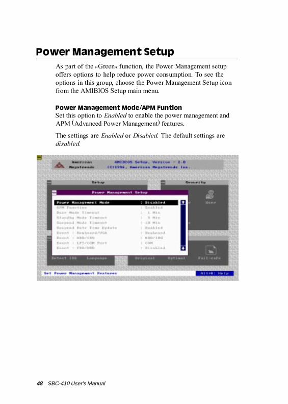
Power Management SetupAs part of the "Green" function, the Power Management setupoffers options to help reduce power consumption. To see theoptions in this group, choose the Power Management Setup iconfrom the AMIBIOS Setup main menu.
Power Management Mode/APM FuntionSet this option to Enabled to enable the power management andAPM (Advanced Power Management) features.
The settings are Enabled or Disabled. The default settings aredisabled.

Chapter 3 AMIBIOS setup 49
The settings are No or Yes. The Optimal and Fail-Safe defaultsettings are Yes.
PCI/PnP SetupPCI/PnP Setup options are displayed by choosing the PCI/PnPSetup icon from the AMIBIOS Setup main menu. All PCI/PnPSetup options are described in this section.
Plug and Play Aware OSSet this option to Yes if the operating system installed in thecomputer is Plug and Play-aware. AMIBIOS only detects andenables PnP ISA adapter cards that are required for system boot.The Windows 95 operating system detects and enables all otherPnP-aware adapter cards. Windows 95 is PnP-aware. Set this optionto No if the operating system (such as DOS, OS/2, Windows 3.x)does not use PnP.
You must set this option correctly or PnP-aware adapter cardsinstalled in your computer will not be configured properly.
50 SBC-410 User's Manual
PCI Latency Timer (in PCI Clocks)This option sets latency of all PCI devices on the PCI bus. Thesettings are in units equal to PCI clocks. The settings are 32, 64,96, 128, 160, 192, 224, or 248. The Optimal and Fail-Safe defaultsettings are 64.
VGA Locate BusThis option allows you to select VGA bus. The setting is PCI andISA (Default).
CPU to PCI Write BufferThis option sets the write buffer between CPU and PCI bus. Thedefault setting is Enabled.
Byte MergeSet this option to Enabled to specify the IDE contraller totransmit data with byte merge. This will improve the datatransimitting performonce.
PCI IDE BusMasterSet this option to Enabled to specify that the IDE controller on thePCI local bus has bus mastering capability. The settings areDisabled or Enabled. The Optimal and Fail-safe default settings areDisabled.
Offboard PCI IDE CardThis option specifies if an offboard PCI IDE controller adapter cardis used in the computer. You must also specify the PCI expansionslot on the motherboard where the offboard PCI IDE controlleron the motherboard is automatically disabled. The settings areAuto, Slot1, Slot2, Slot3, Slot4, Slot5 or Slot6.
If Auto is selected, AMIBIOS automatically determines the correctsetting for this option. The Optionmal and Fail-Safe default settingsare Auto.

Chapter 3 AMIBIOS setup 51
PCI Slot1 IRQ PriorityPCI Slot2 IRQ PriorityPCI Slot3 IRQ PriorityPCI Slot4 IRQ Priority
This option sets PCI slot IRQ priority.
The selectable settings are Auto,3,4,5,7,9,10,11. The default setting is Auto.
IRQ3IRQ4IRQ5IRQ7IRQ9IRQ10IRQ11IRQ14IRQ15
These options specify the bus that the named interrupt requestlines (IRQs) are used on. These options allow you to specify IRQsfor use by legacy ISA adapter cards.
These options determine if AMIBIOS should remove an IRQ fromthe pool of available IRQs passed to BIOS configurable devices.The available IRQ pool is determined by reading the ESCDNVRAM. If more IRQs must be removed from the pool, the enduser can use these PCI/PnP Setup options to remove the IRQ byassigning the option to the ISA/EISA setting. Onboard I/O isconfigurable by AMIBIOS. The IRQs used by onboard I/O areconfigured as PCI/PnP.
The settings are PCI/PnP or ISA/EISA. The Optimal and Fail-Safedefault settings are PCI/PnP.

52 SBC-410 User's Manual
Reserved Memory SizeThis option specifies the size of the memory area reserved forlegacy ISA adapter cards.
The settings are Disabled, 16K, 32K, or 64K and Fail-Safe defaultsettings are Disabled.
Reserved Memory AddressThis option specifies the beginning address (in hex) of the reservedmemory area. The specified ROM memory area is reserved for useby legacy ISA adapter cards.
The settings are C0000, C4000, C8000, CC000, D0000, D4000,D8000, or DC000.

Chapter 3 AMIBIOS setup 53
Onboard FDCThis option enables the floppy drive controller on the motherboard.The settings are Auto, Enabled or Disabled.
Onboard Serial Port 1This option enables serial port 1 on the motherboard andspecifies the base I/O port address for serial port 1.
The settings are Auto, Disabled, 3F8h, 3E8h, 2E8h,2F8h. TheFail-Safe default setting is Auto.
Peripheral SetupPeripheral Setup options are displayed by choosing the Peripher-al Setup icon from the AMIBIOS Setup main menu. All Peripher-al Setup options are described in this section:
54 SBC-410 User's Manual
Onboard Serial Port2This option enables serial port 2 on the motherboard and specifiesthe base I/O port address for serial port 2. The settings are Auto.Disabled, 3F8h, 2F8h, 3E8h, 2E8h. The Fail-Safe default setting isAuto.
Onboard Parallel PortThis option enables the parallel port on the motherboard andspecifies the parallel port base I/O port address. The settings areAuto, disabled, 378, 278, 3BC. The Fail-Safe default setting isAuto.
Parallel Port ModeThis option specifies the parallel port mode. ECP and EPP areboth bidirectional data transfer sechemes that adhere to the IEEEP1284 specification. The settings are:
Setting DescriptionNormal The normal parallel port mode is used. This is the
default setting.
EPP The parallel port can be used with devices thatadhere to the Enhanced Parallel Port (EPP) specifi-cation. EPP uses the exiting parallel port signals toprovide asymmetric bidirectional data transferdriven by the host device.
ECP The parallel port can be used with devices thatadhere to the Extended Capabilities Port (ECP)specification. ECP uses the DMA protocol toachieve transfer rates of approximately 2.5 Mbs.ECP provides symmetric bidirectional communla-tions.

Chapter 3 AMIBIOS setup 55
Parallel Port DMA ChannelThis option is only available if the setting for the Parallel PortMode option is ECP.
The settings are 0 (channel 0) ,1 (channel 1) , 3 (channel 3) .
Parallel Port IRQIRQ7 is used for the Parallel Port(LPT 1). The IRQ can be changedto IRQ5.
Onboard IDEThis option specifies the onboard IDE controller channels that willbe used. The settings are Primary, Both, or Disabled.

56 SBC-410 User's Manual
UtilityThe following icons appear in this section:
Detect IDE:If drive C: is an IDE drive, the hard disk drive parameters fordrive C: are automatically detected and reported to the Hard DiskDrive C: screen in Standard Setup, so you can easily configuredrive C:. Drive D and CD-ROM could also be automaticallydetected and reported to screen if drive D and CD-ROM are IDEdrives.
Language:The default setting is English.

Chapter 3 AMIBIOS setup 57
SecurityThe following icons appear in this section:
AMIBIOS Setup has an optional password feature. The systemcan be configured so that all users must enter a password everytime the system boots or when AMIBIOS Setup is executed. Youcan either set a Supervisor password or a User password. Thefollowing screen appears when you select the password icon.
AMIBIOS password support

58 SBC-410 User's Manual
The following screen appears when you select the password icon
You can enter a password by:
typing the password on the keyboard
selecting each letter via the mouse
selecting each letter via the pen stylus (pen access must becustomized for each specific hardware platform.)
Setting a PasswordThe password check option is enabled in Advanced Setup bychoosing either Always or Setup. Here, you determine thepassword to be used. The password is stored in CMOS RAM.
To assign a password,
1. Enter a 1-6 character password. The password does notappear on the screen when typed.
2. Retype the password when prompted by AMIBIOS.
A message box will appear when the password is confirmed.
Keep a record of the password. If you forget the password, youmust drain CMOS RAM and reconfigure the system.

Chapter 3 AMIBIOS setup 59
Changing a password1. Select the Supervisor or User icon from the Security section
of the AMIBIOS Setup main menu.
2. Enter the password and press <ENTER>. The screen does notdisplay the characters entered.
3. After the new password is entered, retype the new password asprompted and press <ENTER>.
If the password confirmation is incorrect, an error messageappears. If the new password is entered without error, press<ESC> to return to the AMIBIOS setup Main Menu. The pass-word is stored in CMOS RAM after AMIBIOS Setup completes.The next time the system boots, you are prompted for thepassword if the password function is present and is enabled.
Anti-virus
Select the Anti-virus icon from the Security section of theAMIBIOS Setup main menu. AMIBIOS issues a warning when anyprogram (or virus) issues a Disk format command or attempts towrite to the boot sector of the hard disk drive. The settings areEnabled or Disabled.
If enabled, the following appears when a write is attempted to theboot sector. You may have to type N several times to prevent theboot sector write.
Boot Sector Wr ite !!!
Possible VIRUS: Conti nue (Y/N)? _

60 SBC-410 User's Manual
The following is displayed after any attempt to format anycylinder, head, or sector of any hard disk drive via the BIOS INT13 Hard Disk Drive Service:
Format!!!Possible VIRUS: Continue (Y/N)? _
DefaultThe icons in this section permit you to select a group of settingsfor all AMIBIOS Setup options. Not only can you use these iconsto quickly set system configuration parameters, you can alsochoose a group of settings that have a better chance of workingwhen the system is having configuration-related problems.
Original
Choose the Original icon to return to the system configurationvalues present in AMIBIOS Setup when you first begin thisWinBIOS Setup session.
Optimal
You can load the optimal default settings for the AMIBIOS Setupoptions by selecting the Optimal icon. The Optimal defaultsetting is the best-case values that could optimize system

Chapter 3 AMIBIOS setup 61
performance. If CMOS RAM is corrupted, the Optimal settingsare loaded automatically.
Fail-Safe
You can load the Fail-Safe AMIBIOS Setup options settings byselecting the Fail-Safe icon.
The Fail-Safe setting provides the most stable settings, thoughthey do not provide optimal performance. Use this option as adiagnostic aid if the system is behaving erratically.
Exiting AMIBIOSYou can exit AMIBIOS by pressing the <ESC> key while in theAMIBIOS main menu screen.
The following screen appears:
Select the option you desire, and the system will continue its bootup sequence.

62 SBC-410 User's Manual

Appendix A Watchdog Timer Demo Program 63
AWatchdog TimerDemo Program
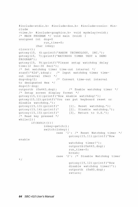
The following demo program illustratesthe programming steps required to enable,set, and disable the watchdog timer.
AP
PE
ND
IX
64 SBC-410 User's Manual
#include<stdio.h> #include<dos.h> #include<conio> #in-clude<time.h> #include<graphics.h> void mydelay(void);/* MAIN PROGRAM */ void main (void) {unsigned int dog=0
run_time=0; char inkey;
clrscr();gotoxy(15, 6);printf("AAEON TECHNOLOGY, INC.");gotoxy(15, 7);printf("WATCHDOG TIMER TEST & DEMOPROGRAM");gotoxy(15, 9);printf("Please setup watchdog delaytime:(2 Sec-30 Sec)");/* Set watchdog timer time-out interval */scanf("%2d",&dog); /* Input watchdog timer time-out interval (Sec) */dog=dog/2; /* Convert time-out intervalto designated Hex */dog=15-dog;outportb (0x443,dog); /* Enable watchdog timer *//* Setup screen display format */gotoxy(15,11);printf("Now enable watchdog!");gotoxy(15,12);printf("You can put keyboard reset ordisable watchdog.");gotoxy(15,13);printf(" [1]. Reset watchdog.");gotoxy(15,14);printf(" [2]. Disable watchdog.");gotoxy(15,15);printf(" [3]. Return to O.S.");/* Read key pressed */while(1){
if(kbhit()){inkey=getch();switch(inkey){
case '1': /* Reset Watchdog timer */gotoxy(15,11);printf("Now
enablewatchdog timer!");outportb(0x443,dog);run_time=0;break;
case '2': /* Disable Watchdog timer* /
gotoxy(15,12);printf("Nowdisable watchdog timer!");outportb (0x80,dog);return;

Appendix A Watchdog Timer Demo Program 65
default : break;}
}mydelay();run_time=run_time+1;
/* Display time elapsed */gotoxy(45,11);printf(%2d.%1d sec",run_time/10,run_time%10);
}}/* USER FUNCTION LIBRARY */ void mydelay(void) /*Delay program: */ /* Delay 109.89ms (18.2Hz*2) */{
clock_t start,end;start=clock();end=start;while((end-start)<2){ end=clock();}
}

66 SBC-410 User's Manual
Appendix B Installing PC/104 Modules 67
AP
PE
ND
IXBInstalling PC/104Modules
This appendix gives instructions forinstalling PC/104 module.

68 SBC-410 User's Manual
Installing PC/104 modulesThe SBC-410's PC/104 connectors give you the flexibility toattach PC/104 expansion modules. These modules perform thefunctions of traditional plug-in expansion cards, but save spaceand valuable slots. Modules include:
• PCM-3600 FAX/Modem Module• PCM-3420 Fast SCSI-2 Module• PCM-3200 Sound Module• PCM-3810 Solid State Disk Module• PCM-3820 High Density Flash Disk Module• PCM-3115 PCMCIA Module (two slots)• PCM-3610 Isolated RS-232 and RS-422/485 Module• PCM-3660 Ethernet Module• PCM-3718 30 KHz A/D Module• PCM-3724 48-channel DIO Module• PCM-3910 Breadboard ModuleTo install these modules on the SBC-400 is a quick and simpleoperation. The following steps show how to mount the PC/104modules:
Step 1 Remove the SBC-410 from your system payingparticular attention to the safety instructions alreadymentioned above.
Step 2 Make any jumper or link changes required to theCPU card now. Once the PC/104 module is mountedyou may have difficulty in accessing these.
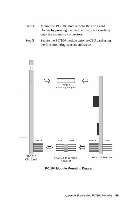
Step 3 Normal PC/104 modules have "male" connectorsand mount directly onto the main card. However,for reasons that ensure better bus matching, theconnectors on the SBC-410 and the PC/104 moduleare both "female". For this reason you need to plug-in a "male-male" adapter connecter (included withthe SBC-410). Please refer to the following PC/104module mounting diagram on the following page.After this is in place you then have the correctmounting connector to accept your PC/104 module.
Appendix B Installing PC/104 Modules 69
Step 4 Mount the PC/104 module onto the CPU card.Do this by pressing the module firmly but carefullyonto the mounting connectors.
Step 5 Secure the PC/104 module onto the CPU card usingthe four mounting spacers and srews.
PC/104 Module Mounting Diagram
PC/104 ModuleSBC-350ACPU Card
PC/104 Mount ingAdaptor
PC/104Mount ing Suppor t
MaleFemale Male Female Male
SBC-410CPU Card

70 SBC-410 User's Manual
PC/104 module dimensions (inches ±5±5±5±5±5 %)
3 .500
3 .7753 .575
0 .200
0
00 .200
3 .5503 .350
0 .200
3 .575
3 .250


