SBE 46 LCD Display Box User’s Manual Sea-Bird Electronics, Inc. 1808 136 th Place NE Bellevue, Washington 98005 USA Tel: 425/643-9866 Manual Version #001, 4/30/00 Fax:425/643-9954 Firmware Version 1.1
Transcript
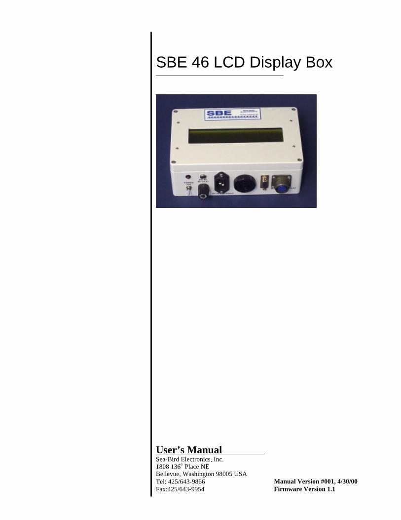
SBE 46 LCD Display Box
User’s ManualSea-Bird Electronics, Inc.1808 136th Place NEBellevue, Washington 98005 USATel: 425/643-9866 Manual Version #001, 4/30/00Fax:425/643-9954 Firmware Version 1.1
2
Limited Liability StatementExtreme care should be exercised when using or servicing this equipment. It should be used or servicedonly by personnel with knowledge of and training in the use and maintenance of oceanographicelectronic equipment.
SEA-BIRD ELECTRONICS, INC. disclaims all product liability risks arising from the use or servicingof this system. SEA-BIRD ELECTRONICS, INC. has no way of controlling the use of this equipmentor of choosing the personnel to operate it, and therefore cannot take steps to comply with lawspertaining to product liability, including laws which impose a duty to warn the user of any dangersinvolved in operating this equipment. Therefore, acceptance of this system by the customer shall beconclusively deemed to include a covenant by the customer to defend, indemnify, and hold SEA-BIRDELECTRONICS, INC. harmless from all product liability claims arising from the use or servicing ofthis system.
Table of Contents
3
Table of Contents
Table of Contents ................................................................................. 3
Section 1: Introduction ........................................................................ 4About this Manual ............................................................................................. 4How to Contact Sea-Bird .................................................................................. 4Quick Start ........................................................................................................ 4Unpacking the SBE 46 ...................................................................................... 5
Section 2: Description of the SBE 46 .................................................. 6System Description ........................................................................................... 6Data Format....................................................................................................... 7SBE 46 Specifications ....................................................................................... 8SBE 46 Dimensions in millimeters (inches)...................................................... 9
Section 3: Programming, Testing, and Operating the SBE 46....... 10Removing Lid and Checking Jumpers ............................................................ 10Programming and Testing the SBE 46 ............................................................ 11
Set-Up ...................................................................................................... 11Program and Test ..................................................................................... 12
Mounting the SBE 46 (optional) ..................................................................... 16Setting Up the Instrument................................................................................ 17Operating the SBE 46...................................................................................... 18
Section 1: IntroductionThis section includes contact information, Quick Start procedure, and photosof a standard SBE 46 shipment.
About this ManualThis manual is to be used with the SBE 46 LCD Display Box. It is organizedto guide the user from installation through operation and data display. We’veincluded detailed specifications, command descriptions, testing and operatingprocedures, and helpful notes throughout the manual.
A feedback questionnaire is located at the end of the manual. Please take a fewmoments to let us know how you like the manual contents and format. Eitheruse the form or e-mail comments to [email protected]. Your feedbackwill help us provide you with a complete and comprehensive User’s Manual.
How to Contact Sea-BirdSea-Bird Electronics, Inc.1808 136th Place NortheastBellevue, Washington 98005 USA
Business hours:Monday-Friday, 0800 to 1800 Pacific Standard Time
(1600 to 0200 Universal Time)Except from April to October, when we are on ‘summer time’
(1500 to 0100 Universal Time)
Quick StartFollow these steps to get a Quick Start using the SBE 46.Section 3: Programming, Testing, and Operating the SBE 46 provides step-by-step details for performing each task:
1. Program SBE 46 (see Programming and Testing the SBE 46 in Section 3):A. Connect PC and power supply to SBE 46.B. Set PCB jumpers — J1: pins 2 and 3; J3: on, J2: on if powered with
internal battery.C. Configure SBE 46 as an SBE 37 in SEATERM.D. Turn on power toggle switch.E. Send desired commands to program SBE 46.
2. Set up Instrument (see Setting Up the Instrument in Section 3):A. Set instrument baud rate to same rate as SBE 46.B. Set instrument to wake up and start sampling when power is applied
(if applicable), or start sampling now or at a delayed date and time.
3. Operate SBE 46 (see Operating the SBE 46 in Section 3):A. Set PCB jumpers — J1: pins 2 and 3 for SBE 11plus V2, pins 1 and 2
for all other instruments; J3: off.B. Connect SBE 46 to instrument.C. Connect power supply to SBE 46 and turn on power toggle switch.
Section 1: Introduction
5
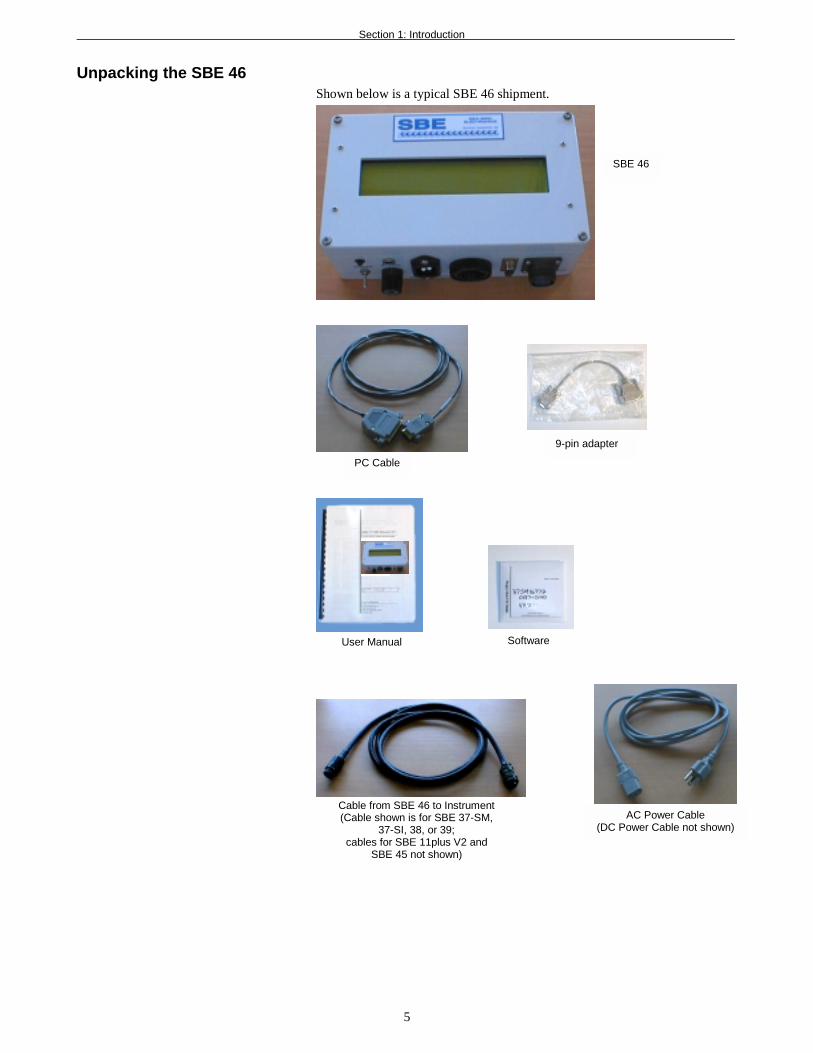
Unpacking the SBE 46Shown below is a typical SBE 46 shipment.
Software
9-pin adapter
SBE 46
User Manual
Cable from SBE 46 to Instrument(Cable shown is for SBE 37-SM,
37-SI, 38, or 39;cables for SBE 11plus V2 and
SBE 45 not shown)
AC Power Cable(DC Power Cable not shown)
PC Cable
Section 2: Description of the SBE 46
6
Section 2: Description of the SBE 46This section describes the functions and features of the SBE 46, includingspecifications and dimensions.
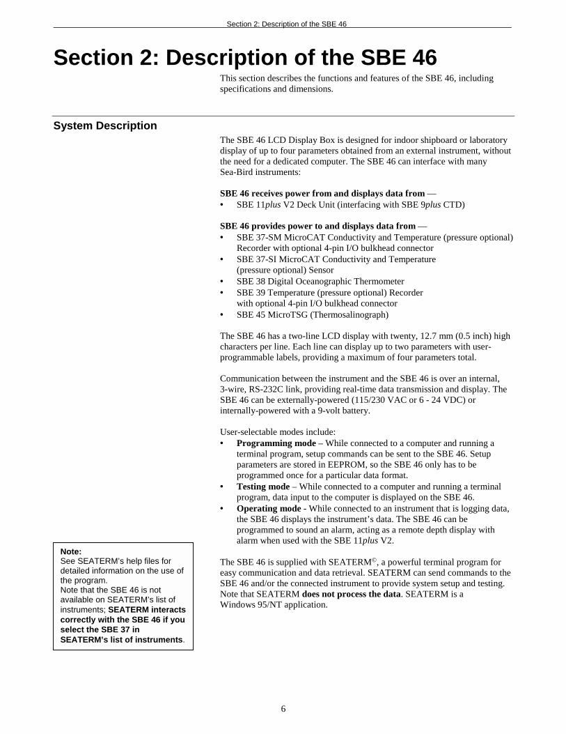
System DescriptionThe SBE 46 LCD Display Box is designed for indoor shipboard or laboratorydisplay of up to four parameters obtained from an external instrument, withoutthe need for a dedicated computer. The SBE 46 can interface with manySea-Bird instruments:
SBE 46 receives power from and displays data from —• SBE 11plus V2 Deck Unit (interfacing with SBE 9plus CTD)
SBE 46 provides power to and displays data from —• SBE 37-SM MicroCAT Conductivity and Temperature (pressure optional)
Recorder with optional 4-pin I/O bulkhead connector• SBE 37-SI MicroCAT Conductivity and Temperature
(pressure optional) Sensor• SBE 38 Digital Oceanographic Thermometer• SBE 39 Temperature (pressure optional) Recorder
with optional 4-pin I/O bulkhead connector• SBE 45 MicroTSG (Thermosalinograph)
The SBE 46 has a two-line LCD display with twenty, 12.7 mm (0.5 inch) highcharacters per line. Each line can display up to two parameters with user-programmable labels, providing a maximum of four parameters total.
Communication between the instrument and the SBE 46 is over an internal,3-wire, RS-232C link, providing real-time data transmission and display. TheSBE 46 can be externally-powered (115/230 VAC or 6 - 24 VDC) orinternally-powered with a 9-volt battery.
User-selectable modes include:• Programming mode – While connected to a computer and running a
terminal program, setup commands can be sent to the SBE 46. Setupparameters are stored in EEPROM, so the SBE 46 only has to beprogrammed once for a particular data format.
• Testing mode – While connected to a computer and running a terminalprogram, data input to the computer is displayed on the SBE 46.
• Operating mode - While connected to an instrument that is logging data,the SBE 46 displays the instrument’s data. The SBE 46 can beprogrammed to sound an alarm, acting as a remote depth display withalarm when used with the SBE 11plus V2.
Note:See SEATERM’s help files fordetailed information on the use ofthe program.Note that the SBE 46 is notavailable on SEATERM’s list ofinstruments; SEATERM interactscorrectly with the SBE 46 if youselect the SBE 37 inSEATERM’s list of instruments.
Section 2: Description of the SBE 46
7
Data FormatThe SBE 46 displays up to four parameters from the connected instrument.When the SBE 46 receives a line of data (data from one sample) from theconnected instrument, it:1. Reads the data,2. Breaks the data into parameters, and3. Assigns each parameter to a location on the LCD display.
The SBE 46 defines any combination of spaces, tabs, and commas as a breakbetween two parameters. For example, each of the following is a breakbetween two parameters:• a comma• a space• a comma followed by a space
If the SBE 46 detects date and time (by checking for two colons [:] in thedata), it ignores the date and displays the time.
Following is the SBE 46’s output data format. Note that the SBE 46 insertsone space between the first and second parameters on a line:
• One Parameter (data1)Top line of display: P1LABEL=data1
• Two Parameters (data1, data2)Top line of display: P1LABEL=data1Bottom line of display: P2LABEL=data2
• Three Parameters (data1, data2, data3)Top line of display: P1LABEL=data1 P2LABEL=data2Bottom line of display: P3LABEL=data3
• Four Parameters (data1, data2, data3, data4)Top line of display: P1LABEL=data1 P2LABEL=data2Bottom line of display: P3LABEL=data3 P4LABEL=data4
Example:An SBE 37-SI is set up to output temperature, conductivity, date, andsalinity. When connected to a computer, the SBE 37-SI data lookslike this in SEATERM:
The SBE 46 is programmed with P1LABEL=T, P2LABEL=C,P3LABEL=S, P4LABEL=TM.
When connected to the SBE 46, the SBE 37-SI data looks like this onthe SBE 46 display:
T=20.7977 C=0.00005S=0.0103 TM=10:09:56
Note:P1LABEL, P2LABEL, P3LABEL,and P4LABEL are user-programmable data labels.
Section 2: Description of the SBE 46
8
SBE 46 Specifications
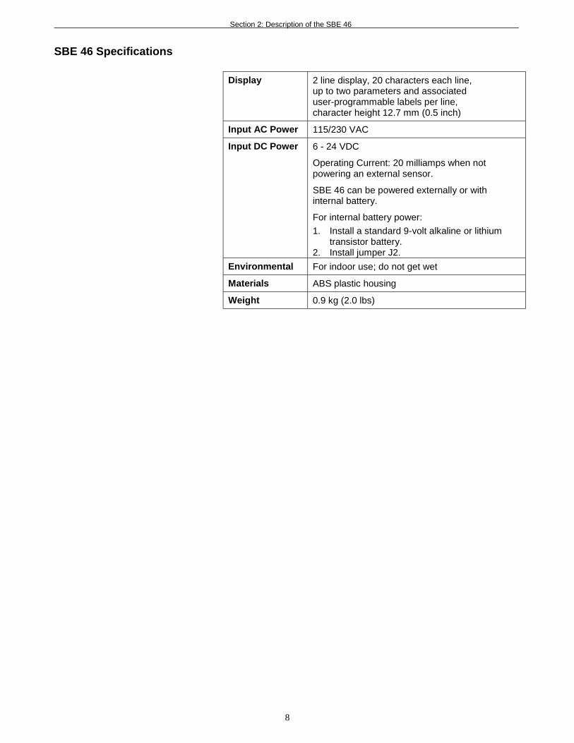
Display 2 line display, 20 characters each line,up to two parameters and associateduser-programmable labels per line,character height 12.7 mm (0.5 inch)
Input AC Power 115/230 VAC
Input DC Power 6 - 24 VDC
Operating Current: 20 milliamps when notpowering an external sensor.
SBE 46 can be powered externally or withinternal battery.
For internal battery power:
1. Install a standard 9-volt alkaline or lithiumtransistor battery.
2. Install jumper J2.
Environmental For indoor use; do not get wet
Materials ABS plastic housing
Weight 0.9 kg (2.0 lbs)
Section 2: Description of the SBE 46
9
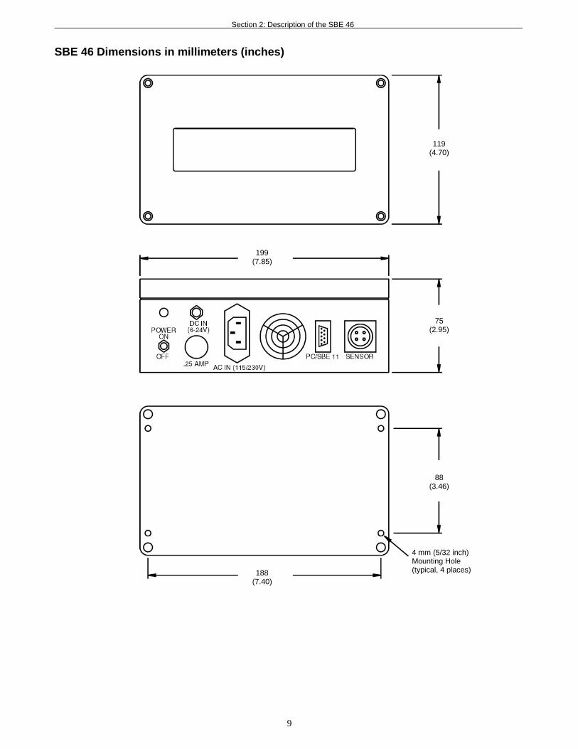
SBE 46 Dimensions in millimeters (inches)
119(4.70)
199(7.85)
75(2.95)
88(3.46)
188(7.40)
4 mm (5/32 inch)Mounting Hole(typical, 4 places)
Section 3: Programming, Testing, and Operating the SBE 46
10
Section 3: Programming, Testing, andOperating the SBE 46
This section describes jumper settings, and programming, testing, andoperating the SBE 46.
Removing Lid and Checking JumpersThe SBE 46’s Printed Circuit Board (PCB) has several jumpers that controlhow the SBE 46 is powered and responds. Remove the SBE 46 lid to check thejumper settings as described below:
1. Remove the four 4 mm, recessed, self-retaining, Phillips-head screwssecuring the lid to the housing body. Do not remove the four smallerscrews in the lid – these secure the LCD to the lid.
2. Remove the lid, being careful not to pull out the ribbon cable.
3. See the drawing below for jumper descriptions and locations. Movejumpers as directed in the programming, testing, and operating proceduresin the following sections.
4. When done moving/checking jumpers, re-secure the lid to the housingbody with the four Phillips-head screws.
CAUTION:Avoid getting anything on thePCB, which can be damaged bywater or other materials.
Pin position on J1:• Pins 1 and 2 –
SBE 37-SM, SBE 37-SI,SBE 38, SBE 39, or SBE 45
• Pins 2 and 3 –SBE 11plus V2 or computer
J1
3
2
1
Pin position on J3:• Jumper on – Programming mode• Jumper off –
Testing or Operating mode
J3
2 1
Pin position on J2:• Jumper on – Internally powered
(battery)• Jumper off – Externally powered
J2
2 1
Install 9 voltalkaline or lithiumtransistor battery
for internal batteryoperation
Remove screw(typical, 4 places)
Do not remove(typical, 4 places)
Section 3: Programming, Testing, and Operating the SBE 46
11
Programming and Testing the SBE 46Programming and testing will set up the SBE 46 and verify that it works, priorto operation with an instrument.
Set-Up1. If not already installed, install SEATERM on your computer using the
supplied software:A. Insert Disk 1 in your floppy disk drive.B. Double click on Setup.exe.C. Follow the dialog box directions to install the software.(Note: It is possible to use the SBE 46 without SEATERM by sendingdirect commands from a dumb terminal or terminal emulator, such asWindows HyperTerminal.)
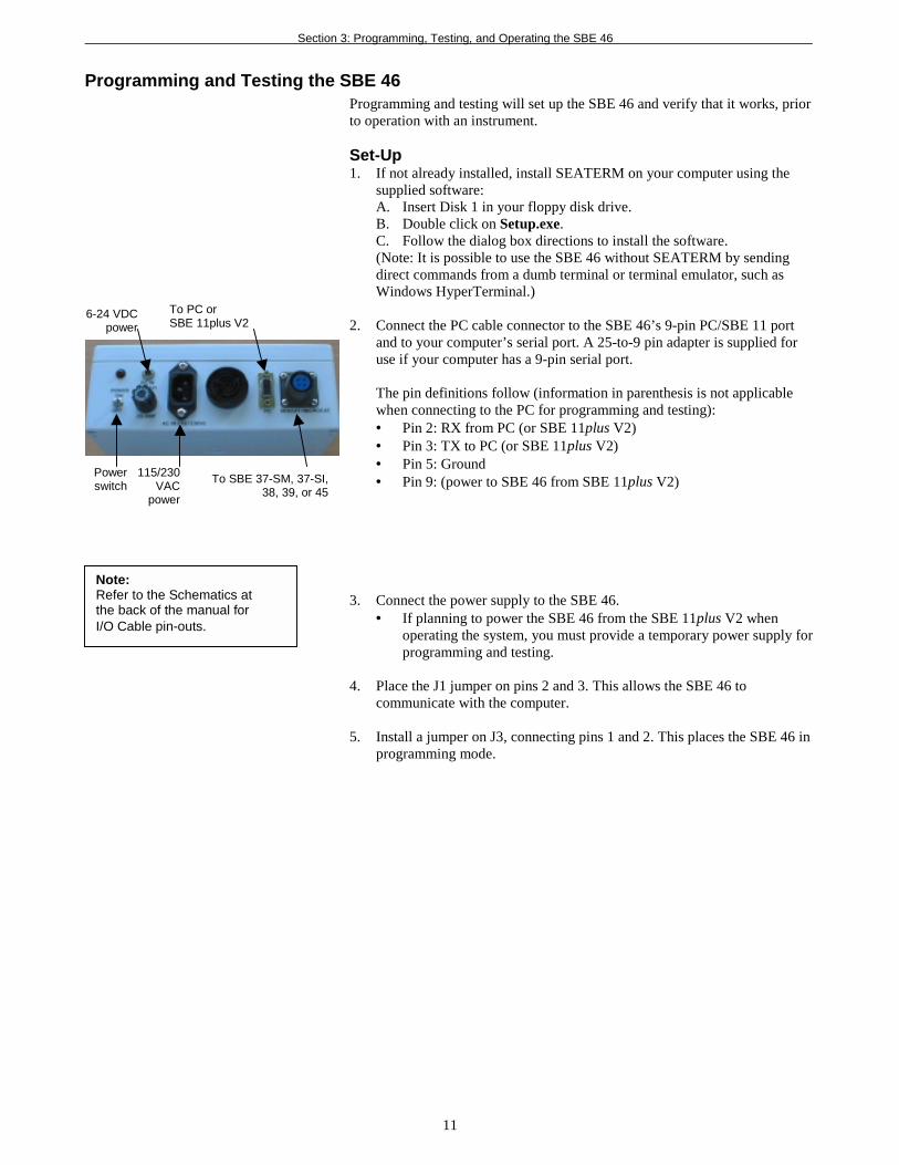
2. Connect the PC cable connector to the SBE 46’s 9-pin PC/SBE 11 portand to your computer’s serial port. A 25-to-9 pin adapter is supplied foruse if your computer has a 9-pin serial port.
The pin definitions follow (information in parenthesis is not applicablewhen connecting to the PC for programming and testing):• Pin 2: RX from PC (or SBE 11plus V2)• Pin 3: TX to PC (or SBE 11plus V2)• Pin 5: Ground• Pin 9: (power to SBE 46 from SBE 11plus V2)
3. Connect the power supply to the SBE 46.• If planning to power the SBE 46 from the SBE 11plus V2 when
operating the system, you must provide a temporary power supply forprogramming and testing.
4. Place the J1 jumper on pins 2 and 3. This allows the SBE 46 tocommunicate with the computer.
5. Install a jumper on J3, connecting pins 1 and 2. This places the SBE 46 inprogramming mode.
Note:Refer to the Schematics atthe back of the manual forI/O Cable pin-outs.
115/230VAC
power
6-24 VDCpower
To PC orSBE 11plus V2
To SBE 37-SM, 37-SI,38, 39, or 45
Powerswitch
Section 3: Programming, Testing, and Operating the SBE 46
12
Program and TestProceed as follows:1. On the computer, double click on the SEATERM icon. If this is the first
time the program is used, the configuration dialog box appears:
Select the instrument type (SBE 37) and the computer COM port forcommunication with the SBE 46. Click OK.
2. The main screen looks like this:
• Menus – Contains tasks and frequently executed instrument commands.• Toolbar – Contains buttons for frequently executed tasks and instrument
commands. All tasks and commands accessed through the Toolbar arealso available in the Menus. To display or hide the Toolbar, select ViewToolbar in the View menu. Grayed out Toolbar buttons are not applicable.
• Command/Data Echo Area – Echoes a command that was executed usinga Menu or Toolbar button, as well as the instrument’s response.Additionally, a command can be manually typed in this area, from theavailable commands for the instrument. Note that the SBE 46 must bepowered up for it to respond to a command.
• Status bar – Provides status information. To display or hide the Status bar,select View Status bar in the View menu.
Note:Once the SBE 46 is configured andpowered up (Steps 3 and 4 below),to update the Status bar:• on the Toolbar, click Status; or• from the Utilities menu, select
Instrument Status.SEATERM sends the statuscommand, which displays in theCommand/Data Echo Area, andupdates the Status bar.
Status bar
Menus
Command/Data Echo Area
Toolbar
InstrumentComputerCOM port
InstrumentEPROM version
Baud rate, data bits,stop bits, and parity
Capture to file status – grayedout if not capturing
Notes:1. The SBE 46 is not available
in the list of InstrumentTypes. Select the SBE 37as the instrument type.
2. See SEATERM’s help filesfor detailed information onthe use of the program.
Notes:Program the SBE 46 using acomputer running SEATERM ora dumb terminal or terminalemulator, such as WindowsHyperTerminal.
Section 3: Programming, Testing, and Operating the SBE 46
13
Following are the Toolbar keys applicable to the SBE 46:
ToolbarKeys
Description EquivalentCommand*
Status Display instrument status. DSCapture Capture instrument responses on screen to
file. File has .CAP extension. Press Captureagain to turn off capture. Capture statusdisplays in Status bar.
—
Disconnect Free computer COM port used tocommunicate with SBE 46. COM port canthen be used by another program. Note thatSBE 46 must be connected to COM port fordata to be obtained.
—
*See Command Descriptions.
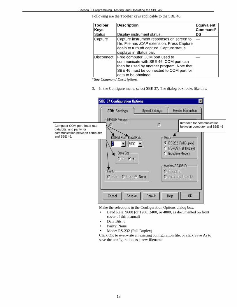
3. In the Configure menu, select SBE 37. The dialog box looks like this:
Make the selections in the Configuration Options dialog box:• Baud Rate: 9600 (or 1200, 2400, or 4800, as documented on front
cover of this manual)• Data Bits: 8• Parity: None• Mode: RS-232 (Full Duplex)Click OK to overwrite an existing configuration file, or click Save As tosave the configuration as a new filename.
Computer COM port, baud rate,data bits, and parity forcommunication between computerand SBE 46.
Interface for communicationbetween computer and SBE 46
Section 3: Programming, Testing, and Operating the SBE 46
14
4. Turn on the power toggle switch on the SBE 46. The SBE 46 displays theresult of the status (DS) command:
SBE-46 LCD DISPLAY V 1.1alarm disabledp1 label = t = (default for P1LABEL is t)p2 label = c = (default for P2LABEL is c)p3 label = p = (default for P3LABEL is p)p4 label = s = (default for P4LABEL is s)S>This shows that correct communications between the computer and theSBE 46 has been established. If the system does not respond as shown:• Toggle the power switch again to attempt to establish
communications.• Verify that the SBE 37 was selected in the Configure menu and the
settings were entered correctly in the Configuration Optionsdialog box.
• Check power cabling and cabling between the computer and SBE 46.
5. Send the desired commands, described below. When entering commands:• Input commands in upper or lower case letters and register commands
by pressing the Enter key.• The SBE 46 sends ? CMD if an invalid command is entered.• If the system does not return an S> prompt after executing a
command, press the Enter key to get the S> prompt.
Command DescriptionsDS Display operating status.
Equivalent to Status button on Toolbar.
BAUD=x x= baud rate (1200, 2400, 4800, or 9600).Default 9600.
ENABLEALARM=x x=Y: Sound alarm when data scan contains ana or A character. This allows the SBE 46 to actas a remote depth display with alarm whenused with the SBE 11plus V2.
x=N (default): Do not sound alarm when datascan contains an a or A character.
P1LABEL=str str = data label 1 (default t).
P2LABEL=str str = data label 2 (default c).
P3LABEL=str str = data label 3 (default p).
P4LABEL=str str = data label 4 (default s).
Note:str can be any combination ofcharacters with a maximum lengthof 10. Spaces can be entered at thebeginning of the string to make thedata labels on each line of the displayline up.
Section 3: Programming, Testing, and Operating the SBE 46
15
6. Test the programming as follows:A. Remove the jumper on J3. This takes the SBE 46 out of programming
mode and into testing/operating mode. The SBE 46 display shouldlook like this:SBE-46 LCD DISPLAYV 1.1
B. On the computer, type the entries shown below and hit the Enter key.View the responses on the SBE 46:
Section 3: Programming, Testing, and Operating the SBE 46
16
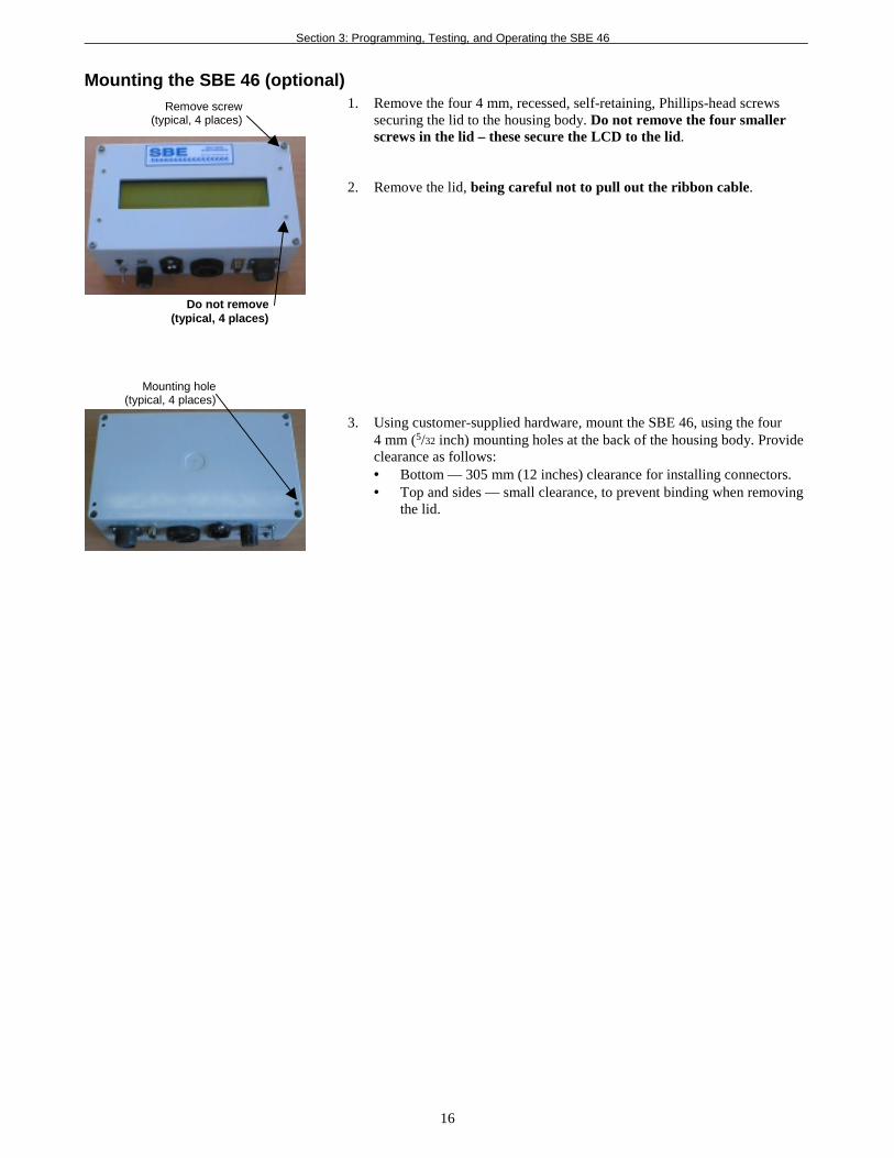
Mounting the SBE 46 (optional)1. Remove the four 4 mm, recessed, self-retaining, Phillips-head screws
securing the lid to the housing body. Do not remove the four smallerscrews in the lid – these secure the LCD to the lid.
2. Remove the lid, being careful not to pull out the ribbon cable.
3. Using customer-supplied hardware, mount the SBE 46, using the four4 mm (5/32 inch) mounting holes at the back of the housing body. Provideclearance as follows:• Bottom — 305 mm (12 inches) clearance for installing connectors.• Top and sides — small clearance, to prevent binding when removing
the lid.
Remove screw(typical, 4 places)
Do not remove(typical, 4 places)
Mounting hole(typical, 4 places)
Section 3: Programming, Testing, and Operating the SBE 46
17
Setting Up the InstrumentThis section describes the setup of the instrument (SBE 11plus V2, 37-SM,37-SI, 38, 39, or 45) required for it to interface with the SBE 46. See theappropriate instrument manual for details on connecting the instrument tothe computer, running the terminal program, and a complete list ofinstrument commands.
1. Set the instrument baud rate to the same rate as the SBE 46.
2. Set the instrument to wake up and start sampling when power is applied(applicable to the following instruments):• SBE 37-SI: Set Interface PCB J1 jumper to Autopower position, and
send AUTORUN=Y and SINGLESAMPLE=N commands.• SBE 38: Send AUTORUN=Y command.• SBE 45: Set PCB J1 jumper to Autopower position, and send
AUTORUN=Y and SINGLESAMPLE=N commands.
3. Set the instrument to start sampling now or later(applicable to the SBE 37-SM or 39):• Send the STARTNOW command, or• Send STARTMMDDYY and STARTHHMMSS commands to set
the delayed logging starting date and time. Then send theSTARTLATER command.
Note:You can set up the instrument by:• Connecting it directly to the
computer, as described here, or• Connecting it to the SBE 46,
placing the SBE 46 in operatingmode, and connecting the SBE 46to the computer (not applicable tothe SBE 11plus V2). See Operatingthe SBE 46 below for details.
Section 3: Programming, Testing, and Operating the SBE 46
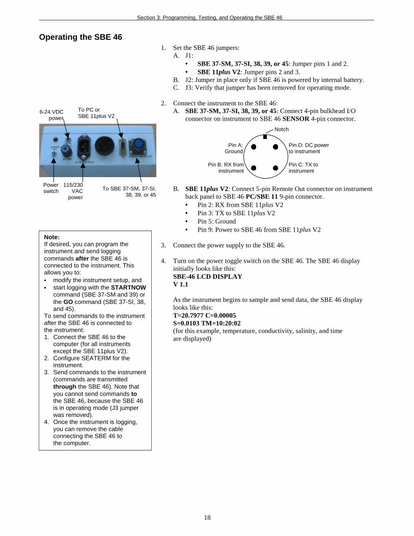
Operating the SBE 461. Set the SBE 46 jumpers:
A. J1:• SBE 37-SM, 37-SI, 38, 39, or 45: Jumper pins 1 and 2.• SBE 11plus V2: Jumper pins 2 and 3.
B. J2: Jumper in place only if SBE 46 is powered by internal battery.C. J3: Verify that jumper has been removed for operating mode.
2. Connect the instrument to the SBE 46:A. SBE 37-SM, 37-SI, 38, 39, or 45: Connect 4-pin bulkhead I/O
connector on instrument to SBE 46 SENSOR 4-pin connector.
B. SBE 11plus V2: Connect 5-pin Remote Out connector on instrumentback panel to SBE 46 PC/SBE 11 9-pin connector.• Pin 2: RX from SBE 11plus V2• Pin 3: TX to SBE 11plus V2• Pin 5: Ground• Pin 9: Power to SBE 46 from SBE 11plus V2
3. Connect the power supply to the SBE 46.
4. Turn on the power toggle switch on the SBE 46. The SBE 46 displayinitially looks like this:SBE-46 LCD DISPLAYV 1.1
As the instrument begins to sample and send data, the SBE 46 displaylooks like this:T=20.7977 C=0.00005S=0.0103 TM=10:20:02(for this example, temperature, conductivity, salinity, and timeare displayed)
115/230VAC
power
6-24 VDCpower
To PC orSBE 11plus V2
To SBE 37-SM, 37-SI,38, 39, or 45
Powerswitch
Pin C: TX toinstrument
Pin A:Ground
Pin D: DC powerto instrument
Pin B: RX frominstrument
Notch
Note:If desired, you can program theinstrument and send loggingcommands after the SBE 46 isconnected to the instrument. Thisallows you to:• modify the instrument setup, and• start logging with the STARTNOW
command (SBE 37-SM and 39) orthe GO command (SBE 37-SI, 38,and 45).
To send commands to the instrumentafter the SBE 46 is connected tothe instrument:1. Connect the SBE 46 to the
computer (for all instrumentsexcept the SBE 11plus V2).
2. Configure SEATERM for theinstrument.
3. Send commands to the instrument(commands are transmittedthrough the SBE 46). Note thatyou cannot send commands tothe SBE 46, because the SBE 46is in operating mode (J3 jumperwas removed).
4. Once the instrument is logging,you can remove the cableconnecting the SBE 46 tothe computer.
18
Glossary
19
GlossaryPCB – Printed Circuit Board.
Scan – One data sample. The data sample may contain primary data(temperature, conductivity, pressure), date and time, and derived variables(such as salinity and sound velocity).
SBE 46 – LCD Display Box for interfacing with:• SBE 11plus V2 Deck Unit,• SBE 37-SM MicroCAT Conductivity and Temperature
(pressure optional) Recorder,• SBE 37-SI MicroCAT Conductivity and Temperature
(pressure optional) Sensor,• SBE 38 Digital Oceanographic Thermometer,• SBE 39 Temperature (pressure optional) Recorder, or• SBE 45 MicroTSG (Thermosalinograph)
SEATERM – Terminal program used to communicate with the SBE 46.SEATERM can send commands to the SBE 46 to provide status display,programming, testing, and capture. SEATERM is a Windows 95/NTapplication. Note that the SBE 46 is not available on SEATERM’s list ofinstruments; SEATERM will interact correctly with the SBE 46 if youselect the SBE 37 in SEATERM’s list of instruments.
Appendix I: Command Summary
20
Appendix I: Command SummaryTo send commands to the SBE 46, the SBE 46 must be in programming mode(J3 jumper on, J1 jumper on pins 2 and 3) and connected to a computerrunning a terminal program (SEATERM, or a dumb terminal or terminalemulator, such as Windows HyperTerminal).
When entering commands:• Input commands in upper or lower case letters and register commands by
pressing the Enter key.• The SBE 46 sends ? CMD if an invalid command is entered.• If the system does not return an S> prompt after executing a command,
Default is 9600.ENABLEALARM=x x= Y: Sound alarm when data scan contains an a or
A character. This allows the SBE 46 to act as aremote depth display with alarm when used withSBE 11plus V2.
x= N (default): Do not sound alarm when data scancontains an a or A character.
P1LABEL=str str = data label 1.P2LABEL=str str = data label 2.P3LABEL=str str = data label 3.P4LABEL=str str = data label 4.
Note:str can be any combination ofcharacters with a maximum lengthof 10. Spaces can be entered at thebeginning of the string to make thedata labels on each line of the displayline up.
80677 PC cable SBE 46 PC/SBE 11connector (9-pin) tocomputer (25-pin)
-
17130 25-pin to 9-pin adapter Connects PC cable to9-pin COM port on computer
-
801217 DC power cable Provides DC power toSBE 46
-
17015 AC power cable Provides AC power toSBE 46
-
Index
22
IndexAAbout Sea-Bird · 4Application Notes · See attachments at end of manual
CCommand Summary · 20Commands
Descriptions · 14, 20Communication Defaults · 13
DData Format · 7Description · 6Dimensions · 9
FFeedback Questionnaire · See attachment at end of manualFormat
Data · 7
GGlossary · 19
IInstrument
Setting Up · 17, 18
JJumpers · 10, 11
MModes · 6, 10Mounting · 16
OOperating · 10, 18
PParts
Photos · 5Replacement · 21
Pin Definitions · 11, 18Programming · 10, 11
QQuick Start · 4
RRemoving Lid · 10Replacement Parts · 21
SSchematics · See attachments at end of manualSEATERM · 6, 11, 12Service Information · See attachment at end of manualSpecifications · 8System Description · 6