National Aeronautics and GRC-CONN-DOC-5022 Rev A Space Administration EFFECTIVE DATE: 04/26/2012 Space Communications and Navigation (SCaN) Testbed Project National Aeronautics and Space Administration John H. Glenn Research Center at Lewis Field, Ohio 44135 SCaN TESTBED PROJECT SCaN Testbed Flight and Ground System Description AUTHORIZED by CM when under FORMAL Configuration Control Date Signature /s/ Robert E. Turk 05/01/2012 Distribution: [ ] NASA (U.S. Gov. Only) [ ] Project Only [ X ] Government and Contractors Availability: [ X ] Public (No Restriction) [ ] Export Controlled [ ] Confidential/ Commercial [ ] Internal Use Only
Transcript
National Aeronautics and GRC-CONN-DOC-5022 Rev A
Space Administration EFFECTIVE DATE: 04/26/2012
Space Communications and Navigation (SCaN) Testbed Project
National Aeronautics and Space Administration
John H. Glenn Research Center at Lewis Field, Ohio 44135
SCaN TESTBED PROJECT
SCaN Testbed Flight and Ground System
Description
AUTHORIZED by CM when under FORMAL Configuration Control
Date Signature
/s/ Robert E. Turk 05/01/2012
Distribution:
[ ] NASA (U.S. Gov. Only) [ ] Project Only [ X ] Government and Contractors
Availability:
[ X ] Public (No Restriction) [ ] Export Controlled [ ] Confidential/ Commercial [ ] Internal Use Only
Space Communications and Navigation (SCaN) Testbed Project
Title: SCaN Testbed Flight and Ground System Description Document No.: GRC-CONN-DOC-5022 Revision: A
Effective Date: 04/26/2012 Page ii of vi
PREFACE
National Aeronautics and Space Administration (NASA) is developing an on-orbit, adaptable,
Software Defined Radio (SDR)/Space Telecommunications Radio System (STRS)-based testbed
facility to conduct a suite of experiments to advance technologies, reduce risk, and enable future
mission capabilities on the International Space Station (ISS). The Space Communications and
Navigation (SCaN) Testbed Project will provide NASA, industry, other Government agencies,
and academic partners the opportunity to develop and field communications, navigation, and
networking technologies in the laboratory and space environment based on reconfigurable,
software defined radio platforms and the STRS Architecture. The project was previously known
as the Communications, Navigation, and Networking reConfigurable Testbed (CoNNeCT), Also
included are the required support efforts for Mission Integration and Operations, consisting of a
ground system and the Glenn Telescience Support Center (GRC TSC). This document has been
prepared in accordance with NASA Glenn’s Configuration Management Procedural
Requirements GLPR 8040.1 and applies to the SCaN Testbed configuration management
activities performed at NASA’s Glenn Research Center (GRC). This document is consistent
with the requirements of SSP 41170, Configuration Management Requirements, International
Space Station, and GLPR 7120.5.30 Space Assurance Requirements (SAR).
This document describes the functional operation of the SCaN Testbed and provides a top level
overview of information a prospective Experimenter will require in order to conduct experiments
using the SCaN Testbed. Also included is an overview of the Mission Operations Network to
provide the experimenter a holistic understanding to utilize the SCaN Testbed.
Space Communications and Navigation (SCaN) Testbed Project
Title: SCaN Testbed Flight and Ground System Description Document No.: GRC-CONN-DOC-5022 Revision: A
Effective Date: 04/26/2012 Page iii of vi
DOCUMENT HISTORY LOG
Status
(Preliminary/
Baseline/
Revision/
Canceled)
Document
Revision
Effective
Date Description
Baseline – 06/23/2011 Initial Release
Revision A 04/26/2012 Incorporated CONN-CR-0560. Updated document with more complete Ground Integration Unit and WSC SDR information.
Space Communications and Navigation (SCaN) Testbed Project
Title: SCaN Testbed Flight and Ground System Description Document No.: GRC-CONN-DOC-5022 Revision: A
Effective Date: 04/26/2012 Page iv of vi
SIGNATURE PAGE
Prepared By:
/s/ Charles Hall 04/27/2012
Scott R. Lawyer Date
QinetiQ North America Senior Engineer
NASA Glenn Research Center
Concurred By:
/s/ Steven Sinacore 04/30/2012
Steve Sinacore Date
SCaN Testbed Mission Operations Lead
NASA Glenn Research Center
/s/ Lynn Capadona 04/27/2012
Lynn Capadona Date
SCaN Testbed Deputy Chief Engineer
NASA Glenn Research Center
/s/ Richard Reinhart 04/30/2012
Richard Reinhart Date
SCaN Testbed Principal Investigator
NASA Glenn Research Center
Approved By:
/s/ Diane C. Malarik 04/27/2012
Diane C. Malarik Date
SCaN Testbed Project Manager
NASA Glenn Research Center
Space Communications and Navigation (SCaN) Testbed Project
Title: SCaN Testbed Flight and Ground System Description Document No.: GRC-CONN-DOC-5022 Revision: A
2.1 Applicable Documents ............................................................................................ 2 2.2 Reference Documents ............................................................................................. 3 2.3 Order of Precedence for Documents ....................................................................... 3
3.0 FLIGHT SYSTEM OVERVIEW ............................................................................................4 3.1 Avionics Subsystem ................................................................................................ 7 3.1.1 Commanding and Data ........................................................................................... 8 3.2 Radio Frequency Subsystem ................................................................................... 9
3.2.1 High Power Amplifier........................................................................................... 10 3.2.2 Coaxial Transfer Switches .................................................................................... 11
3.4.2 Software Defined Radio Software ........................................................................ 16 3.5 Software Defined Radios ...................................................................................... 16
3.5.1 General Dynamics (GD) Software Defined Radio ............................................... 17 3.5.2 Jet Propulsion Laboratory (JPL) Software Defined Radio ................................... 17 3.5.3 Harris Corporation Software Defined Radio ........................................................ 18
3.5.4 White Sands Complex Software Defined Radio ................................................... 18 3.6 Experiment Operations ......................................................................................... 19
4.1 Primary Communication Path Elements ............................................................... 25 4.1.1 Huntsville Operations Support Center (HOSC)/Payload Operations Integration
Center (POIC) ...................................................................................................................... 25 4.2 Experiment Communication Path Elements ......................................................... 26
4.2.1 Tracking and Data Relay Satellite (TDRS) .......................................................... 26 4.2.2 White Sands Complex (WSC) .............................................................................. 26 4.2.2.1 Legacy Services .................................................................................................... 27 4.2.2.2 Non-Legacy Services ............................................................................................ 28 4.2.3 Wallops Ground Station (WGS)/Other Near Earth Networks (NEN) .................. 29
4.3 SCaN Testbed Control Center (STCC) ................................................................. 29 4.4 SCaN Testbed Experiment Center (STEC) ........................................................... 30
4.5 Ground Integration Unit (GIU) With Support Systems ........................................ 31 APPENDIX A ACRONYMS AND ABBREVIATIONS ...........................................................33
A.1 Scope ..................................................................................................................... 33 A.2 List of Acronyms and Abbreviations .................................................................... 33
Space Communications and Navigation (SCaN) Testbed Project
Title: SCaN Testbed Flight and Ground System Description Document No.: GRC-CONN-DOC-5022 Revision: A
Effective Date: 04/26/2012 Page vi of vi
TABLE OF FIGURES
Figure 3-1—SCaN Testbed System Overview ............................................................................... 4 Figure 3-2—SCaN Testbed Location on ISS.................................................................................. 5
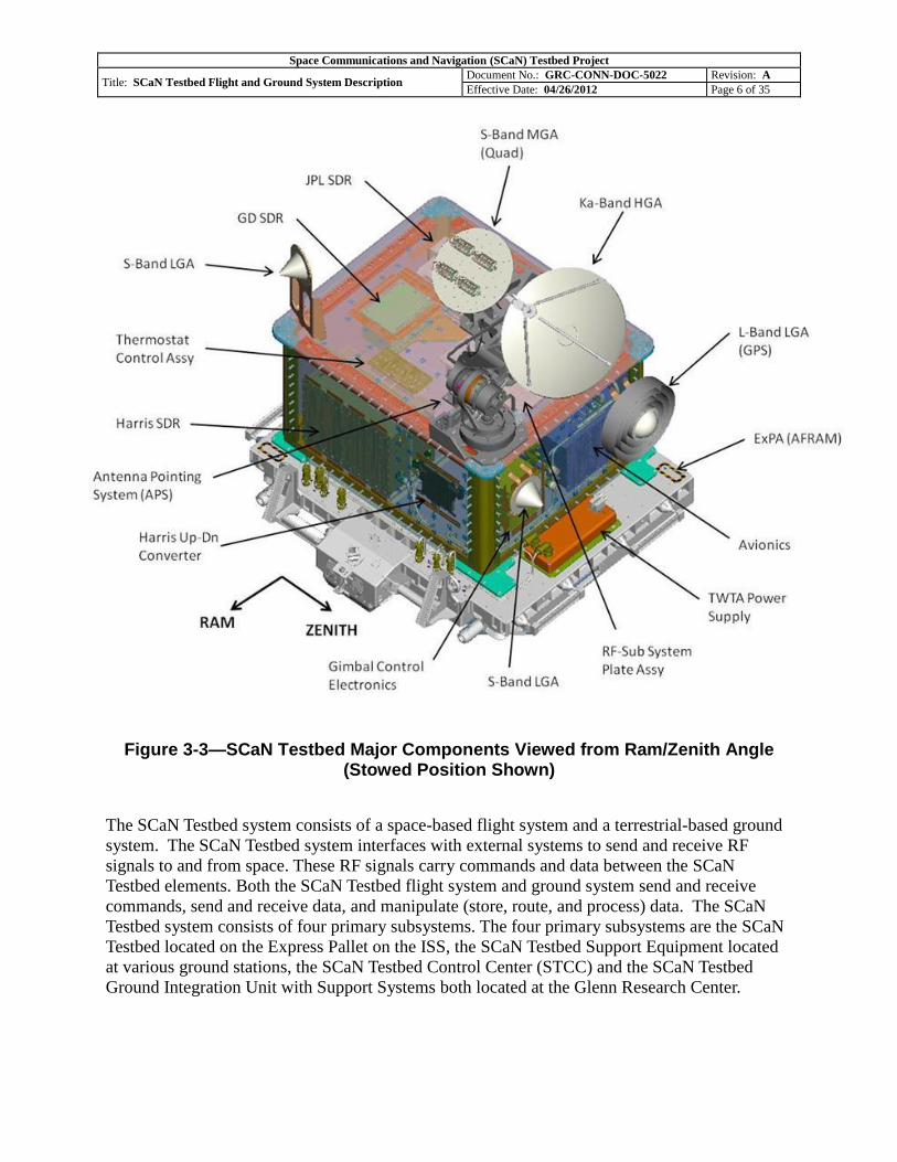
Figure 3-3—SCaN Testbed Major Components Viewed from Ram/Zenith Angle (Stowed
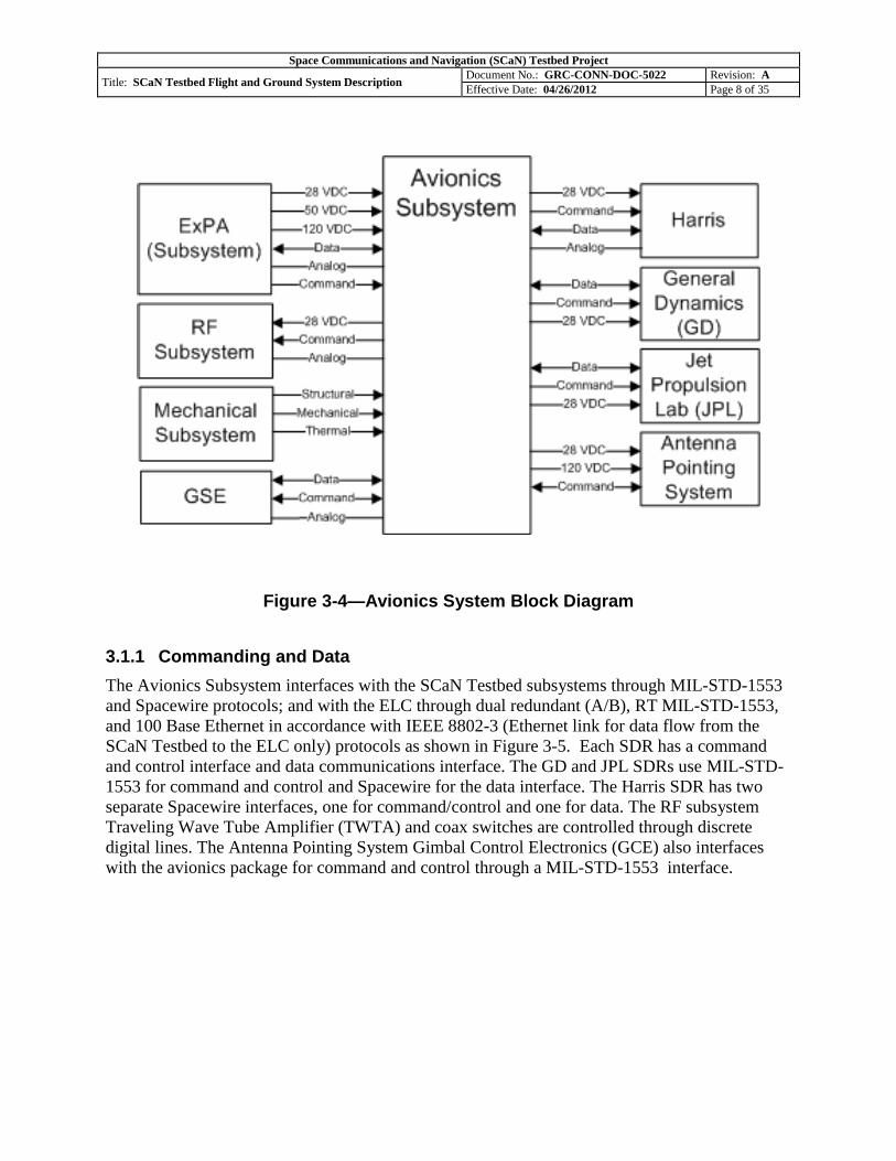
Position Shown) ...................................................................................................................... 6 Figure 3-4—Avionics System Block Diagram ............................................................................... 8 Figure 3-5—Flight System Block Diagram .................................................................................... 9 Figure 3-6—S-band RF Path Definition - CTS Matrix Switch Positions ..................................... 11
Figure 4-2—SCaN WSC-SDR and Control PC at GRC .............................................................. 28 Figure 4-3—SCaN Testbed Control Center Functional Diagram................................................. 30 Figure 4-4—Experimenter Access Points ..................................................................................... 31
Space Communications and Navigation (SCaN) Testbed Project
Title: SCaN Testbed Flight and Ground System Description Document No.: GRC-CONN-DOC-5022 Revision: A
Effective Date: 04/26/2012 Page 22 of 35
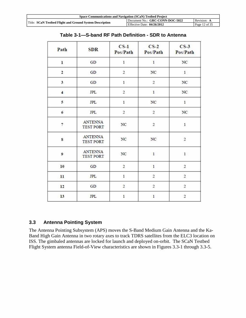
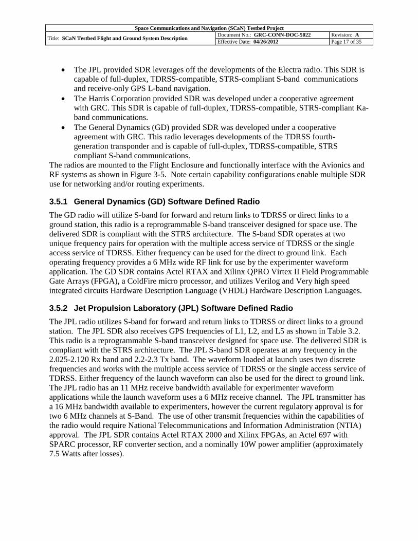
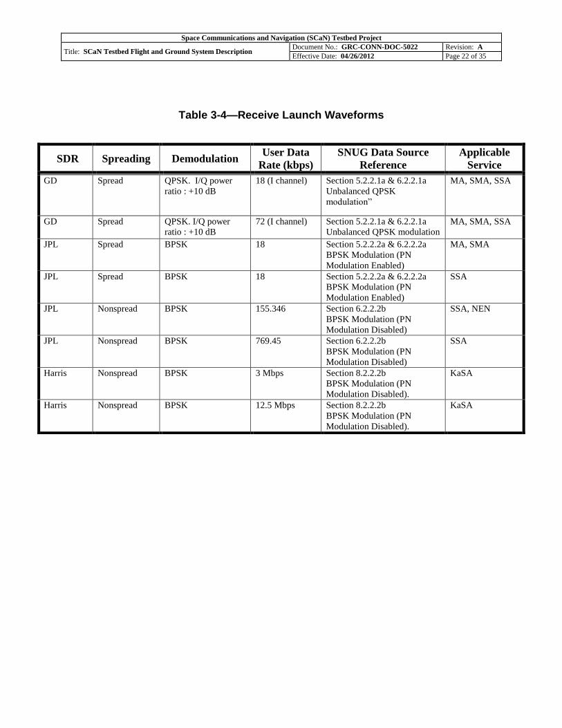
Table 3-4—Receive Launch Waveforms
SDR Spreading Demodulation User Data
Rate (kbps)
SNUG Data Source
Reference
Applicable
Service
GD Spread QPSK. I/Q power
ratio : +10 dB
18 (I channel) Section 5.2.2.1a & 6.2.2.1a
Unbalanced QPSK
modulation”
MA, SMA, SSA
GD Spread QPSK. I/Q power
ratio : +10 dB
72 (I channel) Section 5.2.2.1a & 6.2.2.1a
Unbalanced QPSK modulation
MA, SMA, SSA
JPL Spread BPSK 18 Section 5.2.2.2a & 6.2.2.2a
BPSK Modulation (PN
Modulation Enabled)
MA, SMA
JPL Spread BPSK 18 Section 5.2.2.2a & 6.2.2.2a
BPSK Modulation (PN
Modulation Enabled)
SSA
JPL Nonspread BPSK 155.346 Section 6.2.2.2b
BPSK Modulation (PN
Modulation Disabled)
SSA, NEN
JPL Nonspread BPSK 769.45 Section 6.2.2.2b
BPSK Modulation (PN
Modulation Disabled)
SSA
Harris Nonspread BPSK 3 Mbps Section 8.2.2.2b
BPSK Modulation (PN
Modulation Disabled).
KaSA
Harris Nonspread BPSK 12.5 Mbps Section 8.2.2.2b
BPSK Modulation (PN
Modulation Disabled).
KaSA
Space Communications and Navigation (SCaN) Testbed Project
Title: SCaN Testbed Flight and Ground System Description Document No.: GRC-CONN-DOC-5022 Revision: A
Effective Date: 04/26/2012 Page 23 of 35
3.7 Experimenter Data
Telemetry information generated by the SDRs, flight avionics, and the antenna/gimbal are
gathered by the PAS and sent to the STCC through the primary link. This data is displayed on
TReK workstations both in the STEC and STCC. A partial set of the telemetry items can be
displayed on the TReK workstation, in predesigned displays for each subsystem. Another option
for viewing telemetry is the Ad Hoc displays with which the experimenters can customize the
telemetry they view, for each subsystem. Log files can be created from the Ad Hoc screens and
are saved to the TReK workstation. Mission Operations personnel will not be normally logging
telemetry using the Ad Hoc displays in the STCC. Experimenters can log telemetry of interest
using Ad Hoc displays on the STEC TReK workstation.
Raw experiment data is the unprocessed return-link experiment data received by the STCC over
the experiment link after the NISN network overhead has been removed. Essentially this data is
the same as the demodulated and decoded return-link experiment data at White Sands.
For data returned over the SN, the raw experiment data is stored temporarily in the WSC SFEP
while being transmitted real-time to the experiment hardware for processing. After the pass, the
copy of the raw data is transferred from the WSC SFEP directly to the STCC SFEP storage
server. The data is then deleted from the WSC SFEP due to its limited storage capacity. Data
processed using launch waveforms and downlinked over the NEN, is not received real-time but
captured by WGS and then retrieved by Mission Operations from the WGS server, within that
shift. The stored raw experiment data, transmitted over either network, can be used to rerun
experiments in a playback configuration. The data is stored on the SFEP storage server for 6
months.
PI’s will be responsible for timely dissemination of experiment results and data publication. PIs
will be expected to support NASA organized workshops and conferences such as SCaN Testbed
Experimenters Conferences and ISS Utilization Conferences and present their findings.
Space Communications and Navigation (SCaN) Testbed Project
Title: SCaN Testbed Flight and Ground System Description Document No.: GRC-CONN-DOC-5022 Revision: A
Effective Date: 04/26/2012 Page 24 of 35
4.0 MISSION OPERATIONS NETWORK OVERVIEW
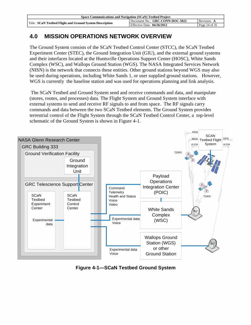
The Ground System consists of the SCaN Testbed Control Center (STCC), the SCaN Testbed
Experiment Center (STEC), the Ground Integration Unit (GIU), and the external ground systems
and their interfaces located at the Huntsville Operations Support Center (HOSC), White Sands
Complex (WSC), and Wallops Ground Station (WGS). The NASA Integrated Services Network
(NISN) is the network that connects these entities. Other ground stations beyond WGS may also
be used during operations, including White Sands 1, or user supplied ground stations. However,
WGS is currently the baseline station and was used for operations planning and link analysis.
The SCaN Testbed and Ground System send and receive commands and data, and manipulate
(stores, routes, and processes) data. The Flight System and Ground System interface with
external systems to send and receive RF signals to and from space. The RF signals carry
commands and data between the two SCaN Testbed elements. The Ground System provides
terrestrial control of the Flight System through the SCaN Testbed Control Center, a top-level
schematic of the Ground System is shown in Figure 4-1.
Figure 4-1—SCaN Testbed Ground System
Payload
Operations
Integration Center
(POIC)
White Sands
Complex
(WSC)
Wallops Ground
Station (WGS)
or other
Ground Station
NASA Glenn Research Center
GRC Building 333
Ground Verification Facility
GRC Telescience Support Center
CoNNeCT
Control
Center
CoNNeCT
Experiment
Center
Command
Telemetry
Health and Status
Voice
Video
Experimental data
Voice
Experimental data
Voice
SCAN
Testbed Flight
System
GPS
nLGAzLGA
MGA
HGA
Ground
Integration
Unit
Experimental
data
TDRS
TDRSSCaN Testbed Experiment Center
SCaN Testbed Control Center
Space Communications and Navigation (SCaN) Testbed Project
Title: SCaN Testbed Flight and Ground System Description Document No.: GRC-CONN-DOC-5022 Revision: A
Effective Date: 04/26/2012 Page 25 of 35
4.1 Primary Communication Path Elements
There are two communication paths for the SCaN Testbed mission. The primary
communications path (commanding and telemetry) will exist through the ISS S-band and Ku-
band links. This link will be coordinated through the Marshall Space Flight Center (MSFC)
Huntsville Operations Science Center (HOSC). The HOSC will receive the data from the SN and
forward it to the Glenn Research Center (GRC) SCaN Testbed Control Center (STCC) through
existing architecture.
The SCaN Testbed uses both the primary and experimental paths for commanding. Nominal
commanding will use the primary path. Commands will originate from the GRC TSC except for
13 critical commands. The critical commands will be sent by the Payload Rack Officer (PRO)
from the HOSC. The critical commands will reside only in the Payload Operations Integration
Center (POIC) database. In the future the SCaN Testbed will have the capability to use its RF
links to send non-critical commands through the SDRs to the Avionics. The TSC also contains
the Telescience Resource Kit (TReK) - a suite of PC-based software applications to monitor and
control payloads on-board the ISS. The TReK hosts a SCaN Testbed-specific Telemetry and
Acquisition Display System (CTADS) to display telemetry data from the SCaN Testbed and
configure commands for transmission. The primary path will be the baseline path for sending
new software to the SCaN Testbed and receiving telemetry and flight system stored data.
4.1.1 Huntsville Operations Support Center (HOSC)/Payload Operations Integration Center (POIC)
The Payload Operations Integration Center (POIC), located within MSFC's Huntsville
Operations Support Center (HOSC), houses the ground systems for managing the execution of
on-orbit International Space Station (ISS) payload operations including telemetry, command,
voice, video, information management, data reduction, and payload planning systems. All POIC
ground systems are distributed to the STCC.
The POIC contains several data and network systems that provide various capabilities:
The Payload Data Services System (PDSS) is used to receive, process, store (for 2 years),
and distribute International Space Station (ISS) 150 Mbps Payload telemetry data to the
POIC, International Partners, Telescience Support Centers and other remote user
facilities.
The Enhanced Huntsville Operations Support Center (EHOSC) performs command processing
and real-time and near real-time telemetry processing for simulation, training, and flight
operations.
The Payload Planning System (PPS) provides a set of software tools to automate the
planning, scheduling, and integration on ISS payload operations during pre-increment
planning, weekly planning, and real-time operations execution.
Space Communications and Navigation (SCaN) Testbed Project
Title: SCaN Testbed Flight and Ground System Description Document No.: GRC-CONN-DOC-5022 Revision: A
Effective Date: 04/26/2012 Page 26 of 35
4.2 Experiment Communication Path Elements
The second communication path (commanding and bidirectional data) is the experimental link
with the SN and the NEN. This link will be scheduled directly by the STCC with the supporting
elements. This link includes S-band and Ka-band services to the Space Network and S-band to
the NEN. Users will coordinate their ground station use with the STCC.
Forward Link: GRC STCC through NISN to White Sands to TDRSS to SCaN Testbed.
Return Link: SCaN Testbed to TDRSS to White Sands through NASA Integrated
Services Network NISN to GRC STCC.
Uplink: GRC STCC through NISN to Ground Station (e.g. WFF) to SCaN Testbed.
Downlink: SCaN Testbed to Ground Station (e.g. WFF) through NISN to GRC STCC.
4.2.1 Tracking and Data Relay Satellite (TDRS)
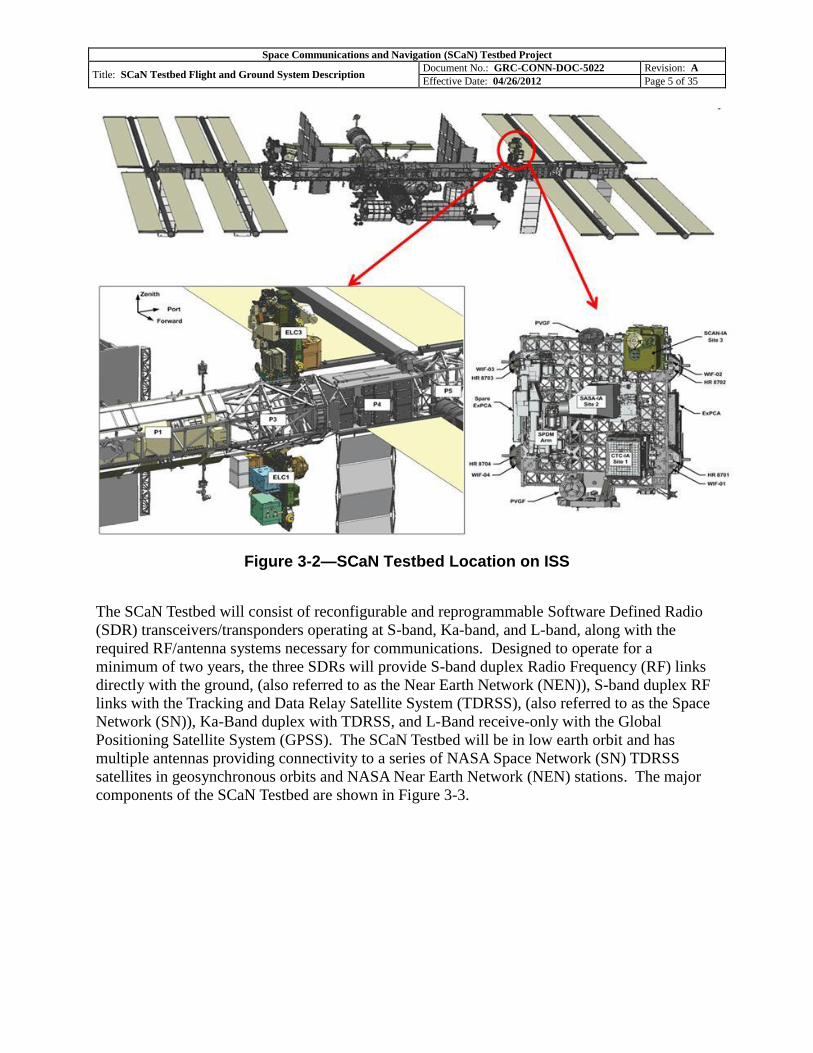
The SCaN Testbed located on the ISS will communicate with WSC ground stations via TDRS
satellites using Ka-band and S-band. The Tracking and Data Relay Satellite System (TDRSS) is
used by NASA and other United States government agencies for communications to and from
independent "User Platforms" such as the SCaN Testbed on the ISS. Full details of the TDRSS
are contained in the Space Network Users Guide (SNUG).
4.2.2 White Sands Complex (WSC)
The White Sands Complex (WSC) consists of two highly automated functionally identical
ground terminals. The White Sands Ground Terminal Upgrade also known as Cacique, and the
Second TDRSS Ground Terminal also known as Danzante, provide a relay interface between
the space segment, the ground segment and the other ground elements such as the HOSC.
The WSC, or TDRSS ground segment, includes the transmit and receive equipment to support
the four types of available customer satellite communications services: Multiple Access (S/MA),
Ku-Band Single Access (KuSA), Ka-Band Single Access (KaSA), and S-Band Single Access
(SSA). The SN can provide customer platform tracking and clock calibration services for S/MA,
SSA (including cross-support), and KuSA telecommunications services. The SN does not
provide tracking or clock calibration services for KaSA customers. TDRSS provides either two-
way range, two way doppler, or one-way doppler measurements. Sampled range and doppler
data are routed from the WSC to the GSFC Flight Dynamics Facility for orbit determination.
During initial launch and commissioning the three SDRs will be loaded with Space Network
User’s Guide (SNUG) compatible waveforms. Hardware checkout and validation will be carried
out with existing ground based receivers located at the White Sands Complex (WSC) TDRSS
terminal and WGS NEN ground stations. SCaN Testbed experiments that require unique
software and mission operations will have access to a SDR at the WSC separate from the legacy
services. A SDR capable of modulating and demodulating the experimental waveforms loaded
into the SCaN Testbed will be integrated into the White Sands Complex prior to the experiment
operations phase.
Space Communications and Navigation (SCaN) Testbed Project
Title: SCaN Testbed Flight and Ground System Description Document No.: GRC-CONN-DOC-5022 Revision: A
Effective Date: 04/26/2012 Page 27 of 35
4.2.2.1 Legacy Services
Several types of telecommunications services are simultaneously available to customers. The
type of telecommunications service selected is determined by the data rate required, duration of
service period, and customer platform telecommunications system design. The two primary
telecommunications services are termed Multiple Access (MA) and Single Access (SA). The SA
services are available at S-band, Ku-band, and Ka-band (F8-F10 only) frequencies. Legacy
services consist of the following and are further described in the SNUG. Note that the legacy Ku
band services are listed as a reference only. The SDRs do not have Ku band capabilities.
The SN can provide any of the following services:
A forward service, defined as the communication path that generally originates at the
customer control center and is routed through WSC to the TDRS to the customer
platform.
A return service, defined as the communication path that generally originates at the
customer platform and is routed through the TDRS to WSC back to the customer control
center and/or data acquisition location.
Both forward and return services simultaneously.
MA (also referred to as S-band Multiple Access (SMA) for TDRS F8-F10) forward and return
services operate at fixed S-band frequencies (nominally 2106.4 MHz forward and 2287.5 MHz
return) and polarization (Left Hand Circular). Forward service operations are time-shared among
TDRS customers where one customer is supported per TDRS at a time.
SA services available through each TDRS SA antenna are: S-band Single Access Forward, S-
band Single Access Return, Ku-band Single Access Forward, Ku-band Single Access Reverse,
Ka-band Single Access Forward (F8-F10 only), and Ka-band Single Access Reverse (F8-F10
only). Each TDRS SA antenna has one polarizer (either Left Hand Circular or Right Hand
Circular) for each frequency band (S, Ku, or Ka). The forward and return polarization for each
band must be the same in order to obtain simultaneous forward and return services through the
same SA antenna.
The SN can simultaneously support S-band and K-band (either Ku-band or Ka-band (F8-F10
only)) forward and/or return services through one SA antenna to the same ephemeris. TDRS F8-
F10 cannot simultaneously support Ku-band and Ka-band services through one SA antenna.
TDRSS S-band Single Access (SSA) services include forward and return telecommunications
services, and tracking services. SSA return service includes service through the SN receive
equipment and an automated IF service, where SN IF services are available to customers on a
case-by-case basis, IF service requires the customer to provide the receiver equipment and the
SN only provides the signal at the IF.
Space Communications and Navigation (SCaN) Testbed Project
Title: SCaN Testbed Flight and Ground System Description Document No.: GRC-CONN-DOC-5022 Revision: A
Effective Date: 04/26/2012 Page 28 of 35
TDRSS Ka-band Single Access (KaSA) services include forward and return telecommunications
services. KaSA Return service includes 225 MHz service through the SN receive equipment and
IF service for the KaSA 225 MHz and KaSA 650 MHz channels, where the 225 MHz IF is not
automated, but is being considered for automation and the 650 MHz service has been automated.
Additionally, SN IF services are available to customers on a case-by-case basis, IF service
requires the customer to provide the receiver equipment and the SN only provides the signal at
the IF. Tracking services are not provided via KaSA.
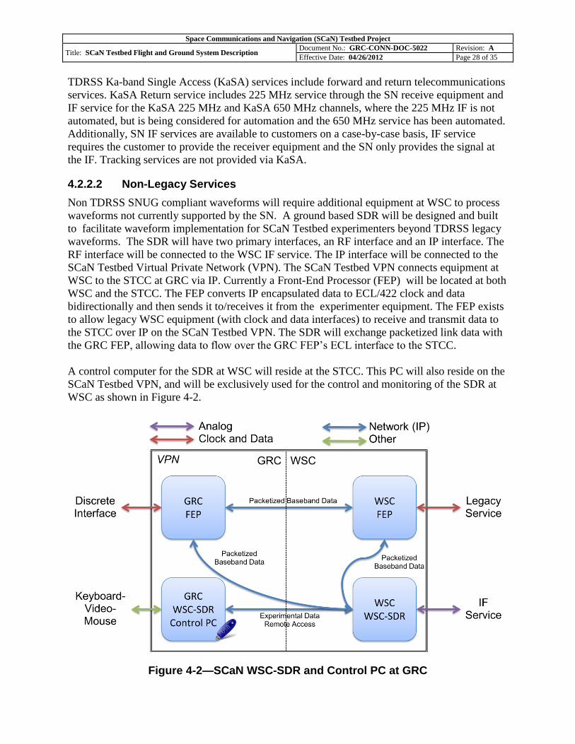
4.2.2.2 Non-Legacy Services
Non TDRSS SNUG compliant waveforms will require additional equipment at WSC to process
waveforms not currently supported by the SN. A ground based SDR will be designed and built
to facilitate waveform implementation for SCaN Testbed experimenters beyond TDRSS legacy
waveforms. The SDR will have two primary interfaces, an RF interface and an IP interface. The
RF interface will be connected to the WSC IF service. The IP interface will be connected to the
SCaN Testbed Virtual Private Network (VPN). The SCaN Testbed VPN connects equipment at
WSC to the STCC at GRC via IP. Currently a Front-End Processor (FEP) will be located at both
WSC and the STCC. The FEP converts IP encapsulated data to ECL/422 clock and data
bidirectionally and then sends it to/receives it from the experimenter equipment. The FEP exists
to allow legacy WSC equipment (with clock and data interfaces) to receive and transmit data to
the STCC over IP on the SCaN Testbed VPN. The SDR will exchange packetized link data with
the GRC FEP, allowing data to flow over the GRC FEP’s ECL interface to the STCC.
A control computer for the SDR at WSC will reside at the STCC. This PC will also reside on the
SCaN Testbed VPN, and will be exclusively used for the control and monitoring of the SDR at
WSC as shown in Figure 4-2.
Figure 4-2—SCaN WSC-SDR and Control PC at GRC
Space Communications and Navigation (SCaN) Testbed Project
Title: SCaN Testbed Flight and Ground System Description Document No.: GRC-CONN-DOC-5022 Revision: A
Effective Date: 04/26/2012 Page 29 of 35
4.2.3 Wallops Ground Station (WGS)/Other Near Earth Networks (NEN)
The SCaN Testbed can communicate directly with ground stations such as WGS or other ground
stations over S-band. Experimenter equipment connected to the ground stations will be used for
the ground experiment node. For experimenters using WGS, a NISN connection between the
STCC and WGS is available to route data to the STEC.
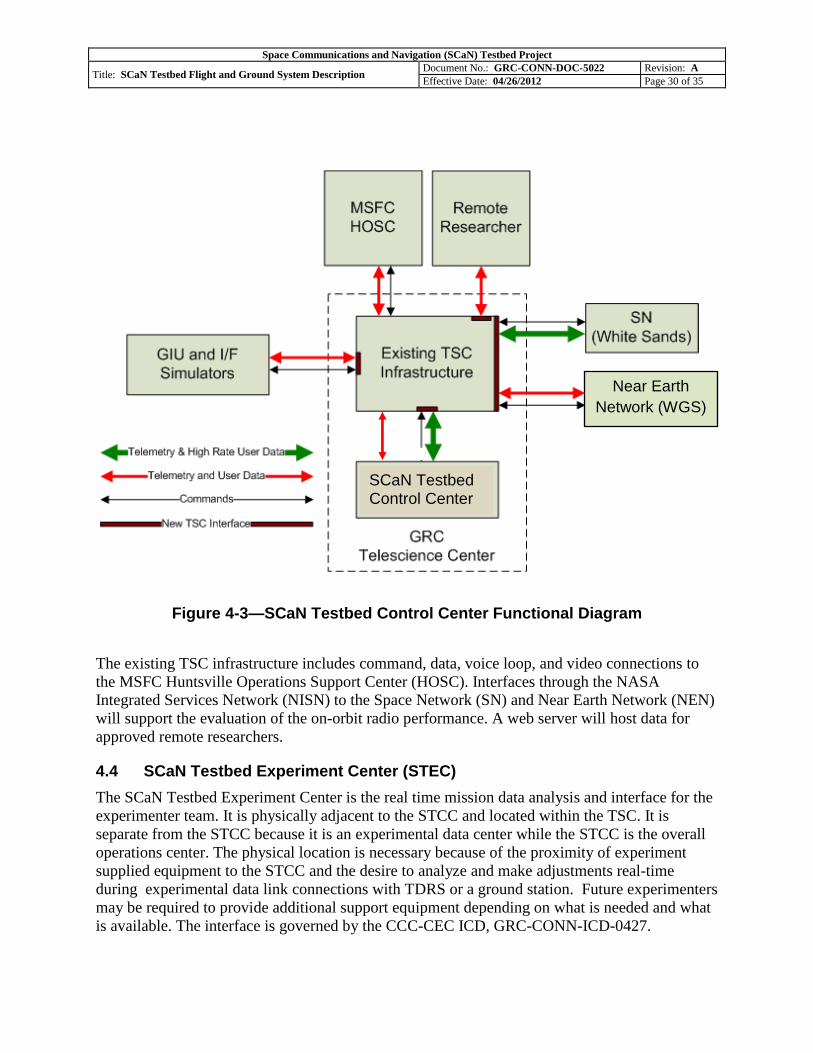
4.3 SCaN Testbed Control Center (STCC)
The STCC is the Mission Operations SCaN Testbed Control Center. It will reside within the
Telescience Support Center (TSC). The TSC facility located at GRC allows payload developers
and scientists on earth to monitor and control experiments onboard the International Space
Station (ISS). Data from the radios are received at WSC via TDRS and routed to GRC. The
STCC will make use of the existing TSC interfaces to the HOSC. The STCC will use the TSC
data network, which is an isolated network from the GRC campus network. Internet access to
external sites will also be available via a separate network, both for scheduling and other
interfaces such as the remote data access server.
The STCC will provide command and telemetry processing, experiment
demonstration/execution, experiment data archiving, and health and status data archiving. The
suite of data will be provided to approved users. The STCC will also interface with the Ground
Integration unit (GIU) for on-orbit anomaly resolution and waveform and Flight System software
verification prior to on-orbit upload. The GIU is a high fidelity duplicate of the flight SCaN
Testbed. The STCC diagram is shown in Figure 4-2.
Space Communications and Navigation (SCaN) Testbed Project
Title: SCaN Testbed Flight and Ground System Description Document No.: GRC-CONN-DOC-5022 Revision: A
Effective Date: 04/26/2012 Page 30 of 35
Figure 4-3—SCaN Testbed Control Center Functional Diagram
The existing TSC infrastructure includes command, data, voice loop, and video connections to
the MSFC Huntsville Operations Support Center (HOSC). Interfaces through the NASA
Integrated Services Network (NISN) to the Space Network (SN) and Near Earth Network (NEN)
will support the evaluation of the on-orbit radio performance. A web server will host data for
approved remote researchers.
4.4 SCaN Testbed Experiment Center (STEC)
The SCaN Testbed Experiment Center is the real time mission data analysis and interface for the
experimenter team. It is physically adjacent to the STCC and located within the TSC. It is
separate from the STCC because it is an experimental data center while the STCC is the overall
operations center. The physical location is necessary because of the proximity of experiment
supplied equipment to the STCC and the desire to analyze and make adjustments real-time
during experimental data link connections with TDRS or a ground station. Future experimenters
may be required to provide additional support equipment depending on what is needed and what
is available. The interface is governed by the CCC-CEC ICD, GRC-CONN-ICD-0427.
Near Earth
Network (WGS)
SCaN Testbed Control Center
Space Communications and Navigation (SCaN) Testbed Project
Title: SCaN Testbed Flight and Ground System Description Document No.: GRC-CONN-DOC-5022 Revision: A
Effective Date: 04/26/2012 Page 31 of 35
4.5 Ground Integration Unit (GIU) With Support Systems
The GIU with Support Systems (GIUSS) consists of the GIU, Antenna Pointing System (APS)
Rack, Test Equipment Interface (TEI) Racks #1 and #2, Power Acquisition System (PAS), two
S-Band TDRSS Simulators (TSIM), Ka-Band TSIM and Data Acquisition System and
Experiment Front End Processor (EFEP), ELC Suitcase Simulator (SCS), Telescience Resource
Kit (TReK) Workstation, WSC-SDR and GPS antenna. GSE is comprised of spectrum
analyzers, power meters, power supplies, personal computers, and other general test equipment.
The GIU includes SDR Engineering Models (EM) and an Avionics System (AS) spare Flight
Model (FM). The GIU also includes two Travelling Wave Tube Amplifiers (TWTA) EM,
Gimbal Control Electronics (GCE) EM, an Interconnect Harness EM, Temperature Sensors EM,
an Antenna Pointing System (APS) EM, Gimbals EM, an RF System EM/FM/SE custom
version, and additional Support Equipment (SE).
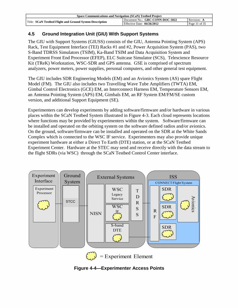
Experimenters can develop experiments by adding software/firmware and/or hardware in various
places within the SCaN Testbed System illustrated in Figure 4-3. Each cloud represents locations
where functions may be provided by experimenters within the system. Software/firmware can
be installed and operated on the orbiting system on the software defined radios and/or avionics.
On the ground, software/firmware can be installed and operated on the SDR at the White Sands
Complex which is connected to the WSC IF service. Experimenters may also provide unique
experiment hardware at either a Direct To Earth (DTE) station, or at the SCaN Testbed
Experiment Center. Hardware at the STEC may send and receive directly with the data stream to
the flight SDRs (via WSC) through the SCaN Testbed Control Center interface.
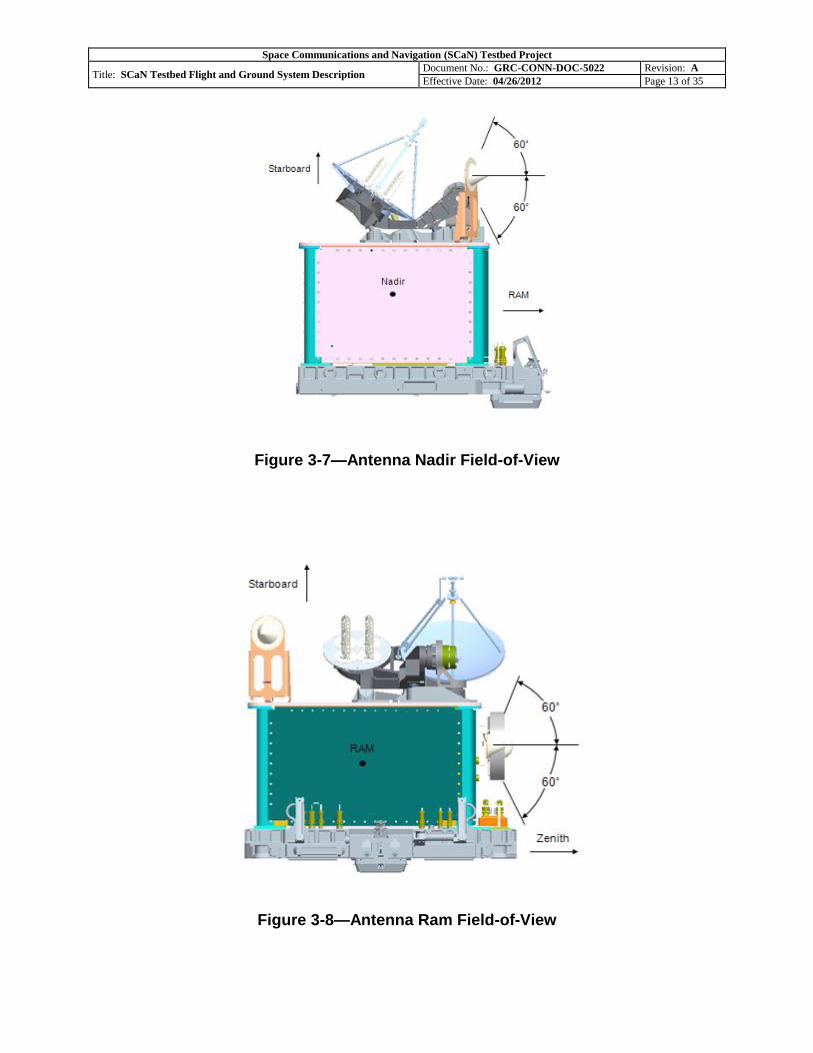
Figure 4-4—Experimenter Access Points
ISSCONNECT Flight System
Experiment
InterfaceExternal SystemsGround
System
SDR
Av
ion
ics
Experiment
Processor
CCC
NISN
WSCIF
WSCLegacy
Service
SDR
T
D
R
S
SR
F
S-band
DTESDR
= Experiment Element
STCC
Space Communications and Navigation (SCaN) Testbed Project
Title: SCaN Testbed Flight and Ground System Description Document No.: GRC-CONN-DOC-5022 Revision: A
Effective Date: 04/26/2012 Page 32 of 35
The Ground Integration Unit (GIU) will be utilized by experimenters for the following initial
experiment development activities.
Develop Avionics Software
Develop Ground Software
Develop an Operating Environment (OE) for a given radio
Develop Waveforms for the radios
Develop the On-Orbit Operating Procedures for Experiments
The GIU will support final experiment formal verification and validation consisting of the
following.
Avionics Software
Ground Software
Operating Environment (OE) for the radios
Waveforms for the radios
On-Orbit Operating Procedures for Experiments
The GIU will function as a tool to debug On-Orbit issues encountered on the Flight System.
Space Communications and Navigation (SCaN) Testbed Project
Title: SCaN Testbed Flight and Ground System Description Document No.: GRC-CONN-DOC-5022 Revision: A
Effective Date: 04/26/2012 Page 33 of 35
APPENDIX A ACRONYMS AND ABBREVIATIONS
A.1 Scope
This appendix lists the acronyms and abbreviations used in this document.
A.2 List of Acronyms and Abbreviations
Table A-1—Acronyms
Acronym Definition AFRAM Active - Flight Releasable Attachment Mechanism APS Antenna Pointing System AS Avionics System
BPSK Binary Phase-Shift Keying STCC SCaN Testbed Control Center STEC SCaN Testbed Experiment Center CM Configuration Management Comm Communication CONN CoNNeCT CoNNeCT Communications, Navigation, and Networking reConfigurable Testbed CPU Central Processing Unit
CTADS CoNNeCT Telemetry and Acquisition Display System
CTFS Common Time and Frequency System
CTS Coaxial Transfer Switch D/A Digital to Analog D/C Downconvert DSP Digital Signal Processing
DTE Direct To Earth DTN Delay Tolerant Networking EDS Experiment Development System EFEP Experiment Front End Processor
EHOSC Enhanced Huntsville Operations Support Center ELC Express Logistics Carrier EM Engineering Model EPMP Multi-Purpose Exposed Pallet EVA Extravehicular Activity EVR Extravehicular Robotics ExPA ExPRESS Pallet Adapter ExPRESS Expedite the Processing of Experiments to the Space Station Expt Experiment FEP Front End Processor
FM Frequency Modulation
FPGA Field-Programmable Gate Array FRAM Flight Releasable Attachment Mechanism GB Gigabyte GCE Gimbal Control Electronics GD General Dynamics GHz Gigahertz GIU Ground Integration Unit GIUSS Ground Integration Unit with Support Systems
GLPR NASA Glenn’s Configuration Management Procedural Requirement
Space Communications and Navigation (SCaN) Testbed Project
Title: SCaN Testbed Flight and Ground System Description Document No.: GRC-CONN-DOC-5022 Revision: A
Effective Date: 04/26/2012 Page 34 of 35
Gov Government
GPS Global Positioning System
GPU Ground Processor Unit
GRC Glenn Research Center
GSE Ground Support Equipment GSFC Goddard Space Flight Center HC Harris Corporation HOSC Huntsville Operations Support Center HTV H-II Transfer Vehicle I/O Input and Output ICD Interface Control Document IEEE Institute of Electrical and Electronic Engineers IF Intermediate Frequency IP Internet Protocol
IRIG-B Inter-Range Instrumentation Group - Time Code Format B
ISS International Space Station
ITS Integrated Truss Segment
JPL Jet Propulsion Laboratory
Ka-band 26.5 to 40 GHz KaSA Ka-band Single Access
KaSAR Ka-band Single Access Return
L-band 1 to 2 GHz LDPC Low Density Parity Check
LEO Low Earth Orbit LNA Low Noise Amplifier MA Multiple Access MHz Megahertz NASA National Aeronautics and Space Administration NEN Near Earth Network NISN NASA Integrated Services Network NTIA National Telecommunications and Information Administration OE Operating Environment Ops Operations PAS Power Acquisition System
PC Personal Computer
PDSS Payload Data Services System PI Principal Investigator
POIC Payload Operations Integration Center
PPS Pulses Per Second or Payload Planning System
PS Project Scientist
PSU Power Supply Unit QPSK Quadrature Phase-Shift Keying RF Radio Frequency RT Remote Terminal SA Single Access SAR Space Assurance and Requirements S-band 2 to 4 GHz SBIR Small Business Innovation Research SBU Sensitive But Unclassified SCaN Space Communications and Navigation SCS Suitcase Simulator
SDR Software Defined Radio
SDS Software Development System
SE Support Equipment
SEU Single Event Upset
Space Communications and Navigation (SCaN) Testbed Project
Title: SCaN Testbed Flight and Ground System Description Document No.: GRC-CONN-DOC-5022 Revision: A
Effective Date: 04/26/2012 Page 35 of 35
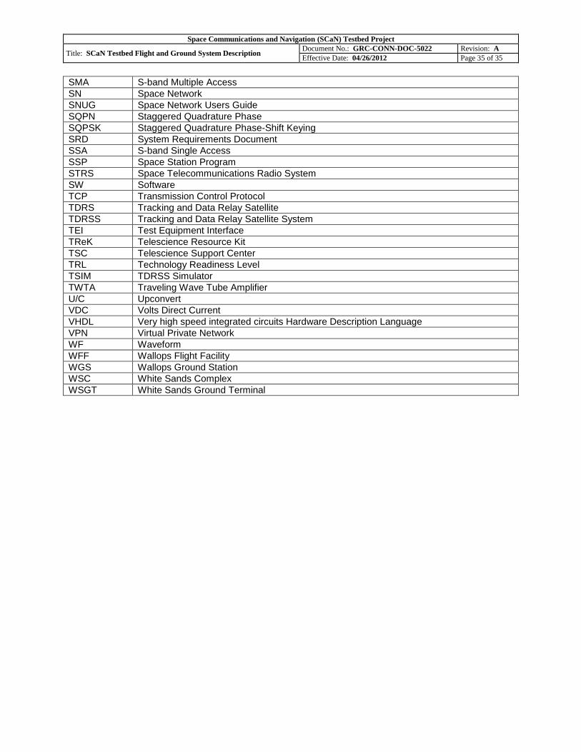
SMA S-band Multiple Access
SN Space Network
SNUG Space Network Users Guide
SQPN Staggered Quadrature Phase
SQPSK Staggered Quadrature Phase-Shift Keying SRD System Requirements Document SSA S-band Single Access
SSP Space Station Program
STRS Space Telecommunications Radio System
SW Software TCP Transmission Control Protocol
TDRS Tracking and Data Relay Satellite
TDRSS Tracking and Data Relay Satellite System
TEI Test Equipment Interface
TReK Telescience Resource Kit
TSC Telescience Support Center TRL Technology Readiness Level TSIM TDRSS Simulator TWTA Traveling Wave Tube Amplifier U/C Upconvert VDC Volts Direct Current VHDL Very high speed integrated circuits Hardware Description Language VPN Virtual Private Network
WF Waveform WFF Wallops Flight Facility WGS Wallops Ground Station
WSC White Sands Complex WSGT White Sands Ground Terminal


![McCormick - Aerodynamics, Aeronautics and Flight Mechanics [Partial Scan p1-179]](https://static.documents.pub/doc/80x56/547664afb4af9fbd568b45a6/mccormick-aerodynamics-aeronautics-and-flight-mechanics-partial-scan-p1-179-55845dba1f6f2.jpg)


