52 Oilfield Review High-Productivity Horizontal Gravel Packs Syed Ali Rick Dickerson Chevron Houston, Texas, USA Clive Bennett BP London, England Pat Bixenman Mehmet Parlar Colin Price-Smith Rosharon, Texas Steve Cooper BP Aberdeen, Scotland Jean Desroches Sugar Land, Texas Bill Foxenberg M-I Drilling Fluids Houston, Texas Keith Godwin Stone Energy Corporation Lafayette, Louisiana, USA Tim McPike Shell International E&P Rijswijk, The Netherlands Enzo Pitoni Giuseppe Ripa Eni Agip Milan, Italy Bill Steven Texaco Warri, Nigeria Dave Tiffin BP Houston, Texas Juan Troncoso Repsol-YPF Jakarta, Indonesia ClearPAC, MudSOLV, NODAL, QUANTUM and SandCADE are marks of Schlumberger. AllPAC and Alternate Path are marks of ExxonMobil; this technology is licensed exclu- sively to Schlumberger. To increase productivity and reduce cost and complexity, horizontal wells often are completed without casing across pay intervals. Stand-alone screens have been used in openholes, but increasingly, operators are gravel packing long intervals to stabilize boreholes, provide more reliable completions and mitigate sand-related problems such as erosion, surface handling and disposal. Loose formation grains and fine particles such as clays may be produced along with oil, gas and water from unconsolidated reservoirs. Installing completions to control sand without sacrificing productivity, flow control or recoverable reserves is challenging and expensive—as much as $3 million or more offshore. Costs of subsequent treatments to mitigate damage and future reme- dial interventions also are extremely high—up to $1 million per job in deepwater and subsea wells. Operators need reliable sand-control measures, implemented correctly the first time, especially for horizontal, openhole wells in high- permeability formations. Sand production, or sanding, is a function of rock strength, in-situ stresses, produced fluids and changes in flow rate related to pressure drop, or drawdown. High production rates, increasing effective stress due to depletion, and water breakthrough contribute to sanding. Problems associated with produced sand range from surface handling and disposal to erosion of subsurface or surface equipment and loss of well control. 1 If sand causes tubular or completion- equipment failures, production and reserve recovery can be delayed, or even lost, when costs to sidetrack or redrill a well are prohibitive. Operators use various techniques to minimize sand in produced fluids (next page). Sand-control methods include limiting well flow to rates below the onset of sanding, in-situ consolidation, selec- tive or oriented perforating, gravel packing and frac packing. 2 Frac packing combines short, wide hydraulic fractures, or tip-screenout designs, with gravel packing. To control sand in openhole completions, operators use stand-alone screens, gravel packs, frac packs, and recently, expand- able screens (see “Emerging Sand-Control Techniques,” page 72 ). Restricting production, although successful in the past, adversely impacts well profitability and is not practical in today’s economy, especially for high-cost, high-rate wells. In-situ consolidation locks sand grains in place by injecting resins and catalysts into formations, generally through per- forations in casing. Chemical placement and diversion across large zones and all perforations are difficult. Selective and oriented perforating attempt to prevent sand production by avoiding weakly consolidated intervals or aligning perfo- rations with maximum in-situ stresses to increase perforation stability. 3 An effective and widely used sand-control method, gravel packing places granular media, or gravel, around mechanical filters, or metal screens, inside perforated casing or openhole. 4 The “gravel” is clean, round natural sand or syn- thetic material that is small enough to exclude formation grains and some fine particles from produced fluids, but large enough to be held in place by screens. A gravel and carrier-fluid slurry is pumped into perforations and the annulus between screens and perforated casing or open- hole. Gravel is deposited as carrier fluid leaks into formations or circulates back to surface through the screens. For help in preparation of this article, thanks to Hal Riordan, Houston, Texas, USA; and Ray Tibbles, Rosharon, Texas.
Transcript
52 Oilfield Review
High-Productivity Horizontal Gravel Packs
Syed Ali Rick Dickerson Chevron Houston, Texas, USA
Clive Bennett BP London, England
Pat Bixenman Mehmet Parlar Colin Price-Smith Rosharon, Texas
Steve Cooper BP Aberdeen, Scotland
Jean Desroches Sugar Land, Texas
Bill Foxenberg M-I Drilling Fluids Houston, Texas
Keith Godwin Stone Energy Corporation Lafayette, Louisiana, USA
Tim McPike Shell International E&P Rijswijk, The Netherlands
Enzo Pitoni Giuseppe Ripa Eni AgipMilan, Italy
Bill Steven Texaco Warri, Nigeria
Dave Tiffin BP Houston, Texas
Juan Troncoso Repsol-YPF Jakarta, Indonesia
ClearPAC, MudSOLV, NODAL, QUANTUM and SandCADEare marks of Schlumberger. AllPAC and Alternate Path aremarks of ExxonMobil; this technology is licensed exclu-sively to Schlumberger.
To increase productivity and reduce cost and complexity, horizontal wells often
are completed without casing across pay intervals. Stand-alone screens have
been used in openholes, but increasingly, operators are gravel packing long
intervals to stabilize boreholes, provide more reliable completions and mitigate
sand-related problems such as erosion, surface handling and disposal.
Loose formation grains and fine particles such asclays may be produced along with oil, gas andwater from unconsolidated reservoirs. Installingcompletions to control sand without sacrificingproductivity, flow control or recoverable reservesis challenging and expensive—as much as $3 million or more offshore. Costs of subsequenttreatments to mitigate damage and future reme-dial interventions also are extremely high—up to $1 million per job in deepwater and subseawells. Operators need reliable sand-controlmeasures, implemented correctly the first time,especially for horizontal, openhole wells in high-permeability formations.
Sand production, or sanding, is a function ofrock strength, in-situ stresses, produced fluidsand changes in flow rate related to pressuredrop, or drawdown. High production rates,increasing effective stress due to depletion, andwater breakthrough contribute to sanding.Problems associated with produced sand rangefrom surface handling and disposal to erosion ofsubsurface or surface equipment and loss of wellcontrol.1 If sand causes tubular or completion-equipment failures, production and reserverecovery can be delayed, or even lost, when coststo sidetrack or redrill a well are prohibitive.
Operators use various techniques to minimizesand in produced fluids (next page). Sand-controlmethods include limiting well flow to rates belowthe onset of sanding, in-situ consolidation, selec-tive or oriented perforating, gravel packing andfrac packing.2 Frac packing combines short, wide
hydraulic fractures, or tip-screenout designs,with gravel packing. To control sand in openholecompletions, operators use stand-alone screens,gravel packs, frac packs, and recently, expand-able screens (see “Emerging Sand-ControlTechniques,” page 72).
Restricting production, although successful inthe past, adversely impacts well profitability andis not practical in today’s economy, especially forhigh-cost, high-rate wells. In-situ consolidationlocks sand grains in place by injecting resins andcatalysts into formations, generally through per-forations in casing. Chemical placement anddiversion across large zones and all perforationsare difficult. Selective and oriented perforatingattempt to prevent sand production by avoidingweakly consolidated intervals or aligning perfo-rations with maximum in-situ stresses toincrease perforation stability.3
An effective and widely used sand-controlmethod, gravel packing places granular media, orgravel, around mechanical filters, or metalscreens, inside perforated casing or openhole.4
The “gravel” is clean, round natural sand or syn-thetic material that is small enough to excludeformation grains and some fine particles fromproduced fluids, but large enough to be held inplace by screens. A gravel and carrier-fluid slurryis pumped into perforations and the annulusbetween screens and perforated casing or open-hole. Gravel is deposited as carrier fluid leaksinto formations or circulates back to surfacethrough the screens.
For help in preparation of this article, thanks to Hal Riordan,Houston, Texas, USA; and Ray Tibbles, Rosharon, Texas.
Summer 2001 53
In some areas and under certain formationconditions, stand-alone screens may be an alter-native to gravel packing or frac packing. Initialproductivity from screen-only completions is usu-ally good, but solids can eventually plug screens.In contrast, gravel packs tend to maintain pro-ductivity and sand-control integrity for longerperiods because of increased wellbore stability.However, many screen-only completions fail toadequately exclude sand. Other wells completedwithout gravel packing have not failed com-pletely, but produce at reduced rates because ofplugged or eroded stand-alone screens.
> Sand control. Selective or oriented perforating avoids weak zones and minimizes sand production; cemented casing provides positive zonal isolation.Cased-hole gravel packing provides sand control in laminated formations, lower quality sands or marginally economic vertical wells. Frac packingcombines stimulation and sand control in stacked pay or reservoirs with poorly sorted grains and low fluid transmissibility. In openhole, stand-alonescreens control sand in “clean” formations with large well-sorted grains and wells with short producing lives. Openhole gravel packs or frac packsmaintain productivity or injectivity longer than stand-alone screens in “dirty” formations with poorly sorted grains, high-rate wells with highertransmissibility and large reserves, and high-cost, high-risk deepwater or subsea completions.
1. Carlson J, Gurley D, King G, Price-Smith C and Walters F:“Sand Control: Why and How?” Oilfield Review 4, no. 4(October 1992): 41-53.
2. Hydraulic fracturing uses specialized fluids injected atpressures above the formation breakdown stress to cre-ate two fracture wings, or 180-degree opposed cracks,extending away from a wellbore. These fracture wingspropagate perpendicular to the least rock stress in apreferred fracture plane (PFP). Held open by a proppant,these conductive pathways increase effective wellradius, allowing linear flow into the fractures and to thewell. Common proppants are naturally occurring orresin-coated sand and high-strength bauxite or ceramicsynthetics, sized by screening according to standard USmesh sieves. In standard fracturing, the fracture tip is the final areathat is packed with proppant. A tip-screenout designcauses proppant to pack, or bridge, near the end of thefractures in early stages of a treatment. As additional
proppant-laden fluid is pumped, the fractures can nolonger propagate deeper into a formation and begin towiden or balloon. This technique creates a wider, moreconductive pathway as proppant is packed back towardthe wellbore.
3. Behrmann L, Brook JE, Farrant S, Fayard A,Venkitaraman A, Brown, A, Michel C, Noordermeer A,Smith P and Underdown D: “Perforating Practices ThatOptimize Productivity,” Oilfield Review 12, no. 1 (Spring2000): 52-74.
4. Sherlock-Willis TM, Morales RH and Price P: “A GlobalPerspective on Sand Control Treatments,” paper SPE50652, presented at the SPE European Petroleum Confer-ence, The Hague, The Netherlands, October 20-22, 1998.Parlar M and Albino EH: “Challenges, Accomplishments,and Recent Developments in Gravel Packing,” Journal ofPetroleum Technology 52, no. 1 (January 2000): 50-58.
As a result, there is a trend among operatorstoward gravel packing to protect screens andprovide better sandface completions. Sizinggravel correctly and completely packing theannulus stabilize formations and protect screensfrom erosion and gradual plugging. However,standard drilling and gravel-packing operationsmay trap mud and carrier-fluid residue betweengravel and formations or within the gravel pack,damaging both reservoir and pack permeabilities.Completion-induced damage results in high flow-initiation or drawdown pressures and reducedproductivity after gravel packing. This is espe-cially true when low-cost, conventional fluid sys-tems are used without regard for performance.
This article focuses on gravel packing of hori-zontal, openhole wells. We review sand-controlmeasures, including stand-alone screens, waterpacking and Alternate Path, or shunt-screen,technology. We discuss challenges and recentdevelopments in carrier fluids and filter-cakeremoval. Case histories demonstrate state-of-the-art wellbore cleanup, including chemicals,procedures and tools. Gravel-placement sim-ulation, techniques for gravel packing above frac-turing pressure or with oil-base fluids andexpandable screens also are included.
Casing or Openhole? Horizontal and high-angle drilling are common fornew and reentry wells even in reservoirs requiringsand-control completions. Cased-hole comple-tions are uncommon in horizontal wells becausecementing casing is difficult, perforating costs arehigher, and perforation cleanup to achieve effi-cient gravel packing often is problematic.Horizontal openholes also are less sensitive todrilling and completion damage because of sig-nificantly larger inflow areas. However, horizontalsections are drilled with specialized reservoirdrilling fluid (RDF) that contains primary polymersfor viscosity, bridging agents like sized calciumcarbonate [CaCO3] or sodium chloride [NaCl] saltand additives (usually starch or another polymer)tailored to control fluid loss (right).5
54 Oilfield Review
Loose filter cake, or "fluff"
Filter cake
300-ft/min [91-m/min] displacement rate
Borehole wall
Formation0.04 in.1 mm
> Filter cake. A properly formulated and conditioned reservoir drilling fluid (RDF) deposits a thin, low-permeability filter cake on borehole walls that does not deeply invade formations. Componentsinclude polymers for viscosity, bridging and weighting agents, and fluid-loss additives that seal withina few formation-grain diameters to minimize fluid and particulate invasion of productive intervals.Base brines, salts, CaCO3 and barite are common weighting agents. Bridging agents and fluid-lossadditives pack against a borehole wall. Proper RDF conditioning and wellbore displacements removeloose RDF material, or “fluff,” and minimize filter-cake thickness.
1000100
Mobility (Kh/µ), 1000 mD-ft/cp
Flow
effi
cien
cy, %
1011
10
100
Reduced flow efficiency
High flow efficiency
Best-fit curve for 12 high-rate wells Best-fit curve for 8 high-rate wells
Cased-Hole Frac-Pack Productivity
> Casing or openhole? Production data demonstrate the impact of perforated casing on wellinflow performance. In reservoirs with lower transmissibility—permeability times height (kh)divided by fluid viscosity (µ)—below about 40,000 mD-ft/cp, flow efficiency is high for perforated,cased-hole completions with frac-packs for sand control and stimulation. In high-rate wells,however, stimulation benefits can be lost when reservoir kh is high or fluid viscosity is lowbecause flow is choked by perforations. In formations with kh/µ greater than 40,000 mD-ft/cp,operators should consider openhole completions and, if possible, horizontal sections in payintervals to avoid reduced flow efficiency from perforation restrictions and turbulence. Stand-alone screens, openhole gravel packs and screens that expand against borehole walls are sand-control options for high-transmissibility reservoirs.
Summer 2001 55
Exposing more of the reservoir to a wellboreincreases productivity and injectivity whilereducing pressure drop and decreasing flowvelocities in formations. Less drawdown andlower fluid velocities also minimize sand produc-tion in some formations. Because cased-holeperforations and flow turbulence limit productiv-ity, particularly in high-rate wells, operators oftencomplete horizontal wells openhole for optimalproductivity.6 Using reservoir transmissibility—permeability times height (kh) divided by fluid vis-cosity (µ)—as a basis, BP evaluated frac-packed,cased-hole well productivity in terms of flow effi-ciency (previous page, top).7
As reservoir-fluid viscosity increases or per-meability and net-to-gross pay decrease—lessproductive pay, more silts and shales—operatorsmay need to frac-pack wells for stimulation and sand control in laminated or layered reser-voirs. As reservoir-fluid viscosity decreases orformation permeability and net-to-gross payincrease—more productive pay, fewer silts andshales—perforated casing reduces productionefficiency and stimulation benefits may benegated because flow is choked by perforations.
In high-permeability, high-productivity forma-tions, operators should consider openhole comple-tions with high-angle or horizontal sections inreservoirs, and stand-alone screens, gravel packsor expandable screens for sand control. Openholecompletions requiring sand control almost doubledfrom 1997 to 2000. Of these wells, about 20% were gravel packed in 1997 and 1998 com-pared with 40% in 2000. This trend is projected tocontinue, reaching about 60% in 2003.8 Controllingsand production in long, horizontal openholesrequires new technologies, detailed engineering,advanced planning and care execution.
Stand-Alone Screens or Gravel Packing? In the 1980s and early 1990s, stand-alone screenswere the primary sand-control option for horizon-tal openholes. Gravel packing long sections wasnot considered feasible. Operators installed con-ventional wire-wrap screens in openholes with-out gravel packing, but eventually turned toprepacked and premium-mesh designs for betterperformance and reliability (above right).
Because of larger inflow areas, initial produc-tivity from horizontal screen-only completions isusually higher and flow rates per unit length ofwellbore are lower than in vertical wells.However, many screen-only completions loseproductivity as formation solids plug screens,eventually failing because of increased sand pro-duction from high-velocity erosion of remaining
open screen areas. At first, stand-alone screenswere run in unconditioned drilling mud instead ofclean, filtered completion fluid. Poor mud filteringand conditioning, inadequate wellbore displace-ments after drilling and before installing screens
and lack of filter-cake cleanup led to screen plugging and low productivity.
Installing screens in openhole without gravel packing is successful in many wells, but effectiveness and reliability vary.9
5. Houwen O, Ladva H, Meeten G, Reid P and Williamson D:“A New Slogan for Drilling Fluids Engineers,” OilfieldReview 9, no. 1 (Spring 1997): 2-16.
6. Tiffin D, Stevens B, Park E, Elliott F and Gilchrist J:“Evaluation of Filter Cake Flowback in Sand ControlCompletions,” paper SPE 68933, presented at the SPEEuropean Formation Damage Conference, The Hague,The Netherlands, May 21-22, 2001.
7. Bennett CL: “Sand Control Design for Open Hole Comple-tions,” SPE Distinguished Lecturer Program presenta-tions, September 1999 to May 2000.
Wire-Wrap Screen Prepacked Screen
Premium-Mesh Screen
Perforated basepipe
Wire wrap
Protectivecover
High- permeability
gravel
Porous-membrane,fiber or metal-sintered
laminate
> Sand-control screens (Courtesy of U.S. Filter/Johnson Screens). Wire-wrapscreens, the most common design, generally consist of a drilled or slottedbasepipe with wire filters spaced to retain specific gravel sizes. In early versions, fluids flowed only through openings in the basepipe, so ribs, or rods,were added to form a small annulus for increased flow capacity and to reduceplugging. Prepacked screens are manufactured with high-permeability resin-coated gravel between two layers of wire-wrap filter media. Premium-meshscreen designs use a specialized wire-cloth media around a wire-wrap-screen.These screens usually include a shroud with drilled holes for additional pro-tection during installation or have openings designed to reduce erosion causedby sand grains and fine particles impacting directly on the internal filter mediaat high velocity.
8. Parlar M, Bennett, Gilchrist J, Elliott F, Troncoso J, Price-Smith C, Brady M, Tibbles RJ, Kelkar S, Hoxha Band Foxenberg WE: “Emerging Techniques in GravelPacking Open-Hole Horizontal Completions in High-Performance Wells,” paper SPE 64412, presented at theSPE Asia Pacific Oil and Gas Conference and Exhibition,Brisbane, Queensland, Australia, October 16-18, 2000.
9. Richard BM, Montagna JM and Penberthy WL Jr :“Horizontal Completions—2 Stand-Alone Screens Vary inEffectiveness,” Oil & Gas Journal 95, no. 32 (August 11,1997): 63-69.
Initially, failure rates averaged 50 to 65% for screen-only completions, but decreased toabout 20% as drilling fluids and cleanup techniques improved.10 Wells with reactive siltsand shales still have high failure rates caused bysand production and reduced productivity due toplugging of stand-alone screens. In the NorthSea, recovery factors for screen-only wells gener-ally meet expectations; sand-control failures havebeen low, but have increased over time. Some
stand-alone screen completions, however, pro-duce at restricted rates because of sand produc-tion, screen plugging and erosion, and are not yetclassified as failures.
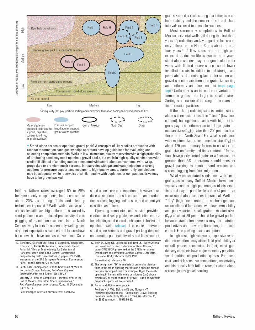
Operating companies and service providerscontinue to develop guidelines and define criteriafor selecting sand-control techniques in horizontalopenhole wells (above). The choice betweenstand-alone screens and gravel packing dependson formation permeability, clay and fines content,
grain sizes and particle sorting in addition to bore-hole stability and the number of silt and shaleintervals exposed to openhole sections.
Most screen-only completions in Gulf ofMexico horizontal wells fail during the first threeyears of production, and average time for screen-only failures in the North Sea is about three tofour years.11 If flow rates are not high andexpected productive life is two to three years,stand-alone screens may be a good solution forwells with limited reserves because of lowerinstallation costs. In addition to rock strength andpermeability, determining factors for screen andgravel selection are formation grain-size sortingand uniformity and fines content (next page,top).12 Uniformity is an indication of variation information grains from larger to smaller sizes.Sorting is a measure of the range from coarse tofine formation particles.
If the risk of producing sand is limited, stand-alone screens can be used in “clean” (low finescontent), homogeneous sands with high net-to-gross pay and uniformly sorted, large grains—median sizes (D50) greater than 200 µm—such asthose in the North Sea.13 For weak sandstoneswith medium-size grains—median size (D50) ofabout 125 µm—primary factors to consider aregrain size uniformity and fines content. If forma-tions have poorly sorted grains or a fines contentgreater than 5%, operators should considergravel packing to combat sand erosion andscreen plugging from fines migration.
Weakly consolidated sandstones with smallgrains, as in many Gulf of Mexico formations,typically contain high percentages of dispersedfines and clays—particles less than 44 µm—thatmake stand-alone screens impractical. Wells in“dirty” (high fines content) or nonhomogeneousunconsolidated formations with low permeabilityand poorly sorted, small grains—median sizes(D50) of about 80 µm—should be gravel packedbecause stand-alone screens may not maintainproductivity and provide reliable long-term sandcontrol. Frac packing also is an option.
In high-cost, high-rate wells, expensive reme-dial interventions may affect field profitability oroverall project economics. In fact, most gas-delivery contracts have major monetary penaltiesfor defaulting on production quotas. For thesecost- and risk-sensitive completions, uncertaintyand historically high failure rates for stand-alonescreens justify gravel packing.
56 Oilfield Review
10. Bennett C, Gilchrist JM, Pitoni E, Burton RC, Hodge RM,Troncoso J, Ali SA, Dickerson R, Price-Smith C andParlar M: “Design Methodology for Selection ofHorizontal Open-Hole Sand Control CompletionsSupported by Field Case Histories,” paper SPE 65140,presented at the SPE European Petroleum Conference,Paris, France, October 24-25, 2000.
11. Perdue JM: “Completion Experts Study Gulf of MexicoHorizontal Screen Failures, Petroleum EngineerInternational 69, no. 6 (June 1996): 31-32.McLarty J: “How to Complete a Horizontal Well in theGulf of Mexico: Operators Share Experiences,”Petroleum Engineer International 70, no. 11 (November1997): 63-70. Schlumberger internal horizontal-well database.
Medium
Sand quality (net pay, particle sorting and uniformity, formation homogeneity and permeability)
Med
ium
Like
lihoo
d of
sol
ids
prod
uctio
n (ro
ck s
treng
th a
nd in
-situ
stre
sses
)
Low
High
Low High
Field I Field HField F
Major depletion expected (poor aquifer support, depletion, compaction drive, or gas blowdown)
Gulf of Mexico North Sea OtherPressure support (good aquifer support,gas or water injection)
Openhole gravel pack
No sand control
Openhole gravel pack or expandable screens
Field AField B
Premium-mesh stand-alone screens
Conventional stand-alone screens
Field G
Field F1 Field E
Field D
Field C
> Stand-alone screen or openhole gravel pack? A crossplot of likely solids production withrespect to formation sand quality helps operators develop guidelines for evaluating andselecting completion methods. Wells in low- to medium-quality reservoirs with a high probabilityof producing sand may need openhole gravel packs, but wells in high-quality sandstones withsimilar likelihood of sanding can be completed with stand-alone conventional wire-wrap,prepacked or premium-mesh screens. In reservoirs with gas and water injection or strongaquifers for pressure support and medium- to high-quality sands, screen-only completionsmay be adequate, while reservoirs of similar quality with depletion, or compaction, drive mayhave to be gravel packed.
12. Tiffin DL, King GE, Larese RE and Britt LK: “New Criteriafor Gravel and Screen Selection for Sand Control,”paper SPE 39437, presented at the SPE InternationalSymposium on Formation Damage Control, Lafayette,Louisiana, USA, February 18-19, 1998. Bennett et al, reference 10.
13. The designation “D” in analysis of grain-size distribu-tions is the mesh opening that retains a specific cumula-tive percent of particles. For example, D50 is the meshopening, in inches millimeters or microns (µm) abovewhich 50% of the formation or gravel—sand or syntheticproppant—particles are retained.
14. Parlar and Albino, reference 4. Penberthy Jr WL, Bickham KL and Nguyen HT:“Horizontal Completions—Conclusion: Gravel PackingPrevents Productivity Decline,” Oil & Gas Journal 95,no. 35 (September 1, 1997): 56-60.
Summer 2001 57
Unless formations have extremely clean,well-sorted grains, subsea production and injec-tion wells that may produce sand and mostdeepwater—greater than 1000 to 2000 ft [305 to 610 m]—completions should be gravel packed to avoid costly remedial interventions, espe-cially when large reserve volumes are involved.High-rate gas wells also need to be gravelpacked when sanding and screen erosion causesafety concerns.
Stand-alone screens may be justifiable incertain applications: • nonsubsea wells with a short productive life
and uniform hole collapse, regardless of rate • low-rate nonsubsea wells with few shale or
silt intervals and partial or no hole collapse • nonsubsea injection wells with a small wellbore-
screen annulus that limits flow around screens.Marginal economics, capital investment limi-
tations, potential completion damage or produc-tivity reduction and loss of zonal isolation arereasons not to gravel pack openhole horizontalwells. However, most operators agree that gravelpacking is preferred in horizontal openhole wellsto reduce sand-related failures and minimizeassociated productivity decline. High-pressure,high-temperature (HPHT) wells may be excep-tions because of fluid performance and compati-bility limitations. These HPHT sand-controlapplications present challenges for completionengineers and are currently under evaluation.
Water Packing or Alternate Path Screens? Openhole gravel packing has evolved as operatorsand service companies gain experience and a bet-ter understanding of completion damage andgravel placement in horizontal wells. If gravelpacking is required, operators must choosebetween two field-proven techniques currentlyavailable for completing long openhole sections—water packing and Alternate Path screens.
Water packing uses low gravel concentra-tions—0.5 to 2 pounds of proppant added (ppa) pergallon [0.06 to 0.2 g/cm3]—transported in low-vis-cosity carrier fluids, usually brine (left).14
Stand-Alone Screen and Gravel-Pack Criteria for Completion Design
Formation characteristicsCompletion
type
Wire-wrap or prepacked screens
Premium-mesh screens
Openhole gravel pack
Content of fines less than 44 µm
Less than 2%
Less than 5%
Greater than 5%
Uniformity coefficient D40/D90
Less than 3
Less than 5
Greater than 5
Sorting coefficientD10/D95
Less than 10
Less than 10
Greater than 10
> Screen and gravel-pack criteria. As formations become less uniform, completionselection needs to incorporate parameters other than median (D50) grain sizesfrom sieve analysis. Sorting coefficient D10/D95, uniformity coefficient D40/D90 andpercentage of 44-µm and finer particles address formation quality and influencescreen and gravel-pack designs. For example, in wells with sorting coefficientgreater than 10, uniformity coefficient greater than 5 and 44-micron fines contentgreater than 5%, an openhole gravel pack may be the most appropriate choice.
Blank pipe
1 2 3 4 5
678910
SlurryHeel Toe
CasingScreens
Filter cakeOpenhole
Screen Washpipe
Gravel duneWash pipe
Beta wave
Alpha wave
Typical Surface Treating-Pressure Response for Water Packing
Preflush stage
Slurry stage
Displacement stage
Alpha wave: slurry transport along the screens
Slurry at toe of well Beta wave: gravelpacking from toe to heel
Annularpackoff
Surfa
ce tr
eatin
g pr
essu
re, p
si
Treatment duration, min
>Water packing. Gravel packing with low-viscosity fluids, usually brine, relies on deposition ofgravel around screens on the low side of an annulus, while slurry with low gravel concentrationsmoves in turbulent flow along the top (top and bottom right). The borehole must be sealed with anRDF filter cake to minimize fluid leakoff. If circulation—fluid returns to surface—is maintained, gravel moves toward the far end, or toe, of horizontal sections in an “alpha” wave (1 to 5). If a slurrydehydrates and forward packing ceases in intervals with high fluid losses, gravel fills the annulusand forms a bridge. The result is an incomplete pack beyond that point. After bridging occurs orgravel reaches the toe, packing proceeds back toward the beginning, or heel, of a horizontal sectionin a “beta” wave (6 to 10). Surface treating pressures provide an indication of how water-packingtreatments are progressing (bottom left).
The low side of an annulus is packed first untilgravel reaches the far end, also called the toe, oruntil gravel packs off and forms a bridge becauseof high fluid leakoff. Gravitational forces domi-nate this “alpha” wave, so gravel settles likewind-blown sand dunes on a beach until reach-ing an equilibrium height. If fluid flow remainsabove critical velocity for particle transport,gravel will move down a horizontal sectiontoward the toe.
After the alpha wave stops, a second, or“beta,” wave packs the annulus topside backtoward the beginning of a horizontal section, alsocalled the heel, from the toe or a bridge. The betawave requires enough fluid velocity to maintainturbulent flow and move gravel along the top of awellbore annulus. This wave continues until spacebetween pack and formation becomes small rela-tive to gravel particle size. Low-permeability filtercake is required to prevent fluid loss into forma-tions, maintain equilibrium gravel height, avoidgravel bridging, which leads to incomplete pack-ing, and allow screens to be installed without dif-ferential sticking. Reduced annular flow as a resultof fluid loss from filter-cake erosion or exceeding
fracturing pressure increases downstream gravelheight and the possibility of premature bridgingand voids in packs.
Water packing relies heavily on filter-cakeintegrity and may not completely pack the annu-lus, which may introduce uncertainty about com-pletion success and consistency. For this reason,specialized and carefully designed RDF is used todrill openhole reservoir sections. An RDF shouldform thin, low-permeability filter cake that is brit-tle, but able to withstand erosion while gravel isbeing pumped. These characteristics make filtercake easier to remove or, at least, less damagingto formation permeability.15
If required, cleanup treatments must followwater packing to maintain filter-cake integritywhile placing gravel. In reservoirs with low net-to-gross pay, silt and shale intervals exposed tocompletion fluids can be eroded and transportedby high-velocity flow for long periods, potentiallyreducing final gravel-pack permeability. Usingprepacked or premium-mesh screens to controlsand in case of an incomplete pack compensatessomewhat for water-packing limitations, but amore reliable method was needed.
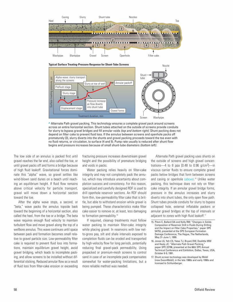
Alternate Path gravel packing uses shunts onthe outside of screens and high gravel concen-trations—4 to 8 ppa [0.48 to 0.96 g/cm3]—inviscous carrier fluids to ensure complete gravelpacks below bridges that form between screensand casing or openhole (above).16 Unlike waterpacking, this technique does not rely on filter-cake integrity. If an annular gravel bridge forms,pressure in the annulus increases and slurrydiverts into shunt tubes, the only open flow path.Shunt tubes provide conduits for slurry to bypasscollapsed hole, external inflatable packers orannular gravel bridges at the top of intervals oradjacent to zones with high fluid leakoff.17
58 Oilfield Review
15. Pitoni E, Ballard DA and Kelly RM: “Changes in SolidsComposition of Reservoir Drill in Fluids During Drillingand the Impact on Filter Cake Properties,” paper SPE54753, presented at the SPE European FormationDamage Conference, The Hague, The Netherlands, May 31-June 1, 1999.
16. Jones LG, Yeh CS, Yates TJ, Bryant DW, Doolittle MWand Healy JC: “Alternate Path Gravel Packing,” paper SPE 22796, presented at the 66th SPE AnnualTechnical Conference and Exhibition, Dallas, Texas, USA,October 6-9, 1991.
17. Shunt-screen technology was developed by Mobil (now ExxonMobil), in the late 1980s and early 1990s andlicensed to Schlumberger.
Typical Surface Treating-Pressure Response for Shunt-Tube Screens
Preflush stageAnnular packoffSlurry at toe of well
WashpipeScreen
> Alternate Path gravel packing. This technology ensures a complete gravel pack around screensacross an entire horizontal section. Shunt tubes attached on the outside of screens provide conduitsfor slurry to bypass gravel bridges and fill annular voids (top and bottom right). Shunt packing does notdepend on filter cake to prevent fluid loss. If the annulus between screens and openhole packs offprematurely (3), slurry diverts into the shunts and gravel packing proceeds toward the toe even withno fluid returns, or circulation, to surface (4 and 5). Pump rate usually is reduced after shunt flowbegins and pressure increases because of small shunt-tube diameters (bottom left).
Summer 2001 59
Large-scale tests simulating extremely highleakoff proved that single shunt tubes could pack2000-ft horizontal intervals even with no fluidreturns to surface.18 Engineers adapted AlternatePath screens for longer horizontal openholes bydesigning nozzles and shunts that reduce gravelbuildup inside shunts, by using nondamaging flu-ids with good gravel-carrying capacity and byinstalling pipe shrouds with drilled holes aroundthe entire assembly to help centralize screensand protect shunt tubes.
Gravel does not make turns into small exitports easily, so large angled nozzles extendinginto the flow stream reduce the tendency forgravel to settle and concentrate inside shunts.Shunts with ports, or nozzles, serve as packingtubes. For extremely long intervals, transportshunts without exit ports are attached along theentire length of screen assemblies to limit slurrydehydration by reducing carrier-fluid leakoff intothe annulus and deliver slurry to packing tubes at4 to 6 bbl/min [0.6 to 0.9 m3/min].
Transport tubes are connected to packingtubes by a manifold at each screen joint. Slurryflows down packing tubes or from transport topacking tubes and exits through wear-resistant,carbide nozzles to pack voids behind screens at0.5 to 2 bbl/min [0.08 to 0.3 m3/min]. Blank pipeabove a screen assembly also can be fitted withtransport tubes to provide a path for slurry incase of hole collapse or a gravel bridge at the topof an interval.
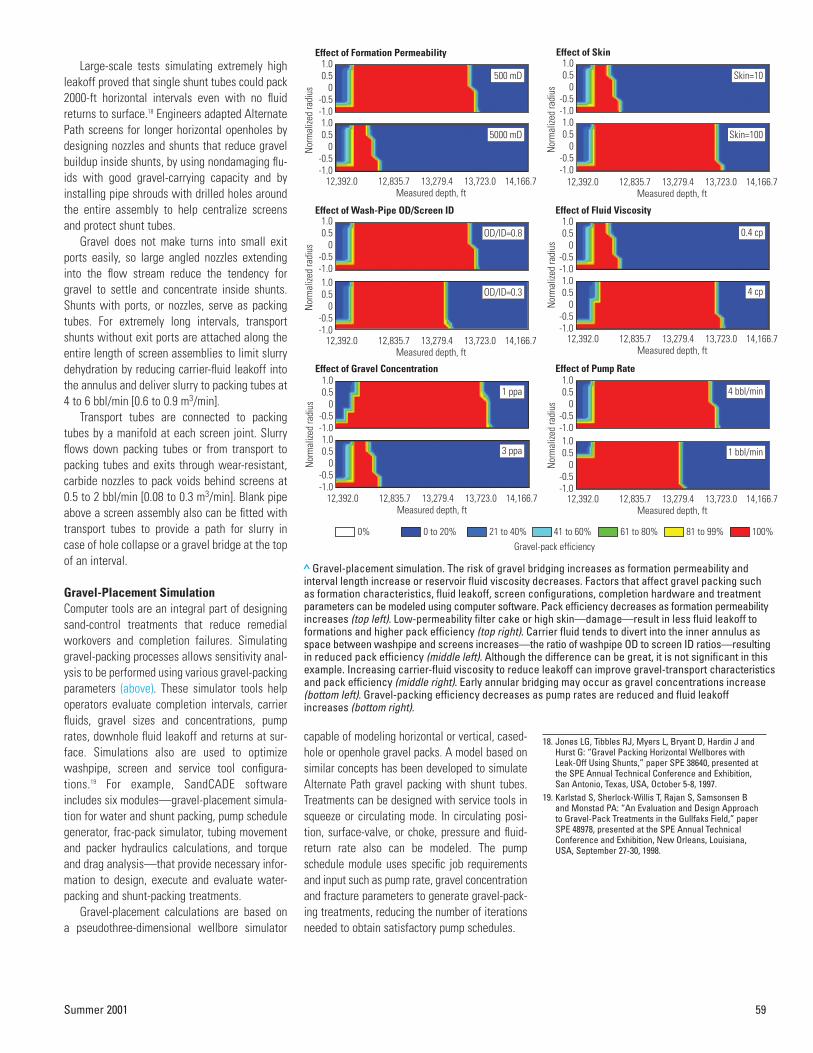
Gravel-Placement Simulation Computer tools are an integral part of designingsand-control treatments that reduce remedialworkovers and completion failures. Simulatinggravel-packing processes allows sensitivity anal-ysis to be performed using various gravel-packingparameters (above). These simulator tools helpoperators evaluate completion intervals, carrierfluids, gravel sizes and concentrations, pumprates, downhole fluid leakoff and returns at sur-face. Simulations also are used to optimizewashpipe, screen and service tool configura-tions.19 For example, SandCADE softwareincludes six modules—gravel-placement simula-tion for water and shunt packing, pump schedulegenerator, frac-pack simulator, tubing movementand packer hydraulics calculations, and torqueand drag analysis—that provide necessary infor-mation to design, execute and evaluate water-packing and shunt-packing treatments.
Gravel-placement calculations are based on a pseudothree-dimensional wellbore simulator
capable of modeling horizontal or vertical, cased-hole or openhole gravel packs. A model based onsimilar concepts has been developed to simulateAlternate Path gravel packing with shunt tubes.Treatments can be designed with service tools insqueeze or circulating mode. In circulating posi-tion, surface-valve, or choke, pressure and fluid-return rate also can be modeled. The pumpschedule module uses specific job requirementsand input such as pump rate, gravel concentrationand fracture parameters to generate gravel-pack-ing treatments, reducing the number of iterationsneeded to obtain satisfactory pump schedules.
18. Jones LG, Tibbles RJ, Myers L, Bryant D, Hardin J andHurst G: “Gravel Packing Horizontal Wellbores withLeak-Off Using Shunts,” paper SPE 38640, presented atthe SPE Annual Technical Conference and Exhibition,San Antonio, Texas, USA, October 5-8, 1997.
19. Karlstad S, Sherlock-Willis T, Rajan S, Samsonsen B and Monstad PA: “An Evaluation and Design Approachto Gravel-Pack Treatments in the Gullfaks Field,” paperSPE 48978, presented at the SPE Annual TechnicalConference and Exhibition, New Orleans, Louisiana,USA, September 27-30, 1998.
0% 0 to 20% 21 to 40% 41 to 60% 61 to 80% 81 to 99% 100%
> Gravel-placement simulation. The risk of gravel bridging increases as formation permeability andinterval length increase or reservoir fluid viscosity decreases. Factors that affect gravel packing such as formation characteristics, fluid leakoff, screen configurations, completion hardware and treatmentparameters can be modeled using computer software. Pack efficiency decreases as formation permeabilityincreases (top left). Low-permeability filter cake or high skin—damage—result in less fluid leakoff toformations and higher pack efficiency (top right). Carrier fluid tends to divert into the inner annulus asspace between washpipe and screens increases—the ratio of washpipe OD to screen ID ratios—resultingin reduced pack efficiency (middle left). Although the difference can be great, it is not significant in thisexample. Increasing carrier-fluid viscosity to reduce leakoff can improve gravel-transport characteristicsand pack efficiency (middle right). Early annular bridging may occur as gravel concentrations increase(bottom left). Gravel-packing efficiency decreases as pump rates are reduced and fluid leakoffincreases (bottom right).
In the past, frac packs, which often failedbecause of premature gravel packoff, weredesigned solely using hydraulic-fracturing simu-lators that neglected completion hardware insidewellbores—crossover ports in gravel-packingpackers, blank pipe, screens and washpipe.Users now can specify tip-screenout designs andsimulate frac-packing treatments with a recentlydeveloped coupled wellbore and fracture sim-ulator.20 This modified simulator, based on apseudothree-dimensional hydraulic fracturingsimulator, calculates parameters like gravel dis-tribution in fractures, fracture height and two-dimensional fluid flow as boundary conditions fora pseudothree-dimensional wellbore simulator.
Slurry flow is simulated along with well incli-nation effects, gravel settling and bridgingaround screens, and fluid flow through screens.In addition, the enhanced fracture simulator sup-ports tip-screenout designs in high-permeabilityformations. Inducing gravel packoff in wellboresby deliberately reducing pump rate or shiftingservice tools to circulation at the end of treat-ments also can be modeled.
Once a final pumping schedule is obtained, atubing-movement module calculates friction,buckling, ballooning, piston and thermal effects,and allows users to design seal assemblies inpackers that compensate for potential tubularmovement. Packer hydraulics calculations helpgenerate procedures to run gravel-pack packerssafely and avoid premature release. Torque anddrag analysis provides estimates to safely runcompletion assemblies to total depth withoutgetting stuck or damaging components.
Water Packing in China During May 2001, Schlumberger completed anoffshore oil well in China’s Bo Hai Bay where theoperator had drilled an 81⁄2-in. borehole for a pro-posed gravel pack. No fluid losses were reportedwhile drilling a 634-m [2080-ft] horizontal section.A series of SandCADE design simulations was runto optimize openhole water-packing procedures(below). Gravel-placement simulations indicatedthat 31⁄2-in. tubing would minimize gravel settlingand improve pumping efficiency.
Pumping rates from 3 to 8 bbl/min [0.5 to 1.25 m3/min] were modeled to determine packingefficiency. At both 7 and 8 bbl/min [1.1 and 1.25 m3/min] higher pressures and fluid leakoffresulted in gravel bridging and pack efficienciesof 58 and 88%, respectively. With no leakoff andfull returns to surface, pump rates of 3 to 6 bbl/min [0.95 m3/min] resulted in a 100% packefficiency, but 3 bbl/min was considered too lowbecause of potential gravel settling in low spotsalong a horizontal well profile.
Water packing at 5 bbl/min [0.8 m3/min] wasselected as the highest rate with lowest risk ofbridging that resulted in a complete pack. Thenext step was to determine allowable fluid lossby varying skin or formation permeability alongthe openhole from 5 mD and no losses to 350 mDand about 2 bbl/min [0.3 m3/min] of fluid returns.The alpha wave stalled when return rates fellbelow 2 bbl/min, and returns of less than 3 bbl/min were considered unacceptable by theoperator because of possible increasing lossesfrom filter-cake erosion.
Torque and drag monitoring and simulationwhile running and pulling drillpipe to displaceRDF with solids-free fluids helped the operatorestablish friction factors in casing and open-hole. These data were used in the SandCADEtorque and drag module to establish horizontallimits for various workstrings. This analysis pre-dicted possible buckling of 31⁄2-in. tubulars dur-ing screen installation.
In spite of additional precautions, bucklingproblems occurred as predicted while attemptingto run screens on 31⁄2-in. drillstring, so the screenassembly was pulled and rerun on 5-in. drillpipe.A water-packing procedure was performed afterswitching back to a 31⁄2-in. workstring. To verifycirculation, fluids returns of 4.7 bbl/min [0.75 m3/min] were established by pumpingfiltered brine at 5 bbl/min before placing gravelwith 0.5-ppa slurry. Pumping for 11 hours at 5 bbl/min resulted in an estimated pack effi-ciency of 158% based on 81⁄2-in. gauge holevolume. A post-pack cleanup treatment was per-formed to dissolve remaining filter cake.
60 Oilfield Review
20. Sherlock-Willis T, Romero J and Rajan S: “A CoupledWellbore-Hydraulic Fracture Simulator for RigorousAnalysis of Frac-Pack Applications,” paper SPE 39477,presented at the SPE International Symposium onFormation Damage Control, Lafayette, Louisiana, USA,February 18-19, 1998.
21. Tibbles R, Blessen E, Qian X, Steven B, Pardo C, Hurst G,Kubota R and Mysko P: “Design and Execution of a 3000-ft Horizontal Gravel-Packed Completion (AKazakhstan Case History),” paper SPE 64410, presentedat the SPE Asia Pacific Oil and Gas Conference andExhibition, Brisbane, Queensland, Australia, October 16-18, 2000.
Rate,bbl/min
8
7
6
5
4
3
0.5
0.5
0.5
0.5
0.5
0.5
205
280
369
450
570
759
68
88
100
100
100
100
1.5
2.0
2.8
4.9
5.8
6.8
28
83
158
254
390
536
2625
2000
1465
1020
650
340
2863
2016
1647
1151
733
391
Gravelconcentration, ppa
Total pumptime, min
Gravel-packefficiency, %
Duneheight, in.
Beta-waveinitiation, min
Circulatingpressure, psi
Surfacepressure, psi
>Water-packing design. Prior to water packing a 634-m [2080-ft] horizontal well section in Bo Hai Bay,China, a series of computer simulations was run to optimize the design. Pump rates were modeled in 1-bbl/min [0.16-m3/min] increments from 3 to 8 bbl/min [0.5 to 1.25 m3/min] with a constant gravelconcentration of 0.5 ppa. At 7 bbl/min [1.1 m3/min] and above, gravel nodes form during alpha wavesbecause of high differential pressures between the openhole-screen annulus and screen-washpipeannulus. The nodes develop further and gravel bridges form at the heel of the well as pressureincreases during the beta wave. Some bridging still occurs at 6 bbl/min. At 3 bbl/min, packing efficiencyis 100%, but alpha-wave height is about 80% of the annulus volume. Pumping at 5 bbl/min [0.8 m3/min]results in a complete pack with an annular alpha-wave height of 55%.
Summer 2001 61
Shunt Packing in Kazakhstan Fit-for-purpose modifications and careful engi-neering extend Alternate Path gravel packing toextremely long horizontal, openhole sections.Operated by Texaco, North Buzachi field in west-ern Kazakhstan near the Caspian Sea, is 300 km[190 miles] north of Aktau, the nearest city. In1999, Well NB4Z was one of the first horizontalwells drilled in this shallow unconsolidated sand-stone reservoir, which produces relativelyviscous oil. Gravel packing a proposed 3000-ft[914 m], 81⁄2-in. openhole section required an esti-mated 85,000 lbm [38,560 kg] of gravel, soTexaco evaluated both water-packing and shunt-packing completion operations (right).21
The NB4Z horizontal section was much longerthan previous 1100-ft [335-m] shunt-screen com-pletions, so screen designs and pumping sched-ules were optimized to improve efficiency, reduceinstallation time and allow higher pump rates.The AllPAC design consisted of two large trans-port tubes that branched off at each screen jointto feed two packing tubes (right). This configura-tion decreased the number of shunt connectionsby 50% and reduced potential fluid loss andslurry dehydration along the screens.
Gravel was pumped in circulating mode—annulus open—with no washpipe insidescreens. When gravel arrived at the top screen,the slurry dehydrated immediately as carrier fluidleaked through the screen and an annular bridgeformed at the top of the horizontal section. Slurrydiverted into the shunts and gravel packing con-tinued. The treatment was pumped at 4 bbl/minuntil wet gravel caused mixing problems, andrate had to be reduced so the blender could keepup. Surface treating pressure increased through-out the job and was high enough to exceed frac-turing stress downhole. However, formationbreakdown did not occur because of friction inthe shunts.
Shunt technology was the key to successfulexecution of this extremely long horizontal, open-hole gravel pack in a remote area. Gravel packingwithout washpipe saved rig time, and a specialthread connection ensured proper shunt-tubealignment. Of 100 screen joints, 97 lined upexactly the first time. Screen makeup and runningspeed were about six joints per hour. A completegravel pack was achieved, placing 33% moregravel than the theoretical annular volume.
Shunt packing
102,000
15
0
3
18
6
405
Water packing
102,000
7
8
15
29
0.5
4857
Gravel volume with 20% excess, lbm
Screen running time, hr
Washpipe runningand pulling time, hr
Gravel pumping time, hr
Total completion time, hr
Gravel concentration, ppa
Fluid volume, bbl
< Comparison of water packing and shunt pack-ing. Texaco chose Alternate Path technology forthe NB4Z well in North Buzachi field, Kazakhstan,because completion time and fluid volumerequirements were significantly less than thoseof water packing. It takes additional time toassemble and run shunt screens, but pumpingtime is reduced by 80% because gravel concen-tration is much higher. Total completion time forshunt packing is 30% less than water packing.Shunt-packing fluid volumes are 10 to 20% ofwater-packing requirements, in this case lessthan 10%, which is important in remote areaswith limited water supplies.
Transport tube Nozzles
Packing tube
9393
ShroudScreens
QUANTUMgravel-pack packer
Oil-bearing layerAllPAC screens
AZERBAIJANTURKMENISTAN
UZBEKISTAN
KAZAKHSTAN
Caspian Sea
Baku
Aktau
North Buzachifield
> Alternate Path design for North Buzachi field in Kazakhstan (top insert). AllPAC screens for the TexacoNB4Z well consisted of two large transport tubes that branched off at each joint of screen to feed twopacking tubes (bottom insert). This configuration decreased the number of shunt connections by 50%and significantly reduced fluid loss and potential slurry dehydration along the 3000-ft openhole section.
Initial production was just 34 B/D [5 m3/d] ofwater and 1257 B/D [200 m3/d] of oil, three timesthe production from a horizontal perforated-linercompletion in the field.
Choosing between water-packing and shunt-packing methods requires operators to assesslogistics, risks and costs for each application.Both techniques have been used successfully togravel pack long, horizontal openhole wells. Thesuccess rate for completely packing long open-holes by water packing is about 70%, while forshunt packing, it is greater than 95%.22 Successis related primarily to shale content and shalereactivity with drilling and completion fluids,length of reservoir section and formation perme-ability. When gravel packing with Alternate Pathscreens, filter cake can be removed duringgravel-packing operations because a sealedwellbore is not required.
Filter-Cake Removal Gravel-pack plugging during production is largelya function of RDF filter-cake cleanup. Decisionsabout filter-cake cleanup depend on screen type,gravel size and well design—screen-only or
gravel-pack completion, production or injectionwell. If cleanup is required, engineers mustdecide which filter-cake components to remove.Filter-cake cleanup techniques vary from flow-back and production without cleanup to aggres-sive displacement procedures and multiple-stagechemical treatments placed with coiled tubing.23
Filter cake formed by RDF contains polymer,bridging and weighting agents and fluid-lossadditives as well as drilled solids. Acids, alpha-amylase enzymes or oxidizers remove fluid-lossadditives, usually starch or other polymers.Bridging agents, typically sized calcium carbon-ate or sodium chloride salt, are dissolved byacids and unsaturated brines, respectively. Whendrilled solids are absent, laboratory tests indicatethat the impact of filter cake on gravel-pack pro-ductivity often is negligible.
Filter-cake removal, either by forming pin-holes or by peeling off, is achievable throughflowback during production if a borehole is rela-tively stable. Complete polymer break is notnecessary. Some reduction in gel strength usu-ally is sufficient to induce flow at low pressuredifferentials. However, flowback often can be
problematic, especially for small gravel sizes,prepacked or premium-mesh screens and lowdrawdown pressures.
Filter cake containing drilled solids mayrequire high drawdown pressures—greater than200 psi [1.38 MPa]—to initiate flow when filtercake is trapped between gravel and formation. Inaddition, retained permeability after flowbackcan be extremely low—less than 1% of originalreservoir permeability.24 Test results and fielddata suggest that most horizontal, openholegravel packs require some type of cleanup.25
Flowback without chemical cleanup is viablein certain long, horizontal openhole completions,but more production logging data are needed toquantify its long-term impact on reservoir man-agement. Premature water or gas breakthrough,or coning, in areas where pinholes form or filtercake peels off may make wells uneconomicbefore all recoverable reserves are produced.Nonuniform cleanup has similar risks.
Enzymes and oxidizers that attack only starchand polymers or acids that dissolve CaCO3 bridg-ing agents and break polymer gels clean up filter-cake components. Because starch fractions in
62 Oilfield Review
24. Hodge RM, Augustine BG, Burton RC, Sanders WW andAtkinson DJ: “Evaluation and Selection of Drill-In FluidCandidates to Minimize Formation Damage,” SPE Drillingand Completion 12, no. 3 (September 1997): 174-179. Burton RC and Hodge RM: “The Impact of FormationDamage and Completion Impairment on Horizontal WellProductivity,” paper SPE 49097, presented at the SPEAnnual Technical Conference and Exhibition, NewOrleans, Louisiana, USA, September 27-30, 1998. Price-Smith et al, reference 23.
25. Brady ME, Bradbury AJ, Sehgal G, Brand F, Ali SA,Bennett CL, Gilchrist JM, Troncoso J, Price-Smith C,Foxenberg WE and Parlar M: “Filtercake Cleanup inOpen-Hole Gravel-Packed Completions: A Necessity or a Myth?” paper SPE 63232, presented at the SPEAnnual Technical Conference and Exhibition, Dallas,Texas, USA, October 1-4, 2000.
2 cm0.8 in.
After chelating agent soakAfter HCI soakBefore cleanup
> Filter-cake cleanup. Small-scale laboratory tests evaluated filter cake that was formed on cores by a reservoir drilling fluid with CaCO3, starch and polymer before cleanup (left) and after soaking inhydrochloric acid [HCl] or a chelating agent solution (CAS) at 180°F [82°C]. There is a single dominantconductive path after soaking with HCl (middle) and uniform filter-cake removal with CAS (right).
22. Bennett et al, reference 10. 23. Smejkal KD and Penberthy WL Jr: “Horizontal
Completions—1 Proper Drilling, Displacing Critical forOpen Hole Completions,” Oil & Gas Journal 95, no. 29(July 21, 1997): 71-78. Foxenberg WE and Lockett CD: “DisplacementTechnology to Ensure a Clean Well Bore,” PetroleumEngineer International 71, no. 10 (October 1998): 23-28. Price-Smith C, Bennett C, Ali SA, Hodge RM, Burton RCand Parlar M: “Open Hole Horizontal Well Cleanup inSand Control Completions: State of the Art in FieldPractice and Laboratory Development,” paper SPE50673, presented at the SPE European PetroleumConference, The Hague, The Netherlands, October 20-22, 1998.
26. Parlar M, Tibbles RJ, Chang FF, Fu D, Morris L, Davison M,Vinod PS and Wierenga A: “Laboratory Development ofa Novel, Simultaneous Cake-Cleanup and Gravel-Packing System for Long, Highly-Deviated or HorizontalOpen-Hole Completions,” paper SPE 50651, presented atthe SPE European Petroleum Conference, The Hague,The Netherlands, October 20-22, 1998. Brady ME, Ali SA, Price-Smith C, Sehgal G, Hill D andParlar M: “Near Wellbore Cleanup in OpenholeHorizontal Sand Control Completions: LaboratoryExperiments,” paper SPE 58785, presented at the SPEInternational Symposium on Formation Damage,Lafayette, Louisiana, USA, February 23-24, 2000.Stanley FO, Rae P and Troncoso JC: “Single-StepEnzyme Treatment Enhances Production Capacity onHorizontal Wells,” paper SPE/IADC 52818, presented atthe SPE/IADC Drilling Conference, Amsterdam, TheNetherlands, March 9-11, 1999.
Summer 2001 63
RDF formulations are much larger than those ofthe polymers, just removing starch from filtercakes significantly reduces flow-initiation pres-sure and permeability impairment. Enzymes oroxidizers can be used late in the treatment duringslurry displacement to remove starch and poly-mers, but leave bridging agents. Conventionalfilter-cake-removal treatments in gravel-packedcompletions typically include single-step oxidizer,enzyme and acid treatments or two-step enzymeand oxidizer soaks followed by acid.
Until recently, these treatments were per-formed after gravel packing with coiled tubingafter running tubing, requiring a second roundtrip. The MudSOLV service includes new systemsfor filter-cake removal that combine a chelating-agent solution (CAS) with an enzyme to attackstarch and CaCO3 simultaneously, but slowly formore uniform wellbore cleanup during or aftergravel packing (previous page).26
Test results indicate that filter-cakeremoval—the time at which a sharp increase influid leakoff occurs during an overbalancedsoak—by a CAS is an order of magnitude slowerthan with hydrochloric acid [HCl], and thatremoval times can be controlled by adding more
enzyme or viscoelastic surfactant (VES) toincrease viscosity (above). This low reaction rateallows a CAS and enzyme system to be placed inlong horizontal wells without creating thief zonesat initial contact points, a common occurrencewhen HCl is used.
Solids invasion into formations during filter-cake removal, an inherent risk in conventionaltwo-step treatments with enzyme or oxidizers fol-lowed by acid, is minimized or eliminated bybalanced soaks with CAS solutions. This newapproach avoids many sludge and compatibility
problems that are encountered when strong acidscontact some crude oils as well as difficultieshandling acids offshore. Another important con-sideration is screen corrosion when chemical areallowed to soak over long time periods. Testing ofmetallic screen samples exposed to HCl and CASindicates that corrosion rates for chelating agentsare much lower than for HCl (below).
In the past, treatments to remove filter cakewere performed after screens and gravel packswere installed, regardless of gravel-placementmethod. This approach involved pulling workstring
Leak
off v
olum
e, c
m3
60
50
40
30
20
10
00 5 10 15 20 25 30
Time, hr
HCI CAS/enzyme CASCAS/enzyme/VES
> Reaction rate. Sudden increases in fluid leakoff during overbalanced laboratory soaks indicatethat filter-cake removal with chelating agent solutions (CAS) are an order of magnitudeslower than with HCl. Reaction rates for combined CAS and enzyme solutions are measuredin hours, allowing these systems to be placed across long horizontal, openhole sectionswithout creating thief zones and high fluid loss. Reaction rates are controlled by adding CAS,enzyme or viscoelastic surfactant (VES). Additional VES for higher viscosity or more CASslows reaction rates; additional enzyme increases reaction rates.
Screen openings, µm
7.5% HCI with 1% inhibitor
CAS with 0.2% inhibitor
Screen material
J-55 carbon steel 0.0110 0.0037
13-Chrome steel 0.0130 0.0001
316-L steel 0.0580 0.0007
Before exposure 150 150
After exposure 250 150
Corrosion rate, lbm/ft2
> Corrosion rates. Screen openings did not change when exposed to CAS inlaboratory tests, but HCl increased the openings from 150 to 250 µm. This isenough to adversely affect sand control and completion integrity when soaking for extended time periods at high temperatures after gravel packing.
tubing and washpipe—tripping out and trippingin—to displace carrier fluid from screens andspot chemicals that attack specific filter-cake components.
This process is time-consuming and expen-sive, especially when long soak periods arerequired for enzymes or oxidizers to react withstarch and polymers in the filter cake. Inability tocirculate after gravel packing with conventionaldownhole assemblies was the reason for thispractice. Also, if a low-permeability filter cakewas intact, pumping breaker solutions downworkstrings and directly into an openhole sec-tion, or bullheading, could be difficult and resultin inefficient, nonuniform filter-cake removal.
A simple, low-cost mechanical modificationprovides a circulation path down the workstringand washpipe, back across the annulus betweenwashpipe and screens and up to surface via theannulus between workstring and casing. The new MudSOLV service tool uses the wash-pipe inside screens to spot slow-reacting breakersolutions for filter-cake cleanup immediately aftergravel packing (above).27 Slow-reacting breakerslike oxidizers, enzymes or enzymes combined witha CAS can be placed across horizontal sectionswithout significant loss of circulation for moreuniform filter-cake removal in much less time thanconventional coiled tubing cleanup treatments.
This approach eliminates the need for coiledtubing and allows breaker solutions to soakwhile wells are prepared for production, typicallyone to two days to trip tubing in and out. Sand-control screens are exposed to chemicals over along time period, and depending on metallurgy,corrosion may result in loss of sand-controlintegrity if corrosive fluids like HCl are allowed tosoak during these applications.
In principle, filter-cake cleanup with slow-reacting breakers like enzymes is possible duringwater-packing operations, but this increasesuncertainty about filter-cake integrity. Addingslow-reacting breakers during predicted betawaves mitigates this risk to some extent, but
64 Oilfield Review
1
2
3
4
5
> Service tool for circulating or squeeze packs and post-pack cleanup. The MudSOLV tool is a recent development that allows circulationdown internal washpipes immediately after water-packing or shunt-packing operations—position 1: running in hole; position 2: drop smallball; position 3: increase pressure to open crossover for gravel packing; position 4: drop larger ball; position 5: increase pressure to disablecrossover for gravel packing and enable new crossover for circulation. This modification allows chemicals to be placed across stand-alonescreens or gravel packs for subsequent soak, injection or circulation, eliminating the need for coiled tubing cleanup treatments. Displacingscreens with brine after using acids in carrier fluids to remove filter cake is another application.
29. Becker TE and Gardiner HN: “Drill-In Fluid Filter CakeBehavior During the Gravel-Packing of HorizontalIntervals—A Laboratory Simulation,” paper SPE 50715,presented at the SPE International Symposium on OilfieldChemistry, Houston, Texas, USA, February 16-19, 1999. Johnson MH, Ashton JP and Nguyen H: “The Effects of Erosion Velocity on Filter-Cake Stability During GravelPlacement of Openhole Horizontal Gravel-PackCompletions,” paper SPE 23773, presented at the SPEInternational Symposium on Formation Damage Control,Lafayette, Louisiana, USA, February 26-27, 1992.
27. Parlar et al, reference 26. Brady et al, reference 26.Parlar et al, reference 8.
28. Barrilleaux MF, Ratterman EE and Penberthy WL Jr:“Gravel Pack Procedures for Productivity andLongevity,” paper SPE 31089, presented at the SPEInternational Symposium on Formation Damage Control,Lafayette, Louisiana, USA, February 14-15, 1996. Penberthy et al, reference 14.
30. Brady et al, reference 26.31. Parlar et al, reference 26.
Parlar et al, reference 8. 32. Saldungaray PM, Troncoso JC and Santoso BT: “Simul-
taneous Gravel Packing and Filter Cake Removal inHorizontal Wells Applying Shunt Tubes and Novel Carrierand Breaker Fluid,” paper SPE 68205, presented at theSPE Middle East Oil Show, Bahrain, March 17-20, 2001.
Summer 2001 65
does not completely eliminate the risk of induc-ing losses and premature bridging. It is possibleto remove filter cake while gravel packing, butcleanup treatments usually have been performedafterward for several reasons.
First, water packing relies on competent filtercake to maintain critical slurry velocity for graveltransport and prevent alpha waves from stallingdue to fluid loss to formations and slurry dehy-dration. Therefore, filter-cake cleanup prior towater packing is not a viable option.28 Second,scouring and abrasion from gravel slurry in turbu-lent flow above a critical rate could erode filtercake and increase fluid leakoff.29 Tests indicatethat filter-cake dissolution times decrease signif-icantly as filter-cake thickness is reduced, andare considerably shorter than times required togravel pack extremely long horizontal sections.30
Finally, VES fluids gelled in solutions of enzymes,a CAS, or both for shunt packing and removing
filter cake simultaneously were only recentlydeveloped and applied in the field.31
Shunt packing is independent of external filter-cake condition, which allows slow-reacting break-ers to be combined with carrier fluids to gravelpack and clean up filter cake in a single step.Breakers can be selected to target specific filter-cake components without affecting carrier-fluidproperties. Simultaneous cleanup and gravel pack-ing with shunts ensure breaker contact throughoutthe annulus and across an entire gravel pack.
Why drill long horizontal openhole sectionsand then accept limited or nonuniform inflow?Compared with conventional cleanup techniques,simultaneous gravel packing and filter-cakeremoval improves horizontal gravel-pack produc-tivity and minimizes risk of water and gas break-through, or coning (below). This approachreduces costs by decreasing required fluid vol-umes and eliminating separate cleanup treat-ments with coiled tubing.
Single-Step Gravel Packing and Cleanup In 1999, Repsol-YPF and Schlumberger analyzedwell construction practices and production datafor Widuri field in the Indonesian Java Sea nearsoutheast Sumatra.32 The objective was to opti-mize completions in Talang Akar formation, anunconsolidated fluvial deposit with medium-sizegrains, high permeability and a tendency to pro-duce sand. This field was developed with verticaland high-angle wells until 1996, when the firsthorizontal wells were drilled and completed withstand-alone premium-mesh screens.
In 1997, water packing was first used to gravelpack openhole sections using brine and low gravelconcentrations of 0.5 to 1 ppa [0.12 g/cm3].Gravel-pack efficiency—gravel placed versusestimated hole volume—in 15 water-packingcompletions through the beginning of 1998 was71%, but a number of jobs achieved 100% efficiency. Since then, more than 60 horizontal
Simultaneous gravel packing and filter-cake removal
Gas and oil coning afternonuniform filter-cake removal
First point of acid or breaker contact or high-permeability streak
Gas
Oil
Untreated filter cake
Water
Gas
Oil
Water
Gas
Oil
Untreated filter cake
Water
Gas
Oil
Water
> Simultaneous filter-cake cleanup. Pumping aggressive chemicals like HCl acid directly down tubing typically removes filter cake at the point of first contact, causing preferential fluid loss at that location (top left). Localized filter-cake removal leaves much of the wellbore untreated with filter cakeintact. The resulting smaller inflow area may promote water and gas breakthrough, or coning (bottom left). Spotting breaker solutions across screens withcoiled tubing is more effective, but also requires additional fluid volumes and cost compared with placing gravel and removing filter cake in a single step.A MudSOLV simultaneous gravel-packing and cleanup strategy using Alternate Path screens ensures that less aggressive, or slow-reacting, chemicalscontact filter cake around the annulus along the entire wellbore (top right). As a result, the cleanup process is more efficient, flow-initiation and productiondrawdown pressures are reduced, and inflow across horizontal, openhole sections is more uniform (bottom right).
wells have been drilled and completed by waterpacking. However, some of these wells subse-quently produced sand and had electrical sub-mersible pump failures. Production log data andimages from a downhole camera suggested thatsanding might be eroding screens and damagingdownhole pumps.
In 1998, Repsol-YPF engineers implemented aseries of water-packing improvements. An RDFwith low-permeability filter cake was used tominimize fluid leakoff. Filter-cake integrity wasconfirmed by establishing circulation prior togravel packing. After gravel was pumped, filtercake was removed by chemical treatments placedwith coiled tubing. By the end of 1999, these pro-cedures increased average gravel-pack efficiencyto 89%, with one instance of sand production.
To further improve completions, Schlumbergerrecommended simultaneous gravel packing and fil-ter-cake removal using a polymer- and solids-freeMudSOLV carrier fluid with a ClearPAC viscoelasticsurfactant (VES) and AllPAC shunt screens (below).This technique reduces rig, coiled tubing and fluidcosts by eliminating post-pack cleanup treat-ments. Because Alternate Path gravel packing
ensures complete packs, it also may eliminatethe need for premium-mesh screens as a backupsand-control measure.
The final formulation balanced CAS, enzymeand VES concentrations to provide enough vis-cosity for gravel transport, but not so high as tocause slow diffusion through the filter cake.Using this fluid to remove filter cake formed on 1- to 2-darcy synthetic cores with the proposedRDF resulted in 92% retained permeability.
Simultaneous gravel packing and filter cakecleanup was implemented on the Aida-10 well.This well, characteristic of other Widuri fieldwells, was drilled to drain a 45-ft [14-m] sandwith 2- to 5-darcy permeability, 29% porosity, 5% clay content and medium-size grains thatrequire 20/40 mesh gravel. The reservoir hashigh transmissibility and a strong waterdrive,which typically results in rapid water break-through and more than 90% produced water.Once the target interval was penetrated, 95⁄8-in.casing was set just above the productive zonebefore drilling resumed. However, casing wasinadvertently cemented 100 ft [30 m] above thetarget in the Aida-10 well, leaving 60 ft [18 m] of
exposed coal and shale. The 651-ft [198-m] hori-zontal section was drilled with CaCO3, starch andpolymer RDF.
Exposed shale and coal also were a reason touse shunt screens. Because shunt packing pro-ceeds from heel to toe, coal and shale intervalsare exposed to carrier fluid only until adjacentsands are packed. This contrasts with exposurethroughout a water-packing process as the alphawave progresses from heel to toe followed by abeta wave from toe to heel. In addition, shunttubes allow openhole annular bypass in casecoal and shale layers collapse.
Prior to pumping gravel in April 2000, circula-tion tests at 8 bbl/min [1.3 m3/min]indicated totallosses with zero fluid returns to surface. For oper-ational simplicity and to achieve homogeneousdensity, slurry was batch mixed and pumped at 6 bbl/min. Initially, there was almost no surfacepressure, but after displacement began, treatingpressure increased to 200 psi [0.14 MPa]—thefirst surface indication of gravel bridging andflow diverting to the shunts. Pump rate wasreduced gradually as pressure continued to build.Pumping pressure reached 2300 psi [15.9 MPa]and remained there for several minutes as slurryflowed through the shunts and filled voids aroundthe screens.
Repsol-YPF evaluated this treatment basedon packing efficiency and productivity index (PI)using benchmarks from 10 wells completed inthe same reservoir during 1999. These wells hada 93% packing efficiency and a PI of 97 bbl/psi-D[2.2 m3/kPa-d]. The 20,700 lbm [9390 kg] placedgravel exceeded theoretical annular volume by12%. Based on excess gravel and surface pres-sure response, the completion team concludedthat the openhole was packed completely. Thewell produced more than 13,000 B/D [2070 m3/d]total fluid with 40 to 60% water and no sandafter installing an electrical submersible pump.
The Aida-10 PI was more than 409 B/psi-D[9.4 m3/kPa-d], substantially higher than previouswater-pack completions in the field. A relativelyslow increase in water production compared withprevious well completions indicates a more uni-form, lower pressure drawdown along the open-hole section. To date, there has been no sandproduction, and the objective of enhancing pro-ductivity has been met. These results indicatethat one-step shunt packing and cleanup is pos-sible without compromising productivity anddoes not require a competent filter cake and cir-culation to ensure gravel placement.
66 Oilfield Review
Transport tube
Packing tubeProtective shroud
Nozzle
Screen Basepipe
>Widuri field AllPAC screens. The shunt-screen assembly consisted of 12-gauge wire-wrap screens on 41⁄2-in. basepipe with four shunt tubes and a7-in. shroud. Two shunts were used as transport tubes, and two with carbidenozzles every 6 ft were used as packing tubes. Shunts were placed eccentri-cally along the screens to minimize overall diameter. The shroud protectsand centralizes screens in openhole to ensure that at least 0.8 in. [2 cm] ofgravel is placed inside the shroud on the low side of the annulus.
Summer 2001 67
Design and Selection Methodology Oil companies and service providers have estab-lished applications and technical limitations forgravel-placement methods, downhole tools andfluid chemistry. However, because the number ofpotential solutions is large, selecting the bestoptions for gravel packing and filter-cake cleanuprequires expertise and worldwide field experiencefrom drilling, completion and stimulation fluids tocompletion engineering and rigsite operations.
Experience gained during the past four years isthe basis for a rigorous approach for selecting fil-ter-cake cleanup methods.33 Case-based reasoning
(CBR) software is now available to capture gravel-packing knowledge and experience, and identifyapplicable techniques for a given set of well con-ditions and parameters. The CBR software ratio-nalizes the number of filter-cake removal optionsby eliminating alternatives based on establishedtechnical limitations and by ranking remainingoptions based on expert input, and laboratory andfield case-history databases (below).
Engineers answer yes-or-no questions aboutindividual cases, well parameters and conditions,completion variables, downhole tools and filter-cake cleanup techniques. The system uses these
answers to “reason a fit” between a particularwell and cases in the CBR knowledge base, pos-ing additional questions as needed to furtherrefine the level of fit, or reduce the number ofapplicable cleanup methods. Each answerimpacts the applicability of a case, eliminatingsome from consideration, and promoting ordemoting others. In this way, well scenarios arequickly matched to the smallest number of poten-tial filter-cake removal options, and then thosecases can be ranked.
Because of the cost of filter-cake removal,laboratory analysis often may be needed todecide between flowback alone and variouschemical cleanup treatments. To avoid unneces-sary testing, a laboratory database is searchedfor existing data applicable to the top three solu-tions. If sufficient data are not available, moretests are conducted. Flow-initiation pressure andretained permeability data are input in NODALanalysis software or sophisticated reservoir sim-ulators to predict production rates, evaluatecosts versus benefits and identify the most tech-nically and economically sound solution for agiven pair of reservoir drilling fluids and comple-tion fluids.34
33. Mason SD, Houwen OH, Freeman MA, Brady ME,Foxenberg WE, Price-Smith CJ and Parlar M: “e-Methodology for Selection of Wellbore CleanupTechniques in Open-Hole Horizontal Completions,” paperSPE 68957, presented at the SPE European FormationDamage Conference, The Hague, The Netherlands, May21-22, 2001.
34. NODAL analysis couples the capability of a reservoir toproduce fluids into a wellbore with the capacity of tubu-lars to conduct flow to surface. The technique namereflects discrete locations—nodes—where independentequations describe inflow and outflow by relating pres-sure losses and fluid rates from outer reservoir bound-aries across the completion face, up production tubingand through surface facility piping to stock tanks. Thismethod allows calculation of rates that wells are capa-ble of delivering and helps determine the effects of dam-age, or skin, perforations, stimulations, wellhead orseparator pressure and tubular or choke sizes. Futureproduction also can be estimated based on anticipatedreservoir and well parameters.
Applicable tools, placement and procedural solutions
Applicable chemistry solutions
Compatibility ofsolutions
Combined solutions
Rank combinedsolutions
Laboratoryevaluation
MudSOLV engineering toolkit
Solutions evaluations
Materialrequirements
Economics
MudSOLVrecommendation
Project data CBR solution finder
Field case-historydatabase
> Identifying and selecting cleanup techniques. A systematic MudSOLVapproach to filter-cake removal for horizontal, openhole completions usescase-based reasoning (CBR) and productivity prediction software along with simple Web-based calculators for volumetric and cost estimates. This MudSOLV process is a query system with tables to compare scenarios withthe knowledge base, which has two separate case bases, one for applicable fluid chemistry options and one for tools, gravel placement and proceduraloptions. A compatibility check resolves inherent incompatibilities betweencombinations from these case bases and ranks them to provide the final outputrecommendations. The CBR software relies on databases of field experienceand laboratory test results to continually update the knowledge base.
Gravel Packing North Sea Wells Many wells operated by BP in the North SeaHarding field require sand-control measures.Parts of the reservoir consist of sand and shale sequences with about 40% shale. Payintervals are clean, well-sorted, 3- to 4-darcy unconsolidated sandstones with 250-µm D50, or
median grain size, and a D40/D90, or uniformitycoefficient, of 2. Shales are composed of highlyreactive clay, varying from a few meters to lessthan a millimeter thick. Sieve analysis of com-bined sands and shales indicates a high contentof poorly sorted fines.
Because of low net-to-gross pay and highfines content, BP selected Alternate Path gravelpacking to ensure a complete gravel pack. Tofacilitate gravel packing with shunt tubes, poly-mer-free VES carrier fluid was specified for low-damage and low-friction characteristics. The CBR
68 Oilfield Review
Is it practical to condition RDF through shakers to prevent plugging or damage?Are prepacked or premium-mesh screens to be installed in the well?Is there a significant risk of damaging or prematurely setting the packer while runningcompletion hardware in used RDF?Can completion brine be formulated with sufficient density for well control?Is it likely that fluid circulation will be required to run hardware to total depth (TD)?After drilling with the intended RDF, has this completion hardware been run in thisfield with brine in the openhole, and with acceptable losses?Is it likely that sufficient drag to impede running of completion hardware to TD willbe encountered?Will a clean, unused RDF pass through completion hardware without plugging?Can a viscous fluid be formulated that is compatible with the RDF filter cake?Can a viscous fluid be formulated that is compatible with formation fluids?Are there facilities to effectively shear and filter a viscous fluid?Can completion brine be formulated that is compatible with the RDF filter cake?Can completion brine be formulated that is compatible with formation fluids?Will there be a capability to spot fluids in the openhole interval after installingcompletion hardware?Are there tools available that allow spotting, or circulating, cleanup treatment fluidsafter installing completion hardware?Will the well be gravel packed?Will the gravel-packing carrier fluid be a nonaqueous oil or synthetic fluid?Will the well be gravel packed using a viscous fluid process?Will the openhole be underreamed?Will shunt-tube screens be used in the completion?Will the well be gravel-packed by water packing?Will this be an openhole, stand-alone screen or slotted-liner completion?Has the use of a clear, viscous displacement fluid been ruled out?Is the generic composition of the clear, viscous fluid, which might be used as thedisplacement fluid, known?Has the use of completion brine as a displacement fluid been ruled out?Is the generic compostion of the completion brine, which might be used as thedisplacement fluid, known?
CBR queries
Output: potential solutions
Prior to running screens: Displace to 1) conditioned RDF or 2) unused RDF or 3) solids-freeviscous fluid or 4) completion brine.Gravel placement and cleanup options: 1) simultaneous or 2) post-gravel-pack cleanup.
Answer
YesNoNo YesNoYes No YesYesYesYesYesYesYes Yes YesNoYesYesYesNoNoNoYes NoYes
>Wellbore-displacement and gravel-placement queries and potential solutions from CBR softwareoutput for well completions in the North Sea Harding field. Leaving conditioned RDF in the openholesection was the most cost-effective option that neither plugs screens nor compromises hole stability.Both gravel packing with simultaneous filter-cake removal and post-pack cleanup were identified asfilter-cake removal options for shunt packing with VES carrier fluid.
Summer 2001 69
methodology identified conditioned RDF, unusedRDF, solids-free viscous fluids and completionbrine as four potential displacement options priorto running screens (previous page).
BP prohibits HCl and organic acids because ofpotential low spots in horizontal wellbores where
stagnant fluid raises corrosion concerns.Therefore, single-stage enzymes, single-stageoxidizers and combination CAS and enzymes arethe only available chemical options (above). Allthree chemistry cases are applicable for post-pack treatments, but required coiled tubing
placement because a MudSOLV service tool was notavailable to circulate immediately after gravel pack-ing. Chemical costs were about the same for simul-taneous and post-pack cleanup, so coiled tubing andrig costs made simultaneous gravel packing and filter-cake cleanup the most economical option.
Is a divalent brine (Ca, Mg, Zn) needed, as a breaker fluid carrier to provide required equivalent fluid weight, or density?Are the bridging agents or drill solids in the RDF primarily CaCO3?Are the bridging agents or drill solids in the RDF primarily sized salt?Are there likely to be low spots in the completion where breaker may accumulate andremain for periods longer than the onset of injection or production?Is the formation mineralogy (zeolites, siderites, chlorites) sensitive to mineral acids?Is the formation fluid incompatible with HCI?Is there calcite (carbonates) in the formation that is incompatible with Formic acid at high concentration?Does the operator prohibit use of HCI?Does the operator prohibit use of organic acids?Will the RDF contain a significant partially hydrolized polyacrylamide (PHPA) polymer ?Is the openhole interval sandstone with a carbonate-cementing material?Can surface facilities—separators and heaters—handle acids?Is the well to be an injector without any prior production stage?Is the formation sensitive to acid corrosion inhibitor? (If unknown, call an expert.) Is the RDF oil or synthetic-based fluid?Is the pH of the carrier fluid between 3 and 10?Is there starch in the RDF?Is there xanthan in the RDF?Is there scleroglucan in the RDF?Is the production dry gas with little or no oil condensate?Is the desired or required carrier brine compatible with VES?Have reservoir fluids demonstrated a tendency to form emulsions with VES?Is a post-gravel-packing circulation tool applicable for gravel-packing operations?Is the bottomhole temperature above 250°F [121°C]?
No YesNoYes NoNoNo
YesYesNoNoNoNoNoNoYesYesYesNoNoYesNoNoNo
CBR queries
Output: potential solutions
Applicable filter-cake cleanup chemistries: 1) none (backflow) or 2) enzyme or 3) Oxidizer or 4) CAS and enzyme treatmentsProcedure and chemistry combination for: Simultaneous gravel-packing and filter-cake removal with 1) VES and enzyme or 2) VES, CAS and enzymeProcedure and chemistry combination for: Post-gravel-pack filter-cake removal with 1) oxidizer or 2) VES and enzyme or 3) VES, CAS and enzymePlacement requirement: Coiled tubing
Answer
> Fluid-chemistry and filter-cake cleanup queries and potential solutions from CBR software output forwell completions in the North Sea Harding field. The chemistry case-base analysis step indicated single-stage enzymes, single-stage oxidizers and combination CAS and enzymes as options. Incompatibilitywith VES eliminated oxidizers for simultaneous gravel packing and filter-cake removal, leaving flowbackwithout cleanup, enzyme alone or combination CAS and enzyme as potential solutions.
Three options remained after analysis:flowing the well and producing without filter-cake cleanup, and simultaneous gravel packingand cleanup with either enzyme alone or CAS and enzyme in the carrier fluid. Laboratory testing provided flow-initiation pres-sures and retained permeabilities for these threeoptions, which were used in simulators to predictproduction rates (above). Production estimateswere essentially the same regardless of chemicaltreatment or flowback without cleanup, but somefilter-cake removal was warranted becauseinflow along the horizontal section might not beuniform and could lead to water or gas coningand reduced well life.
After setting a 75⁄8-in. liner in the first well to employ this procedure, about 300 ft [91 m] of81⁄2-in. openhole was drilled at a 75° inclinationwith the same synthetic oil-base mud that wasused in upper hole sections. This drilling fluidwas displaced with potassium and sodium-formate RDF containing polymer, starch andCaCO3, and the openhole section was under-reamed from 81⁄2 to 10 in. [22 to 25 cm].
The RDF was filtered to 63 µm through a 230-gauge mesh shaker before running ashrouded 41⁄2-in., wire-wrap shunt screen with
16-gauge 400-µm openings to prevent screenplugging. Mud engineers tested conditioned RDFon a sample screen in a modified fluid-loss cell toensure that no plugging occurred.
After screens were run to total depth, theopenhole section was displaced with filteredNaCl brine, the top packer was set, and the ser-vice tool was shifted to circulating position.Gravel was injected at 5 bbl/min in a VES carrierfluid with enzyme to dissolve filter-cake polymersuntil gravel bridging occurred. When flowdiverted into the shunts, pump rate was reducedto 2 bbl/min.
A total of 180 bbl [28 m3] of slurry wasinjected in one hour, indicating a complete packbased on gauge-hole estimates. Water packingwith lower gravel concentrations would haverequired three and a half hours with questionablegravel-packing efficiency. BP conducted a seriesof pressure buildup tests after gravel packing.These indicated that mechanical skin improvedfrom 5.5 to 2.7 over the first eight weeks ofproduction. Skin for openhole gravel packs inshaly reservoirs is typically about 8, so this well’s7700 B/D [1224 m3/d] oil rate was 30% higherthan the industry average.35
Gravel Packing above Fracturing Pressure Fracturing is avoided during water packing tomaintain filter-cake integrity and minimize fluidloss. However, injecting slurry above formationfracturing pressure shows promise for applicationwith Alternate Path screens. In addition to break-ing through external and internal filter cake that isnot removed by chemical treatments, potentialbenefits include additional stimulation to improveproductivity or injectivity and reduced potentialfor plugging, especially for injection wells forwhich increased flow area extends well life.36
Unlike conventional fracturing and frac pack-ing, this process does not initiate and propagatefractures with a pad of solids-free fluid or rampgravel concentrations to extend fractures.Instead, it requires only that fracture-initiationpressure be exceeded while pumping and placinggravel. This technique is a simple and cost-effective method without the complexity of tradi-tional frac packing and methods of generatingmultiple fractures.
Gravel packing above fracturing pressureuses viscous fluids pumped in squeeze mode.Slurry dehydration occurs once fracturing pres-sure is reached, and a small crack penetratesfilter cake and formation. High leakoff intocreated fractures causes gravel to bridge offquickly and pack the annulus across that section.Slurry is diverted through a transport tube toanother section of openhole, thereby initiatingmultiple fractures along the wellbore (next page,bottom). If there is no isolation in washpipe andbasepipe annulus, slurry can dehydrate betweenscreens and openhole, allowing carrier fluid toleak off into previously fractured sections.
Some degree of annular isolation betweeninternal washpipe and screenbase pipe atselected intervals prevents gravel slurry dehydra-tion through the screens and fluid loss into sec-tions that were already fractured and packed off.This downhole tool arrangement allows selectivegravel packing of some intervals and fracturing ofothers. Using isolation devices, operators now cangravel pack near the heel in circulating mode andfrac pack near the toe in squeeze mode if desired.
A similar process, reinjection of cuttings fromdrilling operations, generates multiple fracturesaround injection points and demonstrates the fea-sibility of gravel packing above fracturing pres-sure. Pumping gravel above fracturing pressurehas been successful in cased-hole completions inthe North Sea, Gulf of Mexico and West Africa toachieve post-pack skins similar to larger conven-tional frac packs. In reservoirs with high bottom-hole pressure, this technique eliminates the needto weight up base fluids for well control. No fluid
70 Oilfield Review
Flow
ing
pres
sure
, psi
22700 1000 2000 3000 4000 5000
Oil rate, B/D6000 7000 8000 9000 10,000
2290
2310
2330
2350
Ideal Enzyme/CAS Enzyme only No cleanup
Filter-cake cleanuptreatment
Flow-initiationpressure, psi
Retainedpermeability, %
No cleanupEnzyme only
Enzyme and CAS
16042
407091
Flow-conduit performance
> Flow-initiation pressure (FIP) and retained permeability for well completions in the NorthSea Harding field (top). NODAL analysis production estimates (bottom) were about thesame for flowback alone (green) or with chemical filter-cake removal by an enzyme only(purple) or CAS with an enzyme (blue) compared with ideal inflow (orange), indicating thatCAS might not be needed to remove bridging agents. Flowback without filter-cake cleanupyields a 160-psi [1.1 MPa] FIP, much greater than the 40-psi [275 kPa] drawdown limit set byBP. Estimated drawdown was about 32 psi [220 kPa] without cleanup, so the incremental costof an enzyme treatment was justified to ensure that FIP was safely below the imposed limit.
Summer 2001 71
is circulated into the annulus when pumpinggravel in squeeze mode, and any weight fluid,even lightweight gelled oil or low-density brinecan be used.
Stone Energy Corporation drilled a new well-bore from Well B-1 to develop up-dip reserves inthe Gulf of Mexico off Louisiana, USA.37
Beginning in September 1993, the original B-1wellbore produced from a down-dip location inthe target sands until February 2000, when gasproduction ceased because of high water rates.The target zone consists of two sands separatedby a thin shale. The upper sand is fine-grainedwith an estimated permeability of 150 mD, 60% water saturation and 6 ft [1.8 m] of net pay.The lower sand is clean with large grains, 1000-mD permeability, 10% water saturation and16 ft of net gas pay on top of water. This side-track placed a 277-ft [84-m] horizontal openholesection in the lower sand body.
Because of potential sand production andstrong bottom waterdrive, Stone Energy wanteda gravel-pack completion that minimized waterinflux coning and maximized reserve recoverywithout coiled tubing filter-cake removal or reme-dial stimulation. Simultaneous gravel packingand filter-cake cleanup using a MudSOLV andClearPAC VES carrier fluid with a CAS andenzyme to dissolve starch and CaCO3 met theseobjectives. A screen-only completion was elimi-nated because of concerns about screen pluggingand erosion after water breakthrough. An AllPACscreen assembly with one shunt reduced the riskof incomplete packing, eliminated the need forlost-circulation materials prior to gravel packingand allowed wire-wrap screens to be usedinstead of premium-mesh screens (above).
XX800
GR (API)0 150
CAL (INCH)8 18
SP (MV)
MD (FT)
-120 30
RWAA (OHM-M)0 1
RFOC (OHM-M)0.2 20
RILM (OHM-M)0.2 20
RILD (OHM-M)0.2 20
AC (MICS/FT)160 60
CNC (%)60 0
PORZ (%)60 0
Packing tube Nozzle
Protective shroud Screen
Well B-1, 54° Inclination
Watercontact
> Placing gravel above fracturing pressure, Gulf of Mexico. Stone Energy Corporation selected simultaneous gravel packingand filter-cake cleanup over stand-alone screens for their Gulf of Mexico B-1 well sidetrack to avoid screen plugging anderosion when water breaks through. The operator did not want to frac pack near water (left), but decided to place gravelabove fracturing pressure in the 277-ft [84-m] horizontal, openhole section using AllPAC screens with one shunt to ensuresandface conductivity (right). A ClearPAC and MudSOLV fluid with CAS and enzyme to gravel pack and dissolve starch andCaCO3 simultaneously achieved an effective gravel pack and uniform inflow, minimizing water coning.
Intactfilter cake
Limited fractures (few inches)
Fractures (few inches) across entire section
Gravel pack
Screen
Wash-pipe seals Polished-bore receptacle
> Gravel packing above fracturing pressure. Two critical hardware elementsfacilitate gravel placement above formation fracturing pressure. Shunt screenswith transport and packing tubes ensure that multiple fractures are initiatedalong long horizontal, openhole sections (top). To prevent fluid leakoff intopreviously fractured sections and promote multiple fractures, seals placed onthe internal washpipe to match polished-bore receptacles in the screens iso-late the annulus between washpipe and screens over discrete intervals (bottom).
35. McKay G, Bennett CL and Gilchrist JM: “High AngleOHGP’s in Sand/Shale Sequences: A Case History Usinga Formate Drill-In Fluid,” paper SPE 58731, presented atthe SPE International Symposium on Formation DamageControl, Lafayette, Louisiana, USA, February 23-24, 2000.
36. Parlar et al, reference 8.
37. Godwin K, Gadiyar B and Riordan H: “SimultaneousGravel Packing and Filtercake Cleanup with Shunt Tubesin Open-Hole Completions: A Case History from the Gulf of Mexico,” paper SPE 71672, prepared for presen-tation at the SPE Annual Technical Conference andExhibition, New Orleans, Louisiana, USA, September 30-October 3, 2001.
The completion team did not want to fracpack near water, but decided to gravel packabove fracture pressure to improve sandface con-ductivity. Shunt packing does not rely on filter-cake integrity, so gravel was placed with theservice tool in squeeze position to increase thelikelihood of fracturing at low rates.
The job was pumped at 5 bbl/min, below the6-bbl/min capacity of a single shunt. After 40% of the slurry was pumped, surface pressureincreased to 3400 psi [23 MPa] when a gravelbridge formed in the annulus. At this point in thetreatment, slurry diverted into the shunt, pumppressure fell to 2000 psi [14 MPa] and packingcontinued. After 75% of the gravel was placed,the job was completed with the service tool incirculating position to ensure a complete pack atthe top of the screens.
More than 150% of the gravel volumerequired to fill the calculated annular space wasplaced around screens and blank pipe. Initial gasproduction was 15 MMscf/D [430,000 m3/d] withno water. Post-completion filter-cake removalwas not needed. A formation permeability of1000-mD with zero skin matched rates forNODAL analysis with actual production, indicat-ing close to 100% flow efficiency.
Five months after completion, the first waterproduction occurred and gas rates began todecline as water production increased. After 14 months, the B-1 sidetrack was producingsand-free, flowing 2.5 MMscf/D [72,000 m3/d]gas with 2300 B/D [365 m3/d] water and recover-ing 4 Tcf [143 million m3] of gas, most of the esti-mated reserves. Uniform filter-cake cleanupcontributed to efficient drainage along the struc-tural crest of this reservoir.
Emerging Sand-Control Techniques Drillers often prefer synthetic oil-base reservoirdrilling fluid over water-base RDF for betterlubricity, higher penetration rates, improved holestability and superior shale stabilization, espe-cially for high-angle or horizontal wells.38 In addi-tion to extensive experience gravel packing withwater-base drilling and completion fluids, com-pletion engineers prefer water-base RDF becauseof concern about emulsions or sludge that formwith some oil-base systems and crude oils. Also,synthetic oil-base carrier fluids that can controlwell pressures while gravel packing were notavailable until recently.
Water-base carrier-fluids require that opera-tors switch from oil-base to water-base RDF inreservoir sections or before gravel packing. Inopenhole, this change is costly, involves displace-ment procedures that sometimes are inefficient
72 Oilfield Review
Water-Base Filter Cake After Flowback
Synthetic Oil-Base Filter Cake After Flowback
Gravel
Filter cake
Berea sandstone core
Gravel
Dispersed filter cake
Berea sandstone core
> Comparison of water-base and oil-base filter-cake removal. In laboratoryevaluations, thin-section photographs of filter cake against artificial gravelshow significant differences after oxidizer cleanup treatment and flowback.Water-base filter cake remains essentially intact (top). Retained permeabilityis established through pinholes or channels. Oil-base filter cake typically isthinner and easier to remove, and often does not require additional cleanuptreatments. The cleanup mechanism for oil-base filter cake is fundamentallydifferent than water-base filter cake; virtually all the filter cake is removedfrom the core face and dispersed in gravel pore spaces or produced throughthe gravel (bottom).
38. Gilchrist JM, Sutton LW Jr and Elliott FJ: “AdvancingHorizontal Well Sand Control Technology: An OHGPUsing Synthetic OBM,” paper SPE 48976, presented atthe SPE Annual Technical Conference and Exhibition,New Orleans, Louisiana, USA, September 27-30, 1998. Chambers MR, Hebert DB and Shuchart CE: “SuccessfulApplication of Oil-Based Drilling Fluids in SubseaHorizontal, Gravel-Packed Wells in West Africa,” paper SPE 58743, presented at the SPE InternationalSymposium on Formation Damage Control, Lafayette,Louisiana, USA, February 23-24, 2000.
39. Tiffin et al, reference 6.40. Price-Smith C, Parlar M, Kelkar S, Brady M, Hoxha B,
Tibbles RJ, Green T and Foxenberg B: “LaboratoryDevelopment of a Novel, Synthetic Oil-Based ReservoirDrilling and Gravel-Pack Fluid System That AllowsSimultaneous Gravel Packing and Cake-Cleanup inOpen-Hole Completions,” paper SPE 64399, presented at the SPE Asia Pacific Oil and Gas Conference andExhibition, Brisbane, Queensland, Australia, October 16-18, 2000. Kelkar S, Parlar M, Price-Smith C, Hurst G, Brady M andMorris L: “Development of an Oil-Based Gravel-Pack
Carrier Fluid,” paper SPE 64978, presented at the SPEInternational Symposium on Oilfield Chemistry, Houston,Texas, USA, February 13-16, 2001. Ladva HKJ, Brady ME, Sehgal P, Kelkar S, Cerasi P,Daccord G, Foxenberg WE, Price-Smith C, Howard P andParlar M: “Use of Oil-Based Reservoir Drilling Fluids inOpen-Hole Horizontal Gravel-Packed Completions:Damage Mechanisms and How to Avoid Them,” paperSPE 68959, presented at the SPE European FormationDamage Conference, The Hague, The Netherlands, May21-22, 2001.
41. Oil-external, or water-in-oil, emulsions contain an inter-nal phase of water or brine droplets dispersed in an oilor synthetic hydrocarbon external phase. Water-external,or oil-in-water, emulsions contain an internal phase ofdispersed oil or synthetic-hydrocarbon droplets in awater or brine external phase.
42. Tiffin et al, reference 6.43. Tiffin et al, reference 6. 44. Sanford BD, Terry C, Bednarz MJ, Palmer C and
and requires complex fluid-management proce-dures on drilling rigs. In many cases, upper holesections are drilled with oil-base RDF, but reser-voir sections are drilled with water-base RDF,again requiring displacement.
Laboratory and field data indicate that pres-sure differentials for oil-base filter-cake peeloffand flowback are lower, cleanup is easier andretained permeabilities are higher than forwater-base filter cake (previous page).39 However,liftoff pressures vary when gravel is small andformation permeability changes along a well-bore. In heterogeneous reservoirs with signifi-cant permeability variation, flowback withoutcleanup can result in uneven production profilesand premature water or gas breakthrough. As inthe case of water-base filter cake, combiningcleanup chemicals with carrier fluids rather thanrelying on flowback alone further improves pro-ductivity, so it is desirable to have simultaneousgravel-packing and cake cleanup systems for oil-base RDF.40
However, bridging and weighting agents in oil-base RDF filter cake are coated with an oilphase containing oil-wetting surfactants to formoil-external emulsions.41 This makes CaCO3
particles virtually inert to acids and difficult toremove. A synthetic oil-base RDF that inverts to awater-external emulsion and makes CaCO3 parti-cles water-wet when exposed to a pH-modifyingsolution is now available to address this problem.
With specific surfactants, oil-base RDF is for-mulated as an oil-external emulsion above acertain pH and water-external emulsions below it.
Like simultaneous gravel packing and filter-cakeremoval for wells drilled with water-base RDF,this pH-sensitive chemistry eliminates a separatecleanup step.
Both water-base and oil-base carrier fluidsprovide excellent filter-cake cleanup in wellsdrilled with synthetic oil-base RDF as long as therheology is suitable for gravel packing with shuntscreens, and the aqueous phase contains a pH-modifier and bridging-agent dissolver. Oil-external emulsions, preferably with the samebase oil and brine type in the internal aqueousphase as the synthetic oil-base RDF, are anothercarrier-fluid alternative. In this case, the internalphase of the carrier fluid contains a pH-modifierand bridging-agent dissolver such as a CAS or acid.
Stand-alone screens, gravel packing and fracpacking are not the only options to stabilize open-holes. Expandable screens have a reduced diam-eter that is expanded against the borehole wallafter running in openhole and appear to offersome advantages (above).42 Rock-mechanics the-ory indicates that if screens exert force againstborehole walls, expandable screens can preventsanding because greater compaction forces arerequired to initiate rock failure and sand produc-tion at the formation-wellbore interface.
These screens eliminate gravel packing,reduce well-construction costs by allowingsmaller holes to be drilled and provide largerinside diameters for enhanced intervention capability, higher flow capacity and, possibly,better zonal isolation than conventional comple-tions with an open or gravel-packed annulus.
Expandable screens also provide a viable methodto control sanding in high-pressure, high-temper-ature reservoirs at the time of initial completion.
One concern is that a small annulus mayremain even after screen installation as a resultof washed-out and enlarged holes or inadequateexpansion. If this annulus is large enough andexists over a long continuous interval, it couldreduce expandable screen effectiveness to thatof stand-alone screens. A screen design thatexpands compliantly and conforms to the bore-hole is desirable.
Another concern is effectiveness of filter-cakecleanup after screens are expanded. Testing todate, however, indicates that screens pressedinto filter cake do not inhibit cleanup and flow-back as long as RDF solids are sized correctly andfluids are properly conditioned.43 This concernalso can be addressed by using slow-reacting filter-cake-cleanup fluids once screens are installed.
Long-term performance of expandable screensas an effective sand-control method is under eval-uation. Both laboratory testing and field trials aredefining formation parameters and reservoir con-ditions in which this technology is best applied.Field experience with expandable screens is limited, but the number of case histories isincreasing. Weatherford, currently the only sup-plier of this type of screen, reports installing about23,000 ft [7000 m] of expandable screens in about25 well applications through November 2000.44
By working together, operating companiesand service providers have made significantadvances in downhole tools, gravel-placementmethods and chemistry for drilling and comple-tion fluids during the past five years. As a result,sand-control technology for openhole comple-tions has improved considerably, from stand-alone screens and openhole gravel packing tosimultaneous filter-cake cleanup, expandablescreens and openhole frac packing.
An improved understanding of the applica-tions for various sand-control techniques basedon field performance is helping operators realizeoptimal productivity, high reserve recovery perwell and reliable completions with minimalremedial intervention. However, major chal-lenges like increasing exploration and develop-ment in deep water and more subseacompletions lie ahead. Integration of geology andpetrophysics with reservoir, drilling, completion,surface facility and production engineering disci-plines is a key to current and future sanding pre-diction and sand-control success. —MET
Compliant Expandable Screens in Openhole
Filter media Expanded screens
Protective shroud
Base pipe Running screens
> Top view of expandable screens in openhole. To reduce initial diameter,overlapping layers of filter media are sandwiched between a slotted basepipeand a protective pipe shroud with drilled holes. After these screens are run,a mandrel is pushed through the assembly, expanding the basepipe slots, filtermedia and holes in the outer shroud against the borehole wall to providesand-control integrity. Filter-media layers, or leaves, open up by sliding overeach other, and the outside diameter increases by almost 50%.