127
Steel Building Design: Medium Rise Braced Frames

Steel Building Design:Medium Rise Braced Frames

Membership Individual and corporate membership
Technical information Courses Publications Online reference tools
Education Codes and standards
Construction solutions Sustainability Product development Research Engineering solutions
Communications technology Websites
Communities Design tools
Assessment SCI assessed
SCI (The Steel Construction Institute) is the leading, independent provider of technical expertise and disseminator of best practice to the steel construction sector. We work in partnership with clients, members and industry peers to help build businesses and provide competitive advantage through the commercial application of our knowledge. We are committed to offering and promoting sustainable and environmentally responsible solutions
Our service spans the following five areas:
The Steel Construction Institute, Silwood Park, Ascot, Berkshire, SL5 7QN.Telephone: +44 (0) 1344 636525 Fax: +44 (0) 1344 636570Email: [email protected]
For information on publications, telephone direct: +44 (0) 1344 636513or Email: [email protected]
For information on courses, telephone direct: +44 (0) 1344 636500or Email: [email protected]
World Wide Web site: www.steel-sci.org24 X 7 technical information: www.steelbiz.org

SCI PUBLICATION P365
Steel building design:
Medium rise braced frames In accordance with Eurocodes and the UK National Annexes
D G BROWN BEng CEng MICE
D C ILES MSc DIC ACGI CEng MICE
E YANDZIO BSc MEng CEng MICE MiMarE
Published by: The Steel Construction Institute Silwood Park Ascot Berkshire SL5 7QN Tel: 01344 636525 Fax: 01344 636570

C:\Documents and Settings\faa\My Documents\P365\P365-D09.doc ii Printed 04/11/09
2009 The Steel Construction Institute
Apart from any fair dealing for the purposes of research or private study or criticism or review, as permitted under theCopyright Designs and Patents Act, 1988, this publication may not be reproduced, stored or transmitted, in any form or byany means, without the prior permission in writing of the publishers, or in the case of reprographic reproduction only inaccordance with the terms of the licences issued by the UK Copyright Licensing Agency, or in accordance with the termsof licences issued by the appropriate Reproduction Rights Organisation outside the UK.
Enquiries concerning reproduction outside the terms stated here should be sent to the publishers, The Steel ConstructionInstitute, at the address given on the title page.
Although care has been taken to ensure, to the best of our knowledge, that all data and information contained herein areaccurate to the extent that they relate to either matters of fact or accepted practice or matters of opinion at the time ofpublication, The Steel Construction Institute, the authors and the reviewers assume no responsibility for any errors in ormisinterpretations of such data and/or information or any loss or damage arising from or related to their use.
Publications supplied to the Members of the Institute at a discount are not for resale by them.
Publication Number: SCI P365
ISBN: 978-1-85942-181-9
British Library Cataloguing-in-Publication Data.
A catalogue record for this book is available from the British Library.

P:\CORPORAT\P365-D10_Nov 2010.doc iii Printed 12/11/10
FOREWORD
This guide was prepared to describe the design of medium rise braced frames in accordance with the Eurocodes. Much of the core content was taken from the SCI publication, Design of multi-storey braced frames (P334) which has the same scope, and covers design to BS 5950. Like P334, this publication does not describe the design of elements in detail, but gives general guidance on such things as floor solutions, and then refers the reader onward to other readily available sources. Many of the references included in this publication for detailed design, and software, still accord with BS 5950. It is considered that this is not inappropriate – no dramatic changes are expected when the references and software are re-written and updated in accordance with the Eurocodes. Eurocode versions of these publications will be produced in due course.
Some of the more significant changes in design to the Eurocodes relate to actions (loads, according to BS 5950), combinations of actions, frame imperfections and the checking of frames for second-order effects. These new aspects of design to the Eurocodes are covered in the text and demonstrated in a worked example that focuses on frame stability and the design of the bracing system.
This guide forms one of a series supporting the introduction of the Eurocodes.
The authors are indebted to their colleagues at The Steel Construction Institute for their input and advice during the revision of this design guide.
The preparation of this guide was funded by Tata Steel* and their support is gratefully acknowledged.
* This publication includes references to Corus, which is a former name of Tata Steel in Europe

C:\Documents and Settings\faa\My Documents\P365\P365-D09.doc iv Printed 04/11/09
Contents
Page No.
FOREWORD III
CONTENTS IV
SUMMARY VI
1 INTRODUCTION 1 1.1 Background 1 1.2 Scope of this publication 1 1.3 References to the Structural Eurocodes 2
2 BUILDING DESIGN 3 2.1 Design synthesis 3 2.2 Ground conditions 3 2.3 Site conditions 4 2.4 Construction programme 4 2.5 Basic layout 5 2.6 Service integration 6 2.7 Floor dynamics 7 2.8 Fire safety 7 2.9 Design life 8 2.10 Acoustic performance 9 2.11 Thermal performance 10
3 DESIGN BASIS AND ACTIONS 11 3.1 Limit state design 11 3.2 Combinations of actions 12 3.3 Actions 15
4 GLOBAL ANALYSIS OF BRACED FRAMES 19 4.1 Simple construction 19 4.2 Bracing systems 19 4.3 Vertical bracing 22 4.4 Horizontal bracing 23 4.5 The effects of frame imperfections 24 4.6 Additional design cases for bracing systems 26 4.7 Second order effects 28 4.8 Summary design process for bracing systems 31
5 FLOOR SYSTEMS 32 5.1 Short-span composite beams and composite slabs with metal
decking 33 5.2 Slimdek 37 5.3 Cellular composite beams with composite slab and steel decking 43 5.4 Slimflor beams with precast concrete slabs 47 5.5 Long-span composite beams and composite slabs with metal
decking 51 5.6 Composite beams with precast units 55 5.7 Non-composite beams with precast units 59

C:\Documents and Settings\faa\My Documents\P365\P365-D09.doc v Printed 04/11/09
6 COLUMNS AND CONNECTIONS 63 6.1 Initial sizing 63 6.2 Column design 64 6.3 Column splices 65 6.4 Column bases 69 6.5 Bases to braced bays 70 6.6 Beam to column connections 72 6.7 Beam-to-beam connections 74
7 BRACING MEMBER DESIGN 75 7.1 General 75 7.2 Bracing members and connections 75
8 ROBUSTNESS 82 8.1 Accidental design situations 82 8.2 Consequence classes 82 8.3 Design for the consequences of localised failure in multi-storey
buildings 83 8.4 Key elements 87 8.5 Risk assessment 88 8.6 The Building Regulations Part A and Approved Document A 89
9 REQUIREMENTS FOR FIRE RESISTANCE 90 9.1 General 90 9.2 Fire protection systems 92 9.3 Sources of further advice 93
10 REFERENCES 94 10.1 General references 94
11 BIBLIOGRAPHY 98 11.1 References to the Structural Eurocodes 98 11.2 Guidance on design to the Eurocodes 99 11.3 Non-contradictory complementary information (NCCI) 100 11.4 Published Documents 100
APPENDIX A Worked Example, sway stability of a braced frame 101

C:\Documents and Settings\faa\My Documents\P365\P365-D09.doc vi Printed 04/11/09
SUMMARY
This publication covers the design of braced steel-framed medium rise buildings, offers guidance on the structural design of the superstructure and gives general advice on such issues as foundations, building layout, service integration and construction programme. It is an updated version of the SCI publication Design of multi-storey braced frames (P334), which included both general design guidance and advice on detailed design to BS 5950. This publication refers to the Eurocodes, which are due to replace BS 5950.
An overview is given of the common floor systems used in multi-storey structures, providing typical framing layouts, typical member sizes and construction depths. Detailed guidance is given on the design of the bracing system in accordance with Eurocode 3, with particular attention to allowance for second order effects. Guidance is also given on the application of the ‘robustness rules’ in Eurocode 1 (Part 1-7, Accidental actions), which are intended to ensure adequate tying resistance and the avoidance of disproportionate collapse.

C:\Documents and Settings\faa\My Documents\P365\P365-D09.doc 1 Printed 04/11/09
1 INTRODUCTION
1.1 Background Guidance on the design of structural elements and connections in multi-storey steel framed buildings in the UK has, in the past, been provided through a variety of publications by SCI, through technical information provided by material and product suppliers and through the availability of specialist software. Apart from general best practice advice, detailed design guidance was given in relation to BS 5950 Structural use of steelwork in buildings.
BS 5950, like some other UK Standards, is due to be replaced by the Structural Eurocodes by 2010. The Eurocodes are harmonized design standards that are applicable, subject to limited national adjustment, throughout the European Union. It is not expected that structures designed to the Eurocodes will be significantly heavier or lighter than structures designed to BS 5950 but the detailed rules do differ. Revised design guidance to suit the Eurocodes will therefore be necessary.
SCI publication P334 Design of multi-storey braced frames[28] was published in 2004. It commented that, while there had been numerous publications giving guidance on the design of structural elements and connections, there had been little overall guidance on scheme design or on the particular aspect of the stability of braced frames. Those deficiencies were remedied in that publication and it provided references to the other sources of information on detailed design that were already available.
The present publication is a replacement for P334, for design in accordance with the Eurocodes. Its scope is similar to that of P334 but, at the time of writing, the corresponding detailed design guidance publications have not yet been updated in accordance with the Eurocodes. Those publications are still generally relevant and the references to them have been retained but designers will need to consider carefully the use of guidance provided in relation to BS 5950 when designing to the Eurocodes. There is an on-going programme to update the design guidance in line with the Eurocodes; details of forthcoming SCI/BCSA/Corus publications are given in Section 11.2. Some non-contradictory complementary information (NCCI) is already available - see references in Section 11.3.
1.2 Scope of this publication This design guide relates to the design of multi-storey braced steel frame buildings up to about 15 storeys. It relates to the use of ‘simple construction’, where the beam-to-column connections are assumed to be pinned connections and the resistance to horizontal forces is provided by a system of vertical bracing. This form of construction is well established in the UK and a number of different floor systems have been developed to suit column spacings up to 18 m (cellular beams).
The publication provides general scheme design guidance that covers seven different types of floor system; it explains the features and advantages of each system and provides references to sources of detailed guidance on the design of structural elements and connections.

C:\Documents and Settings\faa\My Documents\P365\P365-D09.doc 2 Printed 04/11/09
The publication briefly summarizes the overall design basis, according to the Structural Eurocodes and gives advice on the ‘actions’ (chiefly vertical loads) that a typical building should be designed to sustain. It covers the design of the vertical bracing system, which, as well as providing resistance to horizontal forces due to wind, provides stiffness against horizontal sway. The stiffness is a key factor in determining the sensitivity of the frame to second order effects (traditionally referred to in the UK as ‘sway stability’).
Buildings are required to have a certain level of ‘robustness’ against unexpected loading and to be able to accept a certain level of local damage to the structure without collapse. The requirements, in relation to the Eurocodes and the UK Building Regulations, are discussed.
An Appendix provides a worked example illustrating the design of a vertical bracing system.
1.3 References to the Structural Eurocodes References to various Parts of the Eurocodes and to UK National Annexes to the Eurocodes are made in this publication, where appropriate. A list of all the Parts referred to and the designation system used is given in Section 11.1.
C:\Documents and Settings\faa\My Documents\P365\P365-D09.doc 3 Printed 04/11/09
2 BUILDING DESIGN
2.1 Design synthesis In most buildings, the superstructure design, whilst important, is of much lower priority than defining the functional aspects of the building. The structural configuration is strongly influenced by issues such as the clear floor spaces, the vertical circulation, the ventilation and the lighting. In addition, ground conditions often have a major influence on the design solution, and may dictate the column layout. Speed of construction and minimum storage of materials on site may be critical, and the Main Contractor’s preferences for (or aversions to) a particular form of construction are also important.
The cost of the building superstructure is generally only 10% of the total capital cost – foundations, services and cladding are often more significant. The design of the superstructure cannot be completed in isolation – in reality the building design must be resolved before the structural frame can be completed. This Section offers outline guidance on the issues likely to affect the scheme design of the frame. Further guidance can be found in the references. Additional information, providing guidance covering project initiation, scheme development and detailed design, can also be obtained online at www.access-steel.com.
The British Council for Offices (BCO) guide Best practice in the specification for offices[1] is an excellent summary of design issues to be considered in any structure, and is recommended reading. The BCO guide covers planning issues, key design parameters, performance criteria and completion, with many recommendations on best practice.
2.2 Ground conditions The ground conditions may dominate the possible column layout. Increasingly, structures must be constructed on poor ground conditions, or on ‘brownfield’ sites, where earlier activities have left a permanent legacy. It is often said that whilst the cost of a superstructure is relatively fixed, the foundation design can make a major difference to the cost of the scheme.
In city centres, major services and underground works, such as sewers and tunnels, are a major design consideration, often dominating the chosen solution.
Generally, poor ground conditions tend to produce a solution involving fewer, more heavily loaded foundations. This would necessitate longer spans for the superstructure. Many long span steel solutions are available[2]. Common long span solutions make use of cellular beams or fabricated beams, as described in Section 4.2.
Good ground conditions usually permit increased numbers of lightly loaded columns, and a shorter grid. Shorter spans permit the use of shallower beams, with the potential for a reduced construction depth, or for uninterrupted soffits.

C:\Documents and Settings\faa\My Documents\P365\P365-D09.doc 4 Printed 04/11/09
2.3 Site conditions A confined site can place particular constraints on the structural scheme. Site constrains may limit the physical size of the elements that can be delivered and erected, leading to shorter column lengths between splices, and precluding long-span beams. On a constrained site, composite flooring may be the preferred floor solution compared to precast units, as the decking may be delivered in short lengths, needing only a small crane. On a congested site, to have steel deliveries, precast unit deliveries and a crane on site at the same time may prove impossible.
On very congested sites, access may demand that steel is erected directly from a delivery lorry in the road. This may preclude working at certain times in the day, or require working over the weekend, making the erection programme relatively inflexible. Erection directly from a delivery lorry is likely to favour simple components and fewer pieces.
Smaller inner-city sites are often served by a single tower crane, which is used by all trades. In these circumstances, craneage is limited, and smaller piece counts are an advantage.
2.4 Construction programme The construction programme will be a key concern in any project, and will need to be considered at the same time as considering the cost of structure, the services, cladding and finishes. As the structural scheme will have a key influence on both programme and cost, a solution cannot be reached in isolation. The shortest programme is generally required, which will necessitate full integration of following trades, usually whilst the steel is being erected. Structural solutions which can be erected safely, quickly and allow early access for the following trades are required.
Erection rates are dominated by ‘hook time’ – the time connected to the crane. Fewer pieces to erect, or more cranes, will reduce the erection programme.
Cranes
The number of cranes on a project will be dominated by
The site footprint – can more cranes be physically used?
The size of the project – can more than one crane be utilised, or is the structure too small?
Commercial decisions on cost and programme benefits.
Multi-storey structures are often erected using a tower crane. As tall buildings are erected, the increased time lifting the item into position from ground level is noticeable. More significantly, there are usually competing demands from other trades for the use of tower cranes, which can slow overall progress for the steelwork erection. For larger projects, erection schemes that enable other trades to commence their activities in an integrated way as the steelwork progresses will be required. This may impact, for example, the choice of floor solutions.

C:\Documents and Settings\faa\My Documents\P365\P365-D09.doc 5 Printed 04/11/09
Composite floors
Composite floors involve the laying out of profiled steel decking, which is lifted onto the steelwork in bundles and usually man-handled into position. A fall arrest system is installed before the decking operation. Guidance on fall arrest systems and other issues relating to the installation of metal decking is provided in the BCSA Code of practice for metal decking and stud welding[3]. Steelwork already erected at upper levels does not prevent decking being lifted and placed, although decking is usually placed as the steelwork is erected. Completed floors may be used as a safe working platform for subsequent erection of steelwork, and allow other works to proceed at lower levels. For this reason, the upper floor in any group of floors (usually three floor levels) is often concreted first, bringing forward the time when the floor has cured. Note, however, that there is an increasing use of mobile elevated working platforms (MEWPs) in building construction; where these might be used, the slab would need to be designed for the concentrated wheel loads (or special frames which span to the underlying beams could be used).
Precast concrete planks
Placing of precast concrete planks becomes difficult if the planks must be lowered through erected steelwork. Better practice is to place the planks as the steelwork for each floor is erected, and to have the plank supply and installation as part of the Steelwork Contractor’s package is often an advantage. The Steelwork Contractor can arrange material delivery to suit his own erection method. Generally, columns and floor steelwork will be erected, with minimal steelwork at upper levels, enough to stabilise the columns, until the planks have been positioned. Steelwork for the upper floors will then continue.
Erection rates
As an indication only, an erection rate of between 20 and 30 pieces per day is a reasonable rate. With average piece weights, this equates to approximately 10 tonnes per day.
2.5 Basic layout The choice of the basic building shape is usually the Architect’s responsibility, constrained by the client and such issues as the site, access, building orientation, parking, landscaping and local planning requirements. The following general guidance affecting the structure itself is taken from the BCO specification.
Building plan depth should be between 13.5 and 21 m.
Naturally lit and ventilated zones extend a distance of twice the floor-to-ceiling height from the outer walls – artificial light and ventilation will be required elsewhere.
Four storeys are optimum for cost efficiency and floor plate efficiency.
Column grids of 7.5 m to 9 m are economic.
The BCO guide notes that atria improve floor plate efficiency and because exposure to external climate is reduced, reduce the capital cost of the envelope and running costs. Atria make a significant contribution to the effectiveness of the office environment and amenity.

C:\Documents and Settings\faa\My Documents\P365\P365-D09.doc 6 Printed 04/11/09
2.6 Service integration Despite the move to greater energy efficiency in buildings and, where possible, the use of natural ventilation strategies, most large commercial buildings will continue to require some form of mechanical ventilation and air conditioning, in part to future-proof the building against predicted temperature increases. Comprehensive guidance is given in Reference 4, and a guide to service integration in Reference 5. The provision for such systems is of critical importance for the superstructure layout, affecting the layout and type of members chosen.
The basic decision either to integrate the ductwork within the structural depth or to simply suspend the ductwork at a lower level affects the choice of member, the fire protection system, the cladding (cost and programme) and overall building height. Integrated services do not automatically need to be below the floor (i.e. in the ceiling void). Certain systems provide conditioned air from under a raised floor.
The most commonly used systems are the Variable Air Volume system (VAV) and the Fan Coil system. VAV systems are often used in buildings with single owner occupiers, because of their lower running costs. Fan Coil systems are often used in speculative buildings because of their lower capital costs.
Spatial aspects of vertical and horizontal service distribution are reviewed in Reference 4. Generally, a zone of 450 mm will permit services to be suspended below the structure. An additional 150–200 mm is usually allowed for deflection, fire protection, ceiling and lighting units. Terminal units (Fan coil or VAV units) are located between the beams.
Service integration is achieved by passing services through penetrations in the supporting steelwork. These may be individual holes formed in ordinary steel beams, or multiple regular or irregular holes created by fabricating beams. Fabricated beams with regular circular cells (known as a cellular beam) are created by welding together two ‘halves’ of a rolled section. The top and bottom halves may be of different sizes and from different beams. Fabricated plate girders are created from flange and web plates, with a wide range of sizes and hole combinations.
The shallowest integrated floor solution is achieved with deep decking and special asymmetric beams, where services can be located in the troughs in the decking, and pass through the supporting steelwork, as shown in Figure 2.1. The size of the services is obviously limited in this arrangement.
If there are no overall height constraints, it is usually cheaper to accommodate services below the floor structure. This obviously simplifies the layout and eases any subsequent replacement. The penalty is an increased construction depth of each floor, and increased cladding areas around the structure. Both the increased cost of cladding and the possible programme implications should be considered, as, for example, a reduction in several brick courses at each floor could produce benefits in time and cost.

C:\Documents and Settings\faa\My Documents\P365\P365-D09.doc 7 Printed 04/11/09
The BCO specification encourages integration, noting that significant savings in overall storey height can be obtained by co-ordinating structure and services. The BCO specification also recommends that integration should not be pursued to such extremes that buildability, access to services and flexibility for modification are compromised.
2.7 Floor dynamics It has been common practice to assess floor response by calculating the fundamental frequency of the floor. For orthodox floors, if the fundamental frequency was greater than 4Hz, the floor was considered to be satisfactory. Whilst this was generally acceptable for busy workplaces, it is not appropriate for quieter areas of buildings where vibrations are more perceptible
A more appropriate approach is an assessment based on a ‘response factor’ that takes into account the amplitude of the vibration, which is normally measured in terms of acceleration. Higher response factors indicate increasingly dynamic floors – more noticeable to the occupants. Comprehensive guidance is contained in Design of floors for vibration: a new approach[6], with recommended limiting response factors for different office environments.
In practice, response factors are reduced (i.e. vibration is less noticeable) by increasing the mass participating in the motion. Long-span beams are generally less of a dynamic problem than shorter spans, which is quite contrary to perceived wisdom based on frequency alone.
Damping reduces the dynamic response of a floor. Floor response is decreased by partitions at right angles to the main vibrating elements (usually the secondary beams), although the inclusion of this effect in design can prove unreliable, as the exact effect of a partition is difficult to determine. Bare floors during construction are likely to feel more ‘lively’ than when occupied because the fit-out of a building increases damping by as much as a factor of 3.
2.8 Fire safety Building designers will need to consider the effects of fire when arranging the building layout, and when choosing the structural configuration. The building design will have to satisfy minimum standards of fire safety, as defined by
Figure 2.1 Integration of services within Slimdek
C:\Documents and Settings\faa\My Documents\P365\P365-D09.doc 8 Printed 04/11/09
building regulations. In the UK, the regulations are performance based, meaning that any design is permitted, provided that its adequacy can be demonstrated. However, simplified guidance on how to satisfy the requirements of regulations is provided in the form of deemed-to-satisfy rules; this guidance and the rules are often adopted.
For building structures, following the simple guidance normally means that the elements of structure will be fire protected sufficiently to ensure that their stability is maintained for a prescribed period. The consequent structural requirements are discussed in more detail in Section 9. In addition to these structural requirements, the regulations also consider issues such as:
Provision of adequate means of escape.
Design of adequate compartmentation
Access and facilities for the Fire Service.
Guidance is provided on how addressing these issues will influence the layout of the building - for example in the number and location of stairways within the building and how the internal space is separated into compartments by fire resisting construction.
Background information on the requirements of the UK regulations is given in Structural fire safety: A handbook for architects and engineers[7] and it is recommended reading on this subject.
As simple rules may adversely affect the functionality of some buildings it may be more desirable to demonstrate that the building will provide adequate levels of fire safety. This alternative approach is often referred to as a ‘fire engineering’ approach, but this can mean very different design procedures for different buildings.
Fire engineering design approaches are developed around a fire strategy for the operation of the building in the event of a fire, allowing for the safe evacuation of occupants and making provision for undertaking fire fighting operations in relative safety. The inclusion of smoke control measures or sprinkler systems may allow a fire engineer to justify longer travel distances or larger compartments within a building, compared to those recommended by the simple rules. The fire engineering approach may also be applied to the design of the structural elements. This will generally aim to provide a more cost effective structural solution by demonstrating that a reduced thickness of fire protection, or even the omission of fire protection, is possible without comprising the overall level of fire safety. A full description of the fire engineering approach is beyond the scope of this document.
2.9 Design life When proposing any structural scheme, it should be acknowledged that the structure itself will have a design life many times greater than other building components. For example, service installations have a design life of around 15 years, compared to a design life of around 50 years for the structure. Building envelopes for typical office construction have a design life of between 30 and 50 years. The implications for the structural solutions can be profound – recognising that a solution that facilitates easy replacement or upgrading of the services reduces the whole life costs of the structure considerably.
C:\Documents and Settings\faa\My Documents\P365\P365-D09.doc 9 Printed 04/11/09
Similarly, the space usage of the interior is likely to change constantly. Schemes that allow maximum flexibility of layout are to be preferred. The BCO specification recommends that the structure be designed for flexibility and adaptability, achieved with:
Longer floor spans.
Higher ceilings.
Ease of maintenance.
The BCO specification recommends that the structure be designed to allow as many servicing and layout options as possible, with a clear strategy for flexibility and future adaptability of the structure.
2.10 Acoustic performance Residential structures
In the UK acoustic performance of residential structures is covered by Parts E1 to E3 of the Building Regulations[8].
Part E1 considers protection against sound from other parts of the building and gives specific performance requirements for separating walls and floors. The requirements cover both airborne sound and, for floors, impact sound transmission.
Part E2 covers sound within a dwelling, and requires that such elements as internal walls around bedrooms must provide reasonable resistance to sound transmission.
The requirements for Part E1 can be met by the use of ‘Robust Details’ (RDs) that have been developed. The RDs are systems and details that have been demonstrated by in-situ testing to exceed the standards specified in the Building Regulations, and may be used in domestic construction (for information, visit www.robustdetails.com). If the RDs are not used in domestic construction, compliance with the Regulations must be demonstrated by pre-completion testing; guidance for steel framed buildings is given in SCI publication P372 Acoustic detailing for steel construction[13].
Office buildings
The BCO specification recommends criteria for residual noise, after accounting for attenuation by the building façade, suggesting limits for open plan offices, cellular offices and conference rooms. Criteria are also given for the acceptable noise from building services in the same categories of office.
BS 8233
BS 8233[9] contains maximum and minimum ambient noise level targets for spaces within buildings. These are appropriate for comfort in both commercial premises and residential accommodation. The Standard also includes acoustic information on noise from traffic, aircraft and railways.
Structural implications of acoustic performance standards
To meet acoustic performance standards, the construction details will need special attention, particularly where walls meet floors and ceilings (known as flanking details). As a minimum, the structural designer needs to be aware of

C:\Documents and Settings\faa\My Documents\P365\P365-D09.doc10 Printed 04/11/09
the detailing required to meet the acoustic performance standards when considering structural options. Whilst the basic structure may not be affected, floating floors and suspended ceilings may be required, which will impact any decision on service integration. Separating walls meeting the requirements of Part E of the Building Regulations are likely to be of twin skin construction, facilitating the use of bracing within the wall construction.
Further guidance on the acoustic performance of structural systems can be found in References 10, 11, 12 and 13.
2.11 Thermal performance In the UK, thermal performance of new buildings (other than Dwellings) is covered by Part L2A of the Building Regulations[14]. Apartments are covered by Part L1A (new dwellings). In the 2006 edition of Part L2A, there is only one approach to showing compliance with the energy efficiency requirements. The Elemental, Whole Building and the Carbon Emissions Calculation methods are omitted.
The Regulations also specify that there should be no significant thermal bridges or gaps in the insulation, and for buildings with over 500 m2 of floor area, specify that airtightness must be demonstrated by physical testing.
Whilst these issues may appear to be traditionally the Architect’s responsibility, the structural engineer must be intimately involved in the development of appropriate details and layout. Steel beams may have to be placed in non-preferred locations so that they can be insulated. This may introduce eccentricity into the structure, affecting the design of the member and its connections. Similarly, supporting systems for cladding may be more involved, again involving eccentric connection to the supporting steelwork.
Steel members that penetrate the insulation, such as balcony supports, need special consideration and detailing to avoid thermal bridges. Thermal bridges not only lead to heat loss, but may also lead to the formation of condensation on the inside of the building, with the potential of corrosion of the steelwork and damage to internal fittings.

C:\Documents and Settings\faa\My Documents\P365\P365-D09.doc11 Printed 04/11/09
3 DESIGN BASIS AND ACTIONS
3.1 Limit state design The Structural Eurocodes provide a comprehensive set of Standards covering all aspects of structural design using the normal construction materials. For a general introduction to the Eurocodes in relation to the design of steel buildings, see SCI publication P361[47].
The fundamental requirements for the design of structures are set out in BS EN 1990 and the principles of limit state design are given.
Limit state design provides a consistent reliability against the failure of structures by ensuring that limits are not exceeded when design values of actions, material and product properties, and geotechnical data are considered. Design values are obtained by applying factors to representative values of actions (loads) and properties (resistances and deformations).
The design situations considered by the Eurocodes are:
Persistent – during normal use of the structure.
Transient – temporary conditions e.g. during execution.
Accidental – exceptional events e.g. exposure to fire, impact or explosion.
Seismic – conditions due to seismic events.
BS EN 1990 distinguishes between ultimate limit states and serviceability limit states.
3.1.1 Ultimate Limit States Ultimate limit states that should be verified, according to BS EN 1990, include the following:
Loss of static equilibrium of the structure or part of it (abbreviated to EQU).
Failure by excessive deformation, transformation of the structure or any part of it into a mechanism, rupture, loss of stability of the structure or any part of it, including supports and foundations. (STR/GEO).
Failure caused by fatigue or other time-dependent effects (FAT).
Normally only the STR limit state is relevant to the design of multi-storey buildings in the UK. For the STR limit state, it must be verified that:
Ed Rd
where:
Ed is the design value of the effect of actions, such as an internal force or moment
Rd is the design value of the corresponding resistance.
C:\Documents and Settings\faa\My Documents\P365\P365-D09.doc12 Printed 04/11/09
3.1.2 Serviceability Limit States The verification of serviceability limit states concern criteria related to the following aspects:
Deflections that affect the appearance of the structure, the comfort of its users and its functionality.
Vibrations that may cause discomfort to users of the structure and restrict the functionality of the structure.
Damage that may affect the appearance or durability of the structure.
It must be verified that:
Ed Cd
where:
Ed is the design value of the effect of actions for the serviceability criterion
Cd is the limiting design value of the relevant serviceability criterion.
3.2 Combinations of actions 3.2.1 Ultimate limit states Combinations of actions for persistent and transient design situations, accidental design situations and seismic design situations are set out in BS EN 1990, 6.4.3.2.
Fundamental combination (persistent and transient situations)
The basic combination of actions is given in expression (6.10) as:
iii
jj
j QQPG k,0,1
iQ,k,1Q,1Pk,1
G,
6.10
This combination includes the permanent actions Gk,j, the pre-stressing action P (not normally applicable in multi-storey steel building frames), the leading variable action Qk,1 and the various accompanying variable actions Qk,i. Partial factors are applied to the characteristic value of each action and additionally a factor 0 is applied to each accompanying action.
Alternatively, BS EN 1990 permits the use of the least favourable of the combinations of actions given in expressions (6.10a) and (6.10b)
iii
ijj
j QQPG k,0,1
Q,k,10,1Q,1Pk,1
G,
6.10a
iii
ijjj
j QQPG k,0,1
Q,k,1Q,1Pk,G,1
6.10b
The first of these two expressions effectively treats all variable actions as accompanying the permanent action (and thus applies 0 to all variable actions) while the second considers the leading variable action as the primary action and allows a modest reduction in the design value of the permanent action.

C:\Documents and Settings\faa\My Documents\P365\P365-D09.doc13 Printed 04/11/09
Recommended values of the partial factors and factors on accompanying actions are given in BS EN 1990 but these are confirmed or varied by the National Annex. The design values for each type of action, based on the values of partial factors in the UK National Annex, are shown in Table 3.1.
Table 3.1 Design values of actions (STR) taken from Table NA.A1.2(B) of the National Annex to BS EN 1990
Permanent actions Accompanying variable
actions Combination
Unfavourable Favourable
Leading variable action
Main Others
6.10 1.35 Gkj,sup 1.00 Gkj,inf 1.5 Qk,1 1.50,1Qk,i
6.10a 1.35 Gkj,sup 1.00 Gkj,inf 1.50,1Qk,1 1.50,iQk,i
6.10b 0.9251.35Gkj,sup 1.00 Gkj,inf 1.5 Qk,1 1.50,iQk,i
For an explanation of Gkj,sup and Gkj,inf see Section 3.3.1
The values of the 0 factors on accompanying actions for buildings are given in Table NA.A1.1 and an extract of that table is shown in Table 3.2
Table 3.2 Values of factors for buildings, extracted from Table NA.A1.2 of the National Annex to BS EN 1990
Action 0
Imposed loads in buildings, category (see BS EN 1991-1-1)
Category A: domestic, residential areas 0.7
Category B: office areas 0.7
Category E: storage areas 1.0
Category H: Roofs 0.7
Snow loads on buildings (see BS EN 1991-1-3)
For sites located at altitude H ≤ 1000 m (above sea level) 0.5
Wind loads on buildings (see BS EN 1991-1-4) 0.5
From examination of the above two tables it can be seen that the alternative of using expressions 6.10a/6.10b is less onerous than using 6.10. It is expected that designers will use the alternative. It can also be seen that, apart from storage areas, 6.10b is the more onerous of 6.10a and 6.10b unless the permanent action (dead load) is much (4.5 times) greater than the imposed loads.
Annex A1 of BS EN 1990 gives rules for establishing combinations of actions for buildings. Clause A1.2.1 notes that actions that cannot exist simultaneously due to physical or functional reasons should not be considered together in combinations of actions. Note 1 to the same clause states:
Depending on its uses and the form and location of a building, the combinations of actions may be based on not more than two variable actions.
Guidance suggests that the application of this rule is a matter of engineering judgement [52] The advice given in this clause may be useful in limiting the combinations to consider, although existing UK practice for orthodox structures would generally only consider two variable actions in combination.
C:\Documents and Settings\faa\My Documents\P365\P365-D09.doc14 Printed 04/11/09
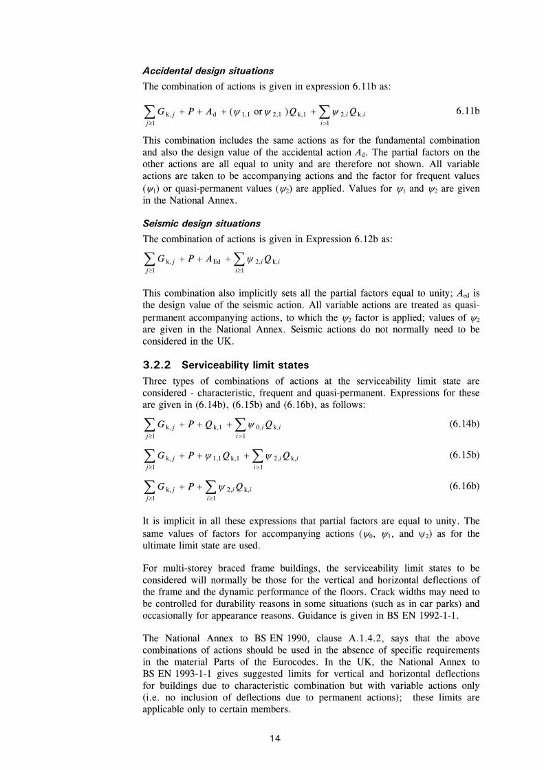
Accidental design situations
The combination of actions is given in expression 6.11b as:
ii
ij
j QQAPG k,1
2,k,12,11,1d1
k, )or(
6.11b
This combination includes the same actions as for the fundamental combination and also the design value of the accidental action Ad. The partial factors on the other actions are all equal to unity and are therefore not shown. All variable actions are taken to be accompanying actions and the factor for frequent values (1) or quasi-permanent values (2) are applied. Values for 1 and 2 are given in the National Annex.
Seismic design situations
The combination of actions is given in Expression 6.12b as:
ii
ij
j QAPG k,1
2,Ed1
k,
This combination also implicitly sets all the partial factors equal to unity; Aed is the design value of the seismic action. All variable actions are treated as quasi-permanent accompanying actions, to which the 2 factor is applied; values of 2 are given in the National Annex. Seismic actions do not normally need to be considered in the UK.
3.2.2 Serviceability limit states Three types of combinations of actions at the serviceability limit state are considered - characteristic, frequent and quasi-permanent. Expressions for these are given in (6.14b), (6.15b) and (6.16b), as follows:
ii
ij
j QQPG k,1
0,k,11
k,
(6.14b)
ii
ij
j QQPG k,1
2,k,11,11
k,
(6.15b)
ii
ij
j QPG k,1
2,1
k,
(6.16b)
It is implicit in all these expressions that partial factors are equal to unity. The same values of factors for accompanying actions (0, 1, and 2) as for the ultimate limit state are used.
For multi-storey braced frame buildings, the serviceability limit states to be considered will normally be those for the vertical and horizontal deflections of the frame and the dynamic performance of the floors. Crack widths may need to be controlled for durability reasons in some situations (such as in car parks) and occasionally for appearance reasons. Guidance is given in BS EN 1992-1-1.
The National Annex to BS EN 1990, clause A.1.4.2, says that the above combinations of actions should be used in the absence of specific requirements in the material Parts of the Eurocodes. In the UK, the National Annex to BS EN 1993-1-1 gives suggested limits for vertical and horizontal deflections for buildings due to characteristic combination but with variable actions only (i.e. no inclusion of deflections due to permanent actions); these limits are applicable only to certain members.

C:\Documents and Settings\faa\My Documents\P365\P365-D09.doc15 Printed 04/11/09
There is no specific direction in either BS EN1990 or the UK National Annex as to which combination of actions is appropriate to the determination of dynamic performance. It is suggested in SCI publication Design of floors for vibration: A new approach (P354)[6] that the quasi-permanent combination is inappropriate and an alternative is offered; consult the publication for further advice.
3.3 Actions Three types of actions (applied loads or imposed deformations) are defined in BS EN1990:
Permanent actions
Variable actions
Accidental actions.
Characteristic values of permanent actions are given in the various Parts of BS EN 1991.
3.3.1 Permanent actions In buildings, the permanent actions are the self weight of the structure, including services, finishes, cladding etc. A permanent action is commonly represented by a single characteristic value Gk. If the variability of the value is not small, two values are used, an upper value Gk,sup (used where the effect is adverse) and a lower value Gk,inf (used where the effect is beneficial).
Characteristic values of permanent actions are given by nominal dimensions and densities; density values are given in 1991-1-1. Typical values of self-weight are shown in Table 3.3.
Table 3.3 Typical self-weights for building elements
Element Typical weight
Precast units (spanning 6 m, designed for a 5 kN/m2 imposed load)
3 to 4.5 kN/m2
Composite slab, normal concrete (130 mm thick, 2400 kg/m3)
2.4 to 3.0 kN/m2
Composite slab, lightweight concrete (130 mm thick 1400 - 1800 kg/m3))
1.9 to 2.3 kN/m2
Services 0.25 kN/m2
Ceilings 0.1 kN/m2
Steelwork (low rise 2 to 6 storeys) 35 to 50 kg/m2
Steelwork (medium rise 7 to 12 storeys) 40 to 70 kg/m2
3.3.2 Variable actions Variable actions on buildings can be subdivided into:
Imposed loads on floors, beams and roofs, arising from occupancy
Wind loads
Snow loads.

C:\Documents and Settings\faa\My Documents\P365\P365-D09.doc16 Printed 04/11/09
The effects of temperature are generally considered not to be significant in orthodox medium rise braced structures.
Imposed loads
Loads on floors
BS EN 1991-1-1 defines categories of use for buildings and assigns characteristic values of uniformly distributed load qk and concentrated load Qk, according to the category. The National Annex to BS EN 1991-1-1 extends the categorisation and gives minimum values of imposed loads for these categories. Table 3.4 shows an extract from the National Annex, for office areas.
Table 3.4 Minimum imposed load for office areas, from Table NA.2 and NA.3 of the National Annex to BS EN 1991-1-1
Category of loaded area
Specific use
Sub-category
Example qk kN/m2
Qk kN
B1 General use other than in B2 2.5 2.7 B
Office areas B2 At or below ground level 3.0 2.7
Where floor areas may be used for storage, the values of imposed load are greater.
Allowance for movable partitions can be included as a uniformly distributed imposed load, providing the floor allows for lateral distribution. This will increase the imposed loads by 0.5 - 1.2 kN/m2 depending on the weight of the panels. See clause 6.3.1.2(8) in BS EN 1991-1-1.
The concentrated loads Qk are applied independently from the distributed loads to check punching or crushing. For concentrated loads, BS EN 1991-1-1, 6.3.1.2(5) states that an ‘appropriate’ area of application is used, this may normally be assumed to be a square area 50 mm by 50 mm. The concentrated loads may also be applied to members at any location, to produce bending moments and shears.
The values given by the UK National Annex are only minimum values and, rather than use such values, or even the values recommended in the BCO guide[1], it is common practice to agree with the client a uniform value for the whole building. A typical value for qk for a commercial office is 4 kN/m2 plus 1 kN/m2, often known as ‘4 plus 1’. The 1 kN/m2 is the allowance for movable partitions. Some designers use ‘5 plus 1’. It is vitally important that the values of imposed loads are agreed at the earliest stage of design and that these are recorded in both the project execution specification and the Health and Safety File for the structure.
Loads on roofs
Table NA.7 in clause NA.2.10 of the National Annex to BS EN 1991-1-1 specifies an imposed load qk of 0.6 kN/m2 and Qk of 0.9 kN on flat roofs (roof slope less than 30) not accessible except for maintenance and repair.
This figure may be exceeded at high altitude, and in the North of the UK, where greater snow load is experienced. BS EN 1991-1-3 must be consulted and the imposed roof load calculated for the actual site location.

C:\Documents and Settings\faa\My Documents\P365\P365-D09.doc17 Printed 04/11/09
Reductions in imposed loads
For the design of floors, beams and roofs, the imposed loads from a single category may be reduced according to the areas supported by the appropriate member by a reduction factor A, according to BS EN 1991-1-1, 6.2.1(4). The reduction factor A is given by NA.2.5 in the National Annex to BS EN 1991-1-1 as:
75.01000
0.1A A
where A is the area (m2) supported.
Where imposed loads from several storeys act on columns and walls the total imposed loads may be reduced, for the design of columns and walls, by a factor n, according to BS EN 1991-1-1, 6.2.2(2). The reduction factor n is given by NA.2.6 in the National Annex to BS EN 1991-1-1 as:
105.0
1056.0
5110
1.1
nfor
nfor
nforn
n
n
n
where n is the number of storeys with loads qualifying for reduction.
Not all imposed floor loads qualify for the reduction described above. Imposed floor loads that do not qualify for the reduction are:
Loads that have been specifically determined from knowledge of the proposed use of the structure. This would be the case if loads other than the general, uniform floor loads given in BS EN 1991-1-1 have been used.
Loads due to plant or machinery.
Loads due to storage.
Wind loads
Wind loads should be determined using BS EN 1991-4 but the UK National Annex must be consulted for buildings in the UK: the NA provides ‘wind maps’ appropriate to the UK and makes significant changes to recommended values and, where permitted, to expressions for determining parameters. The resulting process should be familiar to UK designers as it is similar to that in BS 6399-2.
It is likely that software will become available, as stand-alone commercial packages, that will ease the use of BS EN 1991-1-4 when determining wind loads.
Snow loads
Guidance for determining snow loads is given in BS EN 1991-1- 3, based on snow load maps for the geographic region, and the appropriate National Annex gives additional regional information.

C:\Documents and Settings\faa\My Documents\P365\P365-D09.doc18 Printed 04/11/09
3.3.3 Accidental actions BS EN 1991-1-7 gives guidance on the evaluation of accidental actions and on procedures for risk analysis and measures to reduce the consequences of an accident that would cause structural damage. Accidental actions include a range of applied loadings and thermal actions due to fire.
Snow loads
For certain roof shapes, exceptional snow drifting needs to be considered and these loads are treated as accidental actions. Guidance is given in Annex B of BS EN 1991-1-3.
Impact loading
Values for accidental impact loads on buildings are given in BS EN 1991-1-7.
Explosion loading
Guidance on determining accidental loading due to explosion is given in BS EN 1991-1-7, although there are no rules for determining specific values of accidental actions.
Thermal actions
Thermal actions due to fire will normally be based on the appropriate time-temperature curve for the ‘standard fire’, as given in BS EN 1991-1-2. In some cases, such as for buildings with sprinklers or occupancies such as offices or assembly buildings, it may be possible to obtain less onerous thermal actions from the ‘parametric fire’ curve, given in Annex A of BS EN 1991-1-2. It should be noted however that some additional knowledge is required to apply this technique (see guidance in Steel building design: Fire resistant design (P375)[50]).

C:\Documents and Settings\faa\My Documents\P365\P365-D09.doc19 Printed 04/11/09
4 GLOBAL ANALYSIS OF BRACED FRAMES
4.1 Simple construction The vast majority of multi-storey braced frames in the UK are designed as ‘simple construction’, for which the global analysis assumes nominally pinned connections between beams and columns; resistance to horizontal forces is provided by bracing systems or cores. Consequently, the beams are designed as simply supported and the columns are designed only for moments arising from a nominal eccentricity of connection of the beam to the column (in conjunction with the axial forces). As a further consequence, it is not necessary to consider pattern loading to derive design forces in the columns.
This design approach is accommodated by the Eurocodes. A ‘simple’ joint model, in which the joint may be assumed not to transmit bending moments, may be used if the joint is classified as ‘nominally pinned’ according to BS EN 1993-1-8, 5.2.2 and this classification may be based on previous satisfactory performance in similar cases. The joint configurations commonly used in the UK, which assume a pinned connection but also assume that the beam reactions are applied eccentrically to the columns, have that evidence of satisfactory performance.
For braced frames designed in accordance with BS EN 1993-1-1, the global analysis model may therefore assume pinned connections between the columns and the beams, provided that the columns are designed for the bending moments due to eccentric reactions from the beams (see Section 6.2).
4.2 Bracing systems In a multi-storey building, the beams and columns are generally arranged in an orthogonal pattern in both elevation and on plan. In a braced frame building, the resistance to horizontal forces is provided by two orthogonal bracing systems:
Vertical bracing. Bracing in vertical planes (between lines of columns) provides load paths to transfer horizontal forces to ground level and provide a stiff resistance against overall sway.
Horizontal bracing. At each floor level, bracing in a horizontal plane, generally provided by floor plate action, provides a load path to transfer the horizontal forces (mainly from the perimeter columns, due to wind pressure on the cladding) to the planes of vertical bracing.
As a minimum, three vertical planes of bracing are needed, to provide resistance in both directions in plan and to provide resistance to torsion about a vertical axis. In practice, more than three are usually provided, for example in the locations shown diagrammatically in Figure 4.1.

C:\Documents and Settings\faa\My Documents\P365\P365-D09.doc20 Printed 04/11/09
Assuming that the horizontal bracing system at each floor level is relatively stiff (which is the case when the floor acts as a diaphragm), the forces carried by each plane of vertical bracing depend on its relative stiffness and location, and on the location of the centre of pressure of the horizontal forces (see further discussion on location of vertical bracing planes, below).
Note that, to avoid disproportionate collapse (see discussion on robustness in Section 8), at least two planes of vertical bracing in each orthogonal direction must be provided. No substantial part of the structure should be braced by only one plane of bracing in the direction being considered because if the local failure were to occur in one of its members there would be no other restraint system in that direction. Thus, for buildings designed to avoid disproportionate collapse, the bracing arrangement in Figure 4.2 would not be satisfactory.
The functions of vertical bracing system can be provided partially or entirely by one or more reinforced concrete or Corefast[15] cores, but such an arrangement is outside the scope of this publication.
Location of planes of vertical bracing
It is preferable to locate bracing at or near the extremities of the structure, in order to resist any torsional effects. Where the sets of bracing are identical or similar, it is sufficient to assume that the horizontal forces (wind loads and equivalent horizontal forces, each magnified for second order effects, see discussion below) are shared equally between the bracing systems in the orthogonal direction under consideration.
Where the stiffnesses of the vertical bracing systems differ or the bracing systems are located asymmetrically on plan, as shown in Figure 4.3, equal sharing of forces should not be assumed. The forces carried by each bracing system can be calculated by assuming the floor is a stiff beam and the bracing systems are spring supports, as shown in Figure 4.3.
Vertical bracing
Figure 4.1 Typical arrangement of vertical bracing
Y
X
3 sets of bracing in Y direction1 set of bracing in X direction
Figure 4.2 Unsatisfactory bracing arrangement if disproportionate
collapse is to be avoided

C:\Documents and Settings\faa\My Documents\P365\P365-D09.doc21 Printed 04/11/09
The stiffness of each bracing system should be calculated by applying horizontal forces to each bracing system and calculating the deflection. The spring stiffness (typically in mm/kN) can then be used to calculate the distribution of forces to each bracing system.
Forces due to wind loads
In all cases, the externally applied horizontal force at each floor level is that due to wind load over the face of the building from half a storey above to half a storey below the floor level being considered, as shown for both floors and roof in Figure 4.4.
Verticalbracing
Centre of pressure of wind and equivalent horizontal forces
Stiff beam
Springsupports
Figure 4.3 Determination of bracing forces for asymmetric arrangement of bracing
=
=
=
=
=
=
Wind load carried byroof truss
Wind load carried byfloor
Figure 4.4 Nominal allocation of wind load to floors and roof

C:\Documents and Settings\faa\My Documents\P365\P365-D09.doc22 Printed 04/11/09
4.3 Vertical bracing In a braced frame multi-storey building, the planes of vertical bracing are usually provided by diagonal bracing between two lines of columns, as shown in Figure 4.5. Either single diagonals are provided, as shown, in which case they must be designed for either tension or compression, or crossed diagonals are provided, in which case slender bracing members that do not resist compressive forces can be used (then only the tensile diagonals provide the resistance).
Note that when crossed diagonals are used and it is assumed that only the tensile diagonals provide resistance, the floor beams participate as part of the bracing system (in effect a vertical Pratt truss is created, with diagonals in tension and posts in compression).
The vertical bracing must be designed to resist the forces due to the following:
Wind loads
Equivalent horizontal forces, representing the effect of initial imperfections
Second order effects due to sway (if the frame is flexible).
Guidance on the determination of equivalent horizontal forces is given in Section 4.5.1 and on the consideration of second order effects in Section 4.7.
Forces in the individual members of the bracing system must be determined for the appropriate combinations of actions (see Section 3.2). For bracing members, design forces at ULS due to the combination where wind load is the leading action are likely to be the most onerous.
Where possible, bracing members inclined at approximately 45° are recommended. This provides an efficient system with relatively modest member forces compared to other arrangements, and means that the connection details where the bracing meets the beam/column junctions are compact. Narrow bracing systems with steeply inclined internal members will increase the sway sensitivity of the structure. Wide bracing systems will result in more stable structures.
H
Horizontal forces
H
Figure 4.5 Cantilever truss

C:\Documents and Settings\faa\My Documents\P365\P365-D09.doc23 Printed 04/11/09
Table 4.1 gives an indication of how maximum deflection varies with bracing layout, for a constant size of bracing cross section.
Table 4.1 Bracing efficiency
Storey Height Bracing width Angle from horizontal
Ratio of maximum deflection (compared to
bracing at 34°)
h 2h 26° 0.9
h 1.5h 34° 1.0
h h 45° 1.5
h 0.75h 53° 2.2
h 0.5h 63° 4.5
4.4 Horizontal bracing A horizontal bracing system is needed at each floor level, to transfer horizontal forces (chiefly the forces transferred from the ends of perimeter columns) to the planes of vertical bracing that provide resistance to horizontal forces.
There are two types of horizontal bracing system that are used in multi-storey braced frames:
Diaphragms
Discrete triangulated bracing.
Usually, the floor system will be sufficient to act as a diaphragm without the need for additional steel bracing. At roof level, bracing, often known as a wind girder, may be required to carry the horizontal forces at the top of the columns, if there is no slab.
4.4.1 Horizontal diaphragms All floor solutions involving permanent formwork such as metal decking fixed by through-deck stud welding to the beams, with in-situ concrete infill, provide an excellent rigid diaphragm to carry horizontal forces to the bracing system.
Floor systems involving precast concrete planks require proper consideration to ensure adequate transfer of forces if they are to act as a diaphragm. The coefficient of friction between planks and steelwork may be as low as 0.1, and even lower if the steel is painted. This will allow the slabs to move relative to each other, and to slide over the steelwork. Grouting between the slabs will only partially overcome this problem, and for large shears, a more positive tying system will be required between the slabs and from the slabs to the steelwork.
Connection between planks may be achieved by reinforcement in the topping. This may be mesh, or ties may be placed along both ends of a set of planks to ensure the whole panel acts as one. Typically, a 10 mm bar at half depth of the topping will be satisfactory.
Connection to the steelwork may be achieved by one of two methods:
Enclose the slabs by a steel frame (on shelf angles, or specially provided constraint) and fill the gap with concrete.
C:\Documents and Settings\faa\My Documents\P365\P365-D09.doc24 Printed 04/11/09
Provide ties between the topping and an in-situ topping to the steelwork (known as an ‘edge strip’). Provide the steel beam with some form of shear connectors to transfer forces between the in-situ edge strip and the steelwork.
If plan diaphragm forces are transferred to the steelwork via direct bearing (typically the slab may bear on the face of a column), the capacity of the connection should be checked. The capacity is generally limited by local crushing of the plank. In every case, the gap between the plank and the steel should be made good with in-situ concrete.
Timber floors and floors constructed from precast concreted inverted tee beams and infill blocks (often known as ‘beam and pot’ floors) are not considered to provide an adequate diaphragm without special measures.
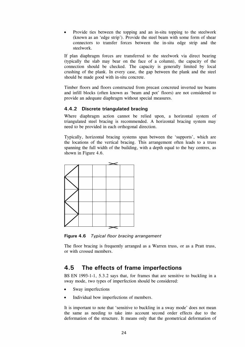
4.4.2 Discrete triangulated bracing Where diaphragm action cannot be relied upon, a horizontal system of triangulated steel bracing is recommended. A horizontal bracing system may need to be provided in each orthogonal direction.
Typically, horizontal bracing systems span between the ‘supports’, which are the locations of the vertical bracing. This arrangement often leads to a truss spanning the full width of the building, with a depth equal to the bay centres, as shown in Figure 4.6.
The floor bracing is frequently arranged as a Warren truss, or as a Pratt truss, or with crossed members.
4.5 The effects of frame imperfections BS EN 1993-1-1, 5.3.2 says that, for frames that are sensitive to buckling in a sway mode, two types of imperfection should be considered:
Sway imperfections
Individual bow imperfections of members.
It is important to note that ‘sensitive to buckling in a sway mode’ does not mean the same as needing to take into account second order effects due to the deformation of the structure. It means only that the geometrical deformation of
Figure 4.6 Typical floor bracing arrangement

C:\Documents and Settings\faa\My Documents\P365\P365-D09.doc25 Printed 04/11/09
the structure gives rise to additional effects in the members that must be taken into account in design. These additional effects may be only first order effects. If the geometrical deformation significantly affects the structural behaviour then second order effects also need to be considered; this is discussed in Section 4.7.
4.5.1 Sway imperfections The global sway imperfections to be considered are shown in BS EN 1993-1-1 Figure 5.2, reproduced below as Figure 4.7.
The basic imperfection that is allowed for is an out-of-verticality 0 of 1/200. This allowance is greater than normally specified tolerances because it allows both for actual values exceeding specified limits and for residual effects such as lack of fit.
The design allowance in BS EN 1993-1-1, 5.3.2 is given by:
mhmh0200
1
where h is a reduction factor for the overall height and m is a reduction factor which according to the Eurocode depends on the number of columns in a row. (For detailed definition, see 5.3.2(3).) This presumes that every row has bracing. More generally m should be calculated according to the number of columns stabilized by the bracing system – generally from several rows.
For simplicity, the value of may conservatively be taken as 1/200, irrespective of the height and number of columns.
Where, for each storey, the externally applied horizontal force exceeds 15% of the total vertical force, sway imperfections may be neglected (because they have little influence on sway deformation and amplification factor).
Equivalent horizontal forces
BS EN 1993-1-1, 5.3.2(7) states that vertical sway imperfections may be replaced by systems of equivalent horizontal forces, introduced for each column. It is much easier to use equivalent horizontal forces than to introduce the geometric imperfection into the model. This is because:
The imperfection must be tried in each direction to find the greater effect and it is easier to apply loads than modify geometry
Applying forces gives no problems of changes in length that would occur when inclining the columns of buildings in which the column bases are at different levels.
h h
Figure 4.7 Equivalent sway imperfections (taken from BS EN 1993-1-1
Figure 5.2)

C:\Documents and Settings\faa\My Documents\P365\P365-D09.doc26 Printed 04/11/09
According to 5.3.2(7) the equivalent horizontal forces have the design value of NEd at the top and bottom of each column, where NEd is the force in each column; the forces at each end are in opposite directions. For design of the frame, it is much easier to consider the net equivalent force at each floor level. Thus an equivalent horizontal force equal to times the total vertical design force applied at that floor level should be applied at each floor and roof level.
4.6 Additional design cases for bracing systems The bracing system must carry the externally applied loads, together with the equivalent horizontal forces. In addition, the bracing must be checked for two further design situations which are local to the floor level:
Horizontal forces to floor diaphragms (see Section 4.6.1)
Forces due to imperfections at splices (see Section 4.6.2).
In both these design situations, the bracing system is checked locally (the storeys above and below) for the combination of the force due to external loads together with the forces due to either of the above imperfections. The equivalent horizontal forces modelled to account for frame sway (section 4.5.1) are not included in either of these combinations. Only one imperfection needs to be considered at a time.
The horizontal forces to be considered are the accumulation of all the forces at the level being considered, divided amongst the bracing systems.
It is normal practice in the UK to check these forces without co-existent beam shears. The justification is that the probability of maximum beam shear plus maximum imperfections together with minimum connection resistance is beyond the design probability of the design code.
4.6.1 Forces transferred to floor diaphragms For the determination of the horizontal forces transferred to floor diaphragms, the configuration of imperfection to be considered is with the direction of the imperfection reversing at that floor level. BS EN 1993-1-1, 5.3.2(5) states that the appropriate imperfection is then as shown in Figure 4.8. These horizontal forces must be transferred to the bracing systems.
Ed Ed
Ed Ed
Ed
i i
/2
/2
h
h
h
N
N
H = N
N
H = N
Figure 4.8 Configuration of sway imperfection for horizontal forces
on floor diaphragm (taken from BS EN 1993-1-1 Figure 5.3)

C:\Documents and Settings\faa\My Documents\P365\P365-D09.doc27 Printed 04/11/09
The figure shows two cases, both of which give rise to a horizontal shear force of NEd. Note that in this case the value of is calculated using a value of h that is appropriate to the height of only a single storey and that, since the value of NEd is different above and below the floor, the larger value (i.e. that for the lower storey) should be used.
4.6.2 Effects due to imperfections at splices Clause 5.3.3 of BS EN 1993-1-1 states that imperfections in the bracing system should also be considered. Whereas most of the clause is applicable to bracing systems restraining members in compression, such as chords of trusses, the guidance on forces at splices in 5.3.3(4) should be followed.
The lateral force at a splice should be taken as mNEd/100, and this must be resisted by the local bracing members in addition to the forces from externally applied actions such as wind load, but excluding the equivalent horizontal forces. The force to be carried locally is the summation from all the splices at that level, distributed amongst the bracing systems. If many heavily-loaded columns are spliced at the same level, the force could be significant. Assuming that a splice is nominally at a floor level, only the bracing members between that floor and the floors above and below need to be checked for this additional force. This is shown in Figure 4.9.
This additional force should not be used in the design of the overall bracing system, and is not taken to the foundations, unless the splice is at the first storey. When designing the bracing system, only one imperfection needs to be considered at a time. When checking the bracing for the additional forces due to imperfections at splices, the equivalent horizontal forces should not be applied to the bracing system.
As the force may be in either direction, it is advised that the simplest approach is to divide the force into components (in the case above, into the two diagonal members) and check each member for the additional force. Note that the values of the imperfection forces and the forces in the members due to wind load vary depending on the combination of actions being considered.
Level ofsplices
Local members to bechecked for additionalforce arising from(in this case) 5 splicesper row
Figure 4.9 Bracing members to be checked at splice levels
C:\Documents and Settings\faa\My Documents\P365\P365-D09.doc28 Printed 04/11/09
4.6.3 Member bow imperfections In a braced frame with simple connections, no allowance is needed in the global analysis for bow imperfections in members because they do not influence the global behaviour and are taken into account in the design of compression members through the use of buckling curves.
Should moment-resisting connections be assumed in the frame design, bow imperfections may need to be allowed for - see BS EN 1993-1-1, 5.3.2(6).
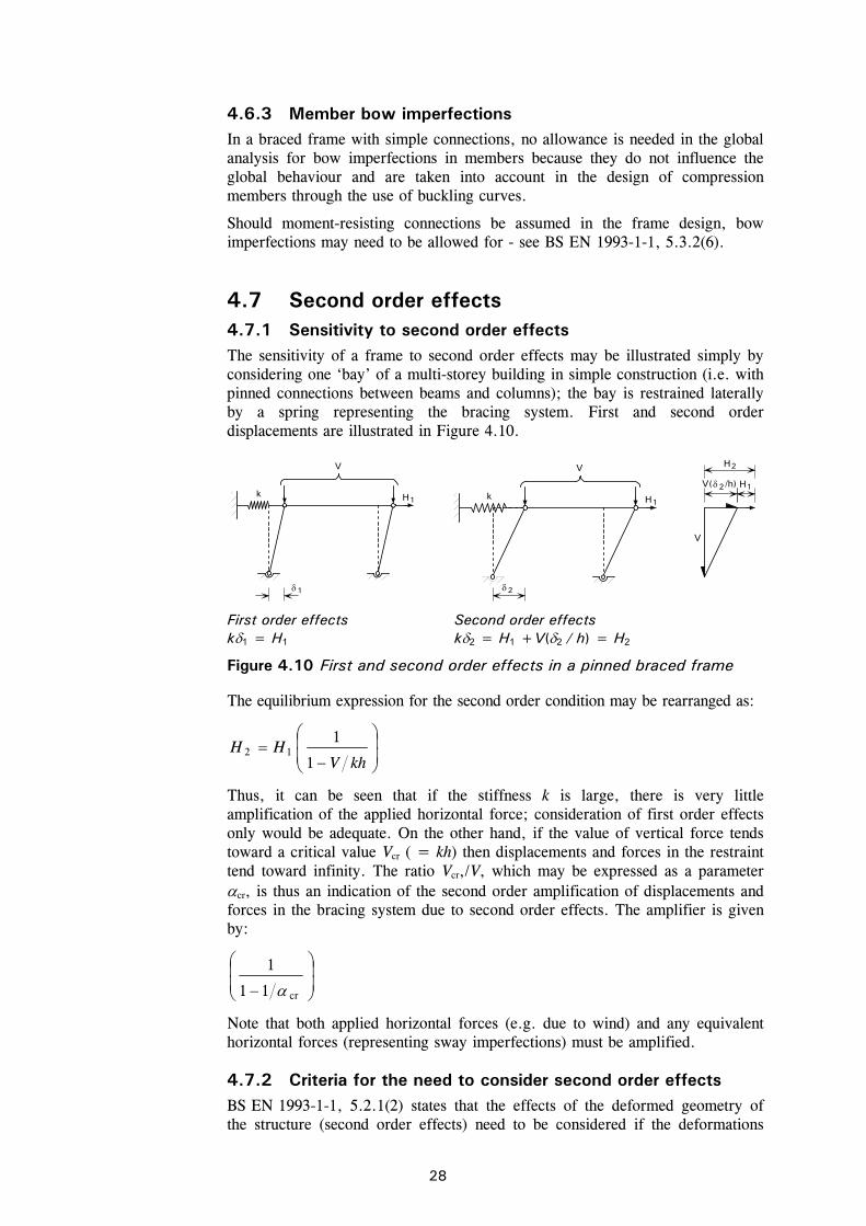
4.7 Second order effects 4.7.1 Sensitivity to second order effects The sensitivity of a frame to second order effects may be illustrated simply by considering one ‘bay’ of a multi-storey building in simple construction (i.e. with pinned connections between beams and columns); the bay is restrained laterally by a spring representing the bracing system. First and second order displacements are illustrated in Figure 4.10.
The equilibrium expression for the second order condition may be rearranged as:
khVHH
1
112
Thus, it can be seen that if the stiffness k is large, there is very little amplification of the applied horizontal force; consideration of first order effects only would be adequate. On the other hand, if the value of vertical force tends toward a critical value Vcr ( = kh) then displacements and forces in the restraint tend toward infinity. The ratio Vcr,/V, which may be expressed as a parameter cr, is thus an indication of the second order amplification of displacements and forces in the bracing system due to second order effects. The amplifier is given by:
cr11
1
Note that both applied horizontal forces (e.g. due to wind) and any equivalent horizontal forces (representing sway imperfections) must be amplified.
4.7.2 Criteria for the need to consider second order effects BS EN 1993-1-1, 5.2.1(2) states that the effects of the deformed geometry of the structure (second order effects) need to be considered if the deformations
First order effects
k1 = H1 Second order effects k2 = H1 +V(2 / h) = H2
Figure 4.10 First and second order effects in a pinned braced frame
V
H1k
V
H12
H2
2
V( /h)
V
k H1
1

C:\Documents and Settings\faa\My Documents\P365\P365-D09.doc29 Printed 04/11/09
significantly increase the forces in the structure or if the deformations significantly modify structural behaviour. For elastic global analysis, 5.2.1 says that the second order effects are significant if the parameter cr < 10, where cr is determined by first order analysis and for a braced frame is defined by the approximate expression:
EdH,Ed
Edcr
h
V
H
where:
HEd is the design value of the horizontal reaction at the bottom of the storey to the horizontal loads and the equivalent horizontal forces1 (see further discussion in Section 4.7.4)
VEd is the total design vertical force on the structure on the bottom of the storey
H,Ed is the horizontal displacement at the top of the storey, relative to the bottom of the storey, when the frame is loaded with horizontal loads (e.g. wind) and equivalent horizontal forces which are applied at each floor level
h is the storey height.
The above expression for cr is not restricted to use in simple construction - in fact the notation given in BS EN 1993-1-1, Figure 5.1 is shown for the sway deformation of a rigid-jointed ‘bay’.
The criterion should be applied separately for each storey, for the condition where the full frame is loaded, as shown in Figure 4.11. In most cases, the lowest storey will give the lowest value of cr.
There is a note to 5.2.1(4)B to say that the above expression for cr is only valid where the ‘compression in the beams or rafters is not significant’. This limitation is intended principally for unbraced frames. In multi-storey braced frames the forces in the beams are normally small in relation to their flexural
1 The 2005 published version of EN 1993-1-1 refers to ‘fictitious horizontal loads’ but these are the same as the ‘equivalent horizontal forces’ in 5.3.2(7).
Total appliedhorizontal loads(wind + EHF)
Vertical loadson roof and floors(permanent and variable)
Figure 4.11 Horizontal forces applied to the bracing system

C:\Documents and Settings\faa\My Documents\P365\P365-D09.doc30 Printed 04/11/09
buckling resistance and thus their deformations do not affect the sway stiffness of the frame.
4.7.3 Methods for determining second order effects Where second order effects need to be evaluated, BS EN 1993-1-1, 5.2.2 says that they may be allowed for by:
An appropriate second-order analysis, taking into account the influence of the deformation of the structure.
Using appropriate (increased) buckling lengths of members.
Amplification of an elastic first order analysis using the initial geometry of the structure.
The use of second order analysis is discussed in Section 4.7.6 below.
The use of increased column buckling effective lengths is generally not recommended, simply because of the manual effort involved in calculating the effective length factors. However, if this option is chosen, effective length factors can be determined using a source of non-conflicting complementary information (NCCI), such as BS 5950 Annex E or DD ENV 1993-1-1 Annex E.
Use of amplified first order effects is subject to the limitation that cr 3 (if cr is less than 3, second order analysis must be used).
Application of amplifier
The amplification factor is given in BS EN 1993-1-1, 5.2.2(5)B as:
cr11
1
which is the same as given in Section 4.7.1.
Only the effects due to the horizontal forces (including the equivalent horizontal forces) need to be amplified. In a braced frame, where the beam to column connections are pinned and thus do not contribute to lateral stiffness, the only effects to be amplified are the axial forces in the bracing members and the forces in columns that are due to their function as part of the bracing system.
4.7.4 Combinations of actions for global analysis
The determination of the value of cr depends on design values of vertical and horizontal actions (loads) and thus depends on the relative magnitudes of these two groups of actions. This means that cr must be determined separately for each combination of actions (notably for the different cases where wind load is the leading action and where the wind load is an accompanying action). It also means that a frame might not be sway sensitive in one combination yet sway sensitive in another.
4.7.5 Example of sway deformation calculations A worked example of the design of bracing in a multi-storey braced frame is given in Appendix A of this publication.

C:\Documents and Settings\faa\My Documents\P365\P365-D09.doc31 Printed 04/11/09
4.7.6 Second-order analysis A range of second order analysis software is available. Use of any software will give results that are to some extent approximate, depending on the solution method employed, the types of second-order effects considered and the modelling assumptions. Generally, second-order software will automatically allow for frame imperfections, so the designer will not need to calculate and apply the equivalent horizontal forces. The effects of deformed geometry (second-order effects) will be allowed for in the analysis. The effect of member imperfections and such things as residual stresses are allowed for if verifying members in accordance with the rules in Section 6 of BS EN 1993-1-1.
4.8 Summary design process for bracing systems The following simple design process is recommended. If designing manually, use the design data in publication P363, Steel building design: Design data[48] to choose appropriate section sizes.
1. Choose appropriate section sizes for the beams.
2. Choose appropriate section sizes for the columns (which may be designed initially for axial force alone, leaving some nominal provision for bending moments, to be determined at a later stage).
3. Calculate the equivalent horizontal forces (EHF), floor by floor, and the wind loads.
4. Calculate the total shear at the base of the bracing, by adding the total wind load to the total EHF, and sharing this appropriately amongst the bracing systems.
5. Size the bracing members. The lowest bracing member (with the greatest design force) can be sized, based on the shear determined in Step 4. A smaller section size may be used higher up the structure (where the bracing is subject to lesser forces) or the same size may be used for all members.
6. Evaluate the frame stability, in terms of the parameter cr, using the combination of the EHF and wind loads as the horizontal forces on the frame, in conjunction with the vertical loads.
7. Determine an amplifier, if required (i.e. if cr < 10). If the frame is sensitive to second order effects, all the lateral forces must be amplified. If this is the case, the bracing members may need to be re-checked for increased forces (step 5).
8. At each floor level, check that the connection to the diaphragm can carry 1% of the axial force in the column at that point (clearly, the most onerous design force is at the lowest suspended floor).
9. Verify that the floor diaphragms are effective in distributing all forces to the bracing systems.
10. At splice levels, determine the total force to be resisted by the bracing locally (which will usually be the summation from several columns). Verify that the bracing local to the splice can carry these forces in addition to the forces due to external loads (EHF are not included when making this check).
11. Verify that the bracing local to each floor can carry the restraint forces from that floor, in addition to the forces due to external loads (EHF are not included when making this check).

C:\Documents and Settings\faa\My Documents\P365\P365-D09.doc32 Printed 04/11/09
5 FLOOR SYSTEMS
In addition to their obvious load-carrying function, structural floors often act as horizontal diaphragms, ensuring forces due to horizontal loads are carried to the vertical bracing. Floor components (the floor slab, deck units and the beams) will also require a certain fire resistance, as described in Section 9. Services may be integrated with the floor construction, or like the ceiling, simply suspended below the floor. Structural floors may have a directly-fixed floor finish, or may have a screed, or a raised secondary floor above the structure. Raised floors allow services (particularly electrical and communication services) to be distributed easily around highly serviced accommodation.
This Section briefly describes seven floor systems often used in multi-storey buildings. A brief description of each floor system is presented together with the advantages of each system.
Further information on these systems is given in the references and in manufacturer’s literature and software. (Note that at the time of publication, software is generally only available for design to BS 5950.)
The following floor systems are covered:
Short-span composite beams and composite slabs with metal decking.
Slimdek®.
Cellular composite beams with composite slabs and steel decking.
Slimflor® beams with precast concrete units.
Long-span composite beams and composite slabs with metal decking.
Composite beams with precast concrete units.
Non-composite beams with precast concrete units.
Design resistances for the various floor systems need to be verified in accordance with BS EN 1993-1-1 or BS EN 1994-1-1, as appropriate.
Composite construction
For composite construction, the decking profile and the type of concrete need to be specified.
Decking may have a re-entrant or trapezoidal profile. Re-entrant decking uses more concrete than trapezoidal decking, but has increased fire resistance for a given slab depth. Trapezoidal decking generally spans further than re-entrant decking, but the shear stud resistance is less with trapezoidal decking than with re-entrant decking.
Generally, lightweight aggregate concrete is proposed in this document, unless a directly-bonded floor is specified. Designers should note that lightweight aggregate concrete is usually more expensive than normal concrete, and may not be available in all areas of the country. Ideally, the choice of concrete should be made in conjunction with the Main Contractor, in order to produce an optimum scheme.
Note that all references to concrete grades relate to the grade designation according to BS EN 1992-1-1. A typical designation for normal concrete is C30/37, where ‘30’ indicates the specified cylinder strength (which is used as characteristic strength) and ‘37’ indicates the cube strength. A typical designation for lightweight aggregate concrete is LC30/33.

C:\Documents and Settings\faa\My Documents\P365\P365-D09.doc33 Printed 04/11/09
5.1 Short-span composite beams and composite slabs with metal decking
Description This floor system consists of downstand steel beams with shear connectors welded to the top flange to enable the beam to act compositely with an in-situ composite floor slab.
Framing arrangements normally involve the slab spanning 3 to 4 m to secondary beams, which are in turn supported by primary beams. Secondary and primary beams are usually composite. Edge beams are often non-composite.
The floor slab comprises a shallow ribbed metal decking and a concrete topping, which act together compositely. Slabs are typically 130 mm thick and the decking about 60 mm deep in galvanized strip, with an overall thickness of 0.9 to 1.2 mm. Unprotected slabs may need to be thicker, depending on the fire resistance period.
The shear connectors are normally site-welded through the decking to provide a strong fixing to the beam, and may enable the decking to provide restraint to the beam during the construction stage when the concrete is being poured. The studs may also be pre-welded to the beams but there are disadvantages of this: BS EN 1994-1-1 then requires a reduction of the design resistance of the stud; holes have to be pre-cut in the decking, which is extra work and it complicates positioning of the decking.
Mesh reinforcement is placed in the slab to reduce cracking, to help spread localised loads, to act as shear reinforcement around the shear connectors and to enhance the fire resistance of the slab.
The decking is normally designed to support the wet weight of the concrete and construction loading as a continuous member over at least two spans, but the composite slab is normally designed as simply supported between beams (but some continuity reinforcement is required). For fire conditions, the slab is normally designed as continuous over the supports and for this situation continuity mesh should be provided.
Typical beam span range
Secondary beams (orthogonal to decking): 6.0 m to 7.5 m at 3 to 4 m spacing.
Primary beams (parallel to decking): 6.0 m to 9.0 m.
Main design considerations
for the floor layout
Secondary beams should be spaced closely enough to avoid propping the decking, as propping can be expensive and disruptive on site.
Services will need to pass under beams, and thus affect the overall floor zone.
Overall floor zone may be governed by depth of edge beams. They may need to be deeper than internal beams because of more onerous serviceability criteria in supporting the cladding. Also, whilst the use of non-composite edge beams avoids the need for detailing special U-bars around the shear connectors (although studs and U-bars may be needed for robustness requirements), the beams will be deeper than a composite member.
Advantages Shallower beams than non-composite construction, lightweight, economic.
Disadvantages More columns needed than with long-span systems.
Deeper overall floor zone than shallow floor systems.
Generally, beams require fire protection.
Services integration
Main heating and ventilation units can be positioned between beams, but ducts must pass below beams. Small services may be taken through discrete holes in the web up to 150 mm diameter, where beam strength will allow.
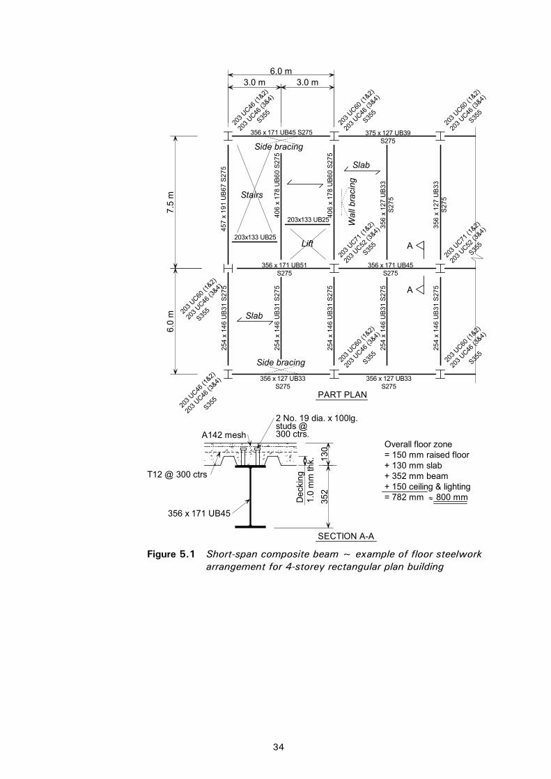
C:\Documents and Settings\faa\My Documents\P365\P365-D09.doc34 Printed 04/11/09
6.0 m
6.0
m7.
5 m
3.0 m 3.0 m
130
352
SECTION A-A
PART PLAN
= 150 mm raised floor
Stairs
Side bracing
Side bracing
Slab
Wal
l bra
cing
203
UC60 (1
&2)
203
UC60 (1
&2)
203
UC46 (1
&2)
203
UC46 (1
&2)
203
UC46 (3
&4)
203
UC60 (1
&2)
203
UC60 (1
&2)
203
UC71 (1
&2)
203
UC71 (1
&2)
203
UC52 (3
&4)
203
UC52 (3
&4)
203
UC46 (3
&4)
203
UC46 (3
&4)
203
UC46 (3
&4)
203
UC46 (3
&4)
203
UC46 (3
&4)
203x133 UB25
203x133 UB25
A
A
Slab
35
6 x
12
7 U
B3
3S
27
5
35
6 x
12
7 U
B3
3S
27
5
203
UC46 (3
&4)
203
UC60 (1
&2)
375 x 127 UB39S275
356 x 171 UB51S275
356 x 171 UB45S275
356 x 127 UB33S275
356 x 127 UB33S275
+ 130 mm slab+ 352 mm beam
S355
S355
S355
S355
S355
S355
S355
S355
25
4 x
14
6 U
B3
1 S
27
5
25
4 x
14
6 U
B3
1 S
27
5
25
4 x
14
6 U
B3
1 S
27
5
25
4 x
14
6 U
B3
1 S
27
5
25
4 x
14
6 U
B3
1 S
27
5
40
6 x
17
8 U
B6
0 S
27
5
40
6 x
17
8 U
B6
0 S
27
5
356 x 171 UB45 S275
45
7 x
19
1 U
B6
7 S
27
5
+ 150 ceiling & lighting
Lift
Overall floor zone
Dec
king
1.0
mm
thk.
S355
356 x 171 UB45
2 No. 19 dia. x 100lg.studs @300 ctrs.A142 mesh
T12 @ 300 ctrs
= 782 mm 800 mm
Figure 5.1 Short-span composite beam ~ example of floor steelwork
arrangement for 4-storey rectangular plan building

C:\Documents and Settings\faa\My Documents\P365\P365-D09.doc35 Printed 04/11/09
Governing design criteria for
beams
Total deflections will usually govern for S355 secondary beams. Strength will usually govern for all S275 beams and for all primary beams.
When serviceability criteria govern, consider S275 sections, which are cheaper than S355 sections.
Governing design criteria for
decking/slab
Strength or deflection of the decking in the construction condition.
Fire resistance (affects concrete cover to the decking and mesh reinforcement size).
Strength or deflection in the composite condition.
Design approach 1. Assume secondary beams at 3 – 3.75 m spacing, on a 6 m, 7.5 m or 9 m grid.
2. Choose decking and slab, using decking manufacturer’s design tables or software. Assume LWAC, unless there is a directly-bonded floor covering. Assume LC35/38 concrete, and unpropped decking during construction. Ensure chosen slab and reinforcement meet the fire resistance required.
3. Design beams using software. Try studs at approximately 300 mm spacing for secondary beams (to suit trough spacings), and at 150 mm spacing on primary beams. Note that the orientation of the decking will differ between secondary and primary beams.
Typical section sizes
Composite beam depth (steel beam plus slab) span/16 to span/18 254 146 UB31 S275 for 6 m at 3.0 m spacing (secondary beam) 305 165 UB40 S355 for 7.5 m at 3.75 m spacing (secondary beam) 356 171 UB57 S355 for 7.5 m at 7.5 m spacing. (primary beam) Usually one serial size deeper or one weight heavier for edge beams
Grade of steel Secondary beam and edge beams: Usually S275.
Primary beam: Either S275 or S355.
Overall floor zone
Typically, 1200 mm for 7.5 m grid with 150 mm raised floor and air conditioning. Typically 700 mm for a 6 m grid without services.
Raised floor
Fan CoilUnit
150
50
LightingCeiling
Ducting + insulation 400
5050
130
1200 mm
360
Figure 5.2 Overall floor zone ~ typical short-span composite construction

C:\Documents and Settings\faa\My Documents\P365\P365-D09.doc36 Printed 04/11/09
Type of concrete Either normal concrete, 2400 kg/m3, or lightweight aggregate concrete (LWAC), typically density class D1.8 to BS EN 206-1 (1600-1800 kg/m3) can be used.
Normal concrete has better sound reduction, so is better for residential buildings, hospitals, etc.
LWAC is better for overall building weight/foundation design, better span capability of slab, and has better fire insulating properties, enabling slightly thinner slabs (10 mm less) to be used. It is not available in all parts of the UK. LWAC is not considered suitable for directly-bonded floor coverings.
Grade of concrete
Use LC25/28 or C25/30 as a minimum. Use LC40/44 or C35/45 if concrete is to be used as a wearing surface.
Fire protection Beams (typically): Either Intumescent coating up to 1.5 mm thick for up to 90 minutes , or Board 15 - 25 mm thick for up to 90 minutes Note: P288[16] gives a design method and describes how beams may be left
unprotected in certain areas.
Columns (typically): Board 15 mm thick for up to 60 minutes Board 25 mm thick for 90 minutes
Connections Simple (non-moment resisting) connections: double angle cleats, partial depth flexible endplates or finplates.
Design guidance For choice of decking and composite slab design (including fire resistance); manufacturer’s design tables.
For best practice advice in design and construction, refer to P300[17]
For design charts and worked example for decking and beams, refer to P055[18]
For fire protection, refer to the ‘Yellow book’[19]
Software Slab design: Comdek software, available from www.corusconstruction.com Deckspan software, available from www.rlsd.com/ Multideck software, available from www.kingspanmetlcon.com/services/software/index.htm
Beam design: BDES software, available from www.corusconstruction.com

C:\Documents and Settings\faa\My Documents\P365\P365-D09.doc37 Printed 04/11/09
5.2 Slimdek Description Slimdek is a shallow floor system comprising asymmetric floor beams (ASBs)
supporting heavily ribbed composite slabs with 225 mm deep decking. ASBs are proprietary beams with a wider bottom flange than top. The section has embossments rolled into the top flange and acts compositely with the floor slab without the need for additional shear connectors. The decking spans between the bottom flanges of the beams and acts as permanent formwork to support the slab and other loads during construction. The in-situ concrete acts compositely with the decking and encases the beams so that they lie within the slab depth – apart from the exposed bottom flange.
Span arrangements are normally within a 6-9 m grid, with a slab depth of 280-350 mm. Decking requires propping at the construction stage for spans beyond about 6 m. Reinforcing bars (16–25 mm dia) need to be included in the ribs of the slab to give sufficient strength in the fire condition. The reinforcing bars also improve the composite floor strength in the normal condition.
Edge beams can be RHS Slimflor beams, which comprise a rectangular or square rolled hollow section with a flange plate welded underneath, ASBs or downstand beams. Ties, normally Structural Tees with the leg cast in the slab, are used to restrain the columns internally in the direction at right angles to the main beams.
A range of ASB sections is available in each of two serial sizes of 280 and 300 mm depth. Actual depths vary between 272 mm and 342 mm. Within this range there are five ASBs with relatively thin webs and five ASB(FE) (fire-engineered) sections with relatively thick webs (equal to or thicker than the flanges). The ASB(FE) sections offer a fire resistance of 60 minutes without additional protection in this form of composite construction with normal office loading. All ASBs are rolled in S355 steel.
Mesh reinforcement is placed in the slab over the ASB. If the top flange of the ASB is flush with the surface of the concrete, the slabs each side of the ASB will require tying together to meet robustness requirements, normally by reinforcement (typically T12 @ 600 mm centres) taken through the web of the ASB. ASBs are normally designed as non-composite if the concrete cover over the top flange is less than 30 mm. Note that a cover to the ASB of either zero or at least 30 mm is recommended (the aggregate/reinforcement cannot be accommodated easily in less than 30 mm depth).
Typical beam span range
6–7.5 m grids, typically, although 9 9 m possible.
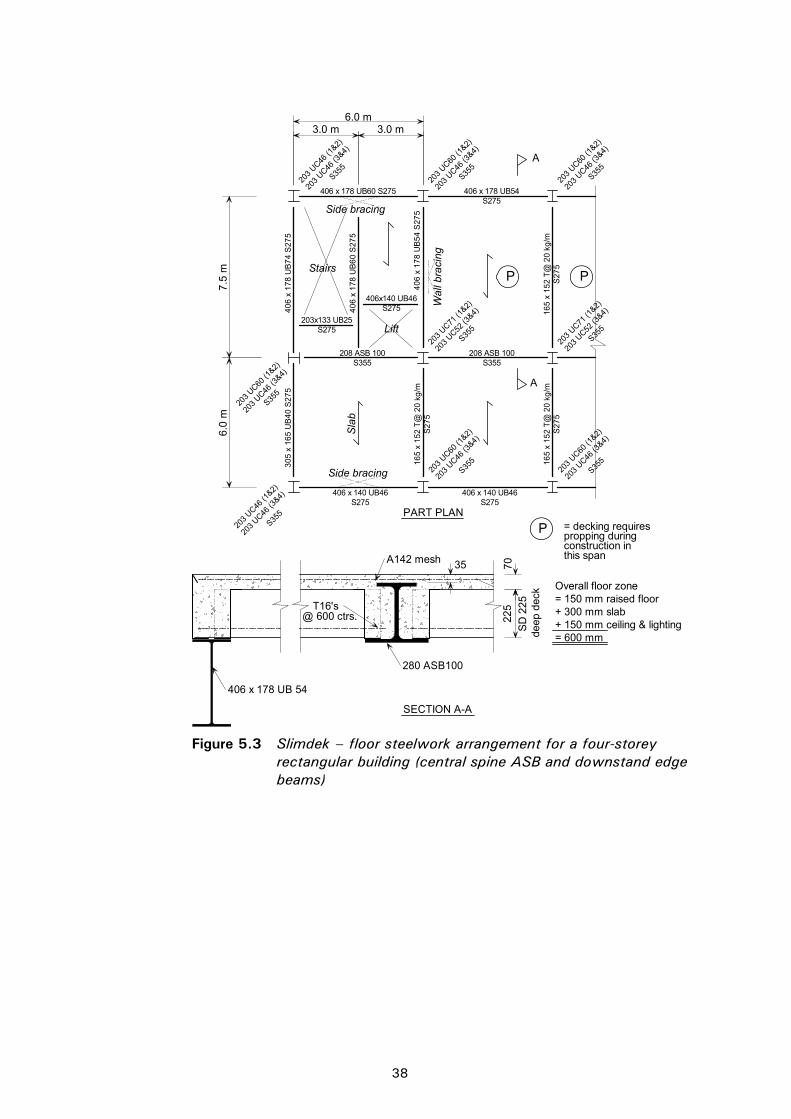
C:\Documents and Settings\faa\My Documents\P365\P365-D09.doc38 Printed 04/11/09
PART PLAN
Side bracing
Wal
l bra
cing
203
UC60 (1
&2)
203
UC46 (1
&2)
203
UC46 (3
&4)
203
UC60 (1
&2)
203
UC60 (1
&2)
203
UC71 (1
&2)
203
UC52 (3
&4)
203
UC46 (3
&4)
203
UC46 (3
&4)
203
UC46 (3
&4)
203
UC46 (3
&4)
203
UC46 (1
&2)
203
UC60 (1
&2)
203
UC46 (3
&4)
203
UC71 (1
&2)
203
UC52 (3
&4)203x133 UB25
S275
Stairs
Side bracing
P
P P
Sla
b
406 x 178 UB60 S275 406 x 178 UB54S275
S355
S355
S355
S355
203
UC60 (1
&2)
203
UC46 (3
&4)
S355
S355
S355
S355
40
6 x
17
8 U
B7
4 S
27
53
05
x 1
65
UB
40
S2
75
40
6 x
17
8 U
B6
0 S
27
5
40
6 x
17
8 U
B5
4 S
27
51
65
x 1
52
T@
20
kg
/mS
27
5
16
5 x
15
2 T
@ 2
0 k
g/m
S2
75
16
5 x
15
2 T
@ 2
0 k
g/m
S2
75
A
A
406 x 140 UB46S275
406 x 140 UB46S275
deep
dec
k
70S
D 2
25 = 150 mm raised floor
+ 150 mm ceiling & lighting+ 300 mm slab
= 600 mm
@ 600 ctrs.
SECTION A-A
208 ASB 100S355
208 ASB 100S355
Lift
406x140 UB46S275
Overall floor zone
= decking requirespropping duringconstruction inthis span
225
S355
6.0 m
6.0
m
3.0 m 3.0 m
A142 mesh
280 ASB100
T16's
406 x 178 UB 54
7.5
m
35
Figure 5.3 Slimdek – floor steelwork arrangement for a four-storey
rectangular building (central spine ASB and downstand edge beams)

C:\Documents and Settings\faa\My Documents\P365\P365-D09.doc39 Printed 04/11/09
Main design considerations
for the floor layout
A central spine of ASBs with decking spanning onto edge beams will generally be more economic than a series of parallel transverse ASBs, for buildings with a rectangular plan shape. Torsion may govern beam design at a change in direction of floor span and for edge beams. RHS Slimflor edge beams designed to resist torsional loading are likely to be the deepest member in a Slimdek floor.
Decking requires propping for spans over 6 m (propped twice at 9 m span).
Slab depth is influenced by the concrete cover to the deck (mainly for fire resistance), cover to the ASB (30 mm minimum, or zero), and cover to the edge beam. ASBs are designed as non-composite if the cover is less than 30 mm.
Detailing of connections around columns should be considered, as the ASB flanges are wider than the column and may need notching.
Advantages Shallow floor zone – reduction in overall building height and cladding. Virtually flat soffit allows easy service installation and offers flexibility of internal wall positions.
Disadvantages Steel weight is often greater than other floor systems.
Connections require careful detailing due to the width of the bottom flange.
Services integration
Virtually flat soffit allows unrestricted access for services below the floor. Small services and ducts (up to 160 mm dia) can be passed through holes in the beam webs and between troughs in the decking.
Governing design criteria
Slab depth may be controlled by fire resistance, ultimate strength or concrete cover to ASB/edge beams.
Deflections, fire resistance, strength or torsional loading governs the size of ASBs.
Design approach 1. Assume beams on a 6 m, 7.5 m or 9 m grid. (Note that decking over 6 m requires propping, which may affect the construction programme.)
2. Choose the decking and design the slab using software. Use lightweight aggregate concrete unless there is a directly-bonded floor covering. Assume LC35/38 concrete, with propping if required. Ensure chosen slab and reinforcement meet the fire resistance required. Note the depth of slab assumed.
3. Design the ASBs using software. Choose fire engineered sections if a solution without fire protection is to be developed. Ensure that the depth of slab is either flush with the top of the ASB (reinforcing bars through the beam web) or is at least 30 mm above the ASB.
4. Design any edge RHS beams using software. Design edge beams as non-composite to avoid the need to install U-bar transverse reinforcement. Design any Universal Beam edge members using resistance tables or software. Ensure the beam depth is compatible with the slab depth, or that it lies within a raised floor.
Typical section sizes
280 ASB 100 for 6 m span at 6 m centres
280 ASB 124 for 7.5 m span at 7.5 m centres
300 ASB 249 for 9 m span at 9 m centres.

C:\Documents and Settings\faa\My Documents\P365\P365-D09.doc40 Printed 04/11/09
Grade of steel ASBs are only available in S355 steel.
RHS Slimflor beams are available in S275 and S355.
Type of concrete
Either normal concrete, 2400 kg/m3, or lightweight aggregate concrete (LWAC), typically density class D1.8 to BS EN 206-1 (1600-1800 kg/m3) can be used.
Normal concrete has better sound reduction, so is better for residential buildings, hospitals, etc.
LWAC is better for overall building weight/foundation design, better span capability of slab, and has better fire insulating properties, enabling slightly thinner slabs (10 mm less) to be used. It is not available in all parts of the UK. LWAC is not considered suitable for directly-bonded floor coverings.
Overall floor zone
Typically, 650 mm with light services (with raised floor).
1000 – 1200 mm with air conditioning (and raised floor).
500 mm (min)
150
400
Raised floor
DuctingFan CoilUnit
LightingCeiling
5050
1000 mm
300
50
Figure 5.4 Slimdek - Typical cross section with air conditioning
150
50
Raised floor
Slimline Fan Coil Unit 200
5050Lighting
Ceiling
800 mm
300Duct through beam
Figure 5.5 Slimdek - Typical cross section without air conditioning

C:\Documents and Settings\faa\My Documents\P365\P365-D09.doc41 Printed 04/11/09
Fire protection Fire engineered ASBs with the web and top flange encased with concrete do not need fire protection for up to 60 minutes.
Thin web ASBs require fire protection for greater than 30 minutes - normally by board.
RHS Slimflor edge beams normally require fire protection for greater than 60 minutes. - normally by board.
Connections ASBs require end plate connections (typically, 6 or 8 bolt) to resist torsional moments. RHS Slimflor beams often use extended end plate connections to minimise the connection width.
Design guidance For details of the Slimdek system, refer to Slimdek manual[20]
For design of ASBs, refer to P175[21]
For the design of RHS Slimflor beams, refer to P169[22]
Software Deep decking/slab: Comdek, from www.corusconstruction.com ASB: design software from www.corusconstruction.com
Edge beams: RHS Slimflor software, from www.corusconstruction.com.

C:\Documents and Settings\faa\My Documents\P365\P365-D09.doc42 Printed 04/11/09
[Blank Page]
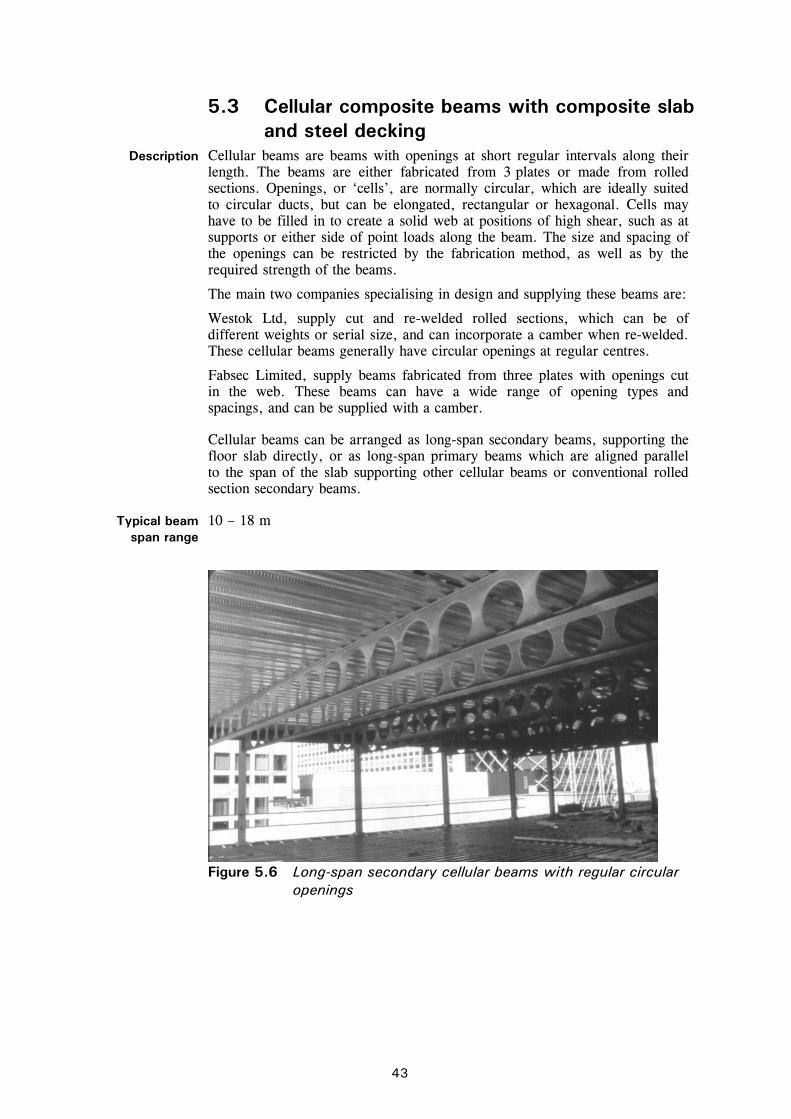
C:\Documents and Settings\faa\My Documents\P365\P365-D09.doc43 Printed 04/11/09
5.3 Cellular composite beams with composite slab and steel decking
Description Cellular beams are beams with openings at short regular intervals along their length. The beams are either fabricated from 3 plates or made from rolled sections. Openings, or ‘cells’, are normally circular, which are ideally suited to circular ducts, but can be elongated, rectangular or hexagonal. Cells may have to be filled in to create a solid web at positions of high shear, such as at supports or either side of point loads along the beam. The size and spacing of the openings can be restricted by the fabrication method, as well as by the required strength of the beams.
The main two companies specialising in design and supplying these beams are:
Westok Ltd, supply cut and re-welded rolled sections, which can be of different weights or serial size, and can incorporate a camber when re-welded. These cellular beams generally have circular openings at regular centres.
Fabsec Limited, supply beams fabricated from three plates with openings cut in the web. These beams can have a wide range of opening types and spacings, and can be supplied with a camber.
Cellular beams can be arranged as long-span secondary beams, supporting the floor slab directly, or as long-span primary beams which are aligned parallel to the span of the slab supporting other cellular beams or conventional rolled section secondary beams.
Typical beam span range
10 – 18 m
Figure 5.6 Long-span secondary cellular beams with regular circular openings

C:\Documents and Settings\faa\My Documents\P365\P365-D09.doc44 Printed 04/11/09
6.
0 m
7.5
m
6.0 m
130
2 No. 19Ø x 100lgstuds @ 300ctrs
3.0 m 3.0 m
660
45
0
Decking1.0 thk
A193 mesh
20
No
. ho
les
@ 6
50
ctrs
.5
75
650
PART PLAN
Side bracing
Wal
l bra
cing
203
UC46 (3
&4)
203
UC46 (3
&4)
203
UC46 (1
&2)
S275
203x133 UB25S275
203x133 UB25S275
Stairs
Side bracing
AA
Slab
203
UC46 (3
&4)
254
UC73 (1
&2)
457 x 152 UB52S275
203
UC60 (1
&2)
203
UC46 (3
&4)
356 x 171 UB51S275
Slab
25
4 x
14
6 U
B3
1 S
27
5
25
4 x
14
6 U
B3
1 S
27
5
457 x 152 UB52S275
254
UC73 (1
&2)
B
B
254
UC73 (1
&2)
203
UC52 (3
&4)20
3 UC46
(1&2)
203
UC46 (3
&4)
254
UC73 (1
&2)
203
UC52 (3
&4)
S355
S355
S355
203
UC60 (1
&2)
203
UC46 (3
&4)
S355
S355
S355
S355
SECTION A-A
45
7 x
19
1 U
B6
7 S
27
5
40
6 x
17
8 U
B6
0 S
27
5
25
4 x
14
6 U
B3
1 S
27
5
356 x 127 UB33 S275
356 x 171 UB45 S275
45
7 x
19
1 U
B7
4 S
27
5 +
45
7 x
19
1 U
B8
2 S
27
5C
ellu
lar
be
am
40
6 x
17
8 U
B6
0 S
27
5
= 150 mm raised floor+ 130 mm slab
+ 660 mm beam+ 150 mm ceiling & lighting
Lift
Overall floor zone
=1090 mm 1100 mm
Figure 5.7 Cellular beams (long-span secondary beams) and composite slabs – example of floor steelwork arrangement for a 4 storey rectangular plan building

C:\Documents and Settings\faa\My Documents\P365\P365-D09.doc45 Printed 04/11/09
Main design considerations
for the floor layout
Secondary beams should be spaced close enough to avoid propping the decking during construction. (3 – 4 m).
Large (elongated or rectangular) openings should be located in areas of low shear, e.g. in the middle third of span for uniformly loaded beams.
Consider integration of the services within the beam depth to minimise the overall floor zone.
Advantages Long, column-free floor spans. Relatively lightweight beams compared with other long-span systems. Economic long-span solution. Precamber can be accommodated during the fabrication of the members.
Disadvantages Increased fabrication costs compared with plain sections.
Services integration
Regular openings in the web allow ducts to pass through the beams. Larger items of equipment are located between the beams. Openings need to allow for any insulation around the services. Ensure web openings align through beams.
Governing design criteria
for beams
Critical check may be elements within the beam – for example, the web posts between openings, particularly near high point loads or adjacent to elongated openings.
The dynamic response of the floor may be critical in some circumstances.
Opening size is ideally within 80% of the finished beam depth, and with a maximum opening length/depth ratio of 2.5. Stiffeners may be required for large openings.
Governing design criteria
for decking/slab
Strength or deflection of the decking in the construction condition.
Fire resistance (affects the concrete cover to the decking and mesh reinforcement size).
Strength or deflection of the slab in the composite condition.
Design approach 1. Assume long-span secondary beams at 3 – 4 m spacing, supported by primary beams on a 6 m, 7.5 m or 9 m column grid
2. Choose the decking and slab, using decking manufacturer’s design tables or software. Use lightweight concrete unless there is a directly-bonded floor covering. Assume LC35/38 concrete, and unpropped decking during construction. Ensure the chosen slab and reinforcement meet the fire resistance required.
3. Design the beams using manufacturer’s software. If stud spacing is not automatic within the software, try shear studs at approximately 300 mm spacing on secondary beams (to suit trough spacing), and at 150 mm spacing on primary beams (The development of moment resistance will often be more severe on a primary beam, demanding closer spacing of studs.) Note that the orientation of the decking will differ between secondary and primary beams. As the services are likely to be integrated, ensure cell sizes and positions are agreed with the services engineer.
Typical section sizes
700 mm deep steelwork for 15 m span at 3.75 m centres.
(Beam + slab depth) span/16-19.
Grade of steel S275 and S355.

C:\Documents and Settings\faa\My Documents\P365\P365-D09.doc46 Printed 04/11/09
LightingCeiling
Raised floor 150
140
10050
Ducting + insulation400 dia.
760
1200
Figure 5.8 Cellular beam - Typical cross section
Type of concrete
Either normal concrete, 2400 kg/m3, or lightweight aggregate concrete (LWAC), typically density class D1,8 to BS EN 206-1 (1600-1800 kg/m3) can be used.
Normal concrete has better sound reduction, so is better for residential buildings, hospitals, etc.
LWAC is better for overall building weight/foundation design, better spancapability of slab, and has better fire insulating properties, enabling slightly thinner slabs (10 mm less) to be used. It is not available in all parts of the UK. LWAC is not considered suitable for directly-bonded floor coverings.
Overall floor zone 1200 mm for 15 m span with 400 mm opening.
Fire protection Intumescent paint, often off-site. Consult fire protection manufacturer; References 23 and 24 give background information on fire protection of beams with web openings.
Connections End plate, in shear only.
Design guidance For choice of decking and composite slab design (including fire resistance); manufacturer’s design tables. For best practice advice in design and construction, refer to P300[17] For design charts and worked example for decking and beams, refer to P055[18] For the basic design of orthodox cellular beams, refer to P100[25]
Software Cellbeam software from www.westok.steel-sci.org Fabsec software from www.fabsec.co.uk
Figure 5.9 Fabricated beam with off-site fire protection

C:\Documents and Settings\faa\My Documents\P365\P365-D09.doc47 Printed 04/11/09
5.4 Slimflor beams with precast concrete slabs Description This is a slim floor system where the beams are contained within the
structural floor depth. A steel plate (typically 15 mm thick) is welded to the underside of a UC section to make the Slimflor beam. This plate extends beyond the bottom flange by 100 mm either side, and supports the precast floor units. A structural concrete topping with reinforcement is recommended to tie the units together. The topping thickness should cover the units by at least 30 mm. If used without a topping (although this is not recommended, because of the difficulty of ensuring adequate dynamic performance), reinforcement should be provided through the web of the beam to tie the floor on each side of the beam together, to meet robustness requirements. Lightweight or normal concrete can be used.
A composite Slimflor beam can be achieved by welding shear connectors (normally 19 mm diameter by 70 mm long) to the top flange of the UC. Reinforcement is then placed across the flange into slots prepared in the precast units, or on top of shallow precast units. If the steel beams are to be designed compositely, the topping should cover the shear connectors by at least 15 mm, and the precast units by 50 mm.
Edge beams are often designed as non-composite, with nominal shear studs provided to meet robustness requirements. These studs are usually site-welded through openings cast in the precast units. Composite edge beams require careful detailing of U-bar reinforcement into slots in the units, and a greater minimum flange width.
Only 152 UCs and 203 UCs are normally suitable as composite beams because the overall depth of the floor slab becomes impractical for larger serial sizes.
Precast units are precambered to cancel out dead load deflections between beams.
Typical beam span range
4.5 m to 7.5 m generally, although 10 m spans can be achieved.
Main design considerations
for the floor layout
Ideally, the span of the precast units and the beam span should be optimised to produce a floor thickness compatible with the Slimflor beam depth. Beams loaded on one side only are relatively heavy because of torsional loading. Torsional loading during construction will need to be checked. A central spine beam with precast units spanning to downstand edge beams will generally be more economic than parallel transverse Slimflor beams. RHS Slimflor edge beams may be used. Composite edge beams require careful detailing of U-bars around the shear connectors and into the precast units or structural topping – non-composite edge beams are usual.
Advantages Beams normally require no fire protection for up to 60 minutes fire protection.
Shallow floor zone – reduction in overall building height and cladding. Virtually flat soffit allows easy service installation and offers flexibility of internal wall positions.
Shear connectors can be welded off site, enabling larger stud diameters to be used and reducing site operations.
Disadvantages The steelwork is relatively heavy.
Extra fabrication is involved in welding the plate to the UC. Connections require more detailing as the plate is wider than the column.
Precast units involve more individual lifting operations than decking, which is delivered and erected in bundles. The erection sequence requires access for installation of the concrete units.
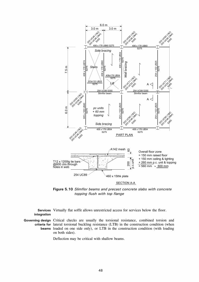
C:\Documents and Settings\faa\My Documents\P365\P365-D09.doc48 Printed 04/11/09
6.0 m
6.0
m7.
5 m
3.0 m 3.0 m
A142 mesh
254 UC89 460 x 15thk plate
T12 x 1200lg tie bars@600 ctrs throughholes in web
SECTION A-A
PART PLAN
= 150 mm raised floor
Side bracingW
all b
raci
ng
203
UC60 (1
&2)
203
UC46 (1
&2)
203
UC46 (3
&4)
203
UC60 (1
&2)
203
UC60 (1
&2)
203
UC71 (1
&2)
203
UC52 (3
&4)
203
UC46 (3
&4)
203
UC46 (3
&4)
203
UC46 (3
&4)
203
UC46 (3
&4)
203
UC46 (1
&2)
203
UC60 (1
&2)
203
UC46 (3
&4)
203
UC71 (1
&2)
203
UC52 (3
&4)203x133 UB25
S275
Stairs
Side bracing
406 x 178 UB60S275
406 x 178 UB60 S275
40
6 x
17
8 U
B7
4S
27
5
40
6 x
17
8 U
B6
0S
27
5 40
6 x
17
8 U
B5
4S
27
5
25
4 x
10
2 U
B2
5S
27
5
S355
S355
S355
S355
S355
S355 A
A
203
UC60 (1
&2)
203
UC46 (3
&4)
S355
30
5 x
16
5 U
B4
0S
27
5
25
4 x
10
2 U
B2
5S
27
5
25
4 x
10
2 U
B2
5S
27
5
S355
S355
406 x 178 UB54S275
406 x 178 UB54S275
254 UC89 S355Slimflor beam
254 UC89 S355Slimflor beam
+ 150 mm ceiling & lighting+ 260 mm p.c. unit & topping
p.c.
unit
Lift
406x178 UB54S275
Overall floor zone
200
60
= 560 mm 600 mm
pc units+ 60 mmtopping
Figure 5.10 Slimflor beams and precast concrete slabs with concrete
topping flush with top flange
Services integration
Virtually flat soffit allows unrestricted access for services below the floor.
Governing design criteria for
beams
Critical checks are usually the torsional resistance, combined torsion and lateral torsional buckling resistance (LTB) in the construction condition (when loaded on one side only), or LTB in the construction condition (with loading on both sides).
Deflection may be critical with shallow beams.

C:\Documents and Settings\faa\My Documents\P365\P365-D09.doc49 Printed 04/11/09
Governing design criteria for
precast units
Bending resistance.
Shear resistance of hollow core units (for high applied shears, or for propped construction, consult plank manufacturer).
The shape/dimensions of the end of the unit (rectangular or chamfered) to allow sufficient gap for free flow of concrete around the steel section (60 mm minimum between the concrete units and the steel is recommended).
Detailing of transverse reinforcement around the beam shear studs and into the precast units, where composite action or improved fire resistance is required.
Length of the unit for end bearing (75 mm minimum for non-composite action and 60 mm minimum for composite action is recommended).
Design approach 1. Try 6 m, 7.5 m or 9 m grid.
2. Choose precast concrete planks from manufacturer’s data. Ensure these meet the required fire resistance. Longer spans are likely to be composite. Note the overall depth.
3. Design the Slimflor beam using software. Beams may be non-composite or composite. Check that the cover to composite beams is at least 15 mm over the studs. If non-composite, allow for ties between the precast units through the web.
4. Design the edge beams – either RHS Slimflor beams loaded on one side or downstand rolled sections. Design the edge beams as non-composite to avoid the need to install u-bar transverse reinforcement.
Typical section sizes
Beam 152 UC 37 + plate for 4.5 m span at 4.5 centres.
Beam 203 UC 71 + plate for 6.0 m span at 6.0 centres.
Beam 254 UC 167 + plate for 7.5 m span at 7.5 centres.
Precast units 150 mm deep for 6 m span, 200 mm deep for 7.5 m span, 260-300 mm deep for 9 m span.
Grade of steel S275 or S355.
Type of concrete Normal concrete, 2400 kg/m3 can be used for the infill around the beams and the topping; concrete with 10 mm maximum aggregate size should be used.
Grade of concrete
Use C20/25 as a minimum, for the infill. Refer to P287[27] and Bison technical information for guidance on the grade of precast concrete.
Overall floor zone
600 mm with small services (with raised floor).
1000 mm with air conditioning (with raised floor).

C:\Documents and Settings\faa\My Documents\P365\P365-D09.doc50 Printed 04/11/09
150 raised floor
250 section
200 section
150 ceiling & lighting
150 ceiling & lighting
500 mm
550 mm
50 concrete topping
85 concrete topping
(a) Non-composite beam with raised floor
(b) Composite beam without raised floor
Slimflor
Slimflor
Figure 5.11 Slimflor construction – typical cross sections
Fire protection The concrete encasement around the beam is normally sufficient for up to
60 minutes fire resistance without additional protection.
For 90 minutes fire protection, an intumescent coating or board protection to the flange plate is required. Correct detailing of transverse reinforcement is required, particularly for hollow core units, where filling of the cores adjacent to the beam is necessary.
Connections Full depth end plate connections are required to resist torsional loading, especially in the construction condition.
Design guidance For the design of slim floor design and construction, P110[26].
For the design of composite Slimflor beams with precast slabs; P287[27].
For the design of RHS Slimflor edge beams; P169[22].
Precast units; manufacturers’ design tables.
Software Slimflor beams: Slimflor software, from www.corusconstruction.com.
Edge beams: RHS Slimflor software, from www.corusconstruction.com.

C:\Documents and Settings\faa\My Documents\P365\P365-D09.doc51 Printed 04/11/09
5.5 Long-span composite beams and composite slabs with metal decking
Description This system consists of composite beams using rolled steel sections supporting a composite slab in a long-span arrangement of, typically, 10 to 15 m. Grids are either arranged with long-span secondary beams at 3 m to 4 m spacing supporting the slab, supported by short-span primary beams, or with short-span secondary beams (6-9 m span) supported by long-span primary beams. The depth of the long-span beams means that service openings, if required, are provided within the web of the beam. Openings can be circular, elongated or rectangular in shape, and can be up to 70% of the beam depth. They can have a length/depth ratio of up to 2.5. Web stiffeners may be required around holes.
Shear studs are normally positioned in pairs, with reinforcing bars placed transversely across the beams to act as longitudinal shear reinforcement.
Typical beam span range
Long-span secondary beams: 9 m to 15 m span at 3 to 4 m spacing.
Long-span primary beams: 9 m to 15 m span at 6 to 9 m spacing.
Main design considerations
for the floor layout
Secondary beams should be placed close enough to avoid propping the decking (3 – 4 m).
Large (elongated or rectangular) openings should be located in areas of low shear, e.g. in middle third of the span for uniformly loaded beams.
Advantages Large column-free areas.
Disadvantages Deeper floor zones.
Heavier steelwork than some short-span solutions.
Fire protection required for 60 minutes fire resistance and above.
Services integration
Service ducts pass through openings in the web of the beams
Larger plant can be situated between beams.
Governing design criteria
for beams
Critical checks are usually deflections and dynamic response. The combined response of primary and secondary beams should be checked. Shear resistance at openings, at supports or at point loads may be critical.
Governing design criteria
for decking/slab
Strength or deflection of the decking in the construction condition.
Fire resistance (affects the concrete cover to the decking and mesh reinforcement size).
Strength or deflection of the slab in the composite condition.

C:\Documents and Settings\faa\My Documents\P365\P365-D09.doc52 Printed 04/11/09
45
0
250
140
6.0
m7.
5 m
6.0 m
533
130
533 x 210 UB92
2 No. 19Ø x 100lgstuds @ 300ctrs
3.0 m 3.0 m
5.0
m6
.75
m8
.5 m
Decking1.0 thk
A193 mesh
PART PLAN
Side bracing
Wal
l bra
cing
203
UC46 (3
&4)
203
UC46 (3
&4)
203
UC46 (1
&2)
S275
203x133 UB25S275
203x133 UB25S275
Stairs
Side bracing
AA
Slab
203
UC46 (3
&4)
254
UC73 (1
&2)
457 x 152 UB52S275
203
UC60 (1
&2)
203
UC46 (3
&4)
356 x 171 UB51S275
Slab
25
4 x
14
6 U
B3
1 S
27
5
25
4 x
14
6 U
B3
1 S
27
5
457 x 152 UB52S275
254
UC73 (1
&2)
B
B
254
UC73 (1
&2)
203
UC52 (3
&4)20
3 UC46
(1&2)
203
UC46 (3
&4)
SECTION A-A
254
UC73 (1
&2)
203
UC52 (3
&4)
Se
ctio
n B
- B
53
3 x
21
0 U
B9
2S
27
5
3 h
ole
s re
qd
S355
S355
S355
203
UC60 (1
&2)
203
UC46 (3
&4)
S355
S355
S355
S355
45
7 x
19
1 U
B6
7 S
27
5
40
6 x
17
8 U
B6
0 S
27
5
25
4 x
14
6 U
B3
1 S
27
5
356 x 127 UB33 S275
40
6 x
17
8 U
B6
0 S
27
5
356 x 171 UB45 S275
= 150 mm raised floor+ 130 mm slab+ 150 mm ceiling & lighting+ 533 mm beam
Lift
Slab
Overall floor zone
= 963 mm 1000 mm
Figure 5.12 Long-span composite beams (with web openings)

C:\Documents and Settings\faa\My Documents\P365\P365-D09.doc53 Printed 04/11/09
Design approach 1. Try long-span secondary beams at 3 – 4 m spacing, on a 6 m, 7.5 m or 9 m column grid
2. Choose the decking and slab, using decking manufacturer’s design tables or software. Use LWAC unless there is a directly-bonded floor covering. Assume LC35/38 concrete, and unpropped decking during construction. Ensure chosen slab and reinforcement meet the fire resistance required.
3. Design beams using software. Try studs at approximately 300 mm spacing on secondary beams (to suit trough spacing), and at 150 mm spacing on primary beams. (The development of moment resistance will often be more severe on a primary beam, demanding closer spacing of studs.) Note that the orientation of the decking will differ between secondary and primary beams. Ensure any holes in the web are of a size and location agreed with the services engineer, and allow for insulation around the services.
Typical section sizes
Composite section depth span/17-20.
533 × 210 × UB 92 for 13.5 m span at 3 m spacing.
Grade of steel S275 or S355.
Type of concrete
Either normal concrete, 2400 kg/m3, or lightweight aggregate concrete (LWAC), typically density class 1,8 to BS EN 206-1 (1600-1800 kg/m3) can be used.
Normal concrete has better sound reduction, so is better for residential buildings, hospitals, etc.
LWAC is better for overall building weight/foundation design, better span capability of slab, and has better fire insulating properties, enabling thinner slabs (10 mm less) to be used. It is not available in all parts of the UK. LWAC is not considered suitable for directly-bonded floor coverings.
Overall floor zone
1000 mm for 13.5 m span (with 250 mm deep web opening)
1200 mm for 15.0 m span (with 400 mm deep web opening)
Fire protection Board, or intumescent coating (often applied off-site).
Connections End plate connections, resisting shear only.
Design guidance For choice of decking and composite slab design (including fire resistance); manufacturer’s design tables.
For best practice advice in composite design and construction; P300[17]
For design charts and worked example for deck and beam; P055[18]
For fire protection; the ‘Yellow Book’[19]
For advice on floor dynamics; P354[6].
Software Slab design: Comdek software, available from www.corusconstruction.com Deckspan software, available from www.rlsd.com Multideck software, available from www. kingspanmetlcon.com/services/software/index.htm Beam design: BDES software, available www.corusconstruction.com

C:\Documents and Settings\faa\My Documents\P365\P365-D09.doc54 Printed 04/11/09
[Blank Page]

C:\Documents and Settings\faa\My Documents\P365\P365-D09.doc55 Printed 04/11/09
5.6 Composite beams with precast units Description This system consists of rolled steel beams with shear studs welded to the top
flange. The beams support precast concrete units with a structural concrete infill over the beam between the ends of the units, and often with an additional topping covering the units. The precast units are either hollow core, normally 150 - 260 mm deep, or they are solid planks of 75 mm to 100 mm depth.
At the supports, the deeper units are either chamfered on their upper face or notched down - to allow a thicker topping depth to fully encase the shear connectors. Narrow slits are created within the units during the manufacturing process to allow transverse reinforcement to be laid across the beams and be embedded in the precast units for approximately 600 mm either side (see Table 5.1 for recommended sizes). For hollow core units, the top of a number of discrete (not adjacent) cores need to be broken out during manufacture so that reinforcement can be placed and concreted into position.
The shear studs and transverse reinforcement allow the transfer of the longitudinal shear force from the steel section into the precast units and the concrete topping, so that they can act together compositely. Composite design is not permitted unless the shear connectors are situated in an end gap (between the concrete units) of at least 50 mm. For on-site welding of shear connectors, a practical minimum end gap between concrete units is 65 mm. Stud capacity depends on the degree of confinement of the stud. Lightweight aggregate concrete or normal concrete may be used for the topping. Hollow cores should be back-filled at the supports for a minimum length equal to the core diameter to provide a solid floor adjacent to the shear connectors, for effective composite action and adequate fire resistance.
Edge beams are often designed as non-composite, with nominal shear studs provided to meet robustness requirements. These studs are usually site-welded through openings cast in the precast units. Composite edge beams require careful detailing of U-bar reinforcement into slots in the units, and a greater minimum flange width.
Minimum flange widths are crucial for providing a safe bearing for the precast units and room for the shear studs – see below for minimum recommended values.
Temporary bracing providing lateral restraint is often required to reduce the effective length for lateral torsional buckling of the beam during the construction stage, when only one side is loaded. Full torsional restraint in the temporary condition may be difficult to achieve, unless deep restraint members with rigid connections are used, or by developing ‘u-frame action’ involving the beams, the restraint members and rigid connections.
Typical beam span range
6 - 9 m span beams, 6 - 9 m span precast units.
Main design considerations
for the floor layout
Maximise the span of the precast units.
A central spine beam with precast units spanning to edge beams will generally be more economic than precast units spanning between parallel transverse beams.
Beams that are parallel to the span of the precast units cannot be designed compositely.
Design edge beams as non-composite, but tied into the floor to meet robustness requirements.
Transverse reinforcement must be provided, as detailed in Table 5.1.
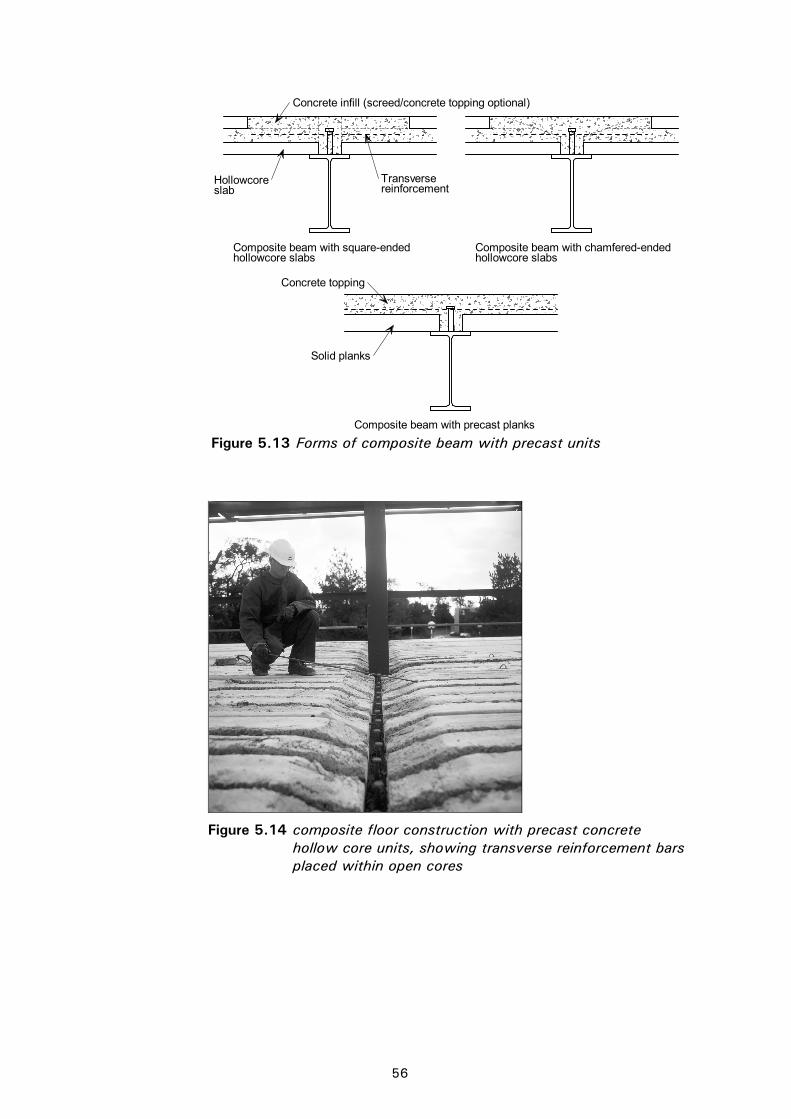
C:\Documents and Settings\faa\My Documents\P365\P365-D09.doc56 Printed 04/11/09
Composite beam with chamfered-endedhollowcore slabs
Composite beam with square-endedhollowcore slabs
Composite beam with precast planks
Concrete infill (screed/concrete topping optional)
Transversereinforcement
Hollowcoreslab
Concrete topping
Solid planks
Figure 5.13 Forms of composite beam with precast units
Figure 5.14 composite floor construction with precast concrete
hollow core units, showing transverse reinforcement bars placed within open cores

C:\Documents and Settings\faa\My Documents\P365\P365-D09.doc57 Printed 04/11/09
Table 5.1 Recommended bar sizes for transverse reinforcement
Slab depth Bar sizes
Solid Planks H10 @ 300 mm centres plus A142 mesh reinforcement
Hollow Core Units (up to 200 mm deep)
H16 @ 200 to 350 mm centres (unless full shear connection is provided, in which case T12 may be used)
Hollow Core Units (up to 260 mm deep)
H16 @ 200 to 350 mm centres
Advantages Fewer secondary beams, due to long-span precast units.
Shear connectors for most beams can be welded off site, enabling larger stud diameters to be used and fewer site operations. It is usually convenient to weld studs to edge beams on site.
Disadvantages The beams are subject to torsion and may need stabilising during the construction stage.
The precast units need careful detailing for adequate concrete encasement of shear connectors and installation of transverse reinforcement.
More individual lifting operations compared to the erection of decking, and the erection sequence requires access for installation of the concrete units.
Services integration
Main service ducts are located below the beams with larger equipment located between beams.
Governing design criteria
for beams
Flange width for bearing and studs, stud size (site-welded or factory-welded)
The critical criteria are often for torsional resistance and twist, or combined torsion and lateral torsional buckling resistance (LTB) in the construction condition (with loading on one side only).
Minimum flange width for bearing:
Internal beam Edge beam
75 or 100 mm deep solid unit 180 mm 210 mm Hollow core unit 180 mm 210 mm Non- composite edge beam 120 mm
Governing design criteria
for precast units
Bending resistance.
Shear resistance of hollow core units.
Detailing of beam transverse reinforcement into units, where composite action or increased fire resistance is required.
Typical section sizes
Beams: Minimum rolled serial size is 406×178 UB for precast units with chamfered end and shop-welded connectors.
Minimum rolled serial size is 457×191 UB for square-ended precast units with shop-welded connectors.
Minimum rolled serial size is 533×210 UB for site-welded shear connectors.
Precast units (approximate):
150 mm deep, 6 m span @ 2.5 kN/m2
200 mm deep, 7.5 m span @ 3.0 kN/m2
250 mm deep, 9 m span @ 5.0 kN/m2

C:\Documents and Settings\faa\My Documents\P365\P365-D09.doc58 Printed 04/11/09
Design approach 1. Try 9 m grid.
2. Choose precast concrete planks from manufacturer’s data. Ensure these meet the required fire resistance. Longer spans are likely to be composite. Note the overall depth.
3. Design the steel beam, using software or P287[27]
4. Design edge beams – as non-composite to avoid costly transverse reinforcement.
Grade of steel S275 or S355
Type of concrete
Either normal concrete, 2400 kg/m3, or lightweight aggregate concrete (LWAC), typically density class D1,8 to BS EN 206-1 (1600-1800 kg/m3) can be used for the infill around the beams and the topping; concrete with 10 mm maximum aggregate size should be used.
Grade of concrete
Use LC25/28 or C25/30 as a minimum.
Overall floor zone 900 mm including ceiling
150 raised floor
200 precast plank
410 beam
800 mm
Figure 5.15 Composite beam and precast concrete unit – typical cross sections
Fire protection Spray, board or intumescent coating to beam.
Transverse bars must be carefully detailed into the precast units – extending 600 mm into each unit. For 90 or 120 minutes fire resistance, a 50 mm (minimum) concrete topping is required.
Connections Full depth end plate connections (welded to the beam flanges) to cater for torsional loading.
For beam design; P287 Design guidance
Precast units; manufacturer’s design tables.
Software Software available from www.bison.co.uk

C:\Documents and Settings\faa\My Documents\P365\P365-D09.doc59 Printed 04/11/09
5.7 Non-composite beams with precast units Description This system consists of rolled steel beams supporting precast concrete units.
The precast units may be supported on the top flange of the steel beams, or, to reduce construction depth, supported on ‘shelf’ angles. Shelf angles are bolted or welded to the beam web, with an outstand leg long enough to provide adequate bearing of the precast units and to aid positioning of the units during erection. Precast concrete units are generally grouted in position. The units may have a screed (which may be structural), or may have a raised floor. The precast units are either hollow core, normally 150-260 mm deep, or they are solid planks of 75 mm to 100 mm depth.
Temporary lateral bracing is often required to limit the effective length for lateral torsional buckling of the beam during the construction stage when only one side is loaded.
In order to meet robustness requirements, mesh and a structural topping may be required, or reinforcement concreted into hollow cores and passed through holes in the steel beam web. Tying may also be required between the concrete units and the edge beams.
Typical beam span range
6 m and 7.5 m grids are common for both beams and precast units.
Main design considerations
for the floor layout
Construction stage loading (planks on one side only) must be considered. Temporary bracing may be required.
Beams loaded on one side only in the permanent condition should either be avoided or designed for the applied torsion.
Central spine beams are common, with smaller edge beams. If edge beams carry significant cladding loads, or support inflexible cladding, deflection may be critical.
Advantages Fewer secondary beams, due to long-span precast units.
A simple solution involving basic member design.
Disadvantages The beams are subject to torsion and may need stabilising during the construction stage.
More individual lifting operations compared with the erection of decking, and the erection sequence requires access for installation of the concrete units.
Services integration
Main service ducts are located below the beams with larger equipment located between beams.
Governing design criteria
for beams
Flange width or shelf angle width for bearing and erection access. A bearing of 75 mm is recommended (50 mm minimum). To allow for tolerances in the precast units and the erected steelwork, a gap of 30 mm between units is usually provided. When the top flange of a beam supports precast planks, the minimum flange width is therefore 178 mm.
Shelf angles should project at least 50 mm beyond the beam flange. When shelf angels are provided, 25 mm clearance is required between the end of the concrete unit and the beam flange, as shown in Figure 5.18.
The critical beam criteria are often torsional resistance and twist, or combined torsion and lateral torsional buckling resistance (LTB) in the construction condition (with loading on one side only).

C:\Documents and Settings\faa\My Documents\P365\P365-D09.doc60 Printed 04/11/09
(a) Units sitting on shelf angles (b) Units sitting on top of downstand beam
Figure 5.16 Floor construction with precast concrete units in non-composite construction
Figure 5.17 Precast concrete units on steelwork

C:\Documents and Settings\faa\My Documents\P365\P365-D09.doc61 Printed 04/11/09
75 min.
25 min.
30 nominal
180 min.
75 min.
50
50 min.
Figure 5.18 Bearing and clearance requirements for precast units
Governing design criteria
for precast units
Bending resistance.
Shear resistance of precast units.
Typical section sizes
Beams: When supporting precast planks on the top flange, the minimum rolled serial size is 406 × 178 UB.
Precast units: (approximate) 150 mm deep, 6 m span @ 2.5 kN/m2
200 mm deep, 7.5 m span @ 3.0 kN/m2
250 mm deep, 9 m span @ 5.0 kN/m2
Design approach 1. Try 6 m or 7.5 m grid.
2. Choose precast concrete planks from manufacturer’s data. Ensure these meet the required fire resistance.
3. Design the steel beams, using software, or by simple manual calculation of the bending moment and deflection, with member resistances taken from the P363[48]
4. Check the temporary construction condition, and consider temporary bracing as part of the erection method.
Grade of steel S275 or S355
Overall floor zone Approximately 800 mm including ceiling (7.5 m grid)

C:\Documents and Settings\faa\My Documents\P365\P365-D09.doc62 Printed 04/11/09
75 75 topping
535 beam
150 ceiling
800 mm(7.5 m grid)
75
50
75
50
200
Figure 5.19 Beam and precast concrete unit – typical cross sections
Fire protection Spray, board or intumescent coating to beam.
For shelf angle beams, 30 or 60 minutes fire resistance may be possible without applied fire protection.
Connections Full depth end plate connections (welded to the beam flanges) are common, as the beams usually carry torsional loading in the construction condition.
For beam design; P364[49] Design guidance
For precast units; manufacturer’s design tables.
Software Beam design – BDES software, available from Corus, can be used to design non-composite beams. BDES is available from www.corusconstruction.com

C:\Documents and Settings\faa\My Documents\P365\P365-D09.doc63 Printed 04/11/09
6 COLUMNS AND CONNECTIONS
6.1 Initial sizing Columns in braced-frame multi-storey buildings are usually hot rolled Universal Column (UC) sections. These sections provide good compression resistance and the connection of beams to the webs and flanges of the columns is straightforward.
Rectangular or circular structural hollow sections are sometimes used, often for aesthetic reasons. Hollow sections can be concrete-filled to achieve higher axial compression resistances and to improve fire resistance.
The column size required will depend on the floor system used, the column spacing and the number of floors. Typical column sizes for column grids appropriate to the use of short-span composite beams with composite slabs are given in Table 6.1. Typically, a single serial size is used over as much of the height as economically feasible, with the actual section size increasing with the number of storeys above the particular location. For ease of construction, columns are usually erected in two-, or sometimes three-, storey sections (i.e. approximately 8 to 12 m lengths).
Table 6.1 Typical column sizes (for column grids up to 6 7.5 m)
Number of floors supported by column section
Universal Column (UC) serial size
1 152
2 – 4 203
3 – 8 254
5 – 12 305
10 – 15 356
For a more project-specific initial choice of column size, the following steps may be used:
1. Determine the design value of axial force in the column, NEd. For initial sizing, consider the design loading on an appropriate area of floor and multiply by the number of floors supported by the column; do not apply the reduction factor given in Section 3.3.2.
2. If the column is an edge column, or has asymmetric loading, increase the design value of axial force to allow for the effect of nominal moments. The more floors the column supports, the smaller the significance of the nominal floor moments. For a column supporting 2 floors, multiply NEd by 1.25; for 4 floors, multiply NEd by 1.15; for 6 floors or more, multiply NEd by 1.05.
3. Using a system length equal to the storey height, select a column section with a design buckling resistance that satisfies 9.0Rdb,Ed NN . Tabulated
values of axial resistance for column sections are given in Reference 48.

C:\Documents and Settings\faa\My Documents\P365\P365-D09.doc64 Printed 04/11/09
6.2 Column design As noted in Section 4, columns in simple construction should be designed for bending moments due to the eccentricity of reactions from the beams, in addition to their axial forces. Figure 6.1 shows the nominal moments that should be considered in simple construction. Beam end reactions should be taken as acting at 100 mm from the face of the steel column. Moments are not introduced into the column when the column is subject to symmetrical reactions and the column is therefore designed for axial force alone. Often, only columns on the edge of the structure will have unbalanced reactions. Most columns within a regular column grid will be designed for axial force only.
The distribution of nominal moments to the upper and lower column sections is carried out in proportion to their stiffness, except where the ratio of the stiffnesses (I/L) does not exceed 1.5, when the moments may be shared equally. Figure 6.2 illustrates the assumed distribution of moments.
To take account of the combined effects of axial forces and bending, NCCI document SN048 (available from www.access-steel.com)[51] offers an expression for the verification of columns in simple construction. A new simplified
100100
R
/2h h
/2w
w
t t
b1,Ed
Rb1,Ed
Mnom = Rb1,Ed(h/2 + 100) Mnom = Rb1,Ed(tw /2 + 100)
Figure 6.1 Nominal moments from floor beams
Upper
Lower
MML u
LL
UU
L
U
/
/
LI
LI
M
M
But
MU = ML
When
5.1/
/
LL
UU LI
LI
Figure 6.2 Distribution of nominal moments from floor beams

C:\Documents and Settings\faa\My Documents\P365\P365-D09.doc65 Printed 04/11/09
interaction criterion which avoids the calculation of ‘k’ factors in Annexes A and B of BS EN 1993-1-1 is given.
For columns in simple construction, the two expressions given in clause 6.3.3(4) of BS EN 1993-1-1, for members in combined bending and axial compression may be replaced by the single expression:
0.15.1Rdcb,z,
Edz,
Rdb,y,
Edy,
Rdb,min,
Ed M
M
M
M
N
N
providing the following criteria are satisfied:
The column is a hot rolled I or H section, or an RHS
The cross section is class 1, 2 or 3 under compression
The bending moment diagrams about each axis are linear
The column is restrained laterally in both the y and z directions at each floor level, but is unrestrained between the floors
Note that Mz,cb,Rd is given by the expression 1M
ypl,y
Wf for class 1 and 2 sections
and M1
yel,y
Wf for class 3 sections. It is important to notice that the partial safety
factor used in this case is M1 and not M0 .
In the case where a column base is nominally pinned, the axial force ratio must also satisfy:
83.0Rdb,y,
Ed N
N
Where Ny,b,Rd is the resistance to buckling about the major axis.
Refer to access steel document SN048 for further information[51].
6.3 Column splices Column splices in braced multi-storey construction are usually provided every two or three storeys. This results in convenient lengths for fabrication, transport and erection, and gives easy access from the adjacent floor for bolting up on site. The provision of splices at each storey level is seldom economical since the saving in column material is generally far outweighed by the material, fabrication and erection costs of making the splice.
6.3.1 Splice position Traditionally, column splices were located about 600 mm above the floor level so that they were at a convenient height for fixing of bolts during erection, and where the internal moments were small. More recent practice is to locate the splice so that edge protection and handrails can be attached at 1100 mm above the floor level, as shown in Figure 6.3.
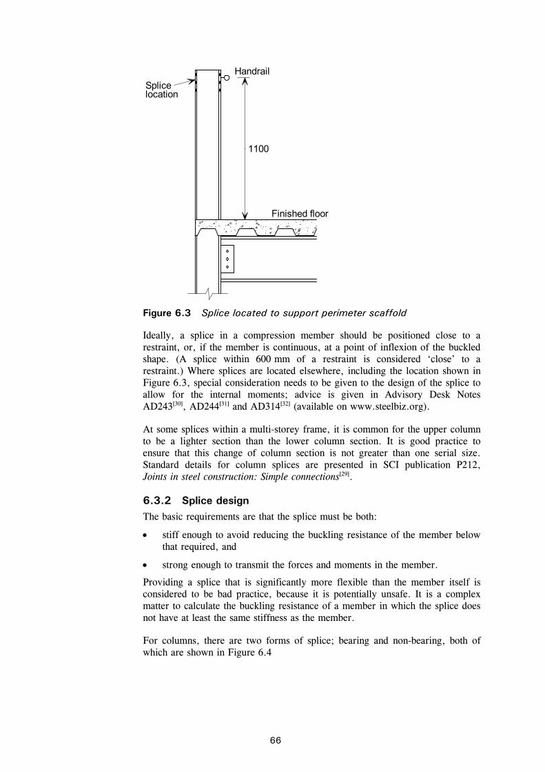
C:\Documents and Settings\faa\My Documents\P365\P365-D09.doc66 Printed 04/11/09
Ideally, a splice in a compression member should be positioned close to a restraint, or, if the member is continuous, at a point of inflexion of the buckled shape. (A splice within 600 mm of a restraint is considered ‘close’ to a restraint.) Where splices are located elsewhere, including the location shown in Figure 6.3, special consideration needs to be given to the design of the splice to allow for the internal moments; advice is given in Advisory Desk Notes AD243[30], AD244[31] and AD314[32] (available on www.steelbiz.org).
At some splices within a multi-storey frame, it is common for the upper column to be a lighter section than the lower column section. It is good practice to ensure that this change of column section is not greater than one serial size. Standard details for column splices are presented in SCI publication P212, Joints in steel construction: Simple connections[29].
6.3.2 Splice design The basic requirements are that the splice must be both:
stiff enough to avoid reducing the buckling resistance of the member below that required, and
strong enough to transmit the forces and moments in the member.
Providing a splice that is significantly more flexible than the member itself is considered to be bad practice, because it is potentially unsafe. It is a complex matter to calculate the buckling resistance of a member in which the splice does not have at least the same stiffness as the member.
For columns, there are two forms of splice; bearing and non-bearing, both of which are shown in Figure 6.4
Handrail
Finished floor
1100
Splicelocation
Figure 6.3 Splice located to support perimeter scaffold

C:\Documents and Settings\faa\My Documents\P365\P365-D09.doc67 Printed 04/11/09
In the bearing type of splice, the axial force is transferred in bearing between the column lengths either directly (same serial size) or via a division plate. The ends of the columns do not need machining – a saw-cut end is satisfactory, and a small gap between bearing surfaces is in fact permitted under the manufacturing tolerances in BS EN 1090-2[33]. Where a division plate is used, assume a spread of force at 45o, as shown in Figure 6.5. The bolts and plates provide continuity of stiffness across the splice, and can be designed to resist a tension force where the rules covering frame robustness are applicable.
In the non-bearing type of splice, all the force is transferred between column lengths by the cover plates, which will generally result in a much larger and more expensive detail. For this reason, the bearing type splice is recommended.
With external cover plates as shown in Figure 6.4, splices can be bulky, and inconvenient and not preferred, for aesthetic reasons. To reduce the overall size, splices are often detailed either with countersunk holes in the splice plates, or using internal cover plates and countersunk holes in the column section, as
Division plate
Air gap
Bearing splice Non-bearing splice (with division plate)
Figure 6.4 Splices in Universal Column Sections
45°
Figure 6.5 Bearing type splice – division plate

C:\Documents and Settings\faa\My Documents\P365\P365-D09.doc68 Printed 04/11/09
shown in Figure 6.6. In this latter detail, the splice can be detailed entirely within the profile of the column section.
Designers should note that if different serial size columns are to be spliced, packs will invariably be required, as shown in Figure 6.7. Depending on the pack thickness and numbers of packs, the shear resistance of the bolts may need to be reduced; designers are referred to Clause 3.6.1 (12) of BS EN 1993-1-8.
For hollow sections, splices are generally achieved with a cap and base plate detail as shown in Figure 6.8.
Countersunk boltsin column flangeinternalcover plate
Countersunk boltsin externalcover plate
Figure 6.6 Compact splice details (both are bearing splices)
Packing
Figure 6.7 Splice connection with packing

C:\Documents and Settings\faa\My Documents\P365\P365-D09.doc69 Printed 04/11/09
Further information on the design of non-bearing and bearing splices to BS EN 1993-1-8, including guidance on initial sizing and worked examples can be found online on the Access Steel web site[51].
6.4 Column bases Base details invariably comprise a square or rectangular plate, welded to the column section. It is recommended that four holding down bolts be provided, outside the section profile. This arrangement of bolts is preferred for three reasons:
The wide spacing of the bolts increases stability in the temporary condition
The bolt arrangement makes plumbing the column simpler
Columns are usually located on a central pack of shims, which can impose a significant point load. If holding down bolts are closely spaced, and in conical sleeves, there may be little remaining concrete. Wider spacing of the bolts leaves an increased block of foundation concrete between the bolts to support the point load.
Despite the four bolt arrangement, details such as those in Figure 6.9 are still considered as nominally pinned when designing the frame.
Figure 6.8 Splice in hollow section column

C:\Documents and Settings\faa\My Documents\P365\P365-D09.doc70 Printed 04/11/09
Full details of standard bases to Universal Column sections and to circular, square and rectangular sections can be found in SCI publication P212[29].
Holding down bolts
Holding down bolts are usually placed in conical sleeves, as shown in Figure 6.9. An anchor plate is generally provided for each bolt, although a common plate or angle section may connect two or more bolts. Holding down bolts should be moved as the concrete cures, to allow lateral movement when the steel is located. If this is not done, the bolts will be held so rigidly that they cannot be inclined to adjust the alignment of the steel base. Bolt holes through the base plate are made 6 mm oversize to allow holding down bolts to be inclined. Best practice is to have all holding down bolts of the same grade, because once the concrete has been cast, errors can be expensive to rectify.
6.5 Bases to braced bays The base detail (and foundation) at the foot of a braced bay is not straightforward, as there will be a high horizontal shear and the possibility of uplift. Depending on the bracing arrangements, these effects may be on different bases, or both applied to the same base in combination.
Ideally, the steel base detail, the foundation and its reinforcement should all be developed together. The following guidance is merely one approach – other solutions are possible.
Non-shrinkcementitiousgrout
Figure 6.9 Typical base detail for Universal Column

C:\Documents and Settings\faa\My Documents\P365\P365-D09.doc71 Printed 04/11/09
Horizontal shear
In combination with axial compression, designers often consider that horizontal shear is carried by friction between the steel and the foundation. For ordinary sand-cement mortar, BS EN 1993-1-8, 6.2.2 gives a coefficient of friction of 0.2, meaning the resistance to horizontal shear is 20% of the vertical compression. This approach is obviously inappropriate in combination with uplift.
Carrying horizontal shear via the holding down bolts is not recommended, as the bolts will experience bending, and thus have a reduced resistance. Designers are referred to Clause 3.6.1 (12) of BS EN 1993-1-8 as an indicator of the reduction in resistance.
When significant horizontal shear must be transferred to the foundations, the column bases are either set in reinforced pockets in the base (see Figure 6.10) and the pockets are subsequently concreted, or a ‘shear key’ can be welded on the underside of the base plate, which locates in a pocket in the foundation, as shown in Figure 6.11
The horizontal shear resistance of the shear nib depends on the the projected area of the nib and on the design strength of the concrete fcd. Guidance on determining the resistance is given in SN021[51] (www.access-steel.com). The stub (and the weld to the column base plate) is designed for horizontal shear alone, assuming no bending occurs.
Figure 6.10 Base located within reinforced pocket
Figure 6.11 Base with shear nib in pocket

C:\Documents and Settings\faa\My Documents\P365\P365-D09.doc72 Printed 04/11/09
Uplift
Ideally, holding down bolts in uplift should be designed at the same time as the reinforced foundation, enabling a properly reinforced solution with the bolts an integral part. Joints in steel construction: Moment connection[34] has a comprehensive approach to calculating the pull-out capacity of a bolt and washer plate assembly. More traditional approaches, based on the pull-out resistance of a cone of concrete, assuming minimum reinforcement in the base, can be found in Holding down systems for steel structures[35] and Steel designer’s manual[36].
6.6 Beam to column connections All the floor systems in Section 5 utilise simple connections – where the connections are assumed to behave as nominal pins, not developing significant moments. To realise this assumption in practice, the connection details must be flexible, to avoid moment transfer, and ductile, in order to accommodate the rotation that develops at the connection. In general, these connection characteristics are realised by detailing the connection with relatively thin connection components that are flexible and accommodate rotation. The industry standard connections are described in Section 6.6.1, and are ‘partial depth’ – the connection detail is approximately 60% of the beam depth.
Full depth connections are provided for floor members that are subject to torsion, such as asymmetric beams or Slimflor beams. For any floor solution, the possibility of torsional loading in the construction stage should be checked, as connections with torsional resistance, or temporary restraints, may be required. In full depth connections, as described in Section 6.6.2, an end plate is welded to the beam flanges in addition to the web. Flexibility and ductility are maintained by using relatively thin end plates.
6.6.1 Simple (shear only) connections When connections are not subject to torsion, nominally pinned connections are usually detailed, providing resistance to vertical shear only. In the UK, three standard beam connections are used, with the choice of detail left to the steelwork contractor. The standard connections are the flexible end plate, a fin plate or double angle cleats, shown in Figure 6.12.
In general, flexible end plates are the most capable when considering vertical shear forces, but less capable than other types of connection if considering
Fin plateFlexible end plate Double angle cleat Figure 6.12 Standard beam connections

C:\Documents and Settings\faa\My Documents\P365\P365-D09.doc73 Printed 04/11/09
substantial tying forces. Each connection type uses standard components. Connections to hollow sections are also straightforward, with the flexible end plate and double angle cleat connections using proprietary ‘blind’ fixings, or bolts using formed, threaded holes. Publication P212[29] gives full details. Although Figure 6.12 shows connections to the flange of a column, the standard details can also be used for connections to column webs. Details of non-standard connections can also be found in P212.
6.6.2 Full depth end plates When connections are subject to torsion, the connection is usually fabricated with a full depth end plate, as shown in Figure 6.13. In these connections, the end plate is welded around the full profile of the member.
It is usual practice for the steelwork contractor to design such connections. The structural designer should provide connection shears and torques for the relevant stages, i.e. during construction and in the final state. This is because for many members, torsion may be a feature at the construction stage, when loading is only applied to one side of the member. Other members, such as RHS Slimflor beams, will be subject to torsion at all stages.
For connections subject to torsion, the welds and the bolt group must be designed for the combined effects of the applied torsion and vertical shear.
When ‘wide’ members, such as ASBs or hollow sections, are connected to the minor axis of a column, a common detail is to weld a plate across the toes of the column flanges, as shown in Figure 6.14. In this situation, the welds between column flanges and the plate need to be designed for the combined effects of vertical shear and any torsion. Similar connection details are often used for RHS Slimflor edge beams, where the RHS is often offset from the centreline of the column to suit the detailing at the perimeter.
ASB end plate details
Figure 6.13 Full depth end plates for ASB and RHS Slimflor beams

C:\Documents and Settings\faa\My Documents\P365\P365-D09.doc74 Printed 04/11/09
6.7 Beam-to-beam connections Beam to beam connections also utilise standard details, although the secondary beam will need to be notched, as shown by a flexible end plate example in Figure 6.15.
Plate weldedacross column toes
Figure 6.14 Typical RHS Slimflor connection to column minor axis
Figure 6.15 Beam to beam connection

C:\Documents and Settings\faa\My Documents\P365\P365-D09.doc75 Printed 04/11/09
7 BRACING MEMBER DESIGN
7.1 General All the members of a bracing system need to be verified for the design forces due to the various combinations of actions. With a triangulated system, it is common to make all diagonal members the same size, adequate to resist the largest design force.
Verify that all columns are tied into all attached beams by a minimum resistance of 1.0% of the column force.
Verify that all the equivalent horizontal forces in the column can be transferred into the relevant bracing system. Diaphragm action in the floor slab may be mobilised to satisfy this condition. These should be designed to resist the sum of the forces mNEd / 100.
7.2 Bracing members and connections Bracing members are often crossed flat steel members (designed in tension) or single hollow section (designed as struts). Other members may include angle sections (usually crossed and designed in tension only), channels or Universal Column sections, if heavily loaded. The local capacity of components within the connection can dominate the design of the member. Careful attention should be paid to how forces are transferred to the bracing member, particularly if this is via thin elements such as webs.
Bracing connections generally involve a gusset plate to which the bracing member is bolted. If bracing is modelled assuming centreline intersection of all members, this presumes that this setting out is rigorously followed in the layout of members as shown in Figure 7.1. However, in practice it is not uncommon to find the actual bracing intersecting with either the beam or column some distance from the connection.
Figure 7.1 Setting out of shallow bracing, with intersecting
centrelines

C:\Documents and Settings\faa\My Documents\P365\P365-D09.doc76 Printed 04/11/09
A common solution is to adjust the setting out point of the bracing, which usually results in a more compact gusset plate supported by both beam and end plate, as shown in Figure 7.2
The setting out shown in Figure 7.2 does mean that additional moments are induced in the column, and this should be allowed for by re-analysing the column with rigid offsets to the bracing nodes.
A careful consideration of load paths through the bracing systems is necessary to determine what proportion of load is transferred to or from the column at each node, and what forces remain within the bracing system. In the bracing systems shown in Figure 7.3, only a small force is transferred horizontally from the floor diaphragm through the column, as most of the horizontal component of the bracing force is internal to the bracing system. The transfer of the vertical component of the bracing force into the column is much more significant, and many more bolts would be expected for this purpose. Note that in the Pratt truss (Figure 7.3), the horizontal beam carries a significant axial force, and would need to be designed for such a force. The forces in the horizontal members of the Warren truss are significantly smaller.
Gusset plates such as that shown in Figure 7.4 are usually designed by considering the capacity of a section of the plate. For simplicity, the horizontal component of force is used to design the horizontal weld, and similarly the vertical component for the vertical weld. More complicated approaches, for example, considering the polar inertia of the weld group, when the line of the axial force is eccentric to the weld’s centre of gravity, are possible, but beyond the scope of this guidance.
Figure 7.2 Alternative setting out of bracing

C:\Documents and Settings\faa\My Documents\P365\P365-D09.doc77 Printed 04/11/09
If gusset plates have to carry a compressive force, the plate should be of a generous thickness. Whilst no definitive rule exists in BS EN 1993-1-8, the thickness of the plate should be such that
tp 30
ew
where:
tp is the plate thickness and
we is as shown in Figure 7.4.
Loads entering bracing systemfrom floor diaphragms
Pratt truss Warren truss Figure 7.3 Bracing systems
30°
W e
Thickness t p
Figure 7.4 Design of gusset plates in tension

C:\Documents and Settings\faa\My Documents\P365\P365-D09.doc78 Printed 04/11/09
The length of unstiffened plate should be minimised. If necessary, some consideration of the buckling capacity of the plate can be made, based on a pin-ended strut with length and breadth as shown in Figure 7.5.
In almost all cases, the addition of gusset plates and the lengthening of the plates will invalidate the assumption that the connection is pinned. Experience has demonstrated however, that structures perform satisfactorily when still based on these simple solutions. If the setting out of the bracing results in significant offset from intersection of centre-lines, this should be taken into account in modelling and in the design moments on the columns.
7.2.1 Flat steel as bracing The critical design criterion will be for tension resistance across the net section, as shown in Figure 7.6.
Note that the net area depends on the hole size deducted (2 mm greater than bolt diameter). BS EN 1993-1-1, 6.2.3 gives the design tension resistance Nt,Rd as the smaller of:
M0
ypl.Rd
AfN and
M2
unetu.Rd
9.0
fAN
eW
L
Figure 7.5 Strut model for gusset plate in compression
Criticalsection
Figure 7.6 Critical check for flat steel bracing

C:\Documents and Settings\faa\My Documents\P365\P365-D09.doc79 Printed 04/11/09
where:
A is the gross area of the cross section
Anet is the net area of the cross sectonn at holes for fastners
fy is the yield strength
fu is the ultimate strength.
The following table gives tensile resistance of typical flat bar bracing, in S275, assuming the bolts are in pairs across the bracing width.
Table 7.1 Typical design values of the tensile resistance of flat bracing
Bolts Flat Resistance (kN) Critical Element
4 M20 150 × 10.0 373 Plate
4 M20 150 × 12.5 376 Bolts
6 M20 200 × 12.5 565 Bolts
4 M24 180 × 15.0 544 Bolts
6 M24 200 × 15.0 781 Plate
6 M24 250 × 15.0 816 Bolts
Note: Resistance values for bolts taken from P363[48]
Due to inevitable imperfections in the erection of a structure, one of the diagonal members in a pair of crossed flat steel braces is often not in tension at all, and tends to buckle laterally. Measures to ensure this does not happen include the deliberate fabrication of the bracing very slightly short, or the inclusion of some detail to adjust the length of the member once erected.
7.2.2 Hollow sections as bracing Hollow sections will invariably be designed as struts, taking an effective length factor of 1.0, as typical gusset plate details are relatively flexible out of plane. The member length is generally calculated from the intersection of column and beam axis. Typical resistances in S355 are given below.
Table 7.2 Typical design values of buckling resistance of circular hollow section bracing
Length (m) Size Resistance (kN) (S355 grade)
114 × 5 270
140 × 5 450
168 ×5 666 4.0
193×8 1,320
114 ×5 99
140 × 5 181
168 ×5 309 7.0
193 ×8 697
Note: resistance values taken from P363[48]
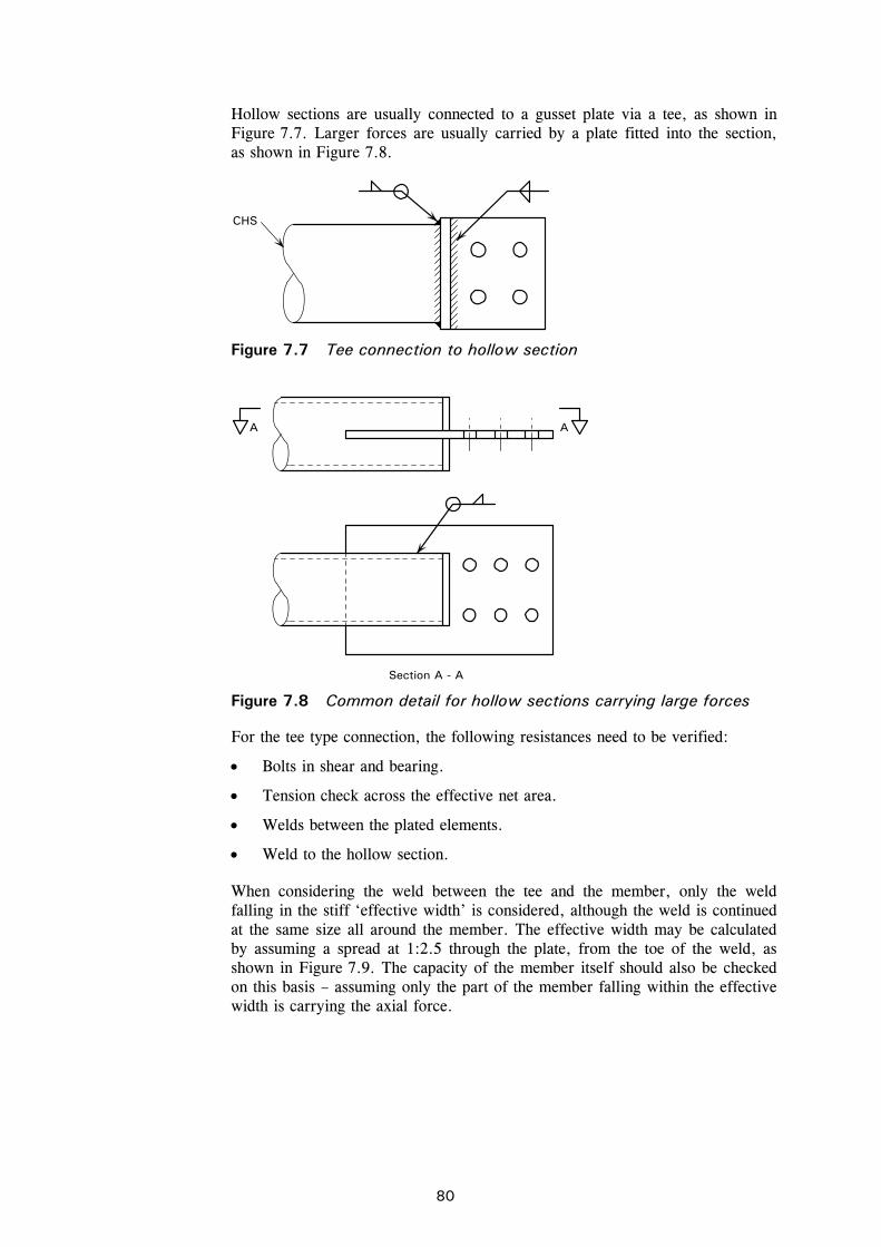
C:\Documents and Settings\faa\My Documents\P365\P365-D09.doc80 Printed 04/11/09
Hollow sections are usually connected to a gusset plate via a tee, as shown in Figure 7.7. Larger forces are usually carried by a plate fitted into the section, as shown in Figure 7.8.
For the tee type connection, the following resistances need to be verified:
Bolts in shear and bearing.
Tension check across the effective net area.
Welds between the plated elements.
Weld to the hollow section.
When considering the weld between the tee and the member, only the weld falling in the stiff ‘effective width’ is considered, although the weld is continued at the same size all around the member. The effective width may be calculated by assuming a spread at 1:2.5 through the plate, from the toe of the weld, as shown in Figure 7.9. The capacity of the member itself should also be checked on this basis – assuming only the part of the member falling within the effective width is carrying the axial force.
CHS
Figure 7.7 Tee connection to hollow section
A A
Section A - A Figure 7.8 Common detail for hollow sections carrying large forces

C:\Documents and Settings\faa\My Documents\P365\P365-D09.doc81 Printed 04/11/09
If the plate is made thick enough to ensure the whole of the hollow section is effective, the weld between the plates (the tee) may also be considered as fully effective. If this is not the case, the weld should be designed on an effective width assuming a 1:2.5 distribution as shown in Figure 7.10
Fillet weld
Effective width
12.5
Figure 7.9 Effective width
Effectivewidth
Effectivewidth
12.5
12.5
Figure 7.10 Distribution of force into tee end connectors
C:\Documents and Settings\faa\My Documents\P365\P365-D09.doc82 Printed 04/11/09
8 ROBUSTNESS
8.1 Accidental design situations As noted in Section 3.1, BS EN 1990 requires that structures be designed for accidental design situations. The situations that need to be considered are set out in BS EN 1991-1-7, and these relate to both identified accidental actions and unidentified accidental actions. The strategy to be adopted in either case depends on three ‘consequence classes’ that are set out in BS EN 1990; for buildings, one of those classes has been subdivided and the categories of building in each class are set out in BS EN 1991-1-7, Table A.1.
For identified accidental actions, design strategies include protecting the structure against the action but, more generally, and for unidentified actions, the structure should be designed to have an appropriate level of ‘robustness’, defined as:
“The ability of a structure to withstand events like fire, explosions, impact or the consequences of human error, without being damaged to an extent disproportionate to the original cause.”
For unidentified actions, the strategy for achieving robustness is set out in BS EN 1991-1-7, 3.3, which says that:
“… the potential failure of the structure arising from an unspecified cause shall be mitigated … by adopting one or more of the following approaches:
a) designing key elements on which the stability of the structure depends, to sustain the effects of a model of accidental action Ad
b) designing the structure so that in the event of a localised failure (e.g. failure of a single member) the stability of the whole structure or of a significant part of it would not be endangered
c) applying prescriptive design/detailing rules that provide acceptable robustness for the structure (e.g. three dimensional tying for additional integrity, or a minimum level of ductility of structural members subject to impact).”
8.2 Consequence classes As mentioned above, BS EN 1990 defines three consequences classes:
CC1 Low consequences of failure
CC2 Medium consequences of failure
CC3 High consequences of failure
Class CC2 is subdivided by BS EN 1991-1-7 into CC2a (Lower risk group) and CC2b (Upper risk group). Medium rise buildings mostly fall within group CC2b. Examples of building categorisation are given in Table 8.1.

C:\Documents and Settings\faa\My Documents\P365\P365-D09.doc83 Printed 04/11/09
Table 8.1 Examples of building categorisation (taken from Table A.1 of BS EN 1991-1-7)
Consequence Class
Example of categorization of building type and occupancy
2b Upper Risk Group
Hotels, flats, apartments and other residential buildings greater than 4 storeys but not exceeding 15 storeys.
Educational buildings greater than single storey but not exceeding 15 storeys.
Retailing premises greater than 3 storeys but not exceeding 15 storeys.
Offices greater than 4 storeys but not exceeding 15 storeys.
All buildings to which the public are admitted and which contain floor areas exceeding 2000 m2 but not exceeding 5000 m2 at each storey.
The recommended strategy for Consequence Class 2b involves either the design for localised failure (see Section 8.3) or the design of columns as key elements (see Section 8.4).
For buildings in the UK, guidance in Approved Document A[38] should be followed (see Section 8.6).
8.3 Design for the consequences of localised failure in multi-storey buildings
8.3.1 Design strategy In multi-storey buildings, the requirement for robustness generally leads to a design strategy where the columns are tied into the rest of the structure. This should mean that any one length of column cannot easily be removed. However, should a length be removed by an accidental action, the floor systems should be able to develop catenary action, to limit the extent of the failure. This can be illustrated diagrammatically, as in Figure 8.1. The recommendations in BS EN 1991-1-7, Annex A in relation to horizontal tying actions and vertical tying actions are related to this form of partial collapse.
Annex A does not prescribe a complete design model for this form of partial collapse – the reaction to the horizontal forces in Figure 8.1 is not addressed, for example. The rules in the Annex are best considered as prescriptive rules intended to produce structures that perform adequately in extreme circumstances, and are not meant to be fully described systems of structural mechanics. The illogical practice of designing certain connections for considerable force, yet not making provision to transfer the forces any further, illustrates this point.
It should be noted that the requirements are not intended to ensure that the structure is still serviceable following some extreme event, but that damage is limited, and that progressive collapse is prevented.
Further general information about robustness can be found in SCI publication P341, Guidance on meeting the robustness requirements in Approved Document A (2004 Edition) [39].

C:\Documents and Settings\faa\My Documents\P365\P365-D09.doc84 Printed 04/11/09
8.3.2 Limit of admissible damage The limit of admissible local damage recommended in BS EN 1991-1-7, Annex A is shown in Figure 8.2. The recommendation is adopted by the UK National Annex. Approved Document A sets a slightly lower limit (damage not exceeding 15% of the floor area or 70 m2, whichever is smaller).
8.3.3 Horizontal tying BS EN 1991-1-7, A.5 provides guidance on the horizontal tying of framed structures. It gives expressions for the design tensile resistance required for internal and perimeter ties.
For internal ties:
LsqgT kki 8.0 or 75 kN, whichever is the greater. (A.1)
For perimeter ties:
LsqgT kkp 4.0 or 75 kN, whichever is the greater. (A.2)
Column removed Figure 8.1 Concept of robustness rules
b)a)
A
BB
Plan Section
Key A) Local damage not exceeding 15 % of the floor area, or 100 m2, whichever is smaller, in each of two adjacent storeys. (B) Notional column to be removed
Figure 8.2 Recommended limit of admissible damage (taken from Figure A.1 of BS EN 1991-1-7)

C:\Documents and Settings\faa\My Documents\P365\P365-D09.doc85 Printed 04/11/09
where:
s is the spacing of ties
L is the span of the tie
is the relevant factor in the expression for combination of action effects for the accidental design situation (i.e. 1 or 2 in accordance with expression (6.11b) of BS EN 1990). See UK NA clause NA.2.2.5 for values to be used.
Note that tying forces do not necessarily need to be carried by the steelwork frame. A composite concrete floor, for example, can be used to tie columns together, but must be designed to perform this function. Additional reinforcement may be required, and the columns (particularly edge columns) may need careful detailing to ensure the tying force is transferred between column and slab. Reinforcing bars around columns, or threaded bars bolted into the steel column itself, have been successfully used.
If the tying forces are to be carried by the structural steelwork alone, note that the check for tying resistance is entirely separate to that for resistance to vertical forces. The shear force and tying forces are never applied at the same time. Furthermore, the usual requirement that members and connections remain serviceable under design loading is ignored when calculating resistance to tying, as ‘substantial permanent deformation of members and their connections is acceptable’. Guidance on the tying capacity of the industry standard connections are presented in P212[29].
Frequently, ties may be discontinuous, or have no ‘anchor’ at the end distant to the column. The connection is simply designed for the applied force. This situation is also common at external columns, where only the local design of the connection is considered. The column itself is not designed to resist the tying force.
8.3.4 Tying of precast concrete floor units BS EN 1991-1-7 clause A.5.1 (2) requires that when concrete or other heavy floor units are used (as floors), they should be tied in the direction of their span. The intention is to prevent floor units or floor slabs simply falling through the steel frame, if the steelwork is moved or removed due to some major trauma. Slabs must be tied to each other over supports, and tied to edge beams. Tying forces may be determined from clause 9.10.2 of BS EN 1992-1-1[40] and its National Annex.
Tying across internal supports
If the precast units have a structural screed, it may be possible to use the reinforcement in the screed to carry the tie forces, as shown in Figure 8.4, or to provide additional reinforcing bars.
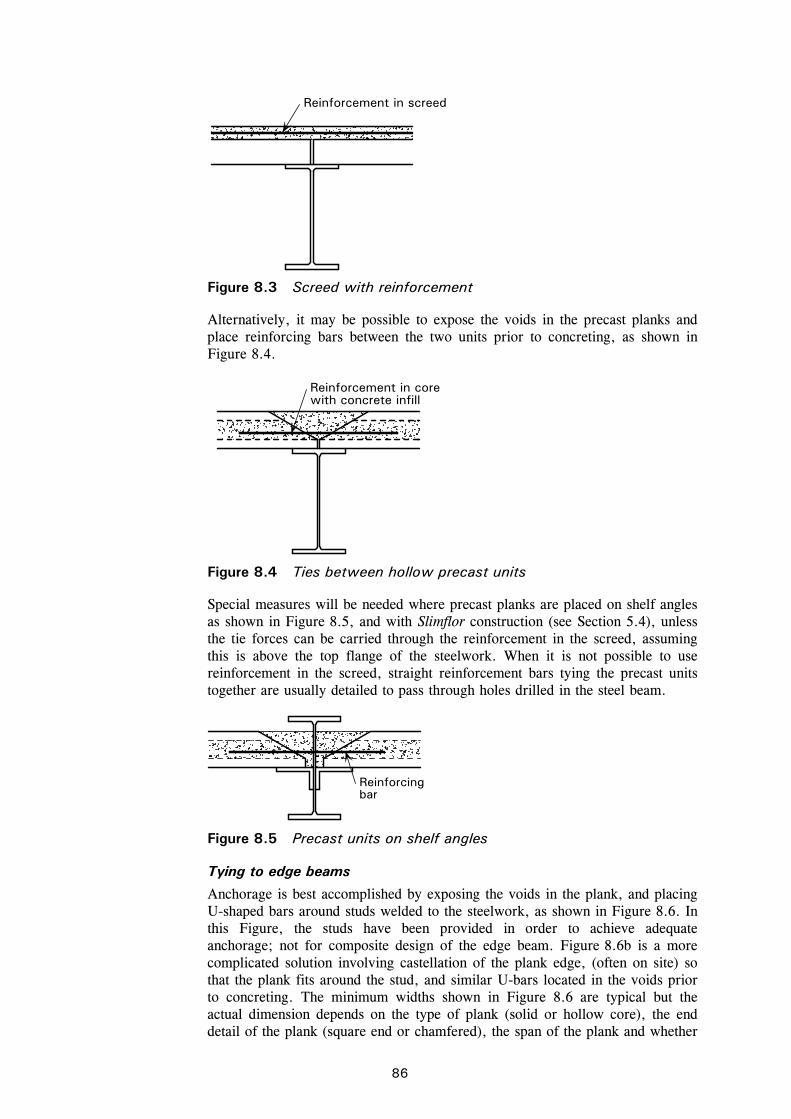
C:\Documents and Settings\faa\My Documents\P365\P365-D09.doc86 Printed 04/11/09
Alternatively, it may be possible to expose the voids in the precast planks and place reinforcing bars between the two units prior to concreting, as shown in Figure 8.4.
Special measures will be needed where precast planks are placed on shelf angles as shown in Figure 8.5, and with Slimflor construction (see Section 5.4), unless the tie forces can be carried through the reinforcement in the screed, assuming this is above the top flange of the steelwork. When it is not possible to use reinforcement in the screed, straight reinforcement bars tying the precast units together are usually detailed to pass through holes drilled in the steel beam.
Tying to edge beams
Anchorage is best accomplished by exposing the voids in the plank, and placing U-shaped bars around studs welded to the steelwork, as shown in Figure 8.6. In this Figure, the studs have been provided in order to achieve adequate anchorage; not for composite design of the edge beam. Figure 8.6b is a more complicated solution involving castellation of the plank edge, (often on site) so that the plank fits around the stud, and similar U-bars located in the voids prior to concreting. The minimum widths shown in Figure 8.6 are typical but the actual dimension depends on the type of plank (solid or hollow core), the end detail of the plank (square end or chamfered), the span of the plank and whether
Reinforcement in screed
Figure 8.3 Screed with reinforcement
Reinforcement in corewith concrete infill
Figure 8.4 Ties between hollow precast units
Reinforcingbar
Figure 8.5 Precast units on shelf angles

C:\Documents and Settings\faa\My Documents\P365\P365-D09.doc87 Printed 04/11/09
the studs on the beam have been shop or site welded. Guidance on the minimum dimensions for the varying situations is given in Reference 27.
It should be noted that loading a beam on one side only produces significant torque in the beam itself, which may well be the critical design case. The eccentricity must be accounted for in design of the member, connections and columns.
In some circumstances, the floor units cantilever past the edge beam. Tying in these situations is not straightforward, and a solution must be developed in collaboration with the frame supplier and floor unit manufacturer.
8.3.5 Vertical tying BS EN 1991-1-7, A.6 provides guidance on the vertical tying of framed structures. It recommends that column splices should be capable of carrying an axial tension equal to the largest design vertical permanent and variable load reaction applied to the column from any one storey. (It does not specify which storey but it would be appropriate to use the largest value over the length down to the next splice, or to the base, if that is nearer.)
In practice, this is not an onerous obligation, and most splices designed for adequate stiffness and robustness during erection are likely to be sufficient to carry the axial tying force. SCI publication P212[29] has details of standard splices, and gives guidance on determining axial tension capacities to simplify the design checks.
8.4 Key elements BS EN 1991-1-7, A.8 provides guidance on the design of ‘Key elements’. It recommends that a key element should be capable of sustaining an accidental design action of Ad applied in horizontal and vertical directions (in one direction at a time) to the member and any attached components. The recommended value of Ad for building structures is 34 kN/m2. Any other structural component that provides ‘lateral restraint vital to the stability’ of a key element should also be designed as a key element. See comment on accidental design combinations in Section 3.2.1.
When considering the accidental loading on a large area (e.g. on a floor slab supported by a transfer beam), it is reasonable to limit the area that is subjected to the 34 kN/m2 load because a blast pressure is unlikely to be this high on all the surfaces of a large enclosed space. The maximum area is not defined but could be inferred from the length of load-bearing wall to be considered
U-bar U-bar
a)
Minimum flangewidth = 120 mm
b)
Minimum flangewidth = 180 mm
Plank castellatedaround shear studs
Figure 8.6 Tying of precast planks to edge beams

C:\Documents and Settings\faa\My Documents\P365\P365-D09.doc88 Printed 04/11/09
(see BS EN 1991-1-7, A.7), which is 2.25 times the storey height, say 2.25 2.9 = 6.5 m. Therefore, a maximum area that would be subjected to the 34 kN/m2 could be a 6.5 × 6.5 m square.
For the design of a key element, it is necessary to consider what components, or proportion of components, will remain attached to the element in the event of an incident. The application of engineering judgement will play a major part in this process. For framed construction, the walls and cladding will normally be non-structural. Therefore, it is likely that the majority of these will become detached from the key element during an incident, as shown in Figure 8.7. For the column member key element shown in Figure 8.7, an accidental load of 34 kN/m2 should be applied over a width beff for accidental loading about the major axis. The column section should be checked for the combination of moments and axial force using the design case given above. The accidental loading about the minor axis over a width of h (in this case) also needs to be considered. The accidental loading should only be considered as acting in one direction at a time and there is no requirement to consider a diagonal loading case i.e. at an angle to the major and minor axes.
Determining the width beff is very subjective. An estimation of what will remain attached to the key element (during a loading of 34 kN/m2) will obviously depend on what is attached and how it is fixed to the element.
8.5 Risk assessment Buildings which fall into consequence class 3 have to be assessed using risk assessment techniques. Annex B of BS EN 1991-1-7 provides information on risk assessment and B.9 provides guidance specific to buildings. Guidance on risk assessment is given in Section 6.2 of SCI Publication P341[39]
b
h
eff
Key elementPart of componentthat remains attachedto key elementafter an incident
Part of componentthat is detached from key elementduring an incident
Plan view Figure 8.7 Component attached to a key element (column)

C:\Documents and Settings\faa\My Documents\P365\P365-D09.doc89 Printed 04/11/09
8.6 The Building Regulations Part A and Approved Document A
In England and Wales The Building Regulations[37], together with Approved Document A[38], include requirements for the avoidance of disproportionate collapse. In the Regulations, Requirement A3 states:
“Disproportionate Collapse A3. The building shall be constructed so that in the event of an accident the building will not suffer collapse to an extent disproportionate to the cause.”
Requirement A3 is applicable to all buildings.
Approved Document A gives guidance on how requirement A3 should be applied to different types and sizes of building.
In Scotland and in Northern Ireland, there are equivalent regulations for preventing disproportionate collapse that require the designer to consider the extent of damage caused by accidental actions.
The recommendations in Section 5 of Approved Document A effectively mirror those in Annex A of BS EN 1991-1-7.

C:\Documents and Settings\faa\My Documents\P365\P365-D09.doc90 Printed 04/11/09
9 REQUIREMENTS FOR FIRE RESISTANCE
9.1 General The fundamental concern for the structural designer when considering fire, is to design the structure such that its stability will be maintained for a reasonable period. This functional requirement is described in the Building Regulations. Ensuring the structural elements have a certain period of fire resistance (usually 30, 60 or 90 minutes) will generally be taken as evidence that the functional requirements for building stability in the event of a fire will be met. In England and Wales, appropriate periods of fire resistance are given in Approved Document B[41]. In Scotland, they are given in Part D of Technical standards for compliance with the Building Standards[42]. In Northern Ireland, they are given in Technical Booklet E[43]. The appropriate periods of fire resistance for elements of structure depend on building type and height. The period of fire resistance is important, as the basic structure may be affected by the approach chosen to achieve the required resistance.
9.1.1 Periods of fire resistance The minimum periods of fire resistance for buildings in England and Wales as set out in Appendix A, Table A2 of Approved Document B, depending on occupancy and building height are summarised below for multi-storey buildings in Table 9.1. Definitions of height measurements are given in Figure 9.1.
Table 9.1 Minimum periods (minutes) of fire resistance for elements of structure (based on Approved Document B, Table A2)
Basement storey including floor over
Ground or upper storey
Depth (m) of lowest basement
Height (m) of top floor above ground in building or separated part of building
Purpose of building
10 < 10 5 18 30 > 30
Residential: flats and maisonettes
90 60 30 60 90 120
Office: Not sprinklered 90 60 30 60 90 NA
Office: Sprinklered 90 60 30 30 60 120
Note: Further categories of buildings are given in Approved Document B.
9.1.2 Fire performance of structural elements The fire resistance of an element of structure is judged against 3 criteria:
Load-bearing capacity, (R)
Integrity, (E)
Insulation, (I)
Load bearing capacity is the ability of an element (beam, column, floor etc.) to resist collapse and maintain structural stability.
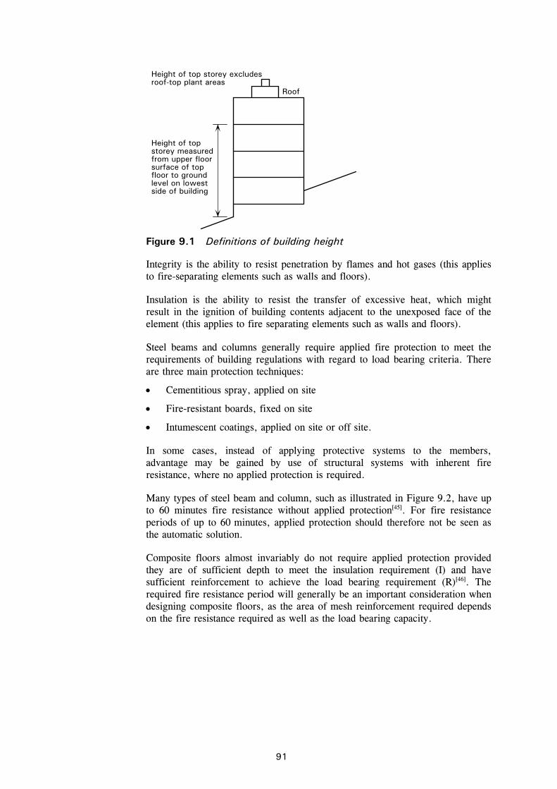
C:\Documents and Settings\faa\My Documents\P365\P365-D09.doc91 Printed 04/11/09
Integrity is the ability to resist penetration by flames and hot gases (this applies to fire-separating elements such as walls and floors).
Insulation is the ability to resist the transfer of excessive heat, which might result in the ignition of building contents adjacent to the unexposed face of the element (this applies to fire separating elements such as walls and floors).
Steel beams and columns generally require applied fire protection to meet the requirements of building regulations with regard to load bearing criteria. There are three main protection techniques:
Cementitious spray, applied on site
Fire-resistant boards, fixed on site
Intumescent coatings, applied on site or off site.
In some cases, instead of applying protective systems to the members, advantage may be gained by use of structural systems with inherent fire resistance, where no applied protection is required.
Many types of steel beam and column, such as illustrated in Figure 9.2, have up to 60 minutes fire resistance without applied protection[45]. For fire resistance periods of up to 60 minutes, applied protection should therefore not be seen as the automatic solution.
Composite floors almost invariably do not require applied protection provided they are of sufficient depth to meet the insulation requirement (I) and have sufficient reinforcement to achieve the load bearing requirement (R)[46]. The required fire resistance period will generally be an important consideration when designing composite floors, as the area of mesh reinforcement required depends on the fire resistance required as well as the load bearing capacity.
Roof
Height of topstorey measured from upper floorsurface of topfloor to groundlevel on lowestside of building
Height of top storey excludesroof-top plant areas
Figure 9.1 Definitions of building height
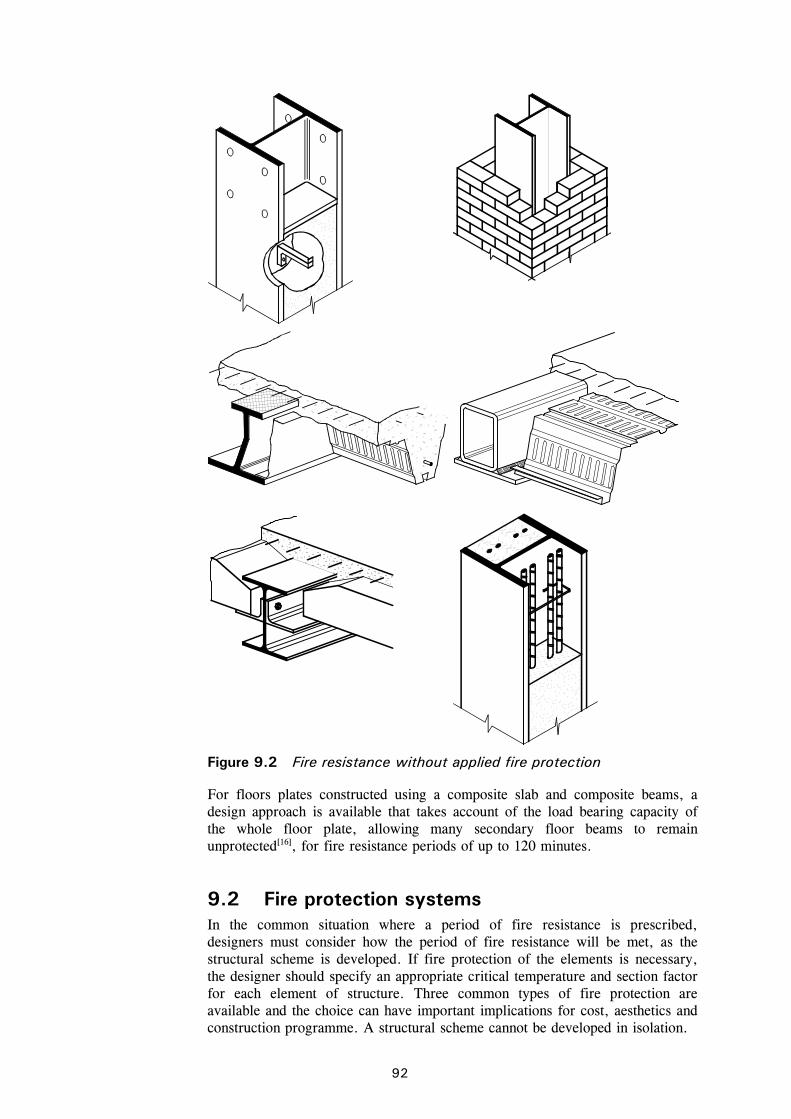
C:\Documents and Settings\faa\My Documents\P365\P365-D09.doc92 Printed 04/11/09
For floors plates constructed using a composite slab and composite beams, a design approach is available that takes account of the load bearing capacity of the whole floor plate, allowing many secondary floor beams to remain unprotected[16], for fire resistance periods of up to 120 minutes.
9.2 Fire protection systems In the common situation where a period of fire resistance is prescribed, designers must consider how the period of fire resistance will be met, as the structural scheme is developed. If fire protection of the elements is necessary, the designer should specify an appropriate critical temperature and section factor for each element of structure. Three common types of fire protection are available and the choice can have important implications for cost, aesthetics and construction programme. A structural scheme cannot be developed in isolation.
Figure 9.2 Fire resistance without applied fire protection
C:\Documents and Settings\faa\My Documents\P365\P365-D09.doc93 Printed 04/11/09
Sprayed cementitious or gypsum based coatings
These relatively cheap forms of fire protection are usually applied on site, are excellent at coating complex fabrications, but have the disadvantages of a ‘wet’ trade on site. The application tends to be messy, and usually requires other trades to be excluded. Sprayed cementitious materials are vulnerable to mechanical damage.
Boards and Blankets
Boards are made from a variety of materials, with different finishes. Columns and regular beams are often protected with boards. Blankets may be used around such items as trusses, where boards would be inefficient.
Intumescent coatings
Most intumescent coatings in common use are ‘thin film’, which swell and char on exposure to fire, protecting the steel. Intumescent coatings may be applied on site, but are often applied off-site[44], and consequently are off the critical site construction programme. Complex fabrications such as cellular beams or plate girders are usually protected with intumescent coating.
9.3 Sources of further advice The following resources are recommended further reading:
Structural fire safety: A handbook for architects and engineers[7]
This publication presents a useful overview of the subject, without detailed design guidance.
Design of steel-framed buildings without applied fire protection[45] This publication describes the ways in which up to 60 minutes fire resistance can be achieved without protection. The publication also contains worked example calculations of the fire engineering design of:
A Slimflor beam
An ASB
A beam with shelf angles
A partially encased beam
A partially encased column
A concrete filled structural hollow section
A shallow composite slab
A deep composite slab.
Fire safe design – A new approach to multi-storey steel-framed buildings[16] This publication describes the design approach for structures with composite floors and a required fire resistance period of up to 60 minutes. By following the guidance, many floor beams can be left unprotected, offering considerable advantage.
Steel building design: Fire resistant design[50] This publication provides a general overview of the rules for structural fire design of steel and composite buildings in accordance with the Eurocodes.

C:\Documents and Settings\faa\My Documents\P365\P365-D09.doc94 Printed 04/11/09
10 REFERENCES
10.1 General references 1. BRITISH COUNCIL FOR OFFICES
BCO Guide 2005 Best practice in the specification for offices BCO, 2005 (available from http://www.bco-officefocus.com)
2. CIMSTEEL Design for construction (P178) The Steel Construction Institute, 1997
3. Code of Practice for metal decking and stud welding (37/04) The British Constructional Steelwork Association, 2004
4. McKENNA, P. D. and LAWSON, R. M. Interfaces: Design of steel-framed buildings for service integration (P166) The Steel Construction Institute, 1997
5. MITCHELL, S., HEYWOOD, M. and HAWKINS, G. Service co-ordination with structural beams. Guidance for a defect-free interface (IPE2) The Steel Construction Institute and BSRIA, 2004
6. SMITH, A. L., HICKS, S. J. and DEVINE, P. J. Design of floors for vibration: A new approach (P354) The Steel Construction Institute, 2007
7. HAM, S. J., NEWMAN, G. M., SMITH, C. I. and NEWMAN, L. C. Structural fire safety: A handbook for architects and engineers (P197) The Steel Construction Institute, 1999
8. Building Regulations 2000. Approved Document E: Resistance to the passage of sound (2003 ed) E1: Protection against sound from other parts of the building and adjoining buildings E2: Protection against sound within a dwelling-house etc. The Stationery Office, 2006
9. BS 8233:1999 Sound insulation and noise reduction for buildings. Code of Practice British Standards Institution, 1999
10. GORGOLEWSKI, M. T. and LAWSON, R. M. Acoustic performance of Slimdek (P321) The Steel Construction Institute 2003
11. GORGOLEWSKI, M. T. and LAWSON, R. M. Acoustic performance of composite floors (P322) The Steel Construction Institute, 2003
12. GORGOLEWSKI, M. T. and LAWSON, R. M. Acoustic performance of light steel-framed systems (P320) The Steel Construction Institute, 2003
13. WAY, A. G. J. and COUCHMAN, G. H. Acoustic detailing for steel construction (P372) The Steel Construction Institute, 2008

C:\Documents and Settings\faa\My Documents\P365\P365-D09.doc95 Printed 04/11/09
14. Building Regulations 2000 - Approved Document L2A Conservation of fuel and power. L2A Conservation of fuel and power in new buildings other than dwellings (2006 edition) The Stationery Office, 2006
15. Information about Corefast is available from the Corus web site: www.corusconstruction.com/en/reference/publications/structural_steel/corefast
16. NEWMAN, G. M., ROBINSON, J. T. and BAILEY, C. G. Fire safe design: A new approach to multi-storey steel-framed buildings. Second Edition (P288) The Steel Construction Institute, 2006
17. COUCHMAN, HICKS, S. J. and RACKHAM, J. W. Composite slabs and beams using steel decking: Best practice for design and construction (Second Edition) (P300) The Steel Construction Institute, 2009
18. LAWSON, R. M. Design of composite slabs and beams with steel decking (P055) The Steel Construction Institute, 1989
19. ASSOCIATION FOR SPECIALIST FIRE PROTECTION and THE STEEL CONSTRUCTION INSTITUTE Fire protection for structural steel in buildings. Fourth edition (Available only as a pdf from www.asfp.org.uk) ASFP/ SCI/ FTSG, 2007
20. CORUS Slimdek Manual Corus, 2001
21. LAWSON, R. M., MULLETT, D. L. and RACKHAM, J. W. Design of asymmetric Slimflor beams using deep composite decking (P175) The Steel Construction Institute, 1997
22. MULLETT, D. L. Design of RHS Slimflor edge beams (P169) The Steel Construction Institute, 1997
23. AD 319: Update on the fire protection of beams with web openings Advisory Desk in New Steel Construction, vol 16(4) 2008
24. SIMMS, W. I. RT1187 Guidance on the fire protection of beams with web openings, The Steel Construction Institute, 2008
25. WARD, J. K. Design of composite and non-composite cellular beams (P100) The Steel Construction Institute, 1994
26. MULLETT, D. M. Slim floor design and construction (P110) The Steel Construction Institute, 1992
27. HICKS, S. J. and LAWSON, R. M. Design of composite beams using precast concrete slabs (P287) The Steel Construction Institute, 2003
28. BROWN, D. G., KING, C. M., RACKHAM, J. W. and WAY, A. Design of multi-storey braced frames (P334) The Steel Construction Institute, 2004

C:\Documents and Settings\faa\My Documents\P365\P365-D09.doc96 Printed 04/11/09
29. Joints in steel construction: Simple connections (P212) The Steel Construction Institute and The British Constructional Steelwork Association, 2002
30. AD 243: Splices within unrestrained lengths Advisory Desk in New Steel Construction, vol 8(6), 2000
31. AD 244: Second order moments Advisory Desk in New Steel Construction, vol 8(6), 2000
32. AD 314: Column splices and internal moments Advisory Desk in New Steel Construction, vol 15(8), 2007
33. BS EN 1090-2, Execution of steel structures and aluminium structures Part 2: Technical requirements for steel structures BSI, 2008)
34. Joints in steel construction: Moment connections (P207) The Steel Construction Institute and The British Constructional Steelwork Association, 1995
35. Holding down systems for steel stanchions Constrado, BCSA and Concrete Society, 1980
36. DAVISON, B. and OWENS, G. W. (Editors) Steel designers’ manual (6th edition) Blackwell Publishing, 2003
37. Building Regulations 2000 (SI 2000/2531) As amended by: The Building (Amendment) Regulations 2001 (SI 2001/3335), The Building (Amendment) Regulations 2002 (SI 2002/440) The Building (Amendment) (No. 2) Regulations 2002 (SI 2002/2871) The Building (Amendment) Regulations 2003 (SI 2003/2692) The Building (Amendment) Regulations 2004 (SI 2004/1465)) The Stationery Office
38. Building Regulations 2000 – Approved Document A (2004 Edition) Structure Approved Document A – Amendments 2004 The Stationery Office
39. WAY, A. G. J. Guidance on meeting the robustness requirements in Approved Document A (2004 Edition) (P341) The Steel Construction Institute, 2005
40. BS EN 1992 Eurocode 2: Design of concrete structures BS EN 1992-1-1: General rules and rules for buildings BSI, 2004
41. Building Regulations 1991 - Approved Document B – Fire Safety (includes 1992 amendments - now superseded by 2000 edition) See also: Amendments 2002 to Approved Document B (Published by ODPM) The Stationery Office
42. The Building Standards Amendment (Scotland) Regulations 2001 Technical Document D, Structural Fire Precautions Scottish Executive, 2002

C:\Documents and Settings\faa\My Documents\P365\P365-D09.doc97 Printed 04/11/09
43. The Building Regulations (Northern Ireland) Technical Booklet E Fire Safety (as amended 2000) The Stationery Office, Belfast
44. NEWMAN, L.C., DOWLING, J. J. and SIMMS, W. I. Structural fire design: Off-site applied thin film intumescent coatings, Second edition (P160) The Steel Construction Institute, 2005
45. BAILEY, C. G., NEWMAN, G. M. and SIMMS, W. I. Design of steel-framed buildings without applied fire protection (P186) The Steel Construction Institute, 1999
46. NEWMAN, G. M. The fire resistance of composite floors with steel decking. Second edition (P056) The Steel Construction Institute, 1991
47. Steel building design: Introduction to the Eurocodes (P361) The Steel Construction Institute, 2009
48. Steel building design: Design data (P363) The Steel Construction Institute and The British Constructional Steelwork Association, 2009
49. Steel building design: Worked examples – open sections (P364) The Steel Construction Institute, 2009
50. Steel building design: Fire resistant design (P375) The Steel Construction Institute, 2009
51. Access Steel www.access-steel.com
52. GULVANESSIAN, H., CALGARO, J-A, and HOLICKÝ, M. Designers’ Guides to EN 1990; Eurocode: Basis of structural design, Thomas Telford, 2002
C:\Documents and Settings\faa\My Documents\P365\P365-D09.doc98 Printed 04/11/09
11 BIBLIOGRAPHY
11.1 References to the Structural Eurocodes The Eurocodes have been produced as harmonised documents by CEN and numbered as ‘EN’ documents, such as EN 1990. Each Part is published by the appropriate national standards body under a cover that adds the national standards prefix to the designation (e.g. ‘BS’ in the UK). Each Part may be accompanied by a National Annex, either together with the CEN text or separately.
Various Eurocode Parts are referred to in the text of this publication with a the BS prefix, e.g. BS EN 1991. The following Parts are relevant to steel and composite buildings:
BS EN 1990 Eurocode Basis of structural design
BS EN 1991 Eurocode 1: Actions on structures
BS EN 1991-1-1 Part 1-1: General actions. Densities, self-weight, imposed loads for buildings
BS EN 1991-1-2 Part 1-2: General actions. Actions on structures exposed to fire
BS EN 1991-1-3 Part 1-3: General actions. Snow loads
BS EN 1991-1-4 Part 1-4: General actions. Wind actions
BS EN 1991-1-5 Part 1-5: General actions. Thermal actions
BS EN 1991-1-6 Part 1-6: General actions. Actions during execution
BS EN 1991-1-7 Part 1-7: General actions. Accidental actions
BS EN 1992 Eurocode 2: Design of concrete structures
BS EN 1992-1-1 Part 1-1: General rules and rule for buildings
BS EN 1992-1-2 Part 1-2: General rules – Structural fire design
BS EN 1993 Eurocode 3: Design of steel structures
BS EN 1993-1-1 Part 1-1: General rules and rules for buildings
BS EN 1993-1-2 Part 1-2: General rules – Structural fire design
BS EN 1993-1-3 Part 1-3: General rules – Supplementary rules for cold-formed members and sheeting
BS EN 1993-1-5 Part 1-5: Plated structural elements
BS EN 1993-1-8 Part 1-8: Design of joints
BS EN 1993-1-9 Part 1-9: Fatigue
BS EN 1993-1-10 Part 1-10: Material toughness and through-thickness properties
BS EN 1993-1-12 Part 1-12: Additional rules for the extension of EN 1993 up to steel grades S700

C:\Documents and Settings\faa\My Documents\P365\P365-D09.doc99 Printed 04/11/09
BS EN 1994 Eurocode 4: Design of composite steel and concrete structures
BS EN 1994-1-1 Part 1-1: General rules and rules for buildings
BS EN 1994-1-2 Part 1-2: General rules – Structural fire design
All of these Parts and the corresponding UK National Annexes have been published by BSI.
11.2 Guidance on design to the Eurocodes The publications listed below are in accordance with Eurocodes and the UK National Annexes
1. Steel building design: Introduction to the Eurocodes (P361), SCI, 2009
2. Steel building design: Concise Eurocodes (P362), SCI, 2009
3. Steel building design: Design data (P363) SCI and BCSA, 2009
4. Steel building design: Worked examples – Open sections (P364) SCI, 2009
5. Steel building design: Medium-rise braced frames (P365) SCI, 2009
6. Steel building design: Worked examples – Hollow sections (P374) SCI, 2009
7. Steel building design: Fire resistance design (P375) SCI, 2009
8. Steel building design: Worked examples for students (P387) SCI, 2009
9. Joints in steel construction: Simple connections in accordance with Eurocode 3 (P358) SCI & BCSA, to be published in 2010
10. Steel building design: Composite members (P359) SCI, to be published in 2010
11. Steel building design: Stability of beams and columns (P360) SCI, to be published in 2010
12. Handbook of structural steelwork Eurocode Edition (P366) BCSA & SCI, to be published in 2010
13. Steel building design: Combined bending and torsion (P385) SCI, to be published in 2010

C:\Documents and Settings\faa\My Documents\P365\P365-D09.doc100 Printed 04/11/09
11.3 Non-contradictory complementary information (NCCI)
NCCI documents providing guidance on the design of steel structures to the Eurocodes can be found on the following web sites:
1. Access Steel www.access-steel.com
2. SCI/BCSA NCCI web site www.steel-ncci.co.uk
11.4 Published Documents BSI is producing several ‘Published Documents’ (PDs) giving background to and guidance on the Eurocodes and their UK National Annexes. These include:
3. PD 6688-1-1 Background paper to the UK National Annex to BS EN 1991-1-1
4. PD 6688-1-2:2007 Background paper to the UK National Annex to BS EN 1991-1-2 BSI, 2007
5. PD 6688-1-4 Background paper to the UK National Annex to BS EN 1991-1-4
6. PD 6688-1-5 Background paper to the UK National Annex to BS EN 1991-1-5
7. PD 6687:2006 Background paper to the UK National Annexes to BS EN 1992-1 BSI, 2006 (to be re-designated as PD 6687-1)
8. PD 6695-1-10 Recommendations for the design of structures to BS EN 1993-1-10 BSI, 2009

P365-Example-D08.doc 101 Printed 04/11/09
APPENDIX A Worked Example, sway stability of a braced frame
The following example demonstrates the calculation procedures for verifying the sway stability of a braced frame, determining second order effects by amplification of first order effects and designing the bracing members.
A.1 Introduction 103
A.2 Actions 104
A.3 Factors on actions 104
A.4 Combination of actions for ultimate limit state (ULS) 105
A.5 Design values of actions 105
A.6 Determination of design forces in columns at ULS 107
A.7 Sway stiffness 110
A.8 Design of bracing 116

P365-Example-D08.doc 102 Printed 04/11/09

Job No. CDS 165 Sheet 1 of 17 Rev A
Job Title Multi-storey braced frame
Subject Sway stability and bracing design
Made by EDY Date Feb 2009
Silwood Park, Ascot, Berks SL5 7QN Telephone: (01344) 636525 Fax: (01344) 636570 CALCULATION SHEET
Client
SCI Checked by DGB Date May 2009
103
Appendix A Sway stability of a braced frame
A.1 Introduction
The frame of an office building is shown in Figure A.1; it consists of steel beams and columns arranged on a 7 m 7 m grid. The frame has been designed on the basis of “Simple Construction” - i.e. pinned connections between beams and columns. Resistance to sway is provided on each 49 m long side by two 3.5 m braced bays, as shown in Figure A.1; bracing is also provided parallel to the 28 m side, but this is not considered in this example. Typically these braced frames are positioned around stair or lift cores and so it has been assumed that the width of the braced bays is 3.5m. These calculations demonstrate:
The calculation of design values of actions (loads).
The use of the reduction factor for axial forces on the columns of multi-storey buildings.
The derivation of equivalent horizontal forces, representing the effects of sway imperfections in the frames.
A first-order analysis of the braced frames to determine the forces in the bracing system and the sway stiffness of the frames.
The conclusion that second-order effects need to be taken into account in this example and calculation of the amplification factor to be applied.
The design of the diagonal bracing.
The consideration of imperfection forces due to splices and restraint forces in the bracing system.
28 m
12.5 m
49 m
3.5 m
Figure A.1 Building dimensions and braced frame
3 m
3 m
3.5 m
3 m
3.5 m

Design of bracing system in a multi-storey braced frame Sheet 2 of 17 Rev A
104
A.2 Actions
Vertical loads on roof and floors The characteristic uniformly distributed loads on the roof and each floor, as agreed with the client are:
Roof: Permanent action gk,r = 3.5 kN/m2 (includes self weight of beams and columns) Variable action qk,r = 1.0 kN/m2
Floors: Permanent action gk,f = 3.5 kN/m2 (includes self weight of beams and columns Variable action qk,f = 6.0 kN/m2
Horizontal loads For the location and local topography of the building and its shape, the following parameters have been determined:
Wind pressure = 0.8 kN/m2 Overall wind force coefficient = 1.1
The projected area of the vertical face of building, for the bracing under consideration = 28 × 12.5 = 350 m2
Characteristic value of total wind load on the building face = 0.8 × 1.1 × 350.0 = 308 kN
There are two braced frames resisting horizontal loads acting on the face under consideration, therefore the total wind load per braced frame = 308 ÷ 2 = 154 kN
A.3 Factors on actions
For the design of structural members not involving geotechnical actions the partial factors for actions to be used for ultimate limit state design should be obtained from the National Annex to BS EN 1990. From NA.2.2.3.2 and Table NA.A1.2:
BS EN 1990 A1.3.1(4)
Partial factors:
Permanent actions (Unfavourable) Gj,sup = 1.35
Reduction factor for unfavourable permanent actions (6.10b) = 0.925
BS EN 1990 Table NA.A1.2(B)
Variable actions (Unfavourable) Q,1 = 1.50
(Imposed load on floors and wind load) Q,i = 1.50
Factors on accompanying actions:
Imposed loads on buildings - Category B: Office areas 0 = 0.7
Wind loads on buildings 0 = 0.5
Snow loads 0 = 0.5
(Altitude < 1000 m above sea level)
BS EN 1990 Table NA.A1.1
Note that for favourable actions:
Permanent actions (Favourable) Gj,inf = 1.00
Variable actions (Favourable) Q,1 = 0.0
Imposed load on floors and wind load Q,i = 0.0

Design of bracing system in a multi-storey braced frame Sheet 3 of 17 Rev A
105
A.4 Combination of actions for ultimate limit state (ULS)
BS EN 1990 presents two options for determining the combination of actions to be used for the ultimate limit state. The options are to use expression (6.10) or to determine the less favourable of expressions (6.10a) and (6.10b). The National Annex to BS EN 1990 allows the designer to make the choice. In this example, expressions (6.10a) and (6.10b) are considered. In practice, expression (6.10b) will often be critical.
When considering the possible combinations in accordance with expressions (6.10a), one action is identified as the “main variable action”, which must be considered in combination with all “accompanying variable actions”. Similarly, when considering expression (6.10b), one action is identified as the “leading variable action”, which must be considered in combination with all “accompanying variable actions”.
Expressions (6.10a) and (6.10b) are shown below. In this example there are no pre-stressing actions hence P = 0.
1 1
,k,0,Q1,k1,01,QP,k,G """"""j i
iiijj QQPG (6.10a)
1 1
,k,0,Q1,k1,QP,k,G """"""j i
iiijjj QQPG (6.10b)
Clause A1.2.1 Note 1 allows the combination of actions for building design to be based on not more than two variable actions, although the application of this clause is a matter of engineering judgement. In this example, the variable action on the floors and the variable action on the roof have been considered to act simultaneously, which is conservative. The wind action is taken as the second variable action.
In this example, the combinations that will be considered are therefore:
Combination 1: Permanent loads, floor loads, roof loads and wind
Combination 2: Permanent loads, floor loads, roof loads and wind
The “leading” or “main” variable action is underlined, and is hereafter referred to simply as the “leading” action
A.5 Design values of actions
Combination 1 – variable floor and roof loads as “leading” actions to 6.10a Substituting the values of the factors on actions, (6.10a) becomes:
Roof loads
windimp 5.05.1""5.05.1""35.1 QQG
windimp 75.0""75.0""35.1 QQG
Floor loads
windimp 5.05.1""7.05.1""35.1 QQG
windimp 75.0""05.1""35.1 QQG
Vertical loads Design values of combined vertical loads
Roof: qtot,r,d = (3.5 1.35) + (1.0 0.75) = 5.48 kN/m2
Floor: qtot,f,d = (3.5 1.35) + (6.0 1.05) = 11.03 kN/m2

Design of bracing system in a multi-storey braced frame Sheet 4 of 17 Rev A
106
Horizontal loads Design value of total horizontal wind load (per bracing system) for load Combination 1 is: 0.75 × 154.0 = 115.5 kN
Design value of wind load acting at roof level
kN86.135.1155.12
5.00.3
Design value of wind load acting at 2nd and 3rd floor level
kN72.275.1155.12
5.00.32
Design value of wind load acting at 1st floor level
kN03.305.1155.12
5.05.30.3
Combination 1 – variable floor and roof loads as “leading” actions to 6.10b Substituting the values of the factors on actions, (6.10b) becomes:
Roof loads
windimp 5.05.1""5.1""35.1925.0 QQG
windimp 75.0""5.1""25.1 QQG
Floor loads
windimp 5.05.1""5.1""35.1925.0 QQG
windimp 75.0""5.1""25.1 QQG
Vertical loads Design values of combined vertical loads:
Roof: qtot,r,d = (3.5 1.25) + (1.0 1.5) = 5.88 kN/m2
Floor: qtot,f,d = (3.5 1.25) + (6.0 1.5) = 13.38 kN/m2
Horizontal loads The design values of the wind loads are identical as the combination factors for wind as an “accompanying variable action” are the same in expressions (6.10a) and (6.10b).
The preceding calculations demonstrate that expression (6.10b) is more onerous, which is the common situation. For the remainder of this example, only (6.10b) will be considered when calculating design values of actions.
Combination 2 – wind load as “leading” action to 6.10b
Substituting the values of the factors on actions, 6.10b becomes:
Roof loads
impwind 5.05.1""5.1""35.1925.0 QQG
impwind 75.0""5.1""25.1 QQG
Floor loads
impwind 7.05.1""5.1""35.1925.0 QQG
impwind 05.1""5.1""25.1 QQG

Design of bracing system in a multi-storey braced frame Sheet 5 of 17 Rev A
107
Vertical loads Design values of combined vertical loads:
Roof: qtot,r,d = (3.5 1.25) + (1.0 0.75) = 5.13 kN/m2
Floor: qtot,f,d = (3.5 1.25) + (6.0 1.05) = 10.68 kN/m2
Horizontal loads Design value of total horizontal wind load (per bracing system) for Combination 2 is:
1.5 × 154.0 = 231.0 kN
Design value of wind load acting at roof level
kN72.270.2315.12
5.00.3
Design value of wind load acting at 2nd and 3rd floor level
kN44.550.2315.12
5.00.32
Design value of wind load acting at 1st floor level
kN06.600.231
5.12
5.05.30.3
The design forces on an internal column are presented below in Table A.1.
Table A.1 Design values of combined vertical forces
G
kN/m2 Qimp
kN/m2 Load Combination 1
kN/m2 Load Combination 2
kN/m2
Roof 3.5 1.0 5.88 5.13
Floor 3.5 6.0 13.38 10.68
Combination 1 should be used for determining the vertical loads acting on columns not contributing to the bracing system. Columns forming the bracing system should be checked under both combinations.
A.6 Determination of design forces in columns at ULS
Columns can be classed according to their plan location:
Internal columns
Edge columns
Corner columns.
The building is designed based on the assumption of “simple construction” where only the braced frames attract and resist horizontal wind loads. The non-braced internal, edge and corner columns resist only permanent and imposed loads from the building floors. The calculations of the design loads for an internal column is shown below.
Reduction factors for multi-storey buildings Two reduction factors are potentially available to reduce the variable vertical loads.
1. BS EN 1991-1-1, 6.3.1.2 (10) allows a reduction factor A, which accounts for large floor areas.
2. BS EN 1991-1-1, 6.3.1.2 (11) allows a reduction factor n, which accounts for the number of storeys.
BS EN 1991-1-1 NA.2.6

Design of bracing system in a multi-storey braced frame Sheet 6 of 17 Rev A
108
Both reduction factors are modified in the NA. Reductions are not available if the loading has been specifically determined.
BS EN 1991-1-1, 3.3.2 (2) specifies that if the imposed load is an accompanying action, only one of the factors, or n may be used. Thus in Combination 2, where has been applied to the imposed load as an accompanying action, n cannot be used. In combination 1, where has not been applied to the imposed load, n may be used.
BS EN 1991-1 NA.2.5 gives the following expression for A:
75.010000.1A A , where A is the area supported in m2.
For areas above 250 m2 the reduction factor is limited to 0.75
BS EN 1991-1 NA.2.6 gives the following expression for n:
101.1
nn for 51 n
Where n is the number of storeys with loads qualifying for reduction.
NA.2.6 specifies that reductions based on NA.2.5 may be applied if A < n but both reductions cannot be applied simultaneously.
The appropriate load reductions are therefore:
In Combination 1, the more advantageous of either A or n may be used, but not both.
In Combination 2, only n may be used.
In practice, it may be simpler to ignore load reductions. It is recommended that to avoid complexity, this reduced loading is not used when considering frame imperfections and to determine equivalent horizontal forces when considering sway stability.
Column forces, Combination 1 An internal column is assumed to support a floor area of 7 m × 7 m (49 m2). Hence the design vertical forces from the roof and each of the floors based on expression (6.10b) and Combination 1 are:
Roof: Design value of force due to permanent load
= 3.5 kN/m2 × 1.25 × 49.0 m2 = 214.4 kN
Design value of force due to variable loads
= 1.0 kN/m2× 1.50 × 49.0 m2 = 73.5 kN
Floors: Design value of force due to permanent load
= 3.5 × 1.25 × 49.0 = 214.4 kN
Design value of force due to variable loads
= 6.0 × 1.50 × 49.0 = 441.0 kN

Design of bracing system in a multi-storey braced frame Sheet 7 of 17 Rev A
109
Reduction factors In combination 1, either A or n may be used, but not both.
75.010000.1A A 75.075.0100028490.1A
101.1
nn and varies with the number of storeys.
At ground level, 4 storeys are supported; 7.0104
1.1 n
Table A.2 Column loads based on reduced imposed loading assumptions
Design force due
to G (kN)
Design force due
to Q (kN)
Force in column
due to Q (kN)
Reduction factor A
Reduction factor n
Minimum factor
Reduced force due
to Q (kN)
Design force in column
(kN)
Roof 214.4 73.5
73.5 0.75 1.0 0.75 55.1 269.5
3rd floor
214.4 441.0
514.5 0.75 0.9 0.75 385.9 814.7
2nd floor
214.4 441.0
955.5 0.75 0.8 0.75 716.6 1359.8
1st floor
214.4 441.0
1396.5 0.75 0.7 0.7 977.6 1835.2
Column forces, Combination 2 The design vertical forces from the roof and each of the floors based on expression 6.10b and Combination 2 are:
Roof: Design value of force due to permanent load
= 3.5 kN/m2 × 1.25 × 49.0 m2 = 214.4 kN
Design value of force due to variable loads
= 1.0 kN/m2× 0.75 × 49.0 m2 = 36.8 kN
Floors: Design value of force due to permanent load
= 3.5 × 1.25 × 49.0 = 214.4 kN
Design value of force due to variable loads
= 6.0 × 1.05 × 49.0 = 308.7 kN
Reduction factors In Combination 2, only n may be used, since the variable actions have been factored by
101.1
nn and varies with the number of storeys.

Design of bracing system in a multi-storey braced frame Sheet 8 of 17 Rev A
110
Table A.3 Column loads based on reduced imposed loading assumptions
Design force due
to G (kN)
Design force due
to Q (kN)
Force in column
due to Q (kN)
Reduction factor n
Reduced force due
to Q (kN)
Design force in column
(kN)
Roof 214.4 36.8
36.8 1.0 33.1 247.5
3rd floor 214.4 308.7
345.5 0.9 311.0 739.6
2nd floor 214.4 308.7
654.2 0.8 523.4 1166.6
1st floor 214.4 308.7
962.9 0.7 674.0 1531.6
As can be seen from Table A.2 and Table A.3, the axial forces from combination 1 are more onerous, and should be used for design. From Table A.2 the column between ground level and first floor level must resist an axial compressive force of 1835.2 kN.
Chosen column and beam member sizes For the above floor loads and column design forces, the following section sizes provide adequate resistance.
Roof beams 305 127 37 UB
Floor beams 406 178 60 UB
Ground to 2nd floor columns 203 203 60 UC
2nd floor to roof columns 203 203 46 UC
Assumed bracing 168.3 6.3 CHS
S275 steel is use throughout for UBs and UCs. S355 steel is used for hollow sections.
The same column sizes are assumed in the bracing system considered below and shown in Figure A.2 and Figure A.3
Refer to tables in P363
A.7 Sway stiffness
The sway stiffness of the structure is assessed by performing an elastic analysis on one of the braced bays, under the action of applied horizontal forces (wind loads) combined with the equivalent horizontal forces, according to the rules in BS EN 1993-1-1 clause 5.2.2 (3)(b), (4) and (6).
The equivalent horizontal forces (EHF) are given by clause 5.3.2 (7), although only sway imperfections are considered (member imperfections are taken into account in the rules for verifying member resistances).
BS EN 1993-1-1 5.3.2(3)
Global initial sway imperfections are given by 5.3.2(3) as:
mh 0
where:
0 is 1/200
h is the reduction factor for height h applicable to columns
m is the reduction factor for the number of columns in a row
5.3.2 (3a) Eqn (5.5)

Design of bracing system in a multi-storey braced frame Sheet 9 of 17 Rev A
111
In this case it is assumed that h and m are both equal to 1.0, which is conservative. The effect of the reduction factors on cr, the measure of sway stiffness, is modest.
Therefore 200
10
The equivalent horizontal forces are therefore 0.5% (1/200) of the design vertical loads applied at that particular floor, and applied as point loads at floor level.
The sensitivity to second-order effects is checked using clause 5.2.1 (4) and amplification of horizontal actions, where necessary, according to 5.2.2 (5).
In this example, since stability is provided by two braced frames, the equivalent horizontal forces applied to one bracing system are taken as half the value calculated for the whole floor or roof.
The sway stiffness is expressed in 5.2.1 in terms of the parameter αcr given by:
EdH,Ed
Edcr
h
V
H
where:
HEd is the design value of the horizontal reaction at the bottom of the storey to the horizontal and equivalent horizontal loads
VEd is the total design vertical load on the structure on the bottom of the storey
H,Ed is the horizontal displacement at the top of the storey, relative to the bottom of the storey
h is the storey height.
5.2.1 (4)B Eqn (5.2)
The value of cr, calculated for each storey, determines whether second-order effects need to be allowed for (i.e. whether it is “sway sensitive”). The smallest value of cr should be used. Usually, the smallest cr will either be between ground and first floors or between the first and second floors.
cr varies with each combination, as the factored vertical loads vary. This example calculates cr for Combinations 1 and 2. In many cases it will be simple and conservative to consider frame stability in the combination with the maximum factored vertical load, and assume this is the same for all other combinations, amplifying the lateral loads if necessary.
Frame stability in Combination 1
From Table A.1, in Combination 1, the design values of combined vertical load are:
Roof: 5.88 kN/m2
Floor: 13.38 kN/m2
Thus the EHF per floor, per bracing plane, are:
Roof: 0.005 (0.5 28.0 m 49.0 m) 5.88 kN/m2 = 20.2 kN
Floor: 0.005 (0.5 28.0 m 49.0 m) 13.38 kN/m2 = 45.9 kN
The wind loads per floor are also given in Section A.5 as 13.86 kN, 27.72 kN, 27.72 kN and 30.03 kN, for the roof, 3rd, 2nd and 1st floors respectively.
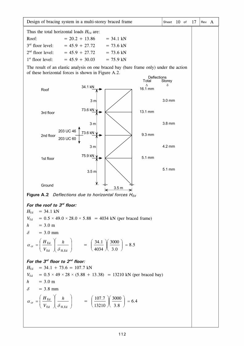
Design of bracing system in a multi-storey braced frame Sheet 10 of 17 Rev A
112
Thus the total horizontal loads HEd are:
Roof: = 20.2 + 13.86 = 34.1 kN
3rd floor level: = 45.9 + 27.72 = 73.6 kN
2nd floor level: = 45.9 + 27.72 = 73.6 kN
1st floor level: = 45.9 + 30.03 = 75.9 kN
The result of an elastic analysis on one braced bay (bare frame only) under the action of these horizontal forces is shown in Figure A.2.
3 m
3 m
3 m
3.5 m
3.5 m
203 UC 46
203 UC 60
DeflectionsTotal Storey
Roof
3rd floor
2nd floor
1st floor
Ground
34.1 kN
73.6 kN
73.6 kN
75.9 kN
5.1 mm
5.1 mm
4.2 mm
9.3 mm
3.8 mm
13.1 mm
3.0 mm
16.1 mm
Figure A.2 Deflections due to horizontal forces HEd
For the roof to 3rd floor: HEd = 34.1 kN
VEd = 0.5 × 49.0 × 28.0 × 5.88 = 4034 kN (per braced frame)
h = 3.0 m
= 3.0 mm
EdH,Ed
Edcr
h
V
H = 5.8
0.3
3000
4034
1.34
For the 3rd floor to 2nd floor: HEd = 34.1 + 73.6 = 107.7 kN
VEd = 0.5 × 49 × 28 × (5.88 + 13.38) = 13210 kN (per braced bay)
h = 3.0 m
= 3.8 mm
EdH,Ed
Edcr
h
V
H = 4.6
8.3
3000
13210
7.107

Design of bracing system in a multi-storey braced frame Sheet 11 of 17 Rev A
113
For the 2nd floor to 1st floor: HEd = 34.1 + 73.6 +73.6 = 181.3 kN
VEd = 0.5 × 49 × 28 × (5.88 + 13.38 + 13.38) = 22390 kN (per braced bay)
h = 3.0 m
= 4.2 mm
EdH,Ed
Edcr
h
V
H = 8.5
2.4
3000
22390
3.181
For the 1st floor to ground: HEd = 34.1 + 73.6 +73.6 + 75.9 = 257.2 kN
VEd = 0.5 × 49 × 28 × (5.88 + 13.38 + 13.38 + 13.38) = 31570 kN (per braced bay)
h = 3.5 m
= 5.1 mm
EdH,Ed
Edcr
h
V
H = 6.5
1.5
3500
31570
2.257
Therefore, for the worst case, cr = 5 .6
Since cr < 10, first order analysis alone is not sufficient. Second order effects must be allowed for. These second order effects will be allowed for by amplification of the lateral loads, in accordance with 5.2.2(6)B, which is allowed provided that cr 3 and the frame is regular in loading and stiffness (which it is in this case).
BS EN 1993-1-1 5.2.1 (3)
The horizontal load amplifier is given by:
cr
11
1
5.2.2 (5)B Eqn (5.4)
Therefore the load amplifier for Combination 1 is 22.1
6.5
11
1
Therefore the lateral loads in Combination 1 (the wind loads and the EHF) will be increased by 22% to allow for second order effects.
Frame stability in Combination 2
From Table A.1, in Combination 2, the design values of combined vertical load are:
Roof: 5.13 kN/m2
Floor: 10.68 kN/m2
Thus the EHF per floor, per bracing plane, are:
Roof: 0.005 (0.5 28.0 m 49.0 m) 5.13 kN/m2 = 17.6 kN
Floor: 0.005 (0.5 28.0 m 49.0 m) 10.68 kN/m2 = 36.6 kN
The wind loads per floor are also given in Section A.5 as 27.72 kN, 55.4 kN, 55.4 kN and 60.1 kN, for the roof, 3rd, 2nd and 1st floors respectively.
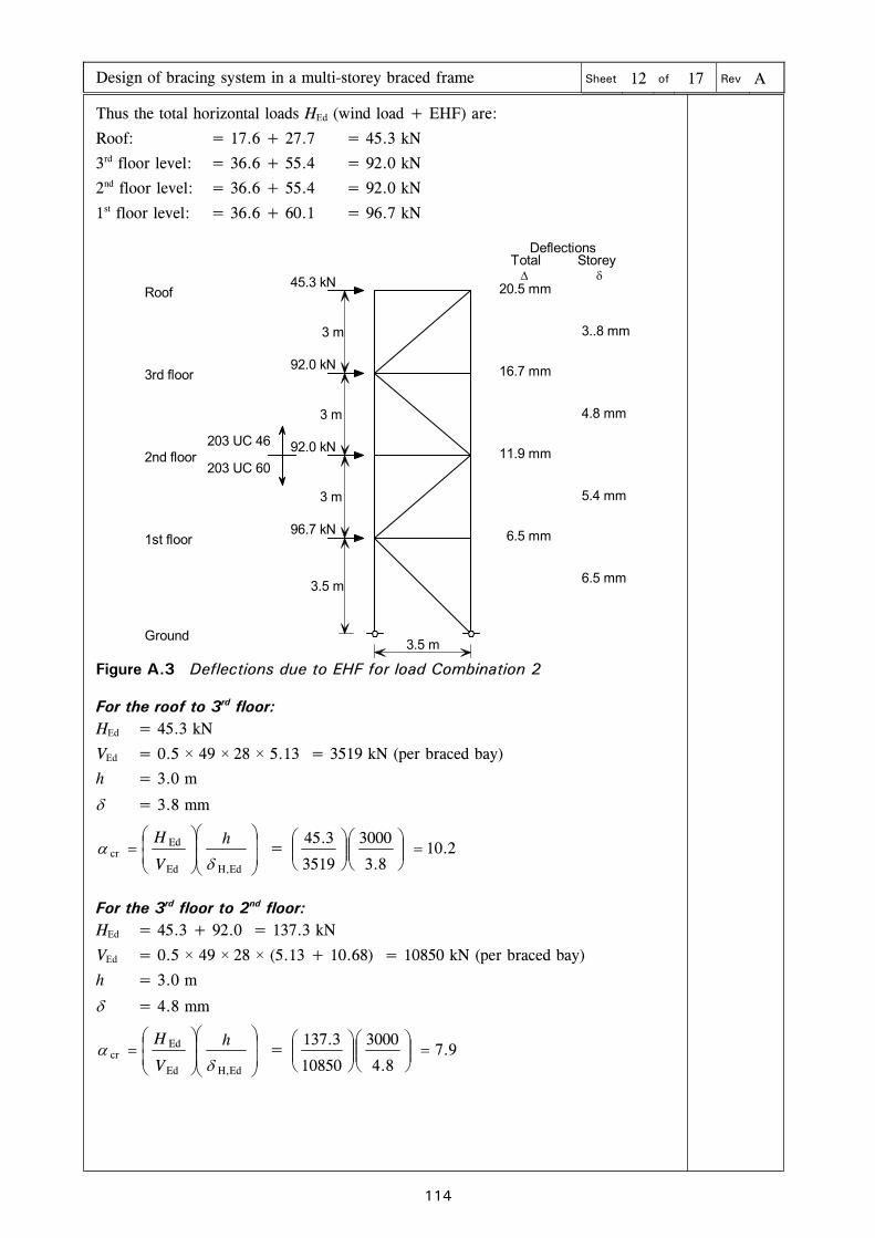
Design of bracing system in a multi-storey braced frame Sheet 12 of 17 Rev A
114
Thus the total horizontal loads HEd (wind load + EHF) are:
Roof: = 17.6 + 27.7 = 45.3 kN
3rd floor level: = 36.6 + 55.4 = 92.0 kN
2nd floor level: = 36.6 + 55.4 = 92.0 kN
1st floor level: = 36.6 + 60.1 = 96.7 kN
203 UC 46
203 UC 60
DeflectionsTotal Storey
Roof
3rd floor
2nd floor
1st floor
Ground
3 m
3 m
3 m
3.5 m
3.5 m
45.3 kN
92.0 kN
92.0 kN
96.7 kN
20.5 mm
16.7 mm
3..8 mm
4.8 mm
11.9 mm
5.4 mm
6.5 mm
6.5 mm
Figure A.3 Deflections due to EHF for load Combination 2
For the roof to 3rd floor: HEd = 45.3 kN
VEd = 0.5 × 49 × 28 × 5.13 = 3519 kN (per braced bay)
h = 3.0 m
= 3.8 mm
EdH,Ed
Edcr
h
V
H = 2.10
8.3
3000
3519
3.45
For the 3rd floor to 2nd floor: HEd = 45.3 + 92.0 = 137.3 kN
VEd = 0.5 × 49 × 28 × (5.13 + 10.68) = 10850 kN (per braced bay)
h = 3.0 m
= 4.8 mm
EdH,Ed
Edcr
h
V
H = 9.7
8.4
3000
10850
3.137

Design of bracing system in a multi-storey braced frame Sheet 13 of 17 Rev A
115
For 2nd floor to 1st floor: HEd = 45.3 + 92.0 + 92.0 = 229.3 kN
VEd = 0.5 × 49 × 28 × (5.13 + 10.68+ 10.68) = 18170 kN (per braced bay)
h = 3.0 m
= 5.4 mm
EdH,Ed
Edcr
h
V
H = 0.7
4.5
3000
18170
3.229
For 1st floor to ground: HEd = 45.3 + 92.0 + 92.0 + 96.7 = 326.0 kN
VEd = 0.5 × 49 × 28 × (5.13 + 10.68+ 10.68+ 10.68) = 25500 kN (per braced bay)
h = 3.5 m
= 6.5 mm
EdH,Ed
Edcr
h
V
H = 9.6
5.6
3500
25500
0.326
Therefore, for the worst case αcr = 6.9
Since cr < 10, first order analysis alone is not sufficient. Second order effects must be allowed for. These second order effects will be allowed for by amplification of the lateral loads, in accordance with 5.2.2(6)B, which is allowed provided that cr 3 and the frame is regular in loading and stiffness (which it is in this case).
BS EN 1993-1-1 5.2.1 (3)
The horizontal load amplifier is given by:
cr
11
1
5.2.2 (5)B Eqn (5.4)
Therefore the load amplifier is 17.1
9.6
11
1
Therefore the lateral loads in Combination 2 (the wind loads and the EHF) will be increased by 17% to allow for second order effects.

Design of bracing system in a multi-storey braced frame Sheet 14 of 17 Rev A
116
A.8 Design of bracing
The diagonal bracing is designed based on the results from the first order analysis, amplified as necessary, under combinations 1 and 2.
The diagonal bracing between ground level and first floor level is the most heavily loaded member and it may be in tension or compression. It will be designed for the more onerous compressive force. The first order forces, the amplification factors and the design forces are shown below.
Combination 1 Horizontal force, 1st floor to ground = 257.2 kN
Diagonal member axial force (compression) = 257.2 × 2 = 363.7 kN
Amplification factor = 1.22
Therefore the member axial design force = 363.7 × 1.22 = 443.7 kN
Sheet 11
Combination 2 Horizontal force, 1st floor to ground = 326.0 kN Diagonal member axial force (compression = 326 × 2 = 461.0 kN
Amplification factor = 1.17
Therefore the member axial design force = 461.0 × 1.17 = 539.4 kN
The diagonal brace member between ground level and first floor level is to be designed to resist a 539.4 kN compressive force.
Sheet 13
A 168× 6.3 circular hollow section member was used for the diagonal bracing in the analysis to obtain sway displacements. This member will be checked to determine whether it is sufficient to resist the 539.4 kN design force in compression.
Member checks
Buckling length Hollow sections acting as diagonal bracing in compression are usually assumed to have an effective length factor of 1.0, as gusset plate details are relatively flexible out of plane. The member length is calculated between the intersections of column and beam axes.
As there are no intermediate restraints the effective length (Lcr) is:
Lcr = 1.0 × 4950 = 4950 mm.
Slenderness for flexural buckling For flexural buckling, the non-dimensional slenderness is given by:
1
cr
cr
y 1
i
L
N
Af (For Class 1, 2 and 3 cross sections)
6.3.1.3 (1) Eqn. (6.50)
81.0355235235 y f
06.7681.09.939.931
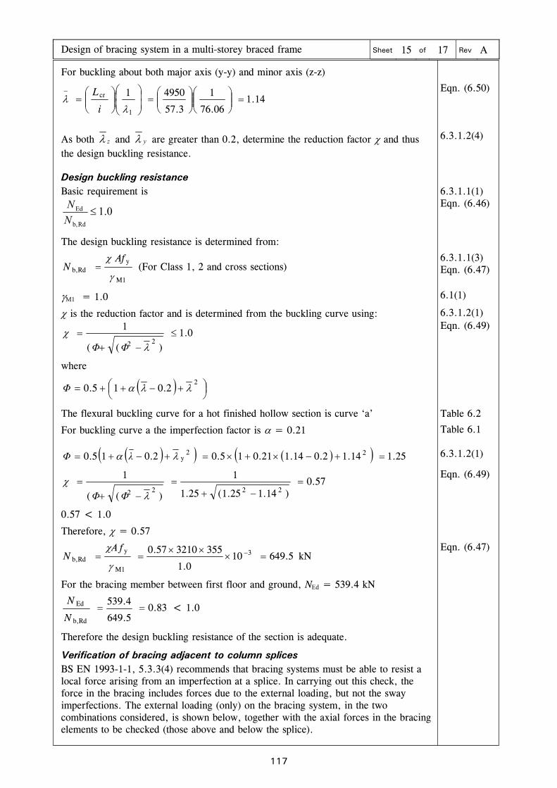
Design of bracing system in a multi-storey braced frame Sheet 15 of 17 Rev A
117
For buckling about both major axis (y-y) and minor axis (z-z)
14.106.76
1
3.57
49501
1
cr
i
L
Eqn. (6.50)
As both z and y are greater than 0.2, determine the reduction factor and thus the design buckling resistance.
6.3.1.2(4)
Design buckling resistance Basic requirement is
0.1Rdb,
Ed N
N
6.3.1.1(1) Eqn. (6.46)
The design buckling resistance is determined from:
M1
yRdb,
AfN (For Class 1, 2 and cross sections)
6.3.1.1(3) Eqn. (6.47)
M1 = 1.0 6.1(1)
is the reduction factor and is determined from the buckling curve using: 6.3.1.2(1)
0.1)((
122
ΦΦ
where
22.015.0 Φ
Eqn. (6.49)
The flexural buckling curve for a hot finished hollow section is curve ‘a’ Table 6.2
For buckling curve a the imperfection factor is = 0.21 Table 6.1
25.114.12.014.121.015.02.015.0 22y λΦ 6.3.1.2(1)
57.0)14.125.1(25.1
1
)((
12222
ΦΦ
0.57 < 1.0
Therefore, = 0.57
Eqn. (6.49)
5.649100.1
355321057.0 3
M1
yRdb,
fAN kN
Eqn. (6.47)
For the bracing member between first floor and ground, NEd = 539.4 kN
83.05.649
4.539
Rdb,
Ed N
N < 1.0
Therefore the design buckling resistance of the section is adequate.
Verification of bracing adjacent to column splices
BS EN 1993-1-1, 5.3.3(4) recommends that bracing systems must be able to resist a local force arising from an imperfection at a splice. In carrying out this check, the force in the bracing includes forces due to the external loading, but not the sway imperfections. The external loading (only) on the bracing system, in the two combinations considered, is shown below, together with the axial forces in the bracing elements to be checked (those above and below the splice).

Design of bracing system in a multi-storey braced frame Sheet 16 of 17 Rev A
118
13.9
27.7
27.7
30.0
54.754.754.754.7
140.4
91.2
27.7
55.4
55.4
60.1
145.9
218.9
320.0
Combination 1 Combination 2
The total force to be resisted is a proportion of the total axial force in every column spliced at that level. It is assumed that each of the 42 columns is spliced at the same level, at the second storey.
The local force is given as 1000Edm N
where
m
115.0m and m is the number of columns to be restrained.
m
115.0m =
42
115.0m = 0.72
Combination 1 Total axial force in columns = 5.88 × 49 × 28 + 13.38 × 49 × 28 = 26430 kN
Local force per bracing system = 0.5 × 0.72 × 100
26430 = 95.1 kN
Combination 2 Total axial force in columns = 5.13 × 49 × 28 + 10.68 × 49 × 28 = 21690 kN
Local force per bracing system = 0.5 × 0.72 × 100
21690 = 78.1 kN
5.3.3(4)
Assuming the local force is split equally between each bracing member, the resultant force in the diagonal member between 2nd and 1st floor levels is 62.6 kN in Combination 1 and 51.5 kN in Combination 2.
The total maximum force in this member is:
91.2 + 62.6 = 153.8 kN in Combination 1
218.9 + 51.5 = 270.4 kN in Combination 2
As the bracing member is the same as at 1st to ground floor, where it can resist 649.5 kN over a slightly longer member length, the local imperfection forces at splices can be carried by the bracing.
95.1
62.6
40.8
47.6

Design of bracing system in a multi-storey braced frame Sheet 17 of 17 Rev A
119
Verification of restraint to columns provided by bracing BS EN 1993-1-1, 5.3.2(5) recommends that bracing systems should be able to resist a local force required to restrain the column(s) at that level. In carrying out this check, the force in the bracing includes forces due to the external loading, but not the sway imperfections.
5.3.2(5)
The total force to be carried by the bracing locally is given as H = NEd, where is to be taken from 5.3.2(3), assuming a single storey column. With this proviso, h = 1.0
In this example frame, the largest restraint forces will arise at the first floor level, where the axial load in the columns is a maximum.
= 0 h m
where h = 1.0 and
m
115.0m =
421
15.0 = 0.72
0036.072.02001
Combination 1 Total axial force in columns = 5.88 × 49 × 28 + 13.38 × 49 × 28 × 3
= 63140 kN
Local force per bracing system = 0.5 × 0.0036 × 63140 = 113 kN
Combination 2 Total axial force in columns = 5.13 × 49 × 28 + 10.68 × 49 × 28 × 3
= 51000 kN
Local force per bracing system = 0.5 × 0.0036 × 51000 = 91.8 kN
Assuming the local force is split equally between each bracing member, the resultant force in the diagonal member is 74.5 kN in Combination 1 and 60.5 kN in combination 2.
The total maximum force locally becomes:
140.4 + 74.5 = 214.9 kN in combination 1
320.0 + 60.5 = 380.5 kN in combination 2
As the member resistance of the 1st to ground floor bracing is 649.5 kN, it is adequate for these forces.
This example serves to demonstrate that in most cases, reasonable, orthodox bracing, designed to carry the combination of the EHF and the externally applied wind loads will be capable of carrying the local forces due to imperfections at splices, and the local restraint forces at floor levels.
In a complete design, the columns forming the bracing system would need to be checked in combination with the axial forces from the roof and floor loads, in the appropriate load combinations. In most cases, the chosen columns will be the same size as internal columns, but carrying rather less axial load.


