76
SCOTTY Teleport Software Manual

SCOTTY Teleport Software Manual

Disclaimer
Copyright SCOTTY Group Austria GmbH. All rights reserved. SCOTTY Group Austria GmbH (SCOTTY) retains copyright in this manual and associated user documentation (the Documentation). The Documentation must not be reproduced or used for any purpose other than intended without written permission. The information provided in the Documentation is believed to be accurate and reliable; however, SCOTTY does not accept responsibility for loss or damage arising out of errors or omissions, and reserves the right to revise the documentation without notice. SCOTTY and its suppliers retain all copyright and other intellectual property rights in the software embedded in and associated with the product described in the documentation (the Software). Some products include software distributed under GNU General Public License (GPL); please contact SCOTTY for further information and source code. By purchasing the product described in the documentation you are granted a limited license to use the Software, provided you do not copy, alter or adapt the Software in any way including decompiling, disassembling or reverse-engineering. No liability for consequential damages. SCOTTY, the SCOTTY logo, TeleporterTM, and BeamerTM are Trademarks of SCOTTY.
Microsoft and Windows are registered Trademarks of Microsoft Corporation. Version V3.01.05 SD208270A This document is under electronic revision control.

SCOTTY Teleport Software Manual
All rights reserved. 3
Table of Contents
1 Welcome .............................................................................................7
1.1 Welcome ............................................................................................................. 7 1.2 About the Manuals .............................................................................................. 8 1.3 Customer Support ............................................................................................... 8
2 Quick Guide .......................................................................................9
2.1 Quick Guide ......................................................................................................... 9 2.2 Starting the SCOTTY Teleporter ........................................................................... 9 2.3 The Main Window ............................................................................................. 10 2.4 Making a Call ..................................................................................................... 10 2.5 Creating or Editing a Phone Book Entry ............................................................ 10 2.6 Receiving a Call .................................................................................................. 11 2.7 Terminating a Call .............................................................................................. 11 2.8 Muting Audio or Video during a Call ................................................................. 11 2.9 Changing the Volume ........................................................................................ 11 2.10 Changing the Camera ...................................................................................... 12 2.11 Controlling the Local Camera .......................................................................... 12 2.12 Controlling the Remote Camera ...................................................................... 12 2.13 Recording a Video ........................................................................................... 12 2.14 Playing Back a Video ........................................................................................ 13 2.15 Transfer of Files with Automatic Hang Up ...................................................... 13 2.16 Transfer of Files during a Video Call ................................................................ 13 2.17 Making a Video Snapshot ................................................................................ 14 2.18 Making and Sending a Video Snapshot ........................................................... 14 2.19 Monitor the Video on a Remote Device .......................................................... 14 2.20 Using the SCOTTY Footswitch.......................................................................... 15 2.21 Turning Off the System .................................................................................... 15
3 System Configuration ..................................................................... 17
3.1 System Configuration ........................................................................................ 17 3.2 The Configuration Utility ................................................................................... 18
3.2.1 The Setup Tab ............................................................................................ 18 3.2.2 The Video Tab ............................................................................................ 19 3.2.3 The Audio Tab ........................................................................................... 20 3.2.4 The Stream Tab ......................................................................................... 22 3.2.5 The LAN Tab .............................................................................................. 23 3.2.6 The Data Channels Tab .............................................................................. 26 3.2.7 The Shortcuts Tab...................................................................................... 27

SCOTTY Teleport Software Manual
4 All rights reserved.
3.2.8 The Remote Control Tab ........................................................................... 28 3.3 LAN Network Configuration .............................................................................. 29
4 Teleport Details ............................................................................... 31
4.1 Teleport Details ................................................................................................. 31 4.2 The Main Window............................................................................................. 32 4.3 The File Menu ................................................................................................... 34
4.3.1 Dial, Making a Call .................................................................................... 34 4.3.2 Creating or Modifying a Telephone Book Entry ....................................... 36 4.3.3 Format for Entering the Telephone Number ............................................ 37 4.3.4 Disconnect, Terminating a Call ................................................................. 38 4.3.5 Recorder, the Record and Play Mode....................................................... 38 4.3.6 File Transfer, Transfer Files Efficiently ...................................................... 40 4.3.7 Snap & Send, Sending Still Images ............................................................ 42 4.3.8 Snapshot, Taking a Still Picture ................................................................. 42 4.3.9 Exit, Ending the Program .......................................................................... 42
4.4 The View Menu ................................................................................................. 43 4.4.1 Video Window, Manipulating the Video Window .................................... 43 4.4.2 Fullscreen Video Window, Activating Full Screen .................................... 43 4.4.3 Camera Control, Controlling Local and Far End Cameras ......................... 44 4.4.4 Tone Pad, Playing DTMF Tones ................................................................ 46 4.4.5 Audio & Video Controls ............................................................................ 47 4.4.6 Pic In Pic, Setting the Picture in Picture view ........................................... 49 4.4.7 Toolbars, Manipulating the Toolbars ....................................................... 49 4.4.8 Received Files, Listing the Received Files ................................................. 50 4.4.9 Recorded Files, View recorded Files ......................................................... 51 4.4.10 Connection Info, Displaying the Connection Status ............................... 51
4.5 The Options Menu ............................................................................................ 52 4.5.1 Dialing, Setting the Dialing Parameters .................................................... 52 4.5.2 Audio, Setting the Audio Levels ................................................................ 53 4.5.3 Transmit, Setting Audio and Video Parameters ....................................... 55 4.5.4 Data, Adjusting the Data Channel Parameters ......................................... 56 4.5.5 Directories, Setting the SCOTTY Directory Structure................................ 58 4.5.6 Preferences, Setting the System Parameters ........................................... 59 4.5.7 File Exchange ............................................................................................ 60 4.5.8 Save, Saving the Current Settings ............................................................. 60 4.5.9 Factory Defaults, Restoring the Factory Defaults ..................................... 61
4.6 The Help Menu ................................................................................................. 62 4.6.1 Help Topics, the SCOTTY Help System ...................................................... 62 4.6.2 Open Manual, View System Documentation ........................................... 62 4.6.3 About Teleporter, Displaying the SCOTTY Configuration ......................... 63
5 System Recover .............................................................................. 65
5.1 Restoring the System ........................................................................................ 66 5.2 Restoring the System using a Recovery Stick ................................................... 68 5.3 Creation of a User defined Hard Disk Image .................................................... 69 5.4 Creation of New Recover Stick ......................................................................... 70 5.5 Full System Backups .......................................................................................... 71
6 Software Specifications .................................................................. 73
6.1 Overview ........................................................................................................... 73
SCOTTY Teleport Software Manual
All rights reserved. 5
6.2 Video Conference and Live Video Transmission ............................................... 73 6.3 Recording ........................................................................................................... 74 6.4 Streaming .......................................................................................................... 74 6.5 Windows Video Overlay .................................................................................... 74 6.6 Snapshot ............................................................................................................ 74 6.7 Video Input Formats .......................................................................................... 75 6.8 Video Output Formats ....................................................................................... 76

SCOTTY Teleport Software Manual
6 All rights reserved.
This page intentionally left blank.
SCOTTY Teleport Software Manual
All rights reserved. 7
1 Welcome
1.1 Welcome Welcome to the world of advanced communication... welcome to the world of SCOTTY!
SCOTTY provides a unique offering of live HD video, audio, and data communication, live HD video surveillance transmission, and imagery transfer from air, land, and sea – over satellite and terrestrial networks. This package is used by customers around the world to support their border control, intelligence gathering, reconnaissance, surveillance, search and rescue, and other missions which require beyond line-of-sight connectivity and ruggedized/reliable equipment.
SCOTTY is EN9100 certified and has over fifteen years' experience serving customers around the world.
Please find detailed information on our website: www.scottygroup.com

SCOTTY Teleport Software Manual
8 All rights reserved.
1.2 About the Manuals The Equipment Manual describes the hardware aspects of your SCOTTY system, serving as a valuable source of information not only for integrators but also for users.
The Software Manual accompanies the Equipment Manual. It describes the software aspects of your SCOTTY system, and is geared toward the user and administrator.
Both manuals help you take full advantage of your SCOTTY solution. They are not only a comprehensive guide to the operation of the system, they also provide technical details, simple step by step instructions on how to perform the most common applications, and more. We recommend you read the manuals carefully in order to fully benefit from SCOTTY's advanced solutions.
Furthermore, Quick Reference Guides are available describing the basic functionality on a single page – these are suitable for daily use.
1.3 Customer Support The Support section on our website www.scottygroup.com offers help to maximize the functionality of your SCOTTY system.
Choose Downloads to retrieve the latest documents, manuals and software.
Find updated information about our demo numbers to place demonstration and test calls to our demonstration systems.
Find out how to get in contact with our support experts.
Please help our support team provide the best support possible by including the serial number of your SCOTTY unit in all requests.

SCOTTY Teleport Software Manual
All rights reserved. 9
2 Quick Guide
2.1 Quick Guide In the following section we want to make the user familiar with the basic functions of the SCOTTY Teleporter software. Making a professional videoconference, using the quick file transfer feature, recording and playing back videos and additional features of the Teleporter are described step by step to be carried out very easily.
For further details, see the following chapters.
2.2 Starting the SCOTTY Teleporter
Step 1: Switch on the unit as described in the Hardware Manual, Windows loads itself automatically.
Step 2: When Windows is ready, choose the Teleporter icon on the desktop.
The SCOTTY Teleport application can be configured for auto start operation. Step 2 is not necessary in such a setup.

SCOTTY Teleport Software Manual
10 All rights reserved.
2.3 The Main Window After starting the SCOTTY Teleporter, it takes a few moments for the system to initialize. The running initialization steps are displayed in the status bar at the bottom of the Main Window. Video-communication is ready to begin once this process is complete.
The SCOTTY Teleporter Main Window
SCOTTY video-communication is as easy as placing a telephone call. The most often used functions are accessible by tool buttons. These and all other functions are also available using the menu bar.
2.4 Making a Call
Step 1: From the standard toolbar of the SCOTTY main window select the Dial button.
Step 2: Select the entry of the desired party.
Alternatively you can directly enter the phone number or IP address into the Number edit field. Clicking the button Pad opens a dial pad which can be used to enter the number with the input device.
Step 3: Press Dial to start the call using the default dialing parameter.
Press Low Cost to start the call with reduced bandwidth.
2.5 Creating or Editing a Phone Book Entry
Step 1: From the standard toolbar of the SCOTTY main window select the Dial button.
Step 2 Click the New Entry or the Edit Entry button.
There are several ways of addressing a videoconferencing partner: IP-address
(e.g. 91.209.75.198), hostname (e.g. demograz.scottygroup.com), or using a gatekeeper. See chapter 4.3.3 for details.
SCOTTY Teleport Software Manual
All rights reserved. 11
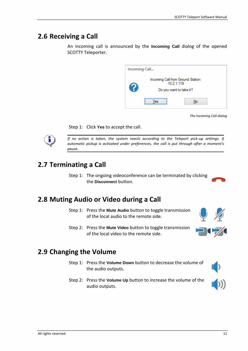
2.6 Receiving a Call An incoming call is announced by the Incoming Call dialog of the opened SCOTTY Teleporter.
The Incoming Call dialog
Step 1: Click Yes to accept the call.
If no action is taken, the system reacts according to the Teleport pick-up settings. If automatic pickup is activated under preferences, the call is put through after a moment's pause.
2.7 Terminating a Call
Step 1: The ongoing videoconference can be terminated by clicking the Disconnect button.
2.8 Muting Audio or Video during a Call
Step 1: Press the Mute Audio button to toggle transmission of the local audio to the remote side.
Step 2: Press the Mute Video button to toggle transmission of the local video to the remote side.
2.9 Changing the Volume
Step 1: Press the Volume Down button to decrease the volume of the audio outputs.
Step 2: Press the Volume Up button to increase the volume of the audio outputs.

SCOTTY Teleport Software Manual
12 All rights reserved.
2.10 Changing the Camera
Step 1: Select a camera and audio preset.
The Audio & Video Controls dialog defines the presets and enables flexible setting of the audio and video parameters. It can be opened with View | Audio&Video Controls...
2.11 Controlling the Local Camera
Step 1: Activate the camera dialog with View | Camera Control.
Step 2: Click on the Local tab.
Step 3: Control the camera with the available buttons.
2.12 Controlling the Remote Camera
Step 1: Establish a videoconference.
Step 2: Activate the camera dialog with View | Camera Control.
Step 3: Click on the Remote tab.
Step 4: Use Video Source to select the remote video input.
Step 5: Control the camera with the available buttons.
2.13 Recording a Video
Step 1: From the standard toolbar of the SCOTTY main window select the Recorder button.
Step 2: Start the recording.
Step 3: Stop recording. The recording is saved with an automatically assigned name.
Step 4: The name of the saved recording is now displayed in the field File of the section "Play" and can be played back with the Play button if desired.

SCOTTY Teleport Software Manual
All rights reserved. 13
2.14 Playing Back a Video
Step 1: From the standard toolbar of the SCOTTY main window select the Recorder button (optional).
Step 2: In the section "Play" choose the Browse button, select one of the recorded files on the hard drive and choose Open. To play back a previously received file, browse to the Incoming directory.
Step 3: Press the Play button.
2.15 Transfer of Files with Automatic Hang Up
Step 1: From the standard toolbar of the SCOTTY main window select the File Transfer button.
Step 2: Click on Add.
Step 3: In the "Open" dialog select the file to transmit and press Open.
Step 4: Repeat Step 2 and Step 3 to add several files to the displayed list.
Step 5: Click on Send.
Step 6: Double-click the desired party.
The SCOTTY File Transfer is possible between two SCOTTY systems using Teleporter or the File Transfer software.
2.16 Transfer of Files during a Video Call
Step 1: Establish a videoconference.
Step 2: After connection has been established, select the File
Transfer button.
Step 3: Click on Add.
Step 4: In the "Open" dialog select the file to transmit and press Open.
Step 5: Repeat Step 3 and Step 4 to add several files to the list.
Step 6: Click on Send.
The SCOTTY File Transfer is possible between two SCOTTY systems using Teleporter or the File Transfer software.
SCOTTY Teleport Software Manual
14 All rights reserved.
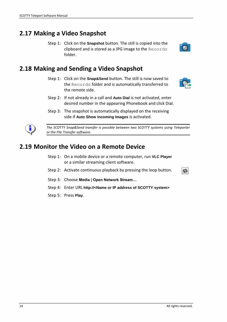
2.17 Making a Video Snapshot
Step 1: Click on the Snapshot button. The still is copied into the
clipboard and is stored as a JPG image to the Records folder.
2.18 Making and Sending a Video Snapshot
Step 1: Click on the Snap&Send button. The still is now saved to
the Records folder and is automatically transferred to the remote side.
Step 2: If not already in a call and Auto Dial is not activated, enter desired number in the appearing Phonebook and click Dial.
Step 3: The snapshot is automatically displayed on the receiving side if Auto Show incoming Images is activated.
The SCOTTY Snap&Send transfer is possible between two SCOTTY systems using Teleporter or the File Transfer software.
2.19 Monitor the Video on a Remote Device
Step 1: On a mobile device or a remote computer, run VLC Player or a similar streaming client software.
Step 2: Activate continuous playback by pressing the loop button.
Step 3: Choose Media | Open Network Stream…
Step 4: Enter URL http://<Name or IP address of SCOTTY system>
Step 5: Press Play.
SCOTTY Teleport Software Manual
All rights reserved. 15
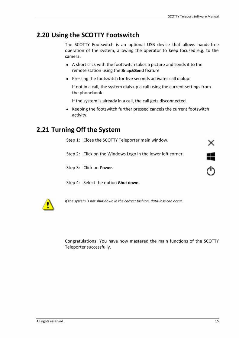
2.20 Using the SCOTTY Footswitch The SCOTTY Footswitch is an optional USB device that allows hands-free operation of the system, allowing the operator to keep focused e.g. to the camera.
A short click with the footswitch takes a picture and sends it to the remote station using the Snap&Send feature
Pressing the footswitch for five seconds activates call dialup:
If not in a call, the system dials up a call using the current settings from the phonebook
If the system is already in a call, the call gets disconnected.
Keeping the footswitch further pressed cancels the current footswitch activity.
2.21 Turning Off the System
Step 1: Close the SCOTTY Teleporter main window.
Step 2: Click on the Windows Logo in the lower left corner.
Step 3: Click on Power.
Step 4: Select the option Shut down.
If the system is not shut down in the correct fashion, data-loss can occur.
Congratulations! You have now mastered the main functions of the SCOTTY Teleporter successfully.

SCOTTY Teleport Software Manual
16 All rights reserved.
This page intentionally left blank.

SCOTTY Teleport Software Manual
All rights reserved. 17
3 System Configuration
3.1 System Configuration The system’s software is already pre-defined for easy operation. Neverthless, after initial system setup or when the setup is changed, the software might need to be re-configured.
This chapter describes the configuration of the Teleport application using the Configuration Utility, and global Windows settings needed for Teleport operation. Please refer to Microsoft literature for the configuration of other Windows settings.
Further settings can be configured inside the Teleport application; for more information see chapter 4.
Because all settings will be restored to factory defaults by a system recovery (Option), it can be advisable to create a new recovery image after changing the system configuration. See chapter 5 for details.

SCOTTY Teleport Software Manual
18 All rights reserved.
3.2 The Configuration Utility The SCOTTY Configuration Utility enables the user to define system settings. By choosing Start | All Apps | Scotty | Config, the SCOTTY Configuration Utility window is opened.
When pressing OK, the settings are saved and will take effect on the Teleporter software the next time it is started.
Depending on your system, the Configuration Utility might show different settings than depicted in this chapter.
3.2.1 The Setup Tab
The Setup tab displays the configuration of the installed system. The configuration of the system can only be changed when a new key is provided by SCOTTY.
The Configuration Utility, folder Setup
By pressing the Change… button the new key can be entered.
Pressing the Modify Options button opens a dialog which provides, after consultation with SCOTTY, an easy way to change the system configuration without editing the key manually. Free key-tokens can be added or removed manually in this way. The Add button is used to add, the Remove button to delete, and the Modify button to change entries.

SCOTTY Teleport Software Manual
All rights reserved. 19
3.2.2 The Video Tab
In the folder Video, the video setup can be configured.
The Configuration Utility, folder Video
In Video Inputs the configuration of the four logical video inputs and the equipment connected to them are defined.
The physical input and its video format assigned to the logical input are defined under Input. A logical input can be disabled by choosing Not Used.
The field Equipment selects which controllable equipment is connected to the input. Video Source specifies a non-controllable video source.
If controllable equipment is set in Equipment, the serial port for camera control can be selected in Control Port. Some camera types support chaining to connect two cameras to a single control port; select Pos2 for the chained camera.
Analog HD Output enables selecting the format of the high definition codec output.
Under Analog SD Output the standard definition codec output can be configured.
The field Standard enables the user to change the video standard of the output between PAL and NTSC.
The physical video output and its video format are selectable under Format.

SCOTTY Teleport Software Manual
20 All rights reserved.
3.2.3 The Audio Tab
The folder Audio enables the configuration of the audio inputs and outputs.
The Configuration Utility, folder Audio
The section Audio Inputs enables the configuration of the audio inputs.
Selecting Stereo means two microphones are bundled together as a stereo input, or a line level input is used in stereo mode.
Choosing 2x Mono enables the use two microphones as two independent mono inputs.
Configuring Mono will use one channel as a mono input.
The selection Line Mode will use the Line input as an acoustic source; intended for the connection of a microphone system or similar.
Mic Mode will activate a microphone pre-amplifier, enabling the connection of low-signal sources; please note that it will not activate any phantom power.
The choice Aux Mode will switch the Line input into auxiliary mode.
The Aux input is always configured to auxiliary mode, see below.
Auxiliary mode activates local hearing of the audio signal. It is intended for the connection of external playback devices which can be heard both by the local and remote audience.

SCOTTY Teleport Software Manual
All rights reserved. 21
Under Audio Outputs the audio outputs are configured.
Selecting Stereo will configure an output into stereo mode.
Configuring Mono will use one channel of the output as a mono output.
The Aux output operates in auxiliary mode (see below). On systems without Aux output, the Line output is configurable:
The selection Line Mode will use the Line output as an acoustic output; intended for the connection of a speaker system or similar.
The choice Aux Mode will switch the Line output into auxiliary mode.
Auxiliary mode activates the output of both the remote and the local audio signal. It is intended for monitoring or for the connection of external recording devices.
SCOTTY Teleport Software Manual
22 All rights reserved.
3.2.4 The Stream Tab
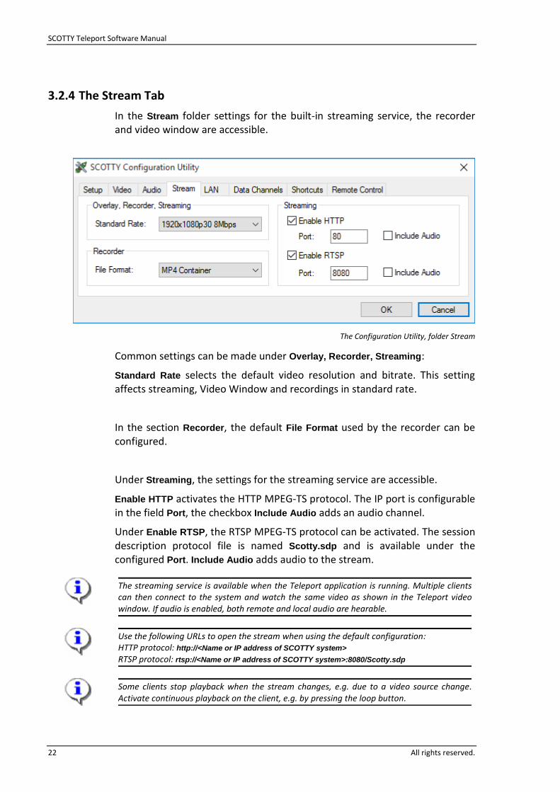
In the Stream folder settings for the built-in streaming service, the recorder and video window are accessible.
The Configuration Utility, folder Stream
Common settings can be made under Overlay, Recorder, Streaming:
Standard Rate selects the default video resolution and bitrate. This setting affects streaming, Video Window and recordings in standard rate.
In the section Recorder, the default File Format used by the recorder can be configured.
Under Streaming, the settings for the streaming service are accessible.
Enable HTTP activates the HTTP MPEG-TS protocol. The IP port is configurable in the field Port, the checkbox Include Audio adds an audio channel.
Under Enable RTSP, the RTSP MPEG-TS protocol can be activated. The session description protocol file is named Scotty.sdp and is available under the configured Port. Include Audio adds audio to the stream.
The streaming service is available when the Teleport application is running. Multiple clients can then connect to the system and watch the same video as shown in the Teleport video window. If audio is enabled, both remote and local audio are hearable.
Use the following URLs to open the stream when using the default configuration: HTTP protocol: http://<Name or IP address of SCOTTY system>
RTSP protocol: rtsp://<Name or IP address of SCOTTY system>:8080/Scotty.sdp
Some clients stop playback when the stream changes, e.g. due to a video source change. Activate continuous playback on the client, e.g. by pressing the loop button.

SCOTTY Teleport Software Manual
All rights reserved. 23
3.2.5 The LAN Tab
The LAN is used to configure the network settings.
The Configuration Utility, folder LAN
A H.323 gatekeeper is a central unit that allows dialing into videoconference systems on a network by a unique name or number, regardless of their current IP address.
To connect the system with a Gatekeeper select Use Gatekeeper. Either select Auto Discovery or manually enter the IP Address of the gatekeeper.
Registration information contains the system name that can be entered in the Name field and the telephone number; this number can be entered in the Number field. This information is used to register the system with the gatekeeper.
For settings of the physical LAN interface see chapter 3.3.

SCOTTY Teleport Software Manual
24 All rights reserved.
Pressing the NAT/Firewall… button shows the advanced configuration, e.g. for tunneling through a Firewall, or making calls through a router.
LAN configuration tab, LAN/Firewall configuration
NAT, Network Address Translation, is often used when a videoconferencing system is connected to a router or firewall. The NAT support of the videoconferencing system enables connections through firewalls and routers that do not feature H.323 support. NAT support is enabled by selecting Enable
NAT and entering the global or external IP-address of the router into the IP
Address field.
The system will dynamically allocate which ports to use for TCP and UDP connections. To limit the outgoing and incoming ports to a specific range activate Use specified Port Ranges and enter both starting port number in the UDP Base Port / TCP Base Port fields and the number of the following ports in the UDP Port Count / TCP Port Count fields.
For reliable videoconferencing between networks, the Port Count number should be 10 or higher.
To tunnel through a router, Firewall or similar that does not support H.323, activate Enable NAT and Use specified Port Ranges. The specified ports must then be opened to allow traffic through the Firewall (also known as port forwarding). Additionally, the following ports are used by the system and should be opened as well: 1718, 1719 and 1720.

SCOTTY Teleport Software Manual
All rights reserved. 25
Pressing the File Transfer… button allows the configuration of SCOTTY File Transfer port.
By default, the Default port (14000) is used both for incoming and outgoing transfers. By selecting User-defined port, a different port value can be entered into the Listening Port field.
LAN configuration tab, LAN File transfer configuration
For file transfer during a video call, both parties need to be configured to the same port settings.

SCOTTY Teleport Software Manual
26 All rights reserved.
3.2.6 The Data Channels Tab
The Data Channels tab can be used to configure the external data channels.
The Configuration Utility, folder Data Channels
The position information supplied by an external NMEA source, like a GPS unit, can be used to tag snapshots taken by the Teleport application. Choosing Enable in the NMEA field will configure the Teleport application to use the selected serial RS232 port as information source.
The system will decode the latitude, longitude, altitude, date and time from NMEA $GPRMC and $GPGGA sequences.
The current status of the received position information can be viewed in the Teleport application under Help | About Teleporter.
Choosing Enable in the Serial Data Channel field will enable a transparent data connection of the selected serial RS232 interface in parallel to the video conference. Serial Data Channel needs to be activated on the other SCOTTY endpoint.
It is possible to choose the same COM port for both NMEA and Serial Data Channel, assuming that both are configured to the same Baud rate. In this way, the position information from an external GPS can be used both to tag local snapshots and to track the system on the remote side.

SCOTTY Teleport Software Manual
All rights reserved. 27
3.2.7 The Shortcuts Tab
With the Shortcuts tab, the Teleport shortcuts in the Start Menu and on the Desktop can be enabled or disabled.
The Configuration Utility, folder Shortcuts
Enabling Teleport in Autostart automatically starts Teleport at login of the current user.
If supported by the hardware of the SCOTTY system, additional shortcuts for special communication or encryption devices are displayed. Activating a shortcut option will place the corresponding Teleport shortcut on the desktop of the current user.
All SCOTTY shortcuts can be found on the Windows Start Menu under Start |
All Apps | Scotty.

SCOTTY Teleport Software Manual
28 All rights reserved.
3.2.8 The Remote Control Tab
The SCOTTY Remote Control functionality makes it possible to remotely control the SCOTTY Teleport, for example by a touch panel media control.
The Configuration Utility, folder Remote Control
To control the SCOTTY Teleport via LAN, click on Enable in the Telnet Access field. Define a Username and Password to prevent unauthorized access. Activate Enable Echo if the characters entered at the remote site shall be echoed by the SCOTTY system.
Clicking on Enable in the Serial Access field activates controlling SCOTTY Teleport using a serial RS232 interface. The control device has to be connected to the chosen Port using the selected Baudrate.
Please contact your SCOTTY representative for additional information about the SCOTTY Remote Control functionality.

SCOTTY Teleport Software Manual
All rights reserved. 29
3.3 LAN Network Configuration The internet protocol settings need to be configured according to the requirements of the local network access.
These settings are system-wide settings and are therefore accessible through the Windows operating system:
Right-click network symbol in the taskbar and choose Open network and
Sharing Center
Click on Change adapter settings
Select appropriate network adapter with the right mouse button and select Properties
Select appropriate Internet Protocol and click on Properties
IP and DNS settings can now be configured. Choose Obtain an IP address automatically to enable auto configuration respectively DHCP.
On some systems, the network adapter Codec is shown. Do not change its settings.
The procedure how to change the IP settings could vary between different versions of Windows; please refer to Microsoft literature for further details.

SCOTTY Teleport Software Manual
30 All rights reserved.
This page intentionally left blank.

SCOTTY Teleport Software Manual
All rights reserved. 31
4 Teleport Details
4.1 Teleport Details Based on many years of experience in the area of video-communication and user interfaces, SCOTTY systems are easy-to-use, multi-featured tools with clear user interfaces. All functions that are frequently used are directly available by clicking on buttons; the less used functions are found through the menus.
To avoid undesired changes to the Teleport configuration, new settings need to be saved manually. This way, Teleport will come up each time with well-defined settings. Alternatively, the system can be configured to auto-save settings; see chapters 4.5.8 and 4.5.6 for details.
On default, many Teleport settings are lost when SCOTTY Teleport is closed. To save settings permanently see chapter 4.5.8.
System recovery (optional) procedures will reset all user defined settings. See chapter 5 for details.
SCOTTY Teleport Software Manual
32 All rights reserved.
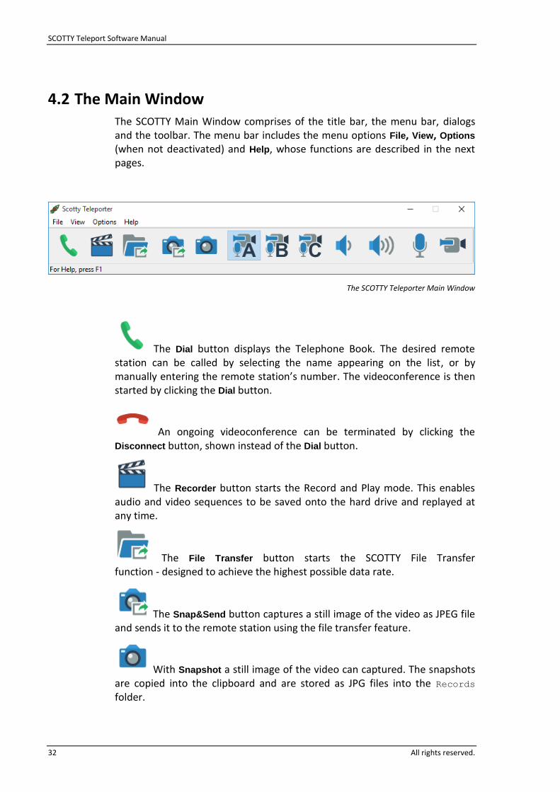
4.2 The Main Window The SCOTTY Main Window comprises of the title bar, the menu bar, dialogs and the toolbar. The menu bar includes the menu options File, View, Options (when not deactivated) and Help, whose functions are described in the next pages.
The SCOTTY Teleporter Main Window
The Dial button displays the Telephone Book. The desired remote station can be called by selecting the name appearing on the list, or by manually entering the remote station’s number. The videoconference is then started by clicking the Dial button.
An ongoing videoconference can be terminated by clicking the Disconnect button, shown instead of the Dial button.
The Recorder button starts the Record and Play mode. This enables audio and video sequences to be saved onto the hard drive and replayed at any time.
The File Transfer button starts the SCOTTY File Transfer function - designed to achieve the highest possible data rate.
The Snap&Send button captures a still image of the video as JPEG file and sends it to the remote station using the file transfer feature.
With Snapshot a still image of the video can captured. The snapshots are copied into the clipboard and are stored as JPG files into the Records folder.

SCOTTY Teleport Software Manual
All rights reserved. 33
By clicking Preset A the first video and audio setting is selected. These settings can be defined in View | Audio & Video Controls. Preset A typically activates the preset for the main camera. When the mouse cursor is positioned in the button, a "Tool Tip" appears, displaying the name of this preset.
Preset B activates the second video and audio preset.
By clicking Preset C, the third video and audio setting is activated.
Volume Down decreases the volume of the audio outputs.
Volume Up increases the volume of the audio outputs.
Mute Audio interrupts the transmission of the audio signal. When activated, indicated by a red crossed-out microphone, this feature makes the local conversation private. The transmitted audio is resumed by pressing Mute Audio again.
Clicking Mute Video stops the video transmission to the remote side and therefore saves network bandwidth. Video mute is indicated by the red crossed-out camera. Clicking the button again resumes video transmission.
SCOTTY Teleport Software Manual
34 All rights reserved.
4.3 The File Menu Through the File menu the main functions of the system, like making and disconnecting calls, use data functions, or closing the application can be controlled.
4.3.1 Dial, Making a Call
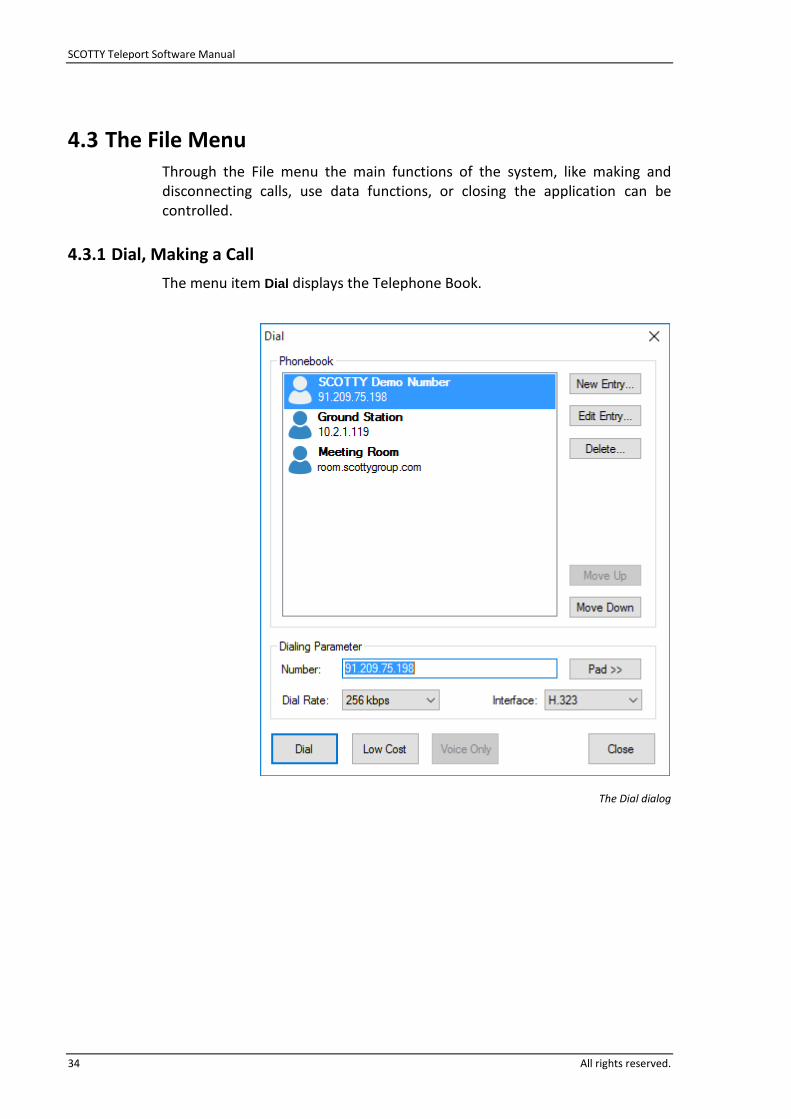
The menu item Dial displays the Telephone Book.
The Dial dialog

SCOTTY Teleport Software Manual
All rights reserved. 35
The user can choose the desired remote station from the list or alternatively enter the phone number directly into the edit field Number. When selecting an entry from the phone book the number is displayed inside this edit field as well. For details about the phone number format, see chapter 4.3.3.
A click on Dial or a double-click on the remote station name in the Telephone Book closes the Dialog and begins the dialing to the selected remote station. A dialog is displayed while the dialing is taking place. If the Cancel button is pressed, the dialing process is aborted.
Low Cost begins a videoconference to the selected remote station with a reduced bandwidth, reducing the running costs of a videoconference connection. The bandwidth is defined under Options | Dialing…
Voice Only places a voice call, if supported by the current network type.
Dial Rate enables the user to select the dial rate to be used. The choices available depend on the selected interface.
Interface selects the interface to be used for this call. The available choices are dependent on the present system configuration.
When using an on-demand network access, make sure the SCOTTY system is connected to the network before placing the call.
For reliable video calls, choose a rate low enough to allow variance in the network throughput. When connecting through a bandwidth limited network, choose a dial rate below the net data rate of the network to allow for IP overhead.
Pad >> brings up an additional dial pad used to directly enter a phone number or IP-address without using the keyboard. This dial pad can be hidden by clicking Pad <<.
New Entry… opens a dialog to create a new Telephone Book entry. See next chapter for details.
Edit Entry… opens a dialog to alter the currently selected entry.
Delete… is used to delete the currently selected entry. If this operation is confirmed by a Yes then the selection is deleted.
Move up repositions the entry one step up in the column.
Move down repositions the entry one step down in the column.
Close closes the dialog.

SCOTTY Teleport Software Manual
36 All rights reserved.
4.3.2 Creating or Modifying a Telephone Book Entry
The dialing parameters for a remote station can be entered by pressing the button New Entry or Edit Entry in the Dial dialog.
The Edit Entry dialog
Name defines the name of the remote station which appears in the Telephone Book. If the network supports "caller’s number" the name of the remote station is also displayed on an incoming call.
The telephone number of the remote station is entered in the Number field. The appropriate format is described in the next chapter.
Interface describes the type of network interface used. Depending on the hardware configuration, various settings can be chosen. Usually the field is left on "Automatic" – meaning the default interface set under Options Dialing is used, or another available interface identified by the phone number entered.
Dial Rate defines the used data rate for the call. According to the set interface, several rates can be selected. Usually the field is left on "Default"- meaning the default value of the interface being used is taken. The default values for each available interface can be set under Options Dialing.
OK confirms the entry and closes the dialog.
Cancel aborts the changes and closes the dialog.
If a Telephone Book entry is set to a value which is not supported by the currently used hardware, it is indicated "Not Supported" and the default values will be automatically used.

SCOTTY Teleport Software Manual
All rights reserved. 37
4.3.3 Format for Entering the Telephone Number
The Telephone Book supports different number formats to enter the phone number of a videoconference partner:
If the videoconferencing partner can be reached by name, it can be used as a telephone number in the telephone book, e.g. demograz.scottygroup.com.
The direct way to establish a connection is by entering the IP address of the videoconferencing partner. Tip: The system’s current IP address is shown under Help | About Teleporter. For IPv6 addresses, enclose the address with square brackets.
If a gatekeeper is configured in the Configuration Utility, remote systems can be reached by entering their registered name or number. Usually, multi-point video conferences are also registered on a gatekeeper and can be dialed with their conference ID.
Summarizing, the following formats are available for phone numbers:
Hostname: <DNS name> e.g.: demograz.scottygroup.com
Computer name inside a domain or workgroup: <computer name> e.g.: SI2438010
IPv4 address: <IPv4-address> e.g.: 91.209.75.198
IPv6 address: [<IPv6-address>] e.g.: [2001:67c:511c::548]
If the local system is registered on a gatekeeper, additional formats are available (details depending on gatekeeper configuration):
Number or conference ID registered on the gatekeeper: <ID> e.g.: 6039
Name of a remote system registered to the gatekeeper: <name> e.g.: Room28
To specify a gatekeeper for a call, add its name or address to the phone number, separated by an at sign: <phone number>@<gatekeeper> e.g.: [email protected]
A custom IP port number for the call setup may be added to all phone number formats, separated by a colon: <phone number>:<port>
e.g.: [email protected]:8200
SCOTTY Teleport Software Manual
38 All rights reserved.
4.3.4 Disconnect, Terminating a Call
This terminates an ongoing call and the system returns to the standby mode.
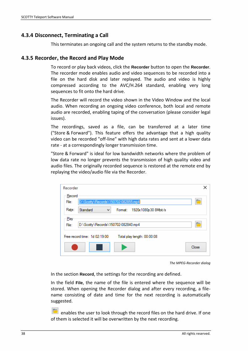
4.3.5 Recorder, the Record and Play Mode
To record or play back videos, click the Recorder button to open the Recorder. The recorder mode enables audio and video sequences to be recorded into a file on the hard disk and later replayed. The audio and video is highly compressed according to the AVC/H.264 standard, enabling very long sequences to fit onto the hard drive.
The Recorder will record the video shown in the Video Window and the local audio. When recording an ongoing video conference, both local and remote audio are recorded, enabling taping of the conversation (please consider legal issues).
The recordings, saved as a file, can be transferred at a later time ("Store & Forward"). This feature offers the advantage that a high quality video can be recorded "off-line" with high data rates and sent at a lower data rate - at a correspondingly longer transmission time.
"Store & Forward" is ideal for low bandwidth networks where the problem of low data rate no longer prevents the transmission of high quality video and audio files. The originally recorded sequence is restored at the remote end by replaying the video/audio file via the Recorder.
The MPEG-Recorder dialog
In the section Record, the settings for the recording are defined.
In the field File, the name of the file is entered where the sequence will be stored. When opening the Recorder dialog and after every recording, a file-name consisting of date and time for the next recording is automatically suggested.
enables the user to look through the record files on the hard drive. If one of them is selected it will be overwritten by the next recording.

SCOTTY Teleport Software Manual
All rights reserved. 39
Rate chooses the data rate and resolution at which the recording takes place:
Standard: The highest available quality is used. This setting is advisable for standard recordings where the file size of the video files is not critical.
Medium: The system use the resolution of the current video input and chooses a matching data rate to achieve a medium recording quality. This setting is ideal for Store & Forward applications as it allows quick transfer of the video files thus preserving the full resolution of the video source.
Low: A low resolution and data rate is selected, allowing very long duration recordings.
Format displays the estimated video format and data rate depending on the current settings.
The video format in the recorded file is automatically adapted to match the actual aspect ratio of the recorded signal and will use progressive scan.
In the section Play, the file to be played is selected. After every recording the field is set to the last recorded file for immediate play back.
With stored video-files can be selected to play back.
Free record time displays the possible record time which is calculated by the indicated data rate and the free space available on the disk.
Total play length shows the play time of the selected video file in the Play field.
Record starts the record process.
Stop stops the recording or playback.
Play plays the file selected in the Play field. For advanced playback options, open the file with the system player.
Close closes the dialog.
The folder containing the recordings can be opened using View | Recorded File, e.g. to view a video with the system player or to copy, delete and rename the files. The default location of the recorded files can be defined in Options | Directories.
The standard rate setting can be set in the Configuration Utility, tab Streaming, and form the upper limit for recordings in the other rates. The standard rate is also used for streaming and the overlay inside the Video Window when no recording takes place. During a recording, streaming and overlay share the video resolution and data rate used by the recorder.
SCOTTY Teleport Software Manual
40 All rights reserved.
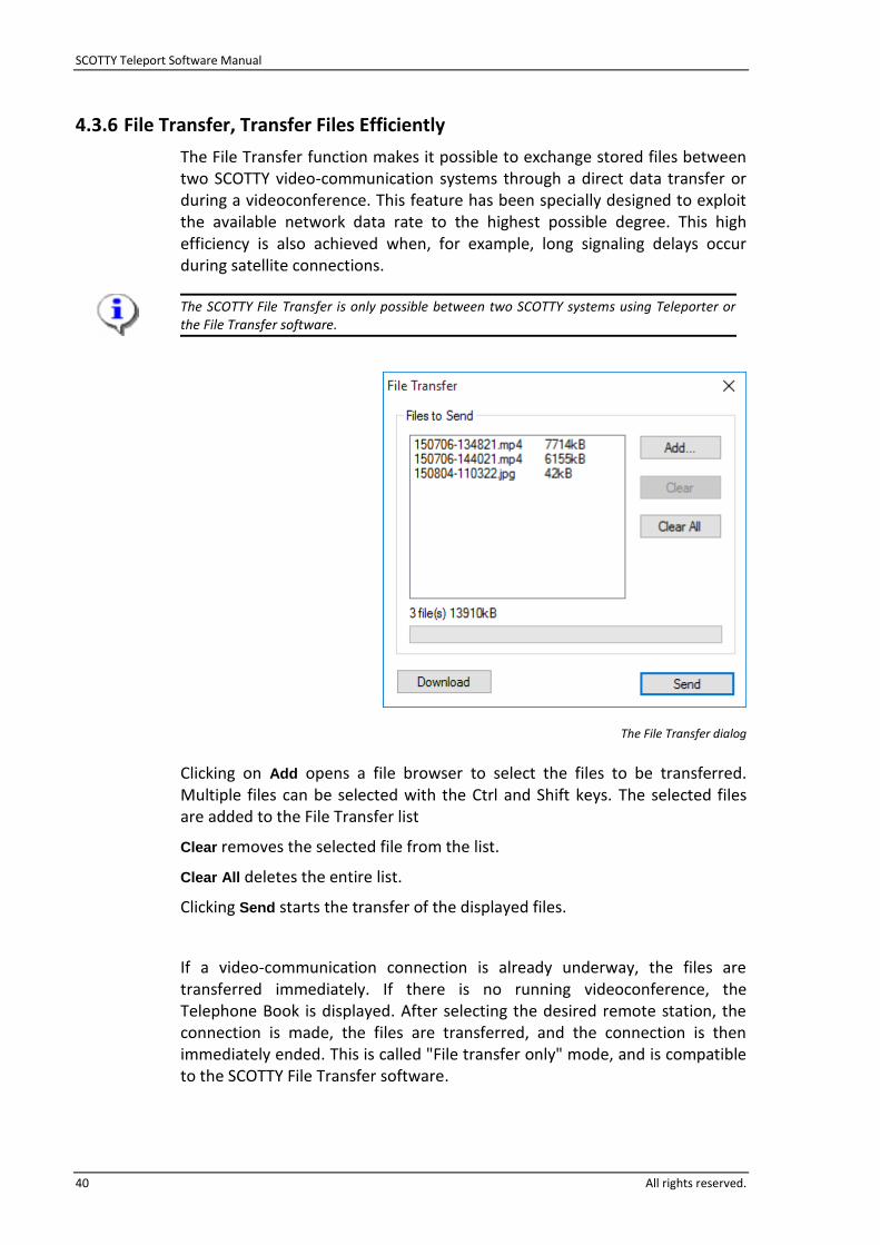
4.3.6 File Transfer, Transfer Files Efficiently
The File Transfer function makes it possible to exchange stored files between two SCOTTY video-communication systems through a direct data transfer or during a videoconference. This feature has been specially designed to exploit the available network data rate to the highest possible degree. This high efficiency is also achieved when, for example, long signaling delays occur during satellite connections.
The SCOTTY File Transfer is only possible between two SCOTTY systems using Teleporter or the File Transfer software.
The File Transfer dialog
Clicking on Add opens a file browser to select the files to be transferred. Multiple files can be selected with the Ctrl and Shift keys. The selected files are added to the File Transfer list
Clear removes the selected file from the list.
Clear All deletes the entire list.
Clicking Send starts the transfer of the displayed files.
If a video-communication connection is already underway, the files are transferred immediately. If there is no running videoconference, the Telephone Book is displayed. After selecting the desired remote station, the connection is made, the files are transferred, and the connection is then immediately ended. This is called "File transfer only" mode, and is compatible to the SCOTTY File Transfer software.

SCOTTY Teleport Software Manual
All rights reserved. 41
When a file transfer is started, the SCOTTY remote system displays the Received Files dialog (see chapter 4.4.8).
A running transfer can be discontinued through Abort.
Download will download files from a File Exchange Server (optional).
The name of the file being transferred, the number of bytes already transferred, as well as the actual data rate are continually displayed. A bar gives a visual representation of the progress of the transfer.
The File Transfer can be configured under Options | Data.
If the connection is suddenly broken when transferring a file with the SCOTTY File Transfer system, it is not necessary to retransmit the entire file. The SCOTTY File Transfer will finish the transfer from the point of disconnection without any data loss.
When adding files to the transfer list they are automatically copied into a separate outgoing folder on the disk. Therefore, individual files can be assembled - for example from several USB sticks. The folder can be configured under Options | Directories.

SCOTTY Teleport Software Manual
42 All rights reserved.
4.3.7 Snap & Send, Sending Still Images
The Snap & Send feature enables users to easily transfer a high resolution still image of the currently selected video source to the far end. The Snapshots are copied into the clipboard, stored in the Records folder as JPG files and then transferred to the remote party using the SCOTTY File Transfer feature. Snap & Send files are prioritized during an ongoing File Transfer.
Snap & Send can be used during an ongoing conference as well as in idle mode. When using in idle mode, the Phonebook is displayed to enter the dial parameters of the remote party or, if Auto dial under Options | Data is activated, the currently active dial parameters are used. If the connection had been established through Snap & Send, it will be automatically disconnected after the transfer is complete.
The snapshot is automatically displayed on the receiving side if Auto show
incoming images is activated.
For more details about snapshots, see chapter 4.3.8; details about the data transfer can be found in the chapter 4.3.6.
4.3.8 Snapshot, Taking a Still Picture
This function takes a still picture from the video source currently appearing in the Video Window (for example, a local camera or the received video). Snapshots are stored automatically as JPG files into the Records folder. Furthermore, the picture is copied into the Windows clipboard and is available to other applications.
The location of the Records folder can be defined in Options | Directories. The folder can be opened using View | Recorded Files.
If a position information source like an external GPS unit is configured in the SCOTTY Configuration Utility, the position, date and time information is stored into to JPG file using an EXIF header. This makes it possible to track the position where a snapshot was taken.
4.3.9 Exit, Ending the Program
This function shuts down the SCOTTY Teleporter.

SCOTTY Teleport Software Manual
All rights reserved. 43
4.4 The View Menu This menu enables activation of the Video Window and several dialogs for advanced control of the system.
The settings are only "permanently" saved when they are saved manually with Options | Save or when the Save on Exit setting under Options | Preferences is activated. Otherwise the modi-fications are lost upon ending Teleport.
4.4.1 Video Window, Manipulating the Video Window
The Video Window displays the local or received video. It can be activated or deactivated through the menu View | Video Window.
The size of the window can be adapted to the current situation by clicking on an edge or corner of the window and dragging it to the desired size.
A double-click on the video will expand the video to full screen.
If the Maximize button is clicked, the Video Window expands. With the aid of the Minimize button, the Video Window can be "set aside"; by clicking the appropriate button in the Windows task bar, the Video Window reappears.
A single click to the video will toggle between the Video Window and the Teleport toolbar including open dialogs. This behavior is especially useful when the video is displayed in full screen: A click inside the video window brings the Teleport toolbar above the video, to e.g. change the volume, another click hides the toolbar to continue an undisturbed video conference.
4.4.2 Fullscreen Video Window, Activating Full Screen
By clicking on the menu item View | Video Window the Video Window toggles between full screen and normal mode.
Using this menu item is equivalent to double-clicking inside the Video Window.

SCOTTY Teleport Software Manual
44 All rights reserved.
4.4.3 Camera Control, Controlling Local and Far End Cameras
The camera control dialog is used to remote control a local as well as a far end camera. It can be shown through the menu View | Camera Control.
The Camera Control dialog controlling a local camera
The dialog can be switched between local and far end camera control with the Local and Remote tabs.
When controlling a local camera, the availability of the functions depends on the current remote-controllable camera. The local camera can be configured using the SCOTTY Configuration Utility.
If more than one remote-controllable camera is configured the system automatically selects the camera in use, depending on the video settings in the Audio & Video Controls dialog. The camera under control is shown in the Controlled Camera field.

SCOTTY Teleport Software Manual
All rights reserved. 45
Pressing the Remote tab switches to far end camera control. This feature makes it possible to control the videoconferencing partner’s camera and video input. It is only possible during a video conference call and if supported by the remote side.
The video source that the remote side transmits to the local system can be selected with Video Source. Depending on the capabilities of this camera, the camera control buttons are enabled or disabled. The source Current allows control of the remote camera currently in use.
For both local and remote camera, the Pan/Tilt/Zoom and Focus sections control the zoom function and the panning and tilting of the camera head.
Left and Right pan the camera.
Up and Down tilt the camera.
Zoom In and Zoom out zoom the lens of the camera.
Focus Near and Focus Far set the focus of the camera.
Autofocus activates the automatic focus.
Preset 1 to 8 recalls a previously saved position.
Clicking Save, followed by one of the Preset buttons, stores the current camera position as preset.
The far end camera control functionality depends on the implementation of the remote system and might vary from using the local camera.
During a call, the remote side can control local cameras and switch the local video input. The toolbar notifies when the local video gets switched by de-selecting the current audio & video preset. To prevent the remote side to control the local video, activate Reject local camera
control in Options | Data.
SCOTTY Teleport Software Manual
46 All rights reserved.
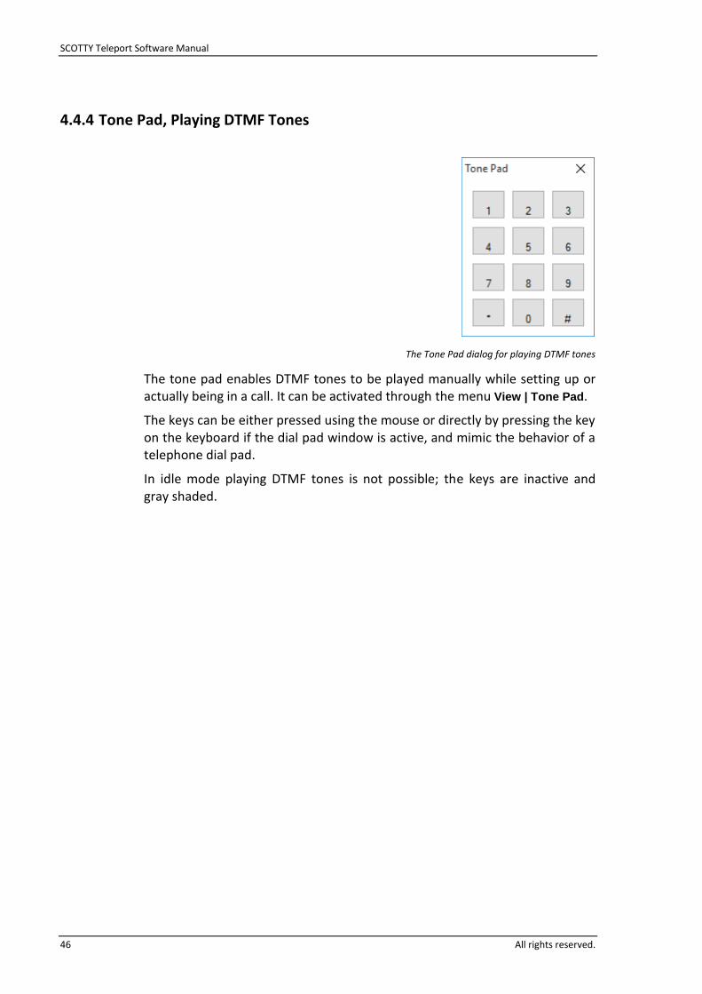
4.4.4 Tone Pad, Playing DTMF Tones
The Tone Pad dialog for playing DTMF tones
The tone pad enables DTMF tones to be played manually while setting up or actually being in a call. It can be activated through the menu View | Tone Pad.
The keys can be either pressed using the mouse or directly by pressing the key on the keyboard if the dial pad window is active, and mimic the behavior of a telephone dial pad.
In idle mode playing DTMF tones is not possible; the keys are inactive and gray shaded.

SCOTTY Teleport Software Manual
All rights reserved. 47
4.4.5 Audio & Video Controls
The dialog Audio & Video Controls enables the flexible setting of the audio and video parameters. The user can decide which video source should be shown. Moreover, the corresponding audio preset (defined by the user in Options | Audio), the location of the picture in picture, and the speaker volume is set.
The Audio & Video Controls dialog
It is possible to define three individual presets with the tabs at the top of the dialog and save each of them with a different descriptive name. The name is changed by clicking on the name of an entry with the right mouse button and then entering the new name. Usually the first setting is reserved for the live camera, the second and third for external video sources. These presets can be easily called up through the Preset A, B and C buttons in the Toolbar. To make the function of a preset immediately apparent, the name of the preset appears as a "Tool Tip" when the mouse cursor is moved onto the button.
In Video Select, the independent selection of various video sources through a video switch matrix can be made.
Following video sources are available:
video received from the remote system (Receive),
one of the local video inputs (e.g. DVI 1, CVBS),
Video transmitted to the remote system (Transmit).

SCOTTY Teleport Software Manual
48 All rights reserved.
These signals can be either:
transmitted to the remote system (Transmit),
displayed in the Video Window (Screen),
displayed on equipment connected to the video outputs (Output).
Which combinations are possible depends on the hardware configuration of your system.
In Audio Levels a user defined audio preset can be chosen (set under Options | Audio).
Pic in Pic activates and controls the location of the "picture in picture", a small window displaying the transmitted video inserted into the received video. This function is also available under View | Pic in Pic.
Volume adjusts the volume of the audio outputs. The setting of the volume is also possible through the Volume up and Volume down buttons on the toolbar.
When doing a professional videoconference, the control matrix not only enables the easy manipulation of the video and audio inputs and outputs, it also lets the user define presets for special situations. A typical example is a videoconference between two large audiences. In this case it is often required to switch between the internal camera and the internal microphone and the external camera and the external microphone. By arranging a preset for every situation, switching to a specific setup is made easy with only one mouse click!
Example: The illustration at the beginning of this section depicts an example of the Controls function in action. The preset labeled "Input 1" is active. The video camera connected to “DVI 1” is transmitted to the remote station; the received video signal is displayed on the screen and outputted on the video output. Furthermore, because the "picture in picture" function is enabled, the video being transmitted to the remote station is inserted in the lower right of the "Receive" video. The Audio Levels of the preset "Default" are set.
The presets are only "permanently" saved when they are saved manually with Options | Save or when the Save on Exit setting under Options | Preferences is activated. Otherwise the modi-fications are lost upon ending Teleporter.
.

SCOTTY Teleport Software Manual
All rights reserved. 49
4.4.6 Pic In Pic, Setting the Picture in Picture view
In the Pic in Pic menu settings for the "picture in picture", a small window displaying the transmitted video inserted into the received video can be activated.
The entries Disabled, Upper Left, Upper Right, Lower Left and Lower Right correspond to the Pic in Pic settings under View | Controls.
The size of the Pic in Pic window can be controlled with Small, Medium and Large.
4.4.7 Toolbars, Manipulating the Toolbars
The menu View | Toolbars is used to manipulate the toolbars.
Standard enables the toolbar. The available functions are explained in chapter 4.2.
The toolbar can be dragged out of the main window and repositioned individually by clicking between two buttons and dragging the toolbar. To dock the toolbar, drop it on the main window.
Status Bar alters the display of the status bar in the main window. The status bar displays contextual help, the currently running system operation, and other helpful information.

SCOTTY Teleport Software Manual
50 All rights reserved.
4.4.8 Received Files, Listing the Received Files
This menu opens the Received Files dialog.
The dialog is automatically displayed when a file is received by the SCOTTY File Transfer function (see chapter 4.3.6).
The Received Files dialog during a transfer
The Received Files dialog displays a list of files already received as well as the transfer progress of the currently received file. This is also displayed by a bar.
Clear List deletes the list, but not the received files.
Explorer… starts Windows Explorer and opens the Incoming folder. It is then very easily to copy, move, or open received files.
Close closes the dialog.
Abort cuts off the currently active transfer of a file.
If the SCOTTY Teleporter software is active but unattended and the Automatic Pickup feature is activated (see chapter 4.5.6), the system can connect and receive file transfers automatically. After disconnection the dialog Received Files remains visible. When the system is re-attended, the Received Files displays which files have been received.
The location of the received files can be defined in Options | Directories.
SCOTTY Teleport Software Manual
All rights reserved. 51
4.4.9 Recorded Files, View recorded Files
This function opens the Windows Explorer, showing the Records folder which holds the recorded videos and snapshots.
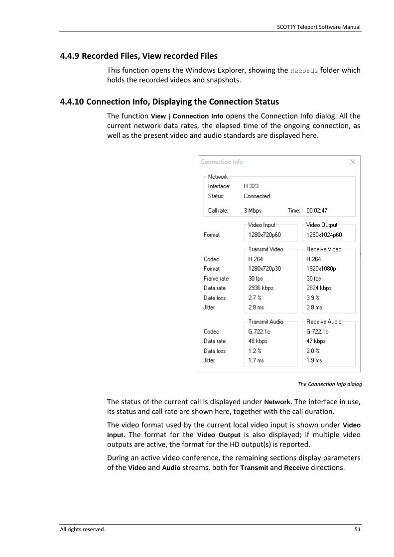
4.4.10 Connection Info, Displaying the Connection Status
The function View | Connection Info opens the Connection Info dialog. All the current network data rates, the elapsed time of the ongoing connection, as well as the present video and audio standards are displayed here.
The Connection Info dialog
The status of the current call is displayed under Network. The interface in use, its status and call rate are shown here, together with the call duration.
The video format used by the current local video input is shown under Video
Input. The format for the Video Output is also displayed; if multiple video outputs are active, the format for the HD output(s) is reported.
During an active video conference, the remaining sections display parameters of the Video and Audio streams, both for Transmit and Receive directions.

SCOTTY Teleport Software Manual
52 All rights reserved.
4.5 The Options Menu Defining the Teleport configuration is done through the Options menu.
The settings under Dialing, Transmit, Audio and Data are only "permanently" saved when they are saved manually with Options | Save or when the Save on Exit setting under Options |
Preferences is activated. Otherwise the modifications are lost upon ending Teleporter.
4.5.1 Dialing, Setting the Dialing Parameters
In the Dialing Configuration dialog, the interface and the standard values for the dialing process can be set.
The Dialing Configuration dialog
Default Interface defines the type of network interface used by default. This setting is used by the Dial dialog when the interface is set to "Automatic".
For each interface the standard values for the dialing process can be set in the Default Values section. These are active when the corresponding interface is used for dialing, unless overridden by manual entries in the Telephone Book.
These values are individually saved for each interface. All interface-specific settings should be defined in this dialog so that the Telephone Book entries remain as universal as possible (interfaces set to "Automatic" and all settings set to "Default"). This ensures that the Telephone Book entries can be used regardless of the currently used network type.

SCOTTY Teleport Software Manual
All rights reserved. 53
4.5.2 Audio, Setting the Audio Levels
The Audio Configuration dialog enables the setting of the audio levels of the audio sources and audio outputs.
The Audio Configuration dialog
By being able to define three groups of settings with the three tabs at the top of the dialog, frequently used configurations can be quickly activated. A meaningful name can be entered for each of the three presets by clicking on the name field with the right mouse button (e.g. "Headset" is clicked and the desired name is inputted). These settings are available under View | Audio &
Video Controls.
In section Input Mixer, the input levels of the audio sources can be regulated. Activating Mute disables an input. All enabled inputs are mixed together for recording and transmitting; a level meter displays the volume of the mixed signal.
If enabled, the AuxIn audio signal is not only transmitted to the remote side during a videoconference, but also mixed to the audio outputs. It is intended for the connection of external playback devices which can be heard both by the local and remote audience.

SCOTTY Teleport Software Manual
54 All rights reserved.
The section Output Mixer controls the base levels of the audio outputs. Activating Mute disables an output. The master output level itself is controlled by the "Speaker Volume" in the Audio & Video Controls window. A level meter displays the audio level that is fed into the Output Mixer.
AuxOut contains both the audio from the input and output mixer, so that both the received and the transmitted audio can be monitored or recorded by a device connected to the auxiliary output. Its volume is not affected by the master output level.
Audio improvements are controllable in the section Audio Processing.
Auto Gain (optional) activates the automatic volume adjustment of the microphone audio inputs.
The button Echo Removal (optional) activates the echo canceller which prevents feedback from the audio outputs to the audio sources. The auxiliary audio input and output are not affected by the echo canceller.
The section Soundcard Input is used to enable and disable Windows sound on the audio outputs.
Audio Test enabled testing the audio equipment. When the Audio Configuration dialog is closed, the test settings are disabled automatically.
Enabling Loop loops the audio inputs to the audio outputs. Caution: This will usually generate very loud feedback!
With Play Test Tone a test signal is mixed to the input and output mixer.
Please note that the available choices inside this dialog depend on the hardware and software configuration of the system.
The level meters and the test tone feature greatly simplify audio setup. To level the audio sources input by input, simply activate Mute for all other inputs, and then adjust the input level using the level meter. The audio outputs can easily be checked by activating the test tone.

SCOTTY Teleport Software Manual
All rights reserved. 55
4.5.3 Transmit, Setting Audio and Video Parameters
The dialog Transmit Configuration allows to control the video and audio optimization preferences used during a video conference call.
The Transmit Configuration dialog
The section Video Transmit Optimization is used to configure how the transmitted video shall be optimized between Motion and Sharpness. Moving the slider to Motion will change the video to fluid motion with high frame rate, the Sharpness side of the scale creates high resolution video with correspondingly lower frame rate; a central position will balance between these two.
This optimization can be individually configured for each video input. This way, for example, a room camera can be set to Motion whereas Sharpness can be used for a surveillance camera.
Changing the setting of the transmitted video source will immediately change the video encoder parameters. To indicate the current input, the names of the inputs not active at the moment are greyed out.
Under Audio Transmit Optimization the optimization of the audio encoding format can be controlled. Moving the slider towards Bandwidth will activate an audio standard with low bandwidth usage, sliding toward Quality will activate a high quality audio transmission with accordingly higher bandwidth demand. Changing this setting during a call will immediately change the audio encoder parameters.
During a call, the system uses these settings together with other parameters to decide which video resolution, frame rate and audio codec shall be used for transmission. The resulting parameters are visible in the Connection Info dialog.

SCOTTY Teleport Software Manual
56 All rights reserved.
4.5.4 Data, Adjusting the Data Channel Parameters
This dialog makes the configuration of the data channel parameters possible.
The Data Configuration dialog
File Transfer and Snap & Send controls the SCOTTY specific File Transfer function.
Enable enables the SCOTTY specific File Transfer function.
In the section In-Call Bandwidth Mode, the distribution of video, audio and data during a video conference call can be adjusted. This setting only applies during a file transfer; afterwards the original bandwidth distribution (video/audio) is restored.
Activating Auto Dial on Snap & Send will automatically dial up the current phonebook settings when not in a call and using the Snap & Send feature. This way, making and sending a snapshot to a remote station with just one click is possible.
If Auto Show incoming Images is activated, on reception of a snapshot file via File Transfer, the image file is opened automatically with the associated Windows program. This setting is especially useful on a station receiving snapshots over the Snap & Send feature.
Reject incoming files prevents files from a remote station to be received.
Enable File Exchange Server enables the optional File Exchange Server. Please contact your SCOTTY representative for further details.
If the checkbox Use data compression is selected, all files get compressed for transmission and decompressed by the SCOTTY system on the remote site automatically. By selecting Overwrite without query existing files in the incoming directory of the partner station with the same filename get

SCOTTY Teleport Software Manual
All rights reserved. 57
overwritten without confirmation by the user. When enabling Log activities to
journal file, every activity of the file transfer (no matter if successful or not) is logged to a journal file. The journal file can be viewed by clicking on the button View… and it can be emptied by clicking on the button Clear…
Far End Camera Control controls the Far End Camera Control functions.
Enable FECC enables the Far End Camera Control function.
Reject local camera control prevents the remote site from controlling the local system, but does not prevent controlling the remote system.
In the section Share Desktop, Enable H.239, H.239 Dual Video Channel (optional) can be enabled.

SCOTTY Teleport Software Manual
58 All rights reserved.
4.5.5 Directories, Setting the SCOTTY Directory Structure
With this dialog the directory structure used by the SCOTTY Teleporter can be controlled.
The Directories dialog
Phone Book defines the location of the phone book.
By activating Make Phonebook "read only", the phone book cannot be modified by the user.
If Use Phone Book as default path is activated, the folders for recordings, snapshots and file transfer are automatically created in the same directory as specified by the phone book. Otherwise the user can manually specify which directories should be used:
Incoming specifies where files received by the file transfer feature are stored.
The folder Outgoing is used when preparing files for file transfer.
Records holds recorded video files and snapshots.
Save closes the dialog and saves the current settings.
Cancel closes the dialog without saving the settings.
The Telephone Book is saved in a text-file. Therefore, it can be edited with an external text editor; copying a different system's Telephone Book into the system is possible.

SCOTTY Teleport Software Manual
All rights reserved. 59
4.5.6 Preferences, Setting the System Parameters
This dialog enables the user to manipulate some general settings as well as to set the system's reaction to an incoming call.
The Preferences dialog
Always on top prevents the windows of other applications to cover the SCOTTY Teleport windows.
Hide options menu removes the menu option Options from the menu bar to prevent unintentional changes to these settings. Through the shortcut Ctrl+P the Preferences dialog can be displayed and used to re-enable Options.
If Current Settings is activated, the current audio, transmit, dialing and data settings and presets are saved when ending the Teleporter.
Window and toolbar positions configures that the most recent window, dialog and toolbar positions are saved on Teleporter exit.
Automatic pickup defines the behavior when no user input follows an incoming call. When the system receives a call, a dialog is displayed enabling the user to take or reject the call. When Automatic pickup is enabled the call is automatically taken after a short timeout.
Screensaver selects if the system’s screensaver is disabled or enabled during a video conference.
Save saves the chosen settings immediately.
Cancel cancels the changes and closes the dialog.

SCOTTY Teleport Software Manual
60 All rights reserved.
4.5.7 File Exchange
The File Exchange menu is available only if this option is installed in the system. Please contact your SCOTTY representative for further details.
4.5.8 Save, Saving the Current Settings
This dialog makes it possible to save the Teleporter settings manually. Alternately, in Options | Preferences the system can be set to automatically save the configurations when ending the program.
The Save dialog
By clicking Controls and options settings, the current audio, transfer, dialing and data settings and presets can be saved. These settings are recalled at every restart of the SCOTTY Teleport software.
Window and toolbar positions enables the window, dialog and toolbar positions to be saved. These settings are also recalled at every restart of the SCOTTY Teleporter software.
Cancel closes the dialog without saving the settings.
OK closes the dialog and saves the current settings.
System recovery procedures will reset all user defined settings. See chapter 5 for details.

SCOTTY Teleport Software Manual
All rights reserved. 61
4.5.9 Factory Defaults, Restoring the Factory Defaults
This function opens the dialog to restore the factory defaults.
The Restore Factory Defaults dialog
When confirmed with Yes, the user's settings under View | Audio & Video
Controls, all settings under the Options menu, and the window, dialog and toolbar positions are restored to the original factory values.
Restore Factory Defaults permanently overwrites all current settings! The settings in the dialogs should be checked afterwards.

SCOTTY Teleport Software Manual
62 All rights reserved.
4.6 The Help Menu This menu is used to display help information.
To support troubleshooting, the help menu is also available when a problem is displayed during Teleport startup.
4.6.1 Help Topics, the SCOTTY Help System
Opens the SCOTTY Teleport on-disk help, i.e. this manual, with a built-in viewer application.
To navigate through the document, use the Bookmarks on the left side or click on references in the table of contents or directly in the text.
read continuously through the manual
view in page mode
turn pages
print the manual. Please note that the manual is optimized for double-sided print.
4.6.2 Open Manual, View System Documentation
This menu item enables direct access to the pre-installed documentation, like software and hardware manuals and quick references.
After selection of the desired document it is opened in the built-in document viewer. See previous chapter for details on how to navigate or print with the viewer application.
The documentation files are directly available through the Windows Start Menu with Start | All Apps | Scotty | Manuals.
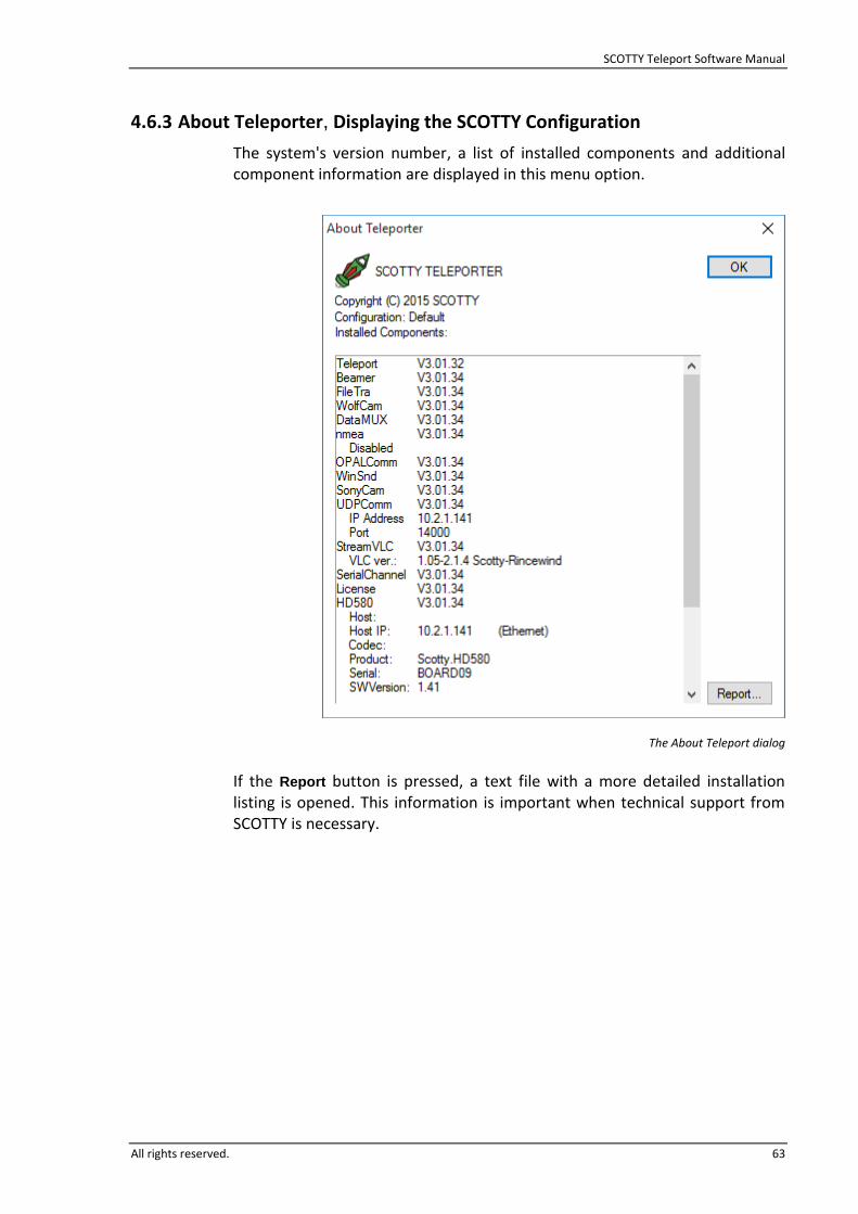
SCOTTY Teleport Software Manual
All rights reserved. 63
4.6.3 About Teleporter, Displaying the SCOTTY Configuration
The system's version number, a list of installed components and additional component information are displayed in this menu option.
The About Teleport dialog
If the Report button is pressed, a text file with a more detailed installation listing is opened. This information is important when technical support from SCOTTY is necessary.

SCOTTY Teleport Software Manual
64 All rights reserved.
This page intentionally left blank.

SCOTTY Teleport Software Manual
All rights reserved. 65
5 System Recover
SCOTTY systems optionally feature an integrated system recovery to recover the system to its delivery state. If application files are accidentally destroyed or the operating system is malfunctioning, the system can be put into a working state again by restoring the delivery state.
SCOTTY systems use up to three hard-disk partitions. The system partition C: contains the operating system and installed applications. The data partition D:, if available, is used to save data, videos and the phonebook. An additional hidden recovery partition is used by the SCOTTY System Recover mechanism. Restoring the systems delivery state can be done directly on the device without any additional tools or media, even if the Windows operating system cannot be started anymore. If on-disk system recovery is not possible due to a destroyed recovery partition or hard-disk, the system can also be restored by using an external recovery USB-stick. Please note that DVD’s are also possible instead of a USB-stick, but might require an external DVD drive connected to the SCOTTY system.
In summary the SCOTTY system recover has the following features:
Access control for all recovery functions using passwords.
On-disk system recover without additional recovery media.
System recover from bootable recovery stick.
Creation of new recovery sticks.
Creation of a user defined hard disk image, a so-called “admin image”. Apart from the delivery state, a personalized system state can be saved and restored at any time.
Creation of full system backups to external media. A personalized system state, including the data partition, can be stored onto external media and restored at any time using the recovery software.
Displaying of additional system information.

SCOTTY Teleport Software Manual
66 All rights reserved.
5.1 Restoring the System
Reboot the computer.
The boot manager screen is displayed for several seconds during the startup.
Boot manager
Choose Recover V3 using the Arrow-down Key and press Return.
After the recovery software has started use password “restore“ to proceed.
The main menu of the recovery software is displayed. Depending on the system configuration some menu items might not be available.
Recovery software: Main menu
SCOTTY Teleport Software Manual
All rights reserved. 67
The recovery software can be left with Exit. The menu item Display system information can be used to display information about the hardware and software configuration of the stored delivery state.
Choose one of the following functions:
Restore C: with factory image:
The system partition C: will be restored to delivery state.
Restore C: and D: with factory image:
The system partition C: and the data partition D: will be restored to delivery state.
Restore C: with admin image:
Only available if an admin image exists: The system partition C: will be restored to the user defined state.
Restore C: with admin image, D: with factory image:
Only available if an admin image exists: The system partition C: will be restored to the user defined state and the data partition D: will be restored to delivery state.
Confirm the upcoming warning with Yes.
Reboot computer after restoring.
Warning: When restoring a partition C: or D: to delivery state all data stored on the
particular partition after delivery will be lost.

SCOTTY Teleport Software Manual
68 All rights reserved.
5.2 Restoring the System using a Recovery Stick Restoring the system from a recovery stick is only necessary if the recover partition is destroyed or not available.
Use only a recover stick with the correct system serial number.
Plug in the recovery USB stick.
Reboot the computer.
Activate the USB stick as boot device:
o On most SCOTTY systems, enter BIOS setup by pressing DEL at the beginning of the boot process. Select menu Boot, entry Boot Option #1 and choose the USB stick. Switch to the menu Save & Exit and choose Save Changes and Exit.
o On other systems, the procedure is similar but might vary in details. Some systems use F2, F10 or F11 to open the BIOS setup or a boot menu; some feature a setup button which can be pressed when the system is shut down.
The computer is now booting from the recover stick.
The main menu of the recover stick software is displayed.
Recover stick software: Main menu
The recovery software can be left with Exit. The menu item Display system information can be used to display information about the hardware and software configuration of the stored delivery state.

SCOTTY Teleport Software Manual
All rights reserved. 69
Choose one of the following functions:
Restore whole HDD with factory images:
The whole hard disk will be reset to delivery state.
Restore C: with factory Image:
The system partition C: will be restored to delivery state. This function should be used only if the remaining partitions are functional.
Confirm the upcoming warning with Yes.
Reboot computer after restoring.
Warning: When restoring the whole hard disk to delivery state all data stored after
delivery onto C: or D: as well as an optional admin image are lost!
5.3 Creation of a User defined Hard Disk Image As SCOTTY offers the possibility to create a user defined image of the system partition, a personalized system state can be saved and restored at any time. This user defined image, a so-called “admin image”, is saved onto the hidden recovery partition together with the factory image containing the delivery state. Thus, the restoration of the delivery state remains possible, even after creation of an admin image.
An admin image can be created after a possible change to the systems state or after installation of additional software. The saved system state can then be restored at any time without additional tools. Without an admin image, only the systems delivery state not containing any custom changes can be restored.
Creation of a user defined hard disk image:
Reboot the computer.
The boot manager screen is displayed for several seconds during the startup (see figure: Boot manager).
Choose Recover V3 using the Arrow-down Key and press Return.
After recovery software has started use password “restore“ to proceed.
The main menu of the recovery software is displayed (see figure Recovery software: Main menu).
Choose Create admin image.
Enter password for creating an admin image and press the button Create.
After creation of the admin image the system returns to the main menu.
SCOTTY Teleport Software Manual
70 All rights reserved.
To restore a user defined hard disk image please follow the instructions in chapter 5.1.
When creating a new recover stick, the current admin image is automatically copied to the stick. When restoring the full hard disk from this recover stick, the admin image is copied back to the hard disk and is available from the recovery software’s main menu.
5.4 Creation of New Recover Stick A new recovery stick can be created at any time using the SCOTTY recovery software. This is useful, if the original recover stick is lost or an admin image was created and an updated recover stick should be created.
Creation of new recover stick:
Reboot the computer.
The boot manager screen is displayed for several seconds during the startup (see figure: Boot manager).
Choose Recover V3 using the Arrow-down Key and press Return.
After recovery software has started use password “restore“ to proceed.
The main menu of the recovery software is displayed (see figure Recovery software: Main menu).
Connect the USB recovery stick to the system.
Warning: When creating a USB recovery stick, the previous content of the stick will be
deleted! The stick must have adequate memory capacity.
Choose Create recover media and select one of the available USB media.
Press button Create media.
Follow the instructions on the screen.

SCOTTY Teleport Software Manual
All rights reserved. 71
5.5 Full System Backups A “full system backup” contains the current state of the entire system including all data of the data partition. A system backup can be stored to an external memory device and can be restored at any time using the recovery software.
As system backups are stored with user defined file names, any number of different system backups are possible on a single external memory device. To create backups in regular intervals a USB hard disk with sufficient capacity is recommended.
Creation of full system backups:
Reboot the computer.
The boot manager screen is displayed for several seconds during the startup (see figure: Boot manager).
Choose Recover V3 using the Arrow-down Key and press Return.
After recovery software has started use password “restore“ to proceed.
The main menu of the recovery software is displayed (see figure Recovery software: Main menu).
Choose Create backup.
Choose the path to the external memory device to store the system backup by pressing the Browse button. A custom file name can be specified, if no file name is provided the systems serial number will be used.
Press button Create backup.
After creation of the system backup the system returns to the main menu.
When creating a “backup“, an image of the entire hard disk is created. Thus a backup also contains the image of the delivery state as well as an optional user defined admin image.
Restoring a full system backup:
Enter the main menu of the recovery software as described earlier.
Choose item Restore backup.
Select a stored system backup from an external memory device by pressing the Browse button. Only select system backups which have been created on this system!
Press button Restore backup.
After restoration of the system backup reboot the system.
To restore the system from a system backup, the system must have operational SCOTTY recovery software. In case of a hard disk failure or change, restore delivery state from a bootable recover stick first.

SCOTTY Teleport Software Manual
72 All rights reserved.
This page intentionally left blank.
SCOTTY Teleport Software Manual
All rights reserved. 73
6 Software Specifications
6.1 Overview The main functions of the system are controlled by the proven Scotty Teleporter software.
As the system is based on Microsoft Windows, customer supplied software packages can easily be integrated into the system avoiding the need of extra computer systems which is often a big advantage related to weight, size and power consumption for a given application.
Scotty Software confirms to DO-178B Level E
6.2 Video Conference and Live Video Transmission Call Control: H.323 Network: IP V4 and IP V6 support Call rate: 64 kbps up to 8 Mbps Video: H.264 Video Resolution: Up to 1920x1080p Video Framerates: 2 to 30 fps progressive Video quality adjustable between motion and sharpness, optimized for limited bandwidth Configurable picture in picture of local video into received video Audio: G.711, G.728, G.722, G.722.1 with annex C Audio data rate: 16kbps up to 64kbps Audio sample rate: 8ksps up to 32ksps, mono Audio echo canceller (optional) Data: SCOTTY Filetransfer, SCOTTY Snap&Send, H.281 Far End Camera Control, serial data pass-through

SCOTTY Teleport Software Manual
74 All rights reserved.
6.3 Recording File format: MPEG-4, MPEG-TS Video: H.264 Video data rate: Up to 16 Mbps Video Resolution: Up to 1920x1080p Video Framerates: Up to 30 fps progressive Audio: AAC-LC, stereo Audio data rate: 128kbps Audio sample rate: Up to 48ksps
6.4 Streaming Stream formats: HTTP MPEG-TS stream, RTSP MPEG-TS stream Video: H.264 Video data rate: Up to 16 Mbps Video Resolution: Up to 1920x1080p Video Framerates: Up to 30 fps progressive Audio: AAC-LC, stereo Audio data rate: 128kbps Audio sample rate: Up to 48ksps
6.5 Windows Video Overlay Scalable Window up to full-screen Video Resolution: Up to 1920x1080p Video Framerates: Up to 30 fps progressive
6.6 Snapshot Snapshot Resolution: Up to 1920x1080p Snapshot Format: JPEG Geotagging support: Storing the position where the snapshot was taken in the snapshot’s Exif header. Requires NMEA-compatible position source, e.g. a GPS receiver.
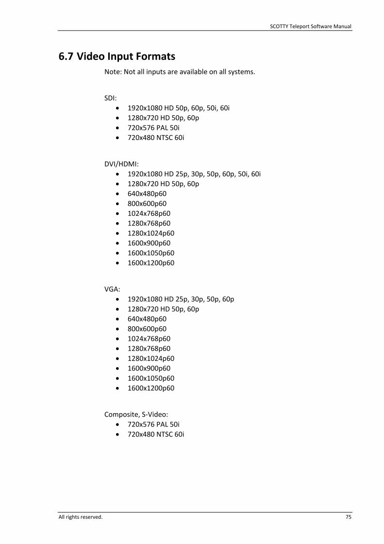
SCOTTY Teleport Software Manual
All rights reserved. 75
6.7 Video Input Formats Note: Not all inputs are available on all systems.
SDI:
1920x1080 HD 50p, 60p, 50i, 60i
1280x720 HD 50p, 60p
720x576 PAL 50i
720x480 NTSC 60i
DVI/HDMI:
1920x1080 HD 25p, 30p, 50p, 60p, 50i, 60i
1280x720 HD 50p, 60p
640x480p60
800x600p60
1024x768p60
1280x768p60
1280x1024p60
1600x900p60
1600x1050p60
1600x1200p60
VGA:
1920x1080 HD 25p, 30p, 50p, 60p
1280x720 HD 50p, 60p
640x480p60
800x600p60
1024x768p60
1280x768p60
1280x1024p60
1600x900p60
1600x1050p60
1600x1200p60
Composite, S-Video:
720x576 PAL 50i
720x480 NTSC 60i

SCOTTY Teleport Software Manual
76 All rights reserved.
6.8 Video Output Formats Note: Not all outputs are available on all systems.
DVI/HDMI, VGA:
1920x1080 HD 30p, 50p, 60p, 50i, 60i
1280x720 HD 50p, 60p
720x576 PAL 50i
720x480 NTSC 60i
640x480p60
800x600p60
1024x768p60
1280x768p60
1280x1024p60
1600x1200p60
1680x1050p60
Composite, S-Video:
720x576 PAL 50i
720x480 NTSC 60i


