85
Scratch Operating Software
Scratch Operating Software

Surface Machine Systems
2
Table of Contents
Scratch Operating Software ................................................................................. 11. About This Document .................................................................................. 41.1. Safety ................................................................................................. 41.2. Conventions .......................................................................................... 42. Introduction ............................................................................................ 62.1. Software Features.................................................................................... 62.2. Scratch 4 Machine Overview......................................................................... 72.2.1. Specifications................................................................................. 82.2.2. Comments on Specifications................................................................. 9
Scratch Velocity .............................................................................. 9Normal Load.................................................................................. 9Scratch Length ............................................................................... 9
2.2.3. Sample Thickness ........................................................................... 102.3. Location ............................................................................................. 102.4. Basic Assembly ...................................................................................... 113. Parts Description ......................................................................................123.1. The Scratch 4 Machine .............................................................................. 123.2. The Testing Apparatus .............................................................................. 123.2.1. The Scratch Head Assembly................................................................. 13
Lower Part................................................................................... 14Upper Part................................................................................... 15
3.2.2. The Work Surface ........................................................................... 153.3. The Windows PC .................................................................................... 154. Operating the Scratch Machine.......................................................................174.1. Startup............................................................................................... 174.1.1. Visual Inspection of the Machine ........................................................... 174.1.2. Test Apparatus Power....................................................................... 17
Turning On .................................................................................. 17Turning Off .................................................................................. 18Emergency Stop ............................................................................. 18Recovering From an Emergency Stop ...................................................... 18
5. A Basic Scratch Test ...................................................................................195.1. Scratching Process .................................................................................. 195.2. Data Collected....................................................................................... 195.3. Further Analysis ..................................................................................... 196. Installing the Scratch Operating Software ...........................................................206.1. Installation Requirements........................................................................... 206.1.1. Verifying Driver Version..................................................................... 206.2. Installation Directions............................................................................... 227. Using the Scratch Operator Software ................................................................287.1. Starting the Software ............................................................................... 28

Surface Machine Systems
3
7.2. The Main Interface .................................................................................. 287.2.1. Primary Features ............................................................................ 29
Test Parameters............................................................................. 29Operations .................................................................................. 30
7.3. Scratch Machine Initialization ...................................................................... 317.4. Calibration........................................................................................... 317.4.1. Importing 1.x Calibration Files .............................................................. 317.4.2. Saving Calibration Scales.................................................................... 387.4.3. Creating New Calibration Scales ............................................................ 39
Calibrating the Normal Load Sensor ........................................................ 40Calibrating the Tangential Load Sensor..................................................... 49Creating an X Position Calibration Scale .................................................... 59Creating a Depth Calibration Scale ......................................................... 64
7.4.4. Resetting a Calibration Scale................................................................ 727.4.5. Clearing a Calibration Scale ................................................................. 727.5. Jogging the Scratch Head ........................................................................... 727.6. Clearing a Halt Operations .......................................................................... 737.7. Running a Scratch Test .............................................................................. 747.8. Saving a Copy of the Scratch Test Data ............................................................. 797.9. Viewing Scratch Data................................................................................ 807.10. Determining MHC ................................................................................... 807.11. Saving and Loading Scratch Test Parameters....................................................... 807.12. Accessing Diagnostics ............................................................................... 817.12.1. Components................................................................................. 82
Digital........................................................................................ 82Analog ....................................................................................... 83System Information ......................................................................... 83Operations .................................................................................. 83Chart Data ................................................................................... 83
8. Troubleshooting .......................................................................................848.1. Scratch Machine Not Found at Startup ............................................................. 84

Surface Machine Systems
4
1. About This Document
This document covers the operation and use of the SMS Scratch 4 Machine and the Scratch Operating
Software. This document does not cover analytical techniques or basic scratch or tribology science. For
other documentation on these or related subjects, see our website at:
http://www.surfacemachines.com
For additional information, or the latest software and manuals for your Scratch 4 Machine, you may contact
Surface Machine Systems at:
http://www.surfacemachines.com
This website will have our latest software, manuals, and contact information for support.
1.1. Safety
As with all lab equipment, safety should be the foremost concern of anyone using heavy or powerful
equipment. Along with all other safety procedures that should be taken in a lab setting, please remember:
► Wear eye protection at all times.
► Secure long hair or loose clothing so that it does not become entangled in the equipment.
► Do not place your hand or any other object in the open “slot” on the Scratch 4 Machine.
► If there are any issues with the software or mechanical systems, immediately shut the Scratch 4 Machine
down by hitting the Big Red Button. If there is an issue, contact Surface Machine Systems before starting
the machine or running any more tests.
► Do not leave loose objects on the machine.
1.2. Conventions
When referring to interface elements of the software, we try to include images of the software interface as it
would appear. The elements you will be interacting with at any time will be marked with a red box.
Critical notes will appear in Red Boxes.

Surface Machine Systems
5
Notational items or warnings will appear in Yellow Boxes.

Surface Machine Systems
6
2. Introduction
The Scratch 4 Operating Software 2.1.0 is the newest implementation of the operating software for your
Scratch 4 Machine. This version is a ground-up rewrite, designed to address the major outstanding issues of
the 1.x series Scratch Operating Software, as well as to reduce the complexity of using and maintaining the
Scratch 4 Machine.
2.1. Software Features
Rising Load and Constant Load Tests – you can still perform rising, falling, and constant load tests.
Jogging and Positioning – the software allows you to jog or position the head above your samples.
Jogging is used to perform setup prior to conducting a test. Jogging the head should never be used to
perform a scratch test.
Projects – the concept of a Project has been introduced, which allows you to save your Scratch settings for
use and re-use at a later date.
Automatic Save File Increments – you can specify a directory and a sample name, and the software will
automatically save scratch data using your sample name in consecutively-numbered files.
Integrated Scratch Data Viewer – the operating software now includes an integrated Scratch Data
Viewer, which allows you to view your data without resorting to third party tools. Additionally, the Scratch
Data Viewer can automatically find the onset of Scratch, and display only the Scratch region of the Scratch
Data. The Scratch Data Viewer can also be used to load old Scratch Data files.
Integrated Diagnostics – the software now includes real-time diagnostic information for use by SMS
support staff.
NOTE: the options on this screen can be potentially hazardous to your Scratch Machine. Do not usethe options unless directed to do so by a qualified technician.
Integrated Calibration – calibration has never been simpler or more powerful! The new calibration system
allows for full-range table-based interpolation over the sensor range. Calibration has become much easier
with the new Calibrator screen. You can now take readings directly within the operating software, and these

Surface Machine Systems
7
readings are translated into calibration profiles automatically. A special screen is available for Depth
calibration.
Scratch Machine Finder – now, when the machine is power cycled, you do not have to restart the
Operating Software. New operating logic allows the Operating Software to recover when the machine is
halted, and to discover the machine when attached. Additionally, the software includes options to clear
emergency halts, and to perform first-boot operations to reset the Scratch 4 Machine without restarting the
Scratch Operating Software.
Smaller, Easier Installation – the new Scratch 4 Operating Software is less than 1 MB in size, and includes
a basic Windows Installer. This compares to the previous installations which were greater than 1 GB in size
each (almost 2000 times as big!)
Extra Tools – the Scratch 4 Operating Software includes two new tools with the installation: a stand-alone
Scratch Data Viewer, and a stand-alone Machine Discovery Tool. The first tool can be used to inspect and
graph Scratch Data without resorting to third-party tools or having to keep the Scratch Operating Software
running. The second tool allows you to determine if you Scratch Machine is appropriate connected and
powered on without having to start the Scratch Operating Software.
2.2. Scratch 4 Machine Overview
The Scratch 4 Machine is an efficient, easy-to-use, device that generates controlled scratches and mars on a
variety of surfaces including polymers, metals, wood, glass, and ceramics. The Scratch 4 Machine applies
controlled constant or rising loads to the scratch tip, while translating the scratch tip across the surface of a
sample for a specified length at a desired velocity. The Scratch 4 Machine is capable of performing ASTM
D7027-05 and ISO 19252 scratch standard tests as well as replicating other popular tests. This manual will
help you set up, operate, and maintain your Scratch 4 Machine.
Surface Machine Systems
8
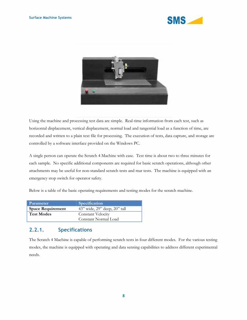
Using the machine and processing test data are simple. Real-time information from each test, such as
horizontal displacement, vertical displacement, normal load and tangential load as a function of time, are
recorded and written to a plain text file for processing. The execution of tests, data capture, and storage are
controlled by a software interface provided on the Windows PC.
A single person can operate the Scratch 4 Machine with ease. Test time is about two to three minutes for
each sample. No specific additional components are required for basic scratch operations, although other
attachments may be useful for non-standard scratch tests and mar tests. The machine is equipped with an
emergency stop switch for operator safety.
Below is a table of the basic operating requirements and testing modes for the scratch machine.
Parameter SpecificationSpace Requirement 43” wide, 29” deep, 20” tallTest Modes Constant Velocity
Constant Normal Load
2.2.1. Specifications
The Scratch 4 Machine is capable of performing scratch tests in four different modes. For the various testing
modes, the machine is equipped with operating and data sensing capabilities to address different experimental
needs.

Surface Machine Systems
9
Parameter RangeSample Thickness 0 – 12.5 mm
Z-Load Cell (Normal) 0.05 – 200 N
X-Load Cell (Tangential) ± 200 N
Z-Displacement Sensor (Depth) 0 - 5 mm
X-Displacement Sensor(Position)
Full scale
Scratch Velocity 0 – 400 mm/s
2.2.2. Comments on Specifications
Scratch Velocity
Impulsive Effect – Due to the abrupt change of movement of the Scratch Head Assembly at the beginning
and end of tests, there will be a record of sudden increase in the tangential force. This tangential force is
called the impulsive effect. Such an impulsive effect will become more apparent with higher scratch
velocities. When selecting a scratch velocity and interpreting data, users are to take note of such an effect.
Normal Load
Initial Load Constraints – The minimum load is 0.5 N.
Scratch Length
Tip Starting Point
Scratch Tip
Sample
Backing Plate (Optional)
Work Surface

Surface Machine Systems
10
2.2.3. Sample ThicknessThe maximum allowable distance between the mounting surface and the scratch tip is 25 mm. Therefore
maximum thickness of a sample must be no more 25 mm measured from the sample’s bottom surface to the
highest point on the sample’s top surface. Users should also take note of any existing curvature when
determining the sample’s maximum thickness.
The minimum sample thickness is to be determined by the user, taking into account the relative hardness of
the sample and the load of the scratch. If the sample is very thin and soft relative to the normal load, there
may be a possibility that the tip will plough through the sample and damage the machine’s work surface. As a
result, the scratch tip, work surface, and other components of the machine may be damaged. It is very
important that the work surface remains undamaged in order to execute scratch tests correctly.
When conducting tests on very thin or very soft specimens, it is recommended to use a backing plate from a
hard, smooth, material such as polycarbonate or aluminum. Backing plates can also be acquired from Surface
Machine Systems. The backing plate should be thick enough to prevent gouging and should be clamped
between the specimen and the work surface.
Finding a solid, secure, vibration-free location for the Scratch 4 Machine is critical for acquiring the best
scratch test results.
2.3. LocationThe machine should be placed on a sturdy workbench or laboratory table. The workspace should be clean,
dry and free from anything that could potentially damage the machine or its components (volatile chemicals,
bottles that could fall over, high pressure devices, loose paper, etc.). Ample space should be allowed for the
operator to access the Testing Apparatus and User Interface System conveniently.
The user should avoid locating the unit next to large machinery which may generate interference or
mechanical vibration. This includes equipment such as power generators, air conditioning units, hydraulic
pumps, air compressors, induction furnaces, etc. The electric fields, magnetic fields, and mechanical vibration
produced by such equipment can cause interference in the sensors, which will compromise the experimental
data.
If the machine must be moved on a regular basis, it is recommended that a sturdy cart for this purpose be
acquired before the machine is installed. The machine is very heavy and cumbersome, and not easy to

Surface Machine Systems
11
relocate once it is installed. Surface Machine Systems has carts specifically designed for use with your Scratch
4 Machine.
The machine should be leveled once it is positioned for use. This is done by placing a spirit level on the work
surface and then adjusting the feet on the machine until the spirit level reads level. Either a “bulls-eye” or
cylinder-type level may be used. If a standard level is used then check both the X and Y directions (width and
depth).
2.4. Basic AssemblyFor the assembly of the machine, the basic tasks are as follows.
1. Unpack the various components of the machine.
2. Place each component in its desired location.
3. Connect all cables to the required ports. Each cable is explicitly labeled to avoid confusion.
The scratch head assembly of the Scratch 4 Machine is fabricated to high precision. Extreme care mustbe exercised when handling the machine. Never use the scratch head as a handle.
4. Remove all zip ties or other restraining devices on the Scratch 4 machine.
5. Install the scratch software:
a. If your Windows PC does not have NI-DAQmx software installed, perform a default installation of
this software. If you Scratch 4 machine shipped with a Windows PC, SMS has already performed
this installation for you.
b. Download or copy the Scratch 4 software installer to the Windows PC.
c. If the software is compressed (it will show with a Zip icon, or have the .zip extension), decompress
the software. Make note of where the software is decompressed to.
d. In the software distribution folder, double-click the Setup icon, and perform a default installation of
the Scratch 4 software.
6. Install a scratch tip.
7. Plug the main power cable into a wall outlet.
Surface Machine Systems
12
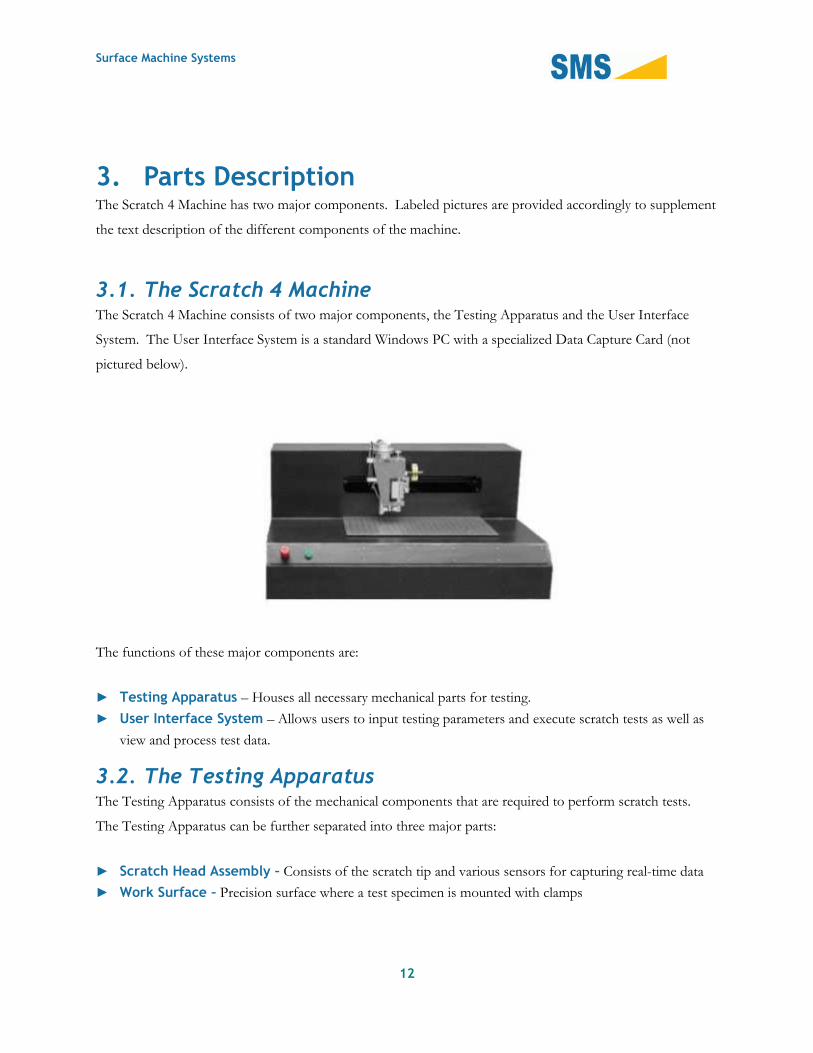
3. Parts DescriptionThe Scratch 4 Machine has two major components. Labeled pictures are provided accordingly to supplement
the text description of the different components of the machine.
3.1. The Scratch 4 MachineThe Scratch 4 Machine consists of two major components, the Testing Apparatus and the User Interface
System. The User Interface System is a standard Windows PC with a specialized Data Capture Card (not
pictured below).
The functions of these major components are:
► Testing Apparatus – Houses all necessary mechanical parts for testing.
► User Interface System – Allows users to input testing parameters and execute scratch tests as well as
view and process test data.
3.2. The Testing ApparatusThe Testing Apparatus consists of the mechanical components that are required to perform scratch tests.
The Testing Apparatus can be further separated into three major parts:
► Scratch Head Assembly – Consists of the scratch tip and various sensors for capturing real-time data
► Work Surface – Precision surface where a test specimen is mounted with clamps

Surface Machine Systems
13
3.2.1. The Scratch Head AssemblyThe scratch head assembly is the only removable part of the Testing Apparatus. It houses the scratch tip and
various sensors used for data capturing. Great care must be taken when handling the assembly as its parts are
fabricated to high precision. Individual parts with their functions are listed as follows:
Scratch Head Assembly
Work Surface

Surface Machine Systems
14
Lower Part
► Scratch Tip Column – Holds the scratch tip
► Scratch Tip (Stylus) – Ploughs the surface of the specimen
► Scratch Tip Retaining Screw – Holds the scratch tip in place within the scratch tip column
► X-Load Sensor – Senses the tangential load
► Head Clamp and Head Clamp Bolt – Used to set the scratch tip column to the desired height
Scratch Tip Column
Scratch Tip (Stylus)
Scratch Tip Retaining Screw
X-Load Sensor
Head Clamp
Head Clamp Nut
Air Supply Connection
Load Generator
Pneumatic Diaphragm
Z-Depth Sensor
Height Adjustment Knob
Counterweight
Load Head Setscrew

Surface Machine Systems
15
Upper Part
► Air Supply Connection – Connects the load head to the pneumatic Z-load control
► Load Generator – Contains the pneumatic diaphragm
► Pneumatic Diaphragm – Receives air from the pneumatic Z-load control and expands to apply
load to the scratch tip column
► Z-Linear Encoder – Senses vertical displacement (depth)
► Height Adjustment Knob – Used to set tip height
► Load Head Setscrew – Used to calibrate the Load Head
3.2.2. The Work SurfaceThis is a stainless steel surface on which the test specimen is mounted. The clamps that hold the specimens
are attached by means of the threaded holes on the work surface. The work surface should be kept free of
debris or dirt, and care must be taken to prevent damage to the work surface. The work surface is machined
to a very high degree of flatness. Any dents, mars, or scratches in the work surface will degrade the accuracy
of readings. You should never leave tools or hard objects on or near the work surface.
3.3. The Windows PCThis component is used by the user to input the testing parameters for scratch tests; it includes a computer, a
flat-panel monitor, keyboard, and optical scroll mouse.

Surface Machine Systems
16

Surface Machine Systems
17
4. Operating the Scratch Machine
With a little practice, the basic operation of the Scratch 4 Machine can be mastered by anyone.
4.1. Startup
4.1.1. Visual Inspection of the Machine
Before testing a specimen, the Testing Apparatus should be carefully inspected.
1. Check for loose bolts in the scratch head, mounting brackets, bearings, etc.
2. Make sure that adequate clamps are available
3. Inspect the scratch tip for damage and make replacement if needed
4. Check for interference between moving parts
5. Make sure that the computer is turned on and functioning
6. Make sure that the connections to the computer are secure
4.1.2. Test Apparatus PowerThe main power switch for Scratch 4 Machine is located on the left side of the Testing Apparatus. This
switch will supply power to the Testing Apparatus. A red emergency stop switch is located next to power
switch. This switch must be in the out position for the machine to turn on. A green light indicates that
power is being supplied.
Turning On
In order to turn the machine on, follow these steps:
1. Make sure you have exited or quit the Scratch 4 software.
2. Twist the red button in the direction of the arrows so that it “pops” out.
3. Depress the green button to turn the machine on. The green button will illuminate to indicate that the
machine is turned on.
4. Open the Software by finding the Scratch 4 software in the Windows Start Menu.
The machine must be turned on (green light illuminated) BEFORE the scratch software is started. Themachine will not operate correctly if the software is started first.

Surface Machine Systems
18
The machine should be turned on and allowed to warm up for at least 15 minutes before performing atest. This allows the electronics to warm up to ensure accurate data collection.
Turning Off
► Push the red button.
Emergency Stop
► Push the red button.
The power off button is designed to be used as an emergency stop button. Although we do notrecommend using excessive force, it is designed to be used in panic situations.
Recovering From an Emergency Stop
The machine may turn itself off, or be turned off automatically for a variety of reasons. In most cases, the
machine is turned off to prevent head crash. A head crash is any scenario in which the head may strike any
person, or any hard or heavy object. The machine may automatically detect other scenarios in which it
emergency stops, such as overload, limit-switch cutoff, or power failure.
Although the head moves smoothly, it is very heavy and has considerable momentum. The machine iscapable of generating enough energy to partially or fully destroy the Scratch Head, or to permanentlydamage the controls and sensors in the Scratch head.
The Scratch machine software is designed to automatically recover the machine from an emergency stop.
1. Make sure you have exited or quit the software.
2. Twist the red button in the direction of the arrows so that it “pops” out.
3. Depress the green button to turn the machine on. The green button will illuminate to indicate that the
machine is turned on.

Surface Machine Systems
19
5. A Basic Scratch Test
The Scratch 4 Machine is capable of running a wide variety of scratch and mar tests, including those specified
under ASTM D7027-05 or ISO 19252:2008. The Scratch 4 can also emulate other scratch standards
developed by others. Some tests may require the use of specialized scratch styli. These may be acquired from
Surface Machine Systems. The basic operation of a scratch using the Scratch 4 Machine and the Operating
Software will result in an ASTM or ISO standard scratch test. Other types of tests may require specialized
software, procedures, or equipment.
5.1. Scratching Process
First, the machine operator inputs the desired test parameters into the Scratch 4 machine’s control computer.
This includes the test length, velocity, and loading type (constant or rising load). The Scratch 4 machine then
performs the test as programmed. During the test cycle the indenter (tip) is first lowered down until the
desired starting load is achieved. Then the tip translates across the specimen at the desired velocity, while
either maintaining a constant load or applying a rising load. Test data is collected and saved during the test.
Afterwards, the test data and the scratched specimen are ready for analysis.
5.2. Data Collected
The Scratch 4 Machine collects four channels of data for each experiment. These include Normal (Z)
direction load, Tangential (X) direction load, Scratch Depth (Z depth), and the tangential position of the
scratch tip (X position). These four data channels are collected according to a time base interval (data capture
rate), which may be set by the operator.
5.3. Further Analysis
The Scratch 4 Machine performs Scratch tests and records data measured during each test. It is up to the
user to determine the application and content of the resulting data. For visual (aesthetic) competitive analysis,
Surface Machine Systems also provides software tools for helping with analytical processes.

Surface Machine Systems
20
6. Installing the Scratch Operating Software
6.1. Installation Requirements
The following software packages are required to use the Scratch 4 Machine:
► The scratch operating software installer, available on the included CD or DVD, or by download at:
► http://www.surfacemachines.com/swdist/sos/
► The National Instruments Data Capture Driver: NI-DAQmx v. 9.0.2 or later (for Windows 2000/7/7
x64/Vista/Vista x64/XP), available from:
► http://joule.ni.com/nidu/cds/view/p/id/1444/lang/en
► Microsoft Windows XP SP3 or Windows Vista
► Microsoft .NET 3.5 SP1
► http://www.microsoft.com/downloads/details.aspx?FamilyID=ab99342f-5d1a-413d-8319-
81da479ab0d7&DisplayLang=en
The following hardware is required to use the Scratch 4 Machine:
► A Scratch 4 Machine
► One stylus
► One Microsoft Windows-based PC, with at least 2 GB of RAM, and an NI PCI-6220 or NI PCI-6320
data capture card.
► Serial Cable and NI Data Cable, connecting the PC to the Scratch 4 Machine
6.1.1. Verifying Driver Version
The National Instruments NI-DAQmx Driver must be version 9.0.0 or later. If your National Instruments
driver is a version prior to 9.0.0, you must upgrade the driver for the software to work. To check the version
number of your driver, follow these steps.
Surface Machine Systems
21
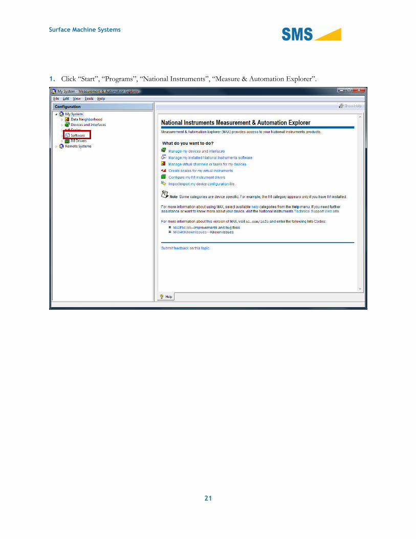
1. Click “Start”, “Programs”, “National Instruments”, “Measure & Automation Explorer”.
Surface Machine Systems
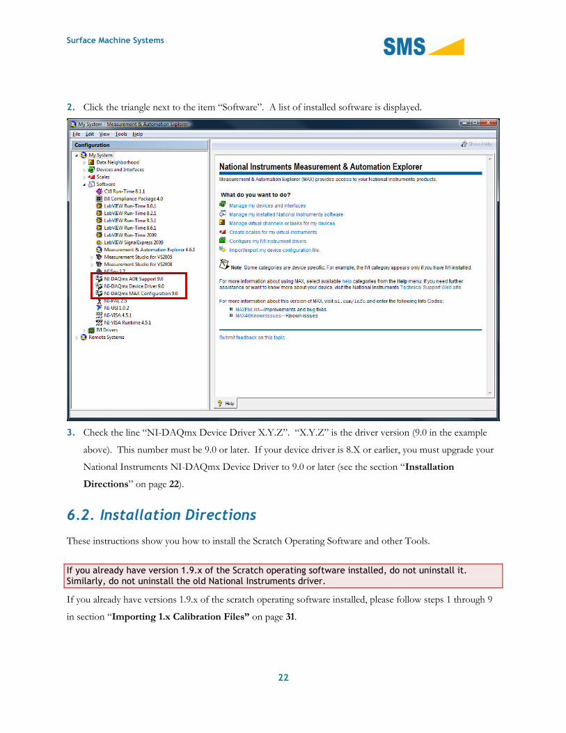
22
2. Click the triangle next to the item “Software”. A list of installed software is displayed.
3. Check the line “NI-DAQmx Device Driver X.Y.Z”. “X.Y.Z” is the driver version (9.0 in the example
above). This number must be 9.0 or later. If your device driver is 8.X or earlier, you must upgrade your
National Instruments NI-DAQmx Device Driver to 9.0 or later (see the section “Installation
Directions” on page 22).
6.2. Installation Directions
These instructions show you how to install the Scratch Operating Software and other Tools.
If you already have version 1.9.x of the Scratch operating software installed, do not uninstall it.Similarly, do not uninstall the old National Instruments driver.
If you already have versions 1.9.x of the scratch operating software installed, please follow steps 1 through 9
in section “Importing 1.x Calibration Files” on page 31.
Surface Machine Systems
23
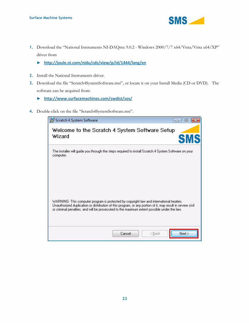
1. Download the “National Instruments NI-DAQmx 9.0.2 - Windows 2000/7/7 x64/Vista/Vista x64/XP”
driver from
► http://joule.ni.com/nidu/cds/view/p/id/1444/lang/en
2. Install the National Instruments driver.
3. Download the file “Scratch4SystemSoftware.msi”, or locate it on your Install Media (CD or DVD). The
software can be acquired from:
► http://www.surfacemachines.com/swdist/sos/
4. Double-click on the file “Scratch4SystemSoftware.msi”.

Surface Machine Systems
24
5. Follow the installation instructions.
Surface Machine Systems
25
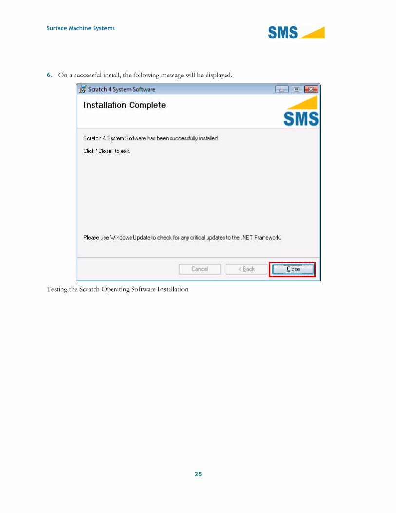
6. On a successful install, the following message will be displayed.
Testing the Scratch Operating Software Installation

Surface Machine Systems
26
1. Click the Windows Start Button
2. Click “All Programs”
3. Click “Surface Machine Systems”
4. Click “Scratch Viewer”. A window as follows opens.
5. If you receive an error, uninstall the software, and follow the steps outlined above.
6. Turn on the Scratch Machine as described in section 4.1.2.
7. Follow steps 1 through 3 of this section
8. Click “Machine Finder”. A window as follows opens.

Surface Machine Systems
27
9. Select the first COM Port in the drop-down list.
10. Select the “Select Port” button.
11. The “Details” section should show the phrase “Machine is responding on this port”. Make a note of
which COM Port you selected.
12. If the phrase “Machine is not responding on this port.” is shown, try selecting other Ports from the list.
If no Ports find a machine, check the following:
e. The machine serial cable and data cable are firmly connected to this computer.
f. The machine power cable is firmly connected, and the machine is powered on (green light)
g. If the machine does not power on, or does not respond, refer to your Scratch 4 Machine User Guide
for troubleshooting information.

Surface Machine Systems
28
7. Using the Scratch Operator Software
7.1. Starting the Software
The Scratch 4 Machine should always be turned on prior to starting the Scratch Operating Software.
1. Ensure that the Scratch 4 Machine is plugged in to the PC via the Data Capture Cable and the Serial
Cable.
2. Turn on the Scratch 4 Machine. If the Scratch 4 Machine has been off, let it warm up for 10 minutes
prior to performing tests.
3. Select the Scratch Operating Software button from the Start Menu, or double-click the icon on your
desktop.
7.2. The Main Interface
When you open the Scratch Operator, you will be presented with the following window.

Surface Machine Systems
29
This is the “Main Control Window”, and all major functionality of the Scratch Machine can be accessed from
this window. When the software is opened, you will see some activity in this window below the “Halt
Operation” button. The interface will also be inaccessible for several seconds after it is started while the
machine is automatically reset. When the green “MACHINE READY” label is visible, the machine is ready
for use.
7.2.1. Primary Features
Test Parameters
This area is used to set Scratch Test Parameters during a Scratch Test. Pressing the “Run Test” button will
cause the Scratch 4 Machine to run a scratch test using the currently visible parameters.

Surface Machine Systems
30
Warning: Running a test prior to calibration, or without a sample and styli in the machine may causepermanent damage to your Scratch 4 Machine.
Please see the section “Calibration” on page 31 to calibrate the Scratch 4 Machine prior to running your first
test. Please see the section “Running a Scratch Test” on page 74 to see how to run a test.
► Save Directory. This is the directory (folder) where test results will be automatically saved after each
test. You can choose the output directory by selecting the “…” button next to the text box, and selecting
an output directory.
► Show Files. This button opens the directory where the scratch data files are automatically saved.
► Sample Name. This is the name of the sample, and is also the “base name,” used to determine the file
name of the test results when automatically saved. The test results will be saved in a file in the format
<base name>_<number>.csv, where <base name> is the name entered in the “Sample Name” box, and
<number> is a number which is incremented for each test and starts with 1. For instance, if your sample
name is PP1000, then the first test results will be saved as “PP1000_1.csv” in the “Save Directory”
folder. The second set of test results will be called “PP1000_2.csv”. The software will not overwrite old
test results.
► Comments. These are test-specific comments which you can specify.
► Run Test. This button runs a Scratch test.
► View Data. This button will open the Scratch Data Viewer with the results of the last scratch test
displayed. The Scratch Data Viewer can also be used to look at other scratch test data files.
Operations
This section includes basic machine operations that are not part of a test. These operations are:
► Jog Head. Jogging the head means to move it left or right. The jog head operation works in
millimeters. Pressing the “Left” button will move the head to the left. Pressing the “Right” button will
move the head to the right. Use these operations to position the head over a sample.
The Jog Head functions should never be used to run a scratch test. This can seriously damage themachine. Only the “Run Test” button should be used for this purpose, and only when the machine isproperly calibrated and setup for testing.
► Halt Operation. The Halt Operation button can be used to halt all machine operations currently in
progress. Once the Halt Operation button is pressed, the machine will attempt to come to a complete

Surface Machine Systems
31
halt. The machine will not respond to any further operation requests until the Halt is cleared. See
“Clearing a Halt Operation” below.
The Halt Operation button should not be used to perform an Emergency Halt. The Halt Operationbutton is not guaranteed to stop the machine. The only method guaranteed to stop the Scratch 4Machine is the large red STOP button on the front of the machine. Never attempt to use the HaltOperation button to perform an Emergency Halt.
7.3. Scratch Machine Initialization
When the software first starts, if the Scratch 4 Machine is found, the software will perform an automatic
hardware initialization. If the software is started up before the Scratch 4 Machine is powered on, then a
manual reboot must be performed to initialize the Scratch Machine.
1. Click “Tools”, “Reset Scratch Machine”
You will hear clicking noises, and a soft electronic sound. The interface will be inaccessible for a few
seconds. When the operation is complete, the interface will become accessible again, and ready to perform
scratch tests or other operations.
7.4. Calibration
Calibration is now easier than ever. You can import and save your old Calibration Files from the 1.9.x series
of Scratch Operating Software, or create new Calibration tables simply and easily.
7.4.1. Importing 1.x Calibration Files
When upgrading from the 1.9.x series of software to 2.1.0 it is possible to import your existing calibration
information into the new software package, although this is not a requirement. The following instructions
can be used if you would like to use your existing 1.9.x calibration information until your next routine
scheduled calibration.

Surface Machine Systems
32
1. Close the Scratch Operating Software 2.1.0. This must be closed prior to following these directions.
2. Open “Measure & Automation Explorer”

Surface Machine Systems
33
3. Click “File”, “Export…” The following window will open.

Surface Machine Systems
34
4. In the “To file” text box, enter the location on disk you would like to save the export file, or use the “…”
button to select.
5. Click “Next >”

Surface Machine Systems
35
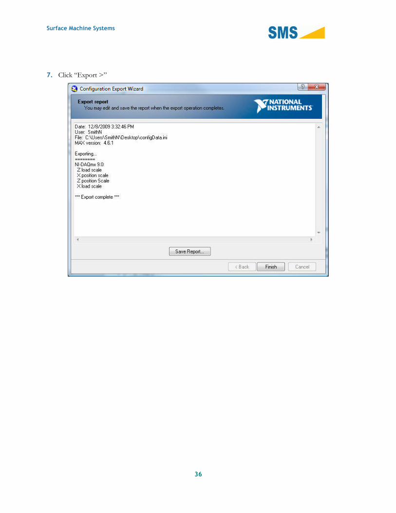
6. Open the “Scales” item, and check the four Scales shown: “Z Load scale”, “X position scale”, “Z
position Scale”, and “X load scale”.
Surface Machine Systems
36
7. Click “Export >”
Surface Machine Systems
37
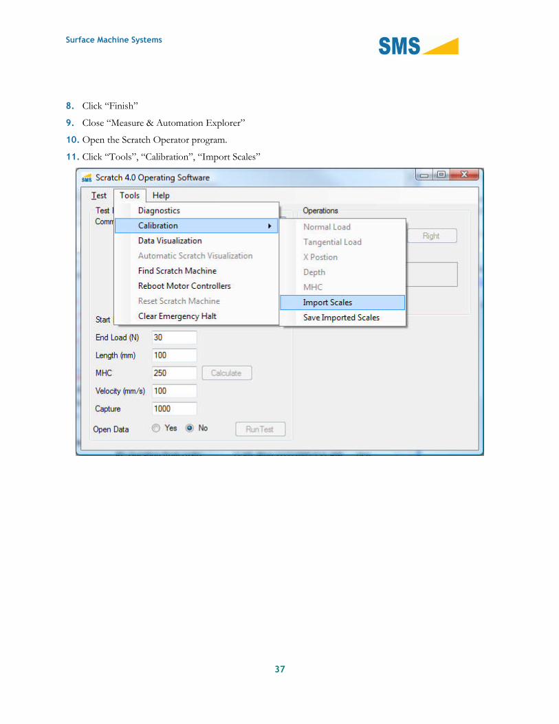
8. Click “Finish”
9. Close “Measure & Automation Explorer”
10. Open the Scratch Operator program.
11. Click “Tools”, “Calibration”, “Import Scales”

Surface Machine Systems
38
12. Choose the export file from disk.
13. Click “Open”
7.4.2. Saving Calibration Scales
To Save Calibration Scales:

Surface Machine Systems
39
1. Click “Tools”, “Calibration”, “Save Imported Scales”
Calibration Scales will be saved and automatically loaded in the future.
7.4.3. Creating New Calibration Scales
The general process for creating new calibration scales is as follows. Calibration should be performed on a
semi-regular basis. If the machine is used on a daily basis, the following table of calibration is recommended:
Sensor PeriodNormal Load Monthly or when movedDepth Monthly or when movedX-Position When moved or suspectTangential Laod Quarterly or when moved
The basic procedure for performing a Calibration is as follows.
Surface Machine Systems
40
1. Select the Scale you would like to create (Normal Load, Tangential Load, X Position, Depth).
2. Apply a known load or position to the sensor.
3. Take a measurement using the built-in measurement reading tool.
4. Record the known load or position.
5. Use the automatic calibration processing tool.
6. Validate the calibration.
If, at any time, you make a mistake while creating a scale, you may reset the scale. You can do so byclicking “Calibration”, “Reset Calibration.”
Calibrating the Normal Load Sensor
Tools
► Normal Load Calibration Sleeve
► Normal Load Calibration Piston
► 1kg calibrated mass
► Dummy Plaque
► Scratch Stylus
► Assistant

Surface Machine Systems
41
Steps
1. Ensure the Scratch machine has been turned on for at least 15 minutes prior to the beginning of the
calibration procedure.
2. With the machine turned on, start the Scratch Operating Software. Let the software complete normal
startup routines.
3. From the Main Window, click “Tools”, “Calibration”, “Normal Load”. The following window will open.
This is the Calibrator Window.
4. To calibrate the Normal Load, the previous calibration must first be cleared. Click “Calibration”, “Clear
All”.

Surface Machine Systems
42
5. The first step in calibration is to find the Zero Point, or the no load data point.
a. Place the dummy plaque underneath the Scratch Head. Make sure a scratch tip is secured in the
Scratch Head.
Surface Machine Systems
43
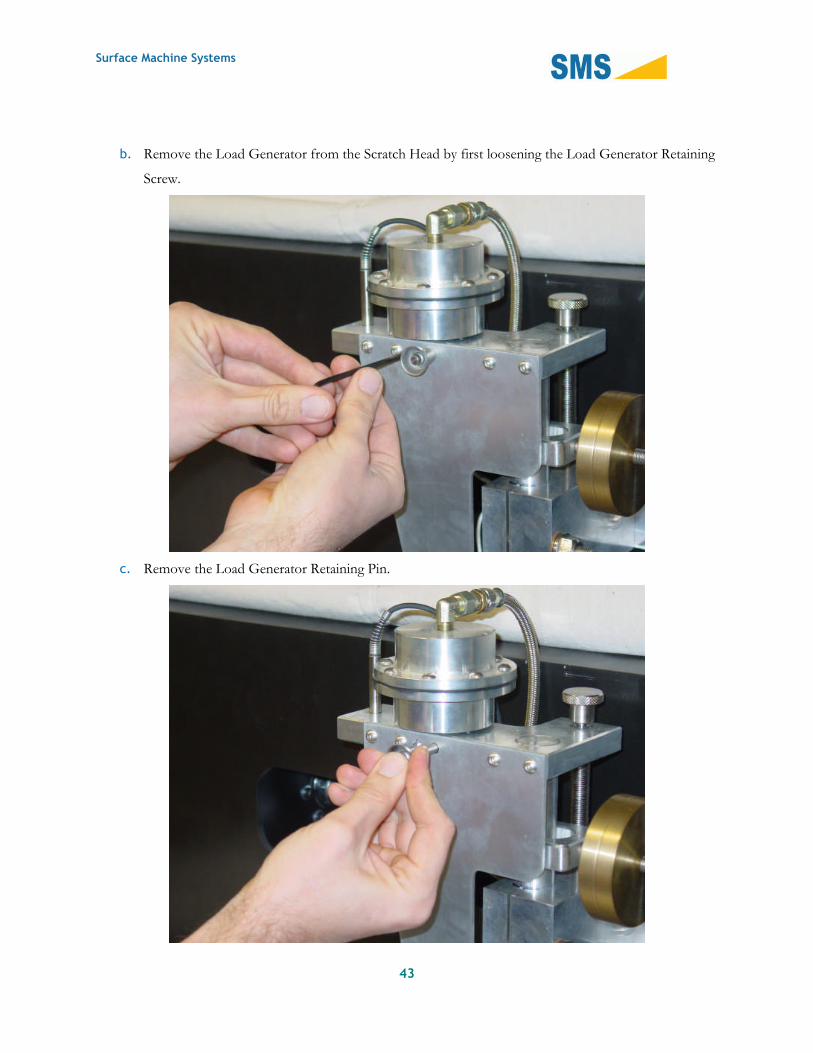
b. Remove the Load Generator from the Scratch Head by first loosening the Load Generator Retaining
Screw.
c. Remove the Load Generator Retaining Pin.

Surface Machine Systems
44
d. Remove the Load Generator Head Assembly and set it aside.

Surface Machine Systems
45
e. Have your assistant hold the column down to the plaque by pressing down on the lower Scratch
Column yoke.
f. While your assistant holds the column down as shown, click the “Sample” button in the Calibrator
Window to take a Sample Reading.
Surface Machine Systems
46
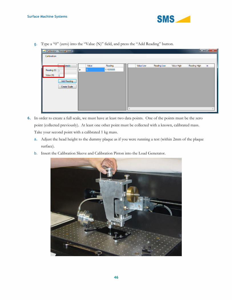
g. Type a “0” (zero) into the “Value (N)” field, and press the “Add Reading” button.
6. In order to create a full scale, we must have at least two data points. One of the points must be the zero
point (collected previously). At least one other point must be collected with a known, calibrated mass.
Take your second point with a calibrated 1 kg mass.
a. Adjust the head height to the dummy plaque as if you were running a test (within 2mm of the plaque
surface).
b. Insert the Calibration Sleeve and Calibration Piston into the Load Generator.

Surface Machine Systems
47
c. Place the 1 kg mass on top of the Calibration Piston. Take care that the mass is centered on the
piston and is not leaning or offset in any direction.
d. In the Calibrator Window, click the “Sample” Button.
e. Enter the Load in Newtons into the “Value (N)” field. Load in N is easily computed from the mass
in kilograms times acceleration due to gravity: 1 kg x 9.81 m/s2 = 9.81 N.
f. Click the “Add Reading” button.
Optional: Additional calibration points may be added. Additional calibration points are not required,but may improve the accuracy of the normal load measurement, especially for higher load tests. In
order to add additional points, simply repeat steps 6c to 6f for each additional mass that you wish touse. Only two data points (zero and 1kg) are necessary. Other calibration masses may be entered inany order, though the masses must be different. For example, 0 and 1 kg are required, though anadditional mass of 5 kg may also be used to add a 3rd data point.
7. When you have finished taking measurements, create a scale by clicking the “Create Scale” button.
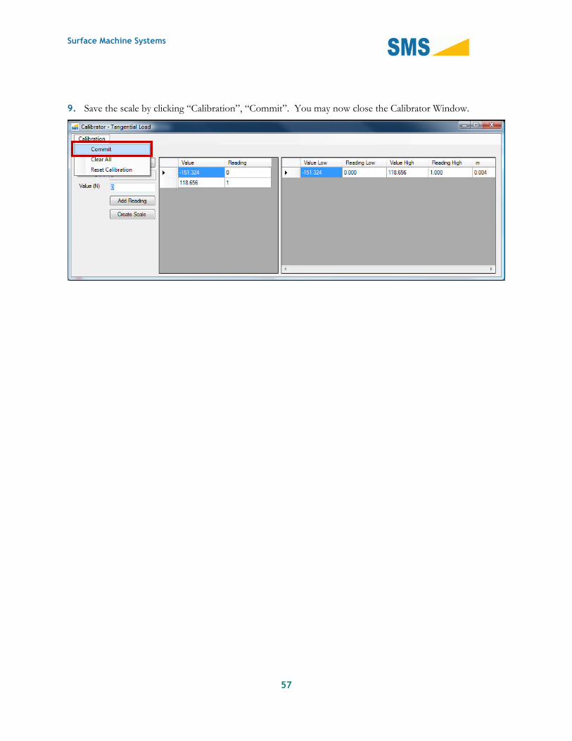
8. Save the scale by clicking “Calibration”, “Commit”. You may now close the Calibrator Window.
Surface Machine Systems
48
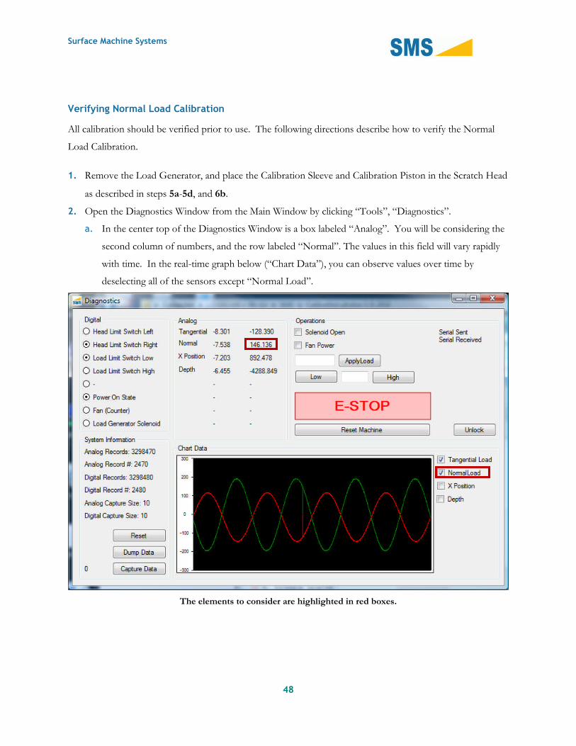
Verifying Normal Load Calibration
All calibration should be verified prior to use. The following directions describe how to verify the Normal
Load Calibration.
1. Remove the Load Generator, and place the Calibration Sleeve and Calibration Piston in the Scratch Head
as described in steps 5a-5d, and 6b.
2. Open the Diagnostics Window from the Main Window by clicking “Tools”, “Diagnostics”.
a. In the center top of the Diagnostics Window is a box labeled “Analog”. You will be considering the
second column of numbers, and the row labeled “Normal”. The values in this field will vary rapidly
with time. In the real-time graph below (“Chart Data”), you can observe values over time by
deselecting all of the sensors except “Normal Load”.
The elements to consider are highlighted in red boxes.
Surface Machine Systems
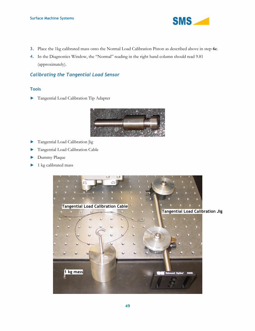
3. Place the 1kg calibrated mass onto the Normal Load Calibration Piston as described above in step 6c.
4. In the Diagnostics Window, the “Normal” reading in the right hand column should read 9.81
(approximately).
Calibrating the Tangential Load Sensor
Tools
► Tangential Load Calibration Tip Adapter
► Tangential Load Calibration Jig
► Tangential Load Calibration Cable
► Dummy Plaque
► 1 kg calibrated mass
Tangential Load Calibration CableTangential Load Calibration Jig
49
1 kg mass

Surface Machine Systems
50
Steps
1. Ensure the Scratch machine has been turned on for at least 15 minutes prior to the beginning of the
calibration procedure.
2. Jog the Scratch Head to approximately the center of the Work Surface.

Surface Machine Systems
51
3. Place the Dummy Plaque underneath the Scratch Tip.
4. Install the Tangential Load Calibration Tip Adapter in the Scratch Head. This installs just like a normal
scratch tip.
5. To create a new scale, we must get a Zero (0) point reading, and positive and negative tangential reading.
To acquire the Zero point reading, follow these steps:
a. From the Main Window, click “Tools”, “Calibration”, “Tangential Load”. The following window
opens.
Surface Machine Systems
52
b. Click “Calibration”, “Clear All”
c. In the Calibrator Window, click “Sample”, then type a 0 into the “Value (N)” text field. Click the
“Add Reading” button.
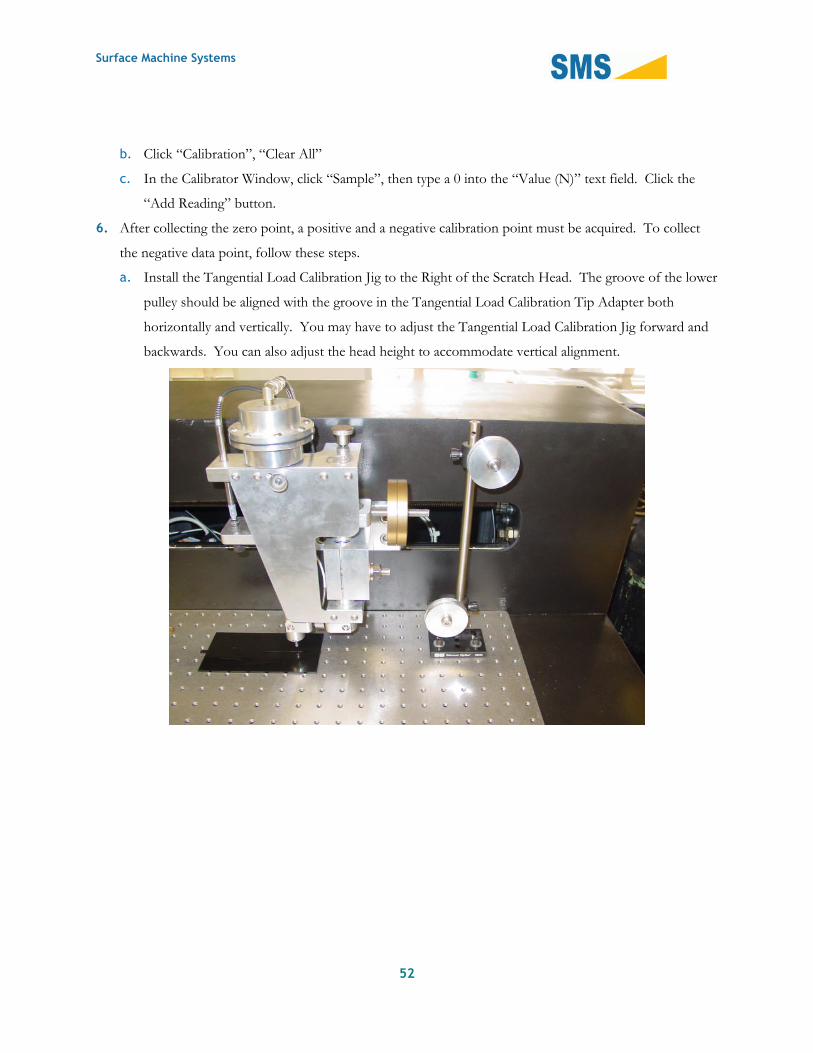
6. After collecting the zero point, a positive and a negative calibration point must be acquired. To collect
the negative data point, follow these steps.
a. Install the Tangential Load Calibration Jig to the Right of the Scratch Head. The groove of the lower
pulley should be aligned with the groove in the Tangential Load Calibration Tip Adapter both
horizontally and vertically. You may have to adjust the Tangential Load Calibration Jig forward and
backwards. You can also adjust the head height to accommodate vertical alignment.

Surface Machine Systems
53
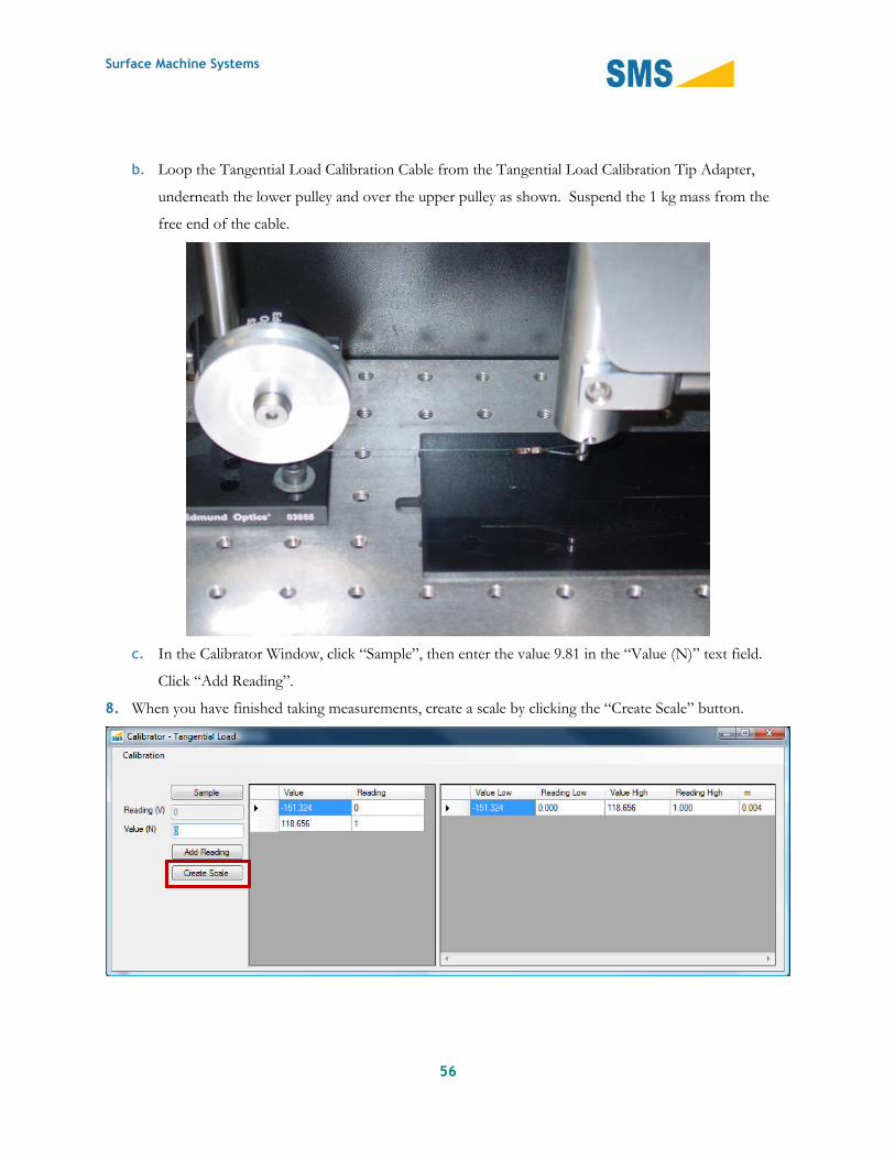
b. Loop the Tangential Load Calibration Cable from the Tangential Load Calibration Tip Adapter,
underneath the lower pulley and over the upper pulley as shown. Suspend the 1 kg mass from the
free end of the cable. Make sure the mass is hanging freely in the air and is not contacting any part
of the machine or calibration jig.

Surface Machine Systems
54

Surface Machine Systems
55
c. In the Calibrator Window, click “Sample”, then enter the value -9.81 in the “Value (N)” text field.
Click “Add Reading”.
7. Now collect a positive data point.
a. Install the Tangential Load Calibration Jig to the Left of the Scratch Head. The groove of the lower
pulley should be aligned with the groove in the Tangential Load Calibration Tip Adapter both
horizontally and vertically. You may have to adjust the Tangential Load Calibration Jig forward and
backwards. You can also adjust the head height to accommodate vertical alignment.
Surface Machine Systems
56
b. Loop the Tangential Load Calibration Cable from the Tangential Load Calibration Tip Adapter,
underneath the lower pulley and over the upper pulley as shown. Suspend the 1 kg mass from the
free end of the cable.
c. In the Calibrator Window, click “Sample”, then enter the value 9.81 in the “Value (N)” text field.
Click “Add Reading”.
8. When you have finished taking measurements, create a scale by clicking the “Create Scale” button.
Surface Machine Systems
57
9. Save the scale by clicking “Calibration”, “Commit”. You may now close the Calibrator Window.

Surface Machine Systems
58
Verifying a Tangential Load Calibration
1. Open the Diagnostics Window from the Main Window by clicking “Tools”, “Diagnostics”.
a. In the center top of the Diagnostics Window is a box labeled “Analog”. You will be considering the
second column of numbers, and the row labeled “Tangential”. The values in this field will vary
rapidly with time. . In the real-time graph below (“Chart Data”), you can observe values over time
by deselecting all of the sensors except “Tangential Load”.
Surface Machine Systems
59
2. In the Diagnostics Window, the “Tangential” reading in the right hand column should read 0.00
(approximately).
3. Attach the 1 kg mass to the Tangential Calibration Tip Adapter and Tangential Calibration Jig as
described in steps 5a - 5c above.
4. In the Diagnostics Window, the “Tangential” reading in the right hand column should read -9.81
(approximately).
5. Remove the mass.
6. Attach the 1 kg mass to the Tangential Calibration Tip Adapter and Tangential Calibration Jig as
described in steps 6a - 6c above.
7. In the Diagnostics Window, the “Tangential” reading in the right hand column should read 9.81
(approximately).
Creating an X Position Calibration Scale
Tools
► Dummy sample
Surface Machine Systems
60
Steps
1. Ensure the Scratch machine has been turned on for at least 15 minutes prior to the beginning of the
calibration procedure.
2. Center the Scratch Tip above the work surface. There should be at least 100 mm of travel in each
direction.
3. Install the dummy sample below the Scratch Tip.
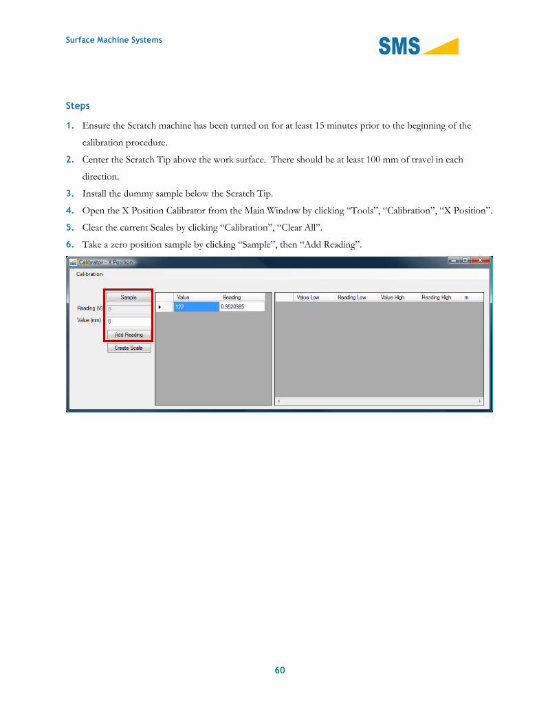
4. Open the X Position Calibrator from the Main Window by clicking “Tools”, “Calibration”, “X Position”.
5. Clear the current Scales by clicking “Calibration”, “Clear All”.
6. Take a zero position sample by clicking “Sample”, then “Add Reading”.

Surface Machine Systems
61
7. In the Main Window enter 100 into the “Jog Head” field in the “Operations” section. Press the “Right”
button.

Surface Machine Systems
62
8. In the Calibrator window press the “Sample” button. Then enter “100” into the “Value (mm)” field and
press the “Add Reading” Button.
9. Create a scale by pressing the “Create Scale” button.

Surface Machine Systems
63
10. Save the scale by clicking “Calibration”, “Commit”. You may now close the Calibrator Window.
Surface Machine Systems
64
Verifying the X Position Calibration
1. Center the Scratch Head within the Work Surface and place the dummy sample beneath it.
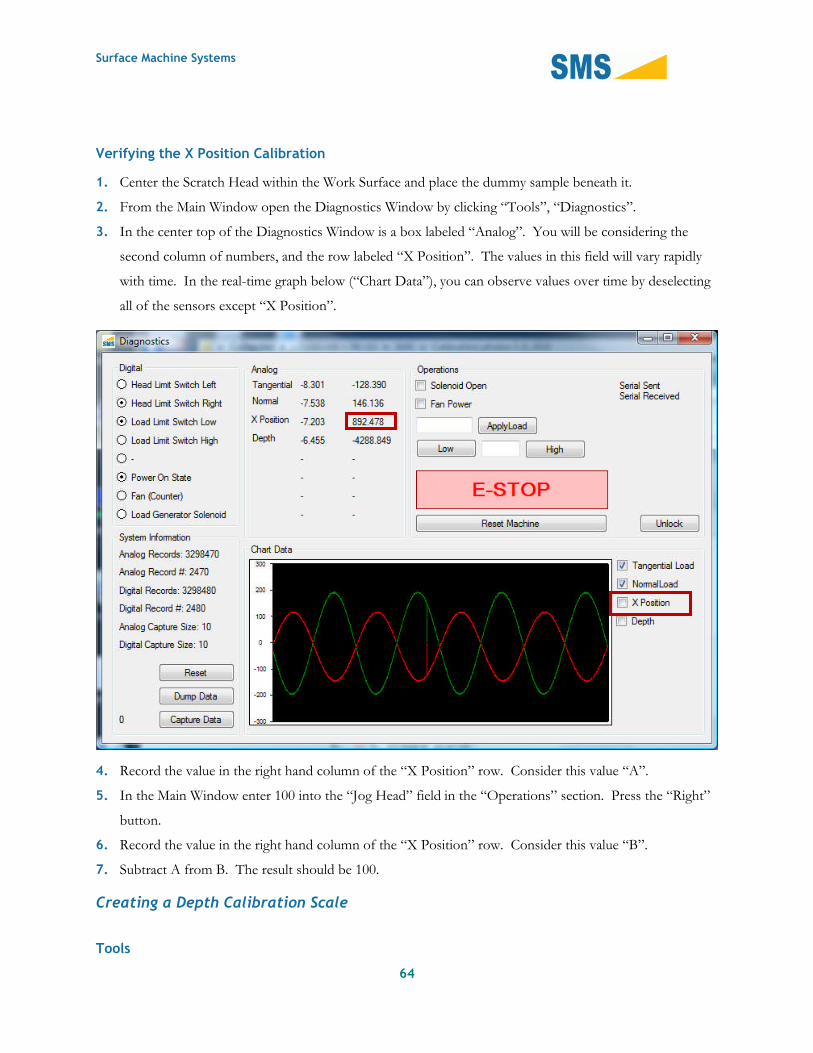
2. From the Main Window open the Diagnostics Window by clicking “Tools”, “Diagnostics”.
3. In the center top of the Diagnostics Window is a box labeled “Analog”. You will be considering the
second column of numbers, and the row labeled “X Position”. The values in this field will vary rapidly
with time. In the real-time graph below (“Chart Data”), you can observe values over time by deselecting
all of the sensors except “X Position”.
4. Record the value in the right hand column of the “X Position” row. Consider this value “A”.
5. In the Main Window enter 100 into the “Jog Head” field in the “Operations” section. Press the “Right”
button.
6. Record the value in the right hand column of the “X Position” row. Consider this value “B”.
7. Subtract A from B. The result should be 100.
Creating a Depth Calibration Scale
Tools
Surface Machine Systems
65
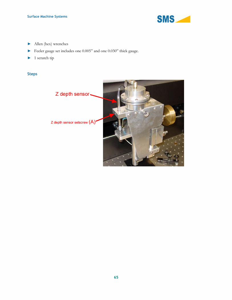
► Allen (hex) wrenches
► Feeler gauge set includes one 0.005” and one 0.030” thick gauge.
► 1 scratch tip
Steps

Surface Machine Systems
66
1. Ensure the Scratch machine has been turned on for at least 15 minutes prior to the beginning of the
calibration procedure.
2. Open the Depth Calibrator by clicking “Tools”, “Calibration”, “Depth”.
3. Click “Calibration”, “Clear All”. Click “Calibration”, “Commit”.
4. From the Main Window, open the Diagnostics Window by clicking “Tools”, “Diagnostics”.
5. In the center top of the Diagnostics Window is a box labeled “Analog”. You will be considering the first
column of numbers, and the row labeled “Depth”. The values in this field will vary rapidly with time. In
the real-time graph below (“Chart Data”), you can observe values over time by deselecting all of the
sensors except “Depth”.

Surface Machine Systems
67
6. Adjust the vertical position of the Z depth sensor until the value generated in the "Depth" field above is
as close to Zero as possible. Do this by loosening the setscrew (A) in Figure 1 and manually sliding the
sensor up or down as needed. When the sensor is correctly positioned, lock it in place by gently
tightening the setscrew. Do not over-tighten the screw as that may damage the sensor. Gentle hand
pressure is all that is needed.
Note: It will not be possible to get an "Exact" zero reading at this time. That is OK—the idea is simplyto position the depth sensor to as close to a "zero" position as possible. A value within 0.25 V and -0.25V in the first column of Depth row in Diagnostics Window is sufficient.
7. In the Depth Calibrator Window, click the “Sample” button. Then enter the value 0 in the “Value (in)”
field, and click “Add Reading”.

Surface Machine Systems
68
8. Remove any samples that may be present on the work surface, and adjust the head height so that the tip
is about 2mm above the work surface. Be sure the tip and the work surface are both clean and free of
dust or any other debris. Tighten the head clamp nut.
9. Place the 0.030” feeler gauge underneath the tip, directly on the work surface. Lower the tip to contact
the feeler gauge by lifting upwards on the brass counterweights. Lift gently so that the tip is touching the
feeler gauge, but do not use excessive force. The goal is simply to ensure the tip is firmly in contact with
the gauge, nothing more.

Surface Machine Systems
69
10. In the Depth Calibrator Window, have your assistant click the “Sample” button. Enter 0.030 into the
“Value (in)” field, and click the “Add Reading” button.
Although the Scratch Machine uses metric values internally for all data capture, control, and analysis,the Depth Calibration must be done using US Standard Gauges. Metric gauges may be used, but theirthickness must be converted to inches when entering values into the Depth Calibration Window.
11. Repeat step 9, but use a 0.005” feeler gauge. In the “Value (in)” field, enter the value 0.005, rather than
0.030.
You may use any two feeler gauge thicknesses for performing steps 9 - 11, but we recommend that thedifference in the thickness between the gauges be at least 0.025” (0.635 mm).

Surface Machine Systems
70
12. Create the scale by clicking the button “Create Scale”.
13. Save the scale by clicking “Calibration”, “Commit”. You may now close the Calibrator Window.

Surface Machine Systems
71
Verifying the Depth Calibration
1. From the Main Window, open the Diagnostics Window by clicking “Tools”, “Diagnostics”.
2. In the center top of the Diagnostics Window is a box labeled “Analog”. You will be considering the
second column of numbers, and the row labeled “Depth”. The values in this field will vary rapidly with
time. In the real-time graph below (“Chart Data”), you can observe values over time by deselecting all of
the sensors except “Depth”.

Surface Machine Systems
72
3. Place a feeler gauge of any thickness on the work surface below the scratch tip, and lower the scratch tip
to the feeler gauge as described in step 9 above. Record the value in the second column of the “Depth”
row as value “A”.
4. Place a feeler gauge of a different thickness on the work surface below the scratch tip, and lower the
scratch tip to the feeler gauge as described in step 9 above. Record the value in the second column of the
“Depth” row as value “B”.
5. Find the difference between the values “A” and “B”. The difference between the two should be the
difference in thickness in micrometers between the two gauges. For instance, if you used a 0.030” (762
µm) feeler gauge and a 0.005” (127 µm) feeler gauge, the difference should be 635 µm.
7.4.4. Resetting a Calibration Scale
If you have not committed a Calibration Scale, you may return to the previous scale as follows.
1. In the Calibrator Windows, click “Calibration”, “Reset Calibration”.
7.4.5. Clearing a Calibration Scale
1. In the Calibrator Window, click “Calibration”, “Clear All”
2. To permanently remove this calibration, follow the steps in “Saving a New Calibration Scale”
7.5. Jogging the Scratch Head
The head jogging functionality allows you to position the Scratch Head over the test piece for performing a
test, or to move the head to a more convenient location. Additionally, jogging the Scratch head can be used
as a basic diagnostic tool for determining if the Scratch Operating software is correctly communicating with
the Scratch 4 Machine.
Make sure the path of the head is clear prior to jogging the head. If the scratch head runs into clampsor other objects or debris, it can seriously damage the Scratch 4 Machine.

Surface Machine Systems
73
1. Enter the number of millimeters of translation desired in the “Jog Head” form in the “Operations”
panel.
2. Press the “Right” or “Left” buttons to move the Scratch Head.
7.6. Clearing a Halt Operations
If the “Halt Operation” button is pressed at any time, the Scratch Operating software will attempt to send
halt commands to the Scratch 4 Machine, and quit all active operations. When this occurs, the Emergency
Halt state is set. When the Scratch Operating software is in the Emergency Halt state, it will indicate the state
with bright red lettering as below. While in this state, no operations will be allowed until the state is cleared.

Surface Machine Systems
74
To clear the emergency halt state, follow these steps:
1. Click “Tools”, “Clear Emergency Halt”
7.7. Running a Scratch Test
To run a Scratch Test, follow these steps:
Surface Machine Systems
75
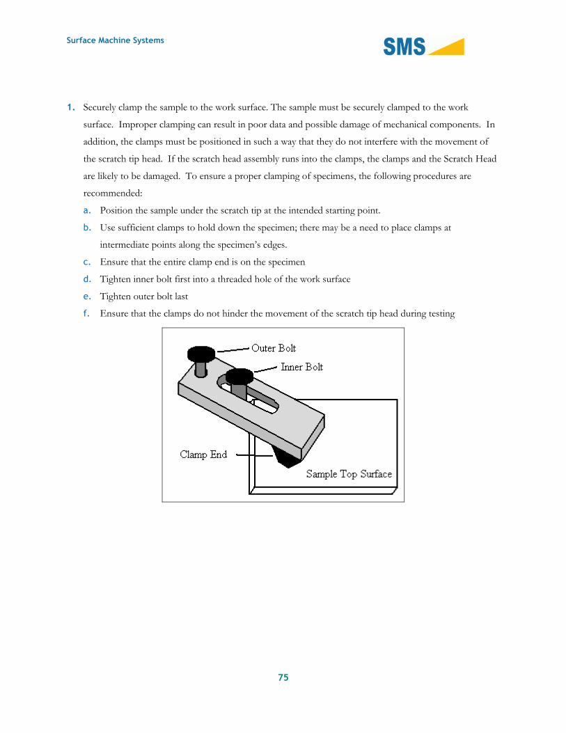
1. Securely clamp the sample to the work surface. The sample must be securely clamped to the work
surface. Improper clamping can result in poor data and possible damage of mechanical components. In
addition, the clamps must be positioned in such a way that they do not interfere with the movement of
the scratch tip head. If the scratch head assembly runs into the clamps, the clamps and the Scratch Head
are likely to be damaged. To ensure a proper clamping of specimens, the following procedures are
recommended:
a. Position the sample under the scratch tip at the intended starting point.
b. Use sufficient clamps to hold down the specimen; there may be a need to place clamps at
intermediate points along the specimen’s edges.
c. Ensure that the entire clamp end is on the specimen
d. Tighten inner bolt first into a threaded hole of the work surface
e. Tighten outer bolt last
f. Ensure that the clamps do not hinder the movement of the scratch tip head during testing

Surface Machine Systems
76
2. Clean the Scratch Tip. Prior to performing a test, the scratch tip should be inspected and cleaned of any
debris that may be attached to it. This can be done by cleaning the scratch tip with compressed air or by
gently running a cotton swab or a KimwipeTM over the scratch tip.
If it becomes necessary to clean the scratch tip with solvent, it is recommended that you use laboratory
grade solvents only. HPLC-grade or optical-grade solvents are ideal. Store-grade solvents often contain
additives or contaminants which can affect the test in undesirable ways. For example, isopropanol
(commonly known as rubbing alcohol) purchased from a pharmacy typically contains lanolin, which can
act as a lubricant during testing. SMS recommends the use of laboratory grade solvents only.
3. Adjust the head height to be within 2 mm of the top surface of the specimen. To adjust the scratch head
assembly for this requirement, follow these steps:
a. Make sure the Testing Apparatus and the Scratch 4 software are turned off. Adjusting the scratch
head while the machine is on is dangerous to the operator and may damage the machine.
b. Loosen the head clamp bolt with an 11/16-inch wrench.

Surface Machine Systems
77
c. Place the test sample under the scratch tip
d. Turn the height adjustment knob to raise or lower the head as needed. The stylus should be as close
to the sample as possible, without touching it.
The stylus can be no more than 2mm from the work surface before the test begins.
Head Clamp Nut
Height Adjustment Knob

Surface Machine Systems
78
e. Once the head height is set, tighten the head clamping nut.
f. Check if the scratch tip is within 2 mm from the top surface.
If the test session calls for testing multiple specimens of the same thickness, it is acceptable to set thescratch tip head height once for that session. However, users should periodically check if the heightclearance is sufficient to avoid damage to the scratch tip.
4. Enter the Scratch test parameters in the “Test Parameters” section.
a. Save Directory should be the location of an output folder on your computer where you want the files
saved. These files will have the name <Sample Name>_<Number>.csv. <Sample Name> is the
value entered in the following field. <Number> is an automatically incrementing number, which
starts at 1, and increments for each test.
b. Sample Name is the name of the sample, and is used to determine the scratch output file automatic
save name.
c. Comments include any additional information you would like to store with the test.
d. Start Load should be at least 0.5 N
e. End Load should be no more than 150 N
f. The length should be no more than 1200 mm
g. MHC is a material-dependent constant which is determined prior to test, as detailed in section 7.10.
h. The Velocity should be no more than 400 mm/s
i. The Capture Rate determines the number of data points per second to collect. We recommend
collecting approximately 10 points of data for every mm/s of Velocity. For instance, we recommend
1000 points per second for 100 mm/s. We recommend 10 points per second for 1 mm/s. For 200
mm/s and higher, set the Capture Rate to 2000.
5. Click the “Run Test” button.
6. If you want to view the test results immediately, click “Tools”, “Data Visualization” or the “View Data”
button in the Main Window.
NOTE: The Data Visualization window will not update after another test is run. After each test youmust go to “Tools”, “Data Visualization” in order to see the latest test data.

Surface Machine Systems
79
7.8. Saving a Copy of the Scratch Test Data
If you opened the Data Visualization window after running the test, you may save the data from this window.
1. Click “File”, “Save”.
2. Choose the name and location of the file you would like to save.
Otherwise you can save the test data from the Main Windows by clicking “Test”, “Save Scratch Data”.
The scratch information from the Test Parameters will be saved in the file.

Surface Machine Systems
80
7.9. Viewing Scratch Data
The Scratch Operator includes a copy of the Scratch Data Viewer. You can view Scratch Data Files (text files
or comma-delimited files—*.txt, *.csv) by using this tool.
1. Click “Tools”, “Data Visualization”
2. In the Scratch Data Viewer, click “File”, “Open”, and select a file.
The Scratch Data Viewer can only read files created by the Scratch Operating Software versions 1.x and 2.x.
7.10. Determining MHC
Determining MHC must be done on a per-system basis. MHC is a unit-less value which tells the Scratch 4
Machine how to generate the load required to meet test parameters. The primary component of MHC is the
hardness of the material under test. If the head-height is adjusted, or the type of material is changed, the
MHC must be recalibrated.
1. Place a spare sample of the material to be tested on the work surface, and run a test as described in
section 7.7. When running this test, put the number “200” into the MHC field. In the “End Load” field,
put the End Load that will be used for the tests being run.
2. View the results. If the ending load of the Scratch Test is higher than the expected End Load, lower the
MHC, and run another test. If the ending load of the Scratch Test is lower than the expected End Load,
raise the MHC, and run another test to verify. Tests can be run within 10 mm of each other on the same
plaque or specimen. Tests should not be run within 10 mm of the edge of a specimen.
MHC is usually within the range of 160 to 240. You should adjust MHC in increments of 5 or 10.
3. Continue running tests and adjusting the MHC until the End Load is within 5% - 10% of the expected
End Load.
7.11. Saving and Loading Scratch Test Parameters
The Scratch Operating software allows you to save and load the Scratch test parameters of your current
project. To save your current settings, follow these steps:

Surface Machine Systems
81
1. Click “Test”, “Save Parameters”
2. Choose a file name and location.
3. Click “Save”
To load the test settings of your project, follow these steps:
1. Click “Test”, “Load Parameters”
2. Choose the parameters project file.
3. Click “Open”
To Save a Copy of the current test parameters, follow these steps:
4. Click “Test”, “Save Parameters”
5. Choose a file name and location.
6. Click “Save Parameters As …”
7.12. Accessing Diagnostics
To access the diagnostics window, click the “Tools” menu and select “Diagnostics”. The Diagnostics
window can be used to acquire real-time information on the status of the Scratch 4 Machine.
NOTE: Parts of the Diagnostic interface allow you to operate the machine without safety checks. Useof the Diagnostics interface may cause permanent damage to the machine, or leave it in an unusablestate. Please only use the Diagnostics window as specifically directed in this manual, or as directed bya qualified technician.

Surface Machine Systems
82
7.12.1. Components
Digital
These components relay on-off states of the machine.
► Head Limit Switch Left – a filled circle indicates that this switch is depressed (normally by the Scratch
Head).
► Head Limit Switch Right – a filled circle indicates that this switch is depressed (normally by the Scratch
Head).
► Load Limit Switch Low – a filled circle indicates that the load generator is in the lowest position.
► Load Limit Switch High – a filled circle indicates that the load generator is in the highest position.
► Power On State – indicates that the machine is powered on.
► Fan – indicates that the machine fan is turned on.
► Load Generator Solenoid – indicates the status of the Load Generator Solenoid.

Surface Machine Systems
83
Analog
Displays the real-time raw and scaled voltages from the sensors. The column on the left indicates the real-
time raw voltage measured. The column on the right indicates the real-time scaled values (using the
Calibration Scales for each sensor).
System Information
Indicates some status about the real-time internal system state.
► Reset – will reset the capture set.
► Dump Data – will dump the current set of records to disk as indicated by the “Analog Record #” count.
► Capture Data – will begin to capture data for display in the Scratch Data Viewer. The number to the left
indicates the number of records captured. Using this function will overwrite the previous in-memory
Scratch data. Do not use this function if you have not saved the last set of Scratch data from a Scratch
test.
Operations
This section is used to exercise portions of the Scratch 4 Machine which are not typically available during
normal operation. Using these options without the direction of a technician can severely damage the Scratch
4 Machine.
► Solenoid Open – opens the solenoid valve on the air spring cylinder, immediately releasing pressure.
► Fan Power – turns the fan on and off.
► Apply Load – will attempt to apply the target load.
► Low/High – will move the load generator by load units (approximately 150 in a full cylinder stroke).
► E-STOP – sets the Emergency Halt State.
► Reset Machine – sends reboot and reset signals to the Scratch 4 Machine.
► Unlock – unlocks the interface (even if the Scratch 4 Machine is not available).
Chart Data
This area shows a real-time chart display of the current sensor states. You can choose to view one or more
sensors by selecting the check box next to each sensor.

Surface Machine Systems
84
8. Troubleshooting
8.1. Scratch Machine Not Found at Startup
Your operating computer may have multiple communication ports with which to communicate with the
Scratch Machine. These ports are labeled COM Port 1, COM Port 2, etc. By default, the Scratch Operator
attempts to find the machine on “COM Port 1”. If this is the wrong port, you will have to use the Find
Scratch Machine functionality to find the Scratch 4 Machine. The machine will display a message, and the
interface will be partially inaccessible.
If the Scratch Operating software is started prior to turning on the Scratch 4 Machine, you will need to follow
these instructions to initialize the software for the machine. If the software displays the following message at
startup, then this procedure will need to be followed in order to initialize the software after the machine is
powered on.
Surface Machine Systems
85
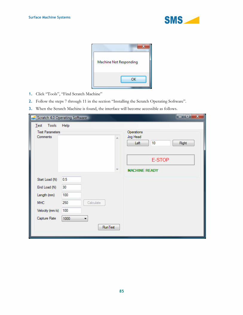
1. Click “Tools”, “Find Scratch Machine”
2. Follow the steps 7 through 11 in the section “Installing the Scratch Operating Software”.
3. When the Scratch Machine is found, the interface will become accessible as follows.


![The Programmer’s Learning Machine: A Teaching System To ... · Scratch, Alice and Greenfoot are very renowned educational projects to teach and learn programming. Scratch [13] enables](https://static.documents.pub/doc/80x56/5f32bd54b57980669f0e7797/the-programmeras-learning-machine-a-teaching-system-to-scratch-alice-and.jpg)


